Embed Size (px)
Citation preview
M
DET3TA, DET3TC, DET3TD and DET4TD Earth Ground Electrode Testers
USER MANUAL
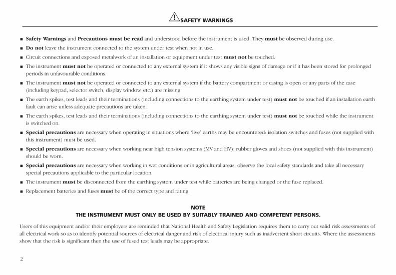
GSAFETY WARNINGS
Safety Warnings and Precautions must be read and understood before the instrument is used. They must be observed during use.
Do not leave the instrument connected to the system under test when not in use.
Circuit connections and exposed metalwork of an installation or equipment under test must not be touched.
The instrument must not be operated or connected to any external system if it shows any visible signs of damage or if it has been stored for prolongedperiods in unfavourable conditions.
The instrument must not be operated or connected to any external system if the battery compartment or casing is open or any parts of the case(including keypad, selector switch, display window, etc.) are missing.
The earth spikes, test leads and their terminations (including connections to the earthing system under test) must not be touched if an installation earthfault can arise unless adequate precautions are taken.
The earth spikes, test leads and their terminations (including connections to the earthing system under test) must not be touched while the instrumentis switched on.
Special precautions are necessary when operating in situations where ‘live’ earths may be encountered: isolation switches and fuses (not supplied withthis instrument) must be used.
Special precautions are necessary when working near high tension systems (MV and HV): rubber gloves and shoes (not supplied with this instrument)should be worn.
Special precautions are necessary when working in wet conditions or in agricultural areas: observe the local safety standards and take all necessaryspecial precautions applicable to the particular location.
The instrument must be disconnected from the earthing system under test while batteries are being changed or the fuse replaced.
Replacement batteries and fuses must be of the correct type and rating.
2
Users of this equipment and/or their employers are reminded that National Health and Safety Legislation requires them to carry out valid risk assessments ofall electrical work so as to identify potential sources of electrical danger and risk of electrical injury such as inadvertent short circuits. Where the assessmentsshow that the risk is significant then the use of fused test leads may be appropriate.
NOTETHE INSTRUMENT MUST ONLY BE USED BY SUITABLY TRAINED AND COMPETENT PERSONS.
3
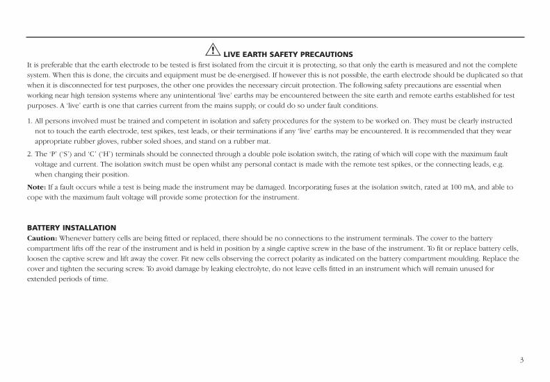
G LIVE EARTH SAFETY PRECAUTIONSIt is preferable that the earth electrode to be tested is first isolated from the circuit it is protecting, so that only the earth is measured and not the completesystem. When this is done, the circuits and equipment must be de-energised. If however this is not possible, the earth electrode should be duplicated so thatwhen it is disconnected for test purposes, the other one provides the necessary circuit protection. The following safety precautions are essential whenworking near high tension systems where any unintentional ‘live’ earths may be encountered between the site earth and remote earths established for testpurposes. A ‘live’ earth is one that carries current from the mains supply, or could do so under fault conditions.
1. All persons involved must be trained and competent in isolation and safety procedures for the system to be worked on. They must be clearly instructednot to touch the earth electrode, test spikes, test leads, or their terminations if any ‘live’ earths may be encountered. It is recommended that they wearappropriate rubber gloves, rubber soled shoes, and stand on a rubber mat.
2. The ‘P’ (‘S’) and ‘C’ (‘H’) terminals should be connected through a double pole isolation switch, the rating of which will cope with the maximum faultvoltage and current. The isolation switch must be open whilst any personal contact is made with the remote test spikes, or the connecting leads, e.g.when changing their position.
Note: If a fault occurs while a test is being made the instrument may be damaged. Incorporating fuses at the isolation switch, rated at 100 mA, and able tocope with the maximum fault voltage will provide some protection for the instrument.
BATTERY INSTALLATIONCaution: Whenever battery cells are being fitted or replaced, there should be no connections to the instrument terminals. The cover to the batterycompartment lifts off the rear of the instrument and is held in position by a single captive screw in the base of the instrument. To fit or replace battery cells,loosen the captive screw and lift away the cover. Fit new cells observing the correct polarity as indicated on the battery compartment moulding. Replace thecover and tighten the securing screw. To avoid damage by leaking electrolyte, do not leave cells fitted in an instrument which will remain unused forextended periods of time.
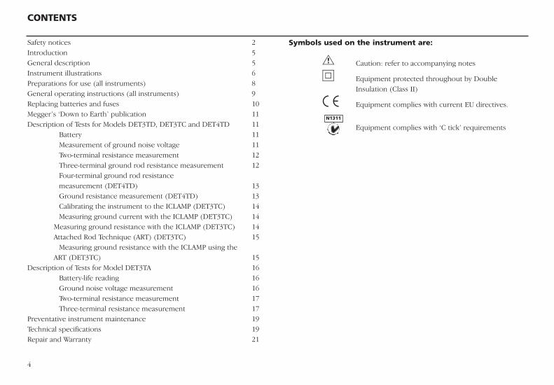
Symbols used on the instrument are:
G Caution: refer to accompanying notes
t Equipment protected throughout by Double Insulation (Class II)
c Equipment complies with current EU directives.
Equipment complies with ‘C tick’ requirements
CONTENTS
4
Safety notices 2Introduction 5General description 5Instrument illustrations 6Preparations for use (all instruments) 8General operating instructions (all instruments) 9Replacing batteries and fuses 10Megger’s ‘Down to Earth’ publication 11Description of Tests for Models DET3TD, DET3TC and DET4TD 11
Battery 11Measurement of ground noise voltage 11Two-terminal resistance measurement 12Three-terminal ground rod resistance measurement 12Four-terminal ground rod resistance measurement (DET4TD) 13Ground resistance measurement (DET4TD) 13Calibrating the instrument to the ICLAMP (DET3TC) 14Measuring ground current with the ICLAMP (DET3TC) 14
Measuring ground resistance with the ICLAMP (DET3TC) 14Attached Rod Technique (ART) (DET3TC) 15
Measuring ground resistance with the ICLAMP using the ART (DET3TC) 15
Description of Tests for Model DET3TA 16Battery-life reading 16Ground noise voltage measurement 16Two-terminal resistance measurement 17Three-terminal resistance measurement 17
Preventative instrument maintenance 19Technical specifications 19Repair and Warranty 21
N1311
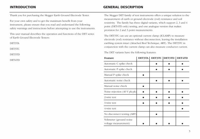
The Megger DET family of test instruments offers a unique solution to themeasurement of earth or ground electrode (rod) resistance and soilresistivity. The family has three digital variants, which support 2, 3 and 4point (DET4TD only) testing, and one analogue version that makesprovision for 2 and 3 point measurements.
The DET3TC can use an optional current clamp (ICLAMP) to measureelectrode (rod) resistance without disconnection, leaving the installationearthing system intact (Attached Rod Technique, ART). The DET3TC inconjunction with the current clamp can also measure conductor current.
The DET variants have the following features:
Feature DET3TA DET3TC DET3TD DET4TD
Automatic C spike check
Automatic P spike check
Manual P spike check
Automatic noise check
Manual noise check
Noise rejection (40 V pk-pk)
2-wire test
3-wire test
4-wire test
No disconnect testing (ART)
Voltmeter (ground noisevoltage measurement)
INTRODUCTION GENERAL DESCRIPTION
5
Thank you for purchasing the Megger Earth Ground Electrode Tester.
For your own safety and to get the maximum benefit from yourinstrument, please ensure that you read and understand the followingsafety warnings and instructions before attempting to use the instruments.
This user manual describes the operation and functions of the DET seriesof Earth Ground Electrode Testers:
DET3TA
DET3TC
DET3TD
DET4TD
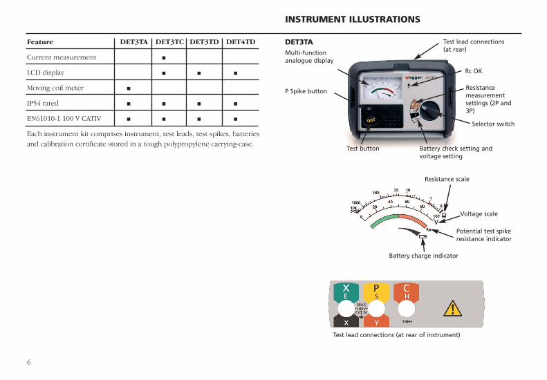
DET3TA
INSTRUMENT ILLUSTRATIONS
6
Feature DET3TA DET3TC DET3TD DET4TD
Current measurement
LCD display
Moving coil meter
IP54 rated
EN61010-1 100 V CATIV
Each instrument kit comprises instrument, test leads, test spikes, batteriesand calibration certificate stored in a tough polypropylene carrying-case.
Test lead connections (at rear)
Rc OK
Selector switch
Resistancemeasurementsettings (2P and3P)
Resistance scale
Voltage scale
Potential test spikeresistance indicator
Battery charge indicator
Test lead connections (at rear of instrument)
Battery check setting andvoltage setting
Multi-function analogue display
Test button
P Spike button
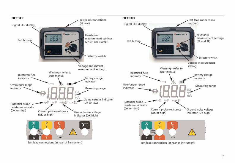
DET3TC DET3TD
7
Test lead connections (at rear)
Resistance measurement settings(2P, 3P and clamp)
Selector switch
Voltage and currentmeasurement settings
Test button
Digital LCD display Digital LCD display
Warning - refer toUser manual
Battery chargeindicator
Measuring rangeMeasuring range
Ruptured fuseindicator
Over/under rangeindicator
Potential proberesistance indicator(OK or high) Current probe resistance
(OK or high)
Clamp current indicator(OK or low)
Ground noise voltageindicator (OK high)
Test lead connections (at rear of instrument) Test lead connections (at rear of instrument)
Warning - refer toUser manual
Over/under rangeindicator
Ruptured fuseindicator
Potential proberesistance indicator(OK or high) Current probe resistance
(OK or high)Ground noise voltageindicator (OK high)
Battery chargeindicator
Test lead connections (at rear)
Resistance measurement settings (2P and 3P)
Selector switch
Voltage measurementsettings
Test button
8
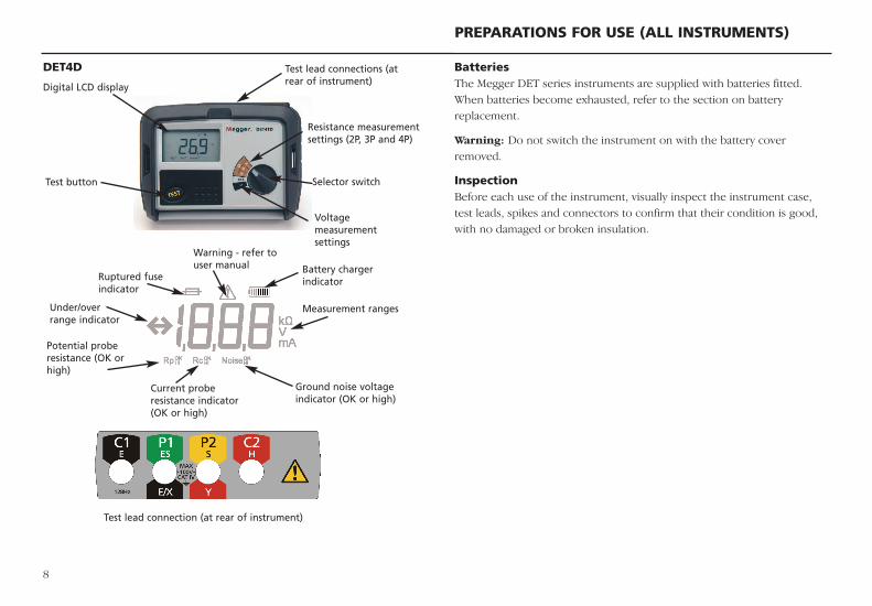
BatteriesThe Megger DET series instruments are supplied with batteries fitted.When batteries become exhausted, refer to the section on batteryreplacement.
Warning: Do not switch the instrument on with the battery coverremoved.
InspectionBefore each use of the instrument, visually inspect the instrument case,test leads, spikes and connectors to confirm that their condition is good,with no damaged or broken insulation.
DET4D
PREPARATIONS FOR USE (ALL INSTRUMENTS)
Test lead connections (atrear of instrument)
Resistance measurementsettings (2P, 3P and 4P)
Selector switch
Voltagemeasurementsettings
Test button
Warning - refer touser manual
Ruptured fuseindicator
Under/overrange indicator
Potential proberesistance (OK orhigh)
Test lead connection (at rear of instrument)
Current proberesistance indicator(OK or high)
Ground noise voltageindicator (OK or high)
Measurement ranges
Battery chargerindicator
Digital LCD display
Instrument output voltage selectionThe maximum output voltage of the instrument is nominally 50 V. Shouldit prove necessary in particular circumstances, it is possible to set theoutput voltage 25 V. The procedure for changing the output voltage is asfollows:
1. Press and hold the TEST button and switch instrument ON to the Vsetting on the selector switch.
2. The LCD display will indicate ‘tst’ (DET3TC, DET3TD and DET4TD).
3. Release TEST button. The maximum output test voltage will bedisplayed, either ‘50 V’ or ‘25 V’.
4. To toggle between the maximum output test voltages, press the TESTbutton.
5. Switch off instrument when the desired maximum test voltage isdisplayed.
Auto power downTo extend battery life the instrument will automatically switch off sixminutes after the last operation.
The instrument can be switched off manually by selecting the ‘OFF’ settingon the selector switch and then switched on as normal.
Display symbols (DET3TC, DET3TD, DET4TD)
G Warning Triangle
f Fuse Blown
Battery Indicator (not DET3TA).
>100V Indicates that the ground noise voltage exceeds the instrument measurement capability.
Rp OK Potential spike (P Spike) resistance is within range for accurate measurement.
9
Rp Hi Potential spike (P Spike) resistance exceeds range for accurate measurement.
Rc OK Current spike (C Spike) resistance is within range for accurate measurement.
Rc Hi Current spike (C Spike) resistance exceeds range for accurate measurement.
Noise OK Ground noise voltage is within range for accurate measurement (<40 Vpk-pk).
Noise Hi Ground noise voltage exceeds range for accurate measurement (>40 Vpk-pk).
Display symbols (DET3TA)Current spike (C Spike) resistance is within range for accurate measurement.
Instrument is performing measurement checks.
GENERAL OPERATING INSTRUCTIONS (ALL INSTRUMENTS)
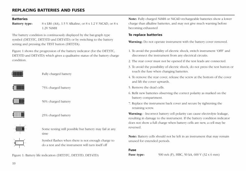
BatteriesBattery type: 8 x LR6 (AA), 1.5 V Alkaline, or 8 x 1.2 V NiCAD, or 8 x
1.2V NiMH
The battery condition is continuously displayed by the bar-graph typesymbol (DET3TC, DET3TD and DET4TD) or by switching to the batterysetting and pressing the TEST button (DET3TA).
Figure 1 shows the progression of the battery indicator (for the DET3TC,DET3TD and DET4TD) which gives a qualitative status of the battery chargecondition.
Fully charged battery
75% charged battery
50% charged battery
25% charged battery
Some testing still possible but battery may fail at any time
Symbol flashes when there is not enough charge to do a test and the instrument will turn itself off
Figure 1: Battery life indication (DET3TC, DET3TD, DET4TD)
REPLACING BATTERIES AND FUSES
Note: Fully charged NiMH or NiCAD rechargeable batteries show a lowercharge than alkaline batteries, and may not give much warning beforebecoming exhausted
To replace batteries
Warning: Do not operate instrument with the battery cover removed.
1. To avoid the possibility of electric shock, switch instrument ‘OFF’ anddisconnect the instrument from any electrical circuits.
2. The rear cover must not be opened if the test leads are connected.
3. To avoid the possibility of electric shock, do not press the test button ortouch the fuse when changing batteries.
4. To remove the rear cover, release the screw at the bottom of the coverand lift the cover upwards.
5. Remove the dead cells.
6. Refit new batteries observing the correct polarity as marked on thebattery compartment.
7. Replace the instrument back cover and secure by tightening theretaining screw.
Warning: - Incorrect battery cell polarity can cause electrolyte leakage,resulting in damage to the instrument. If the battery condition indicatordoes not show a full charge when battery cells are new, a cell may bereversed.
Note: Battery cells should not be left in an instrument that may remainunused for extended periods.
Fuse Fuse type: 500 mA (F), HBC, 50 kA, 600 V (32 x 6 mm)
10
11
The following descriptions of tests are a set of instructions for the solepurpose of the proper use of these instruments by competent persons.Where there is doubt about a particular application, reference should bemade to the advice and guidance contained within the publication ‘Down toEarth’, available from Megger.
DESCRIPTION OF TESTS FOR MODELS DET3TC, DET3TD DET4TDBattery Before proceeding with measurements, ensure that the charge condition ofthe batteries is sufficient to undertake the intended measurements. Thecharge status is given in the bar-graph, as shown in Figure 1, which iscontinually shown on the LCD when the instrument is switched on.
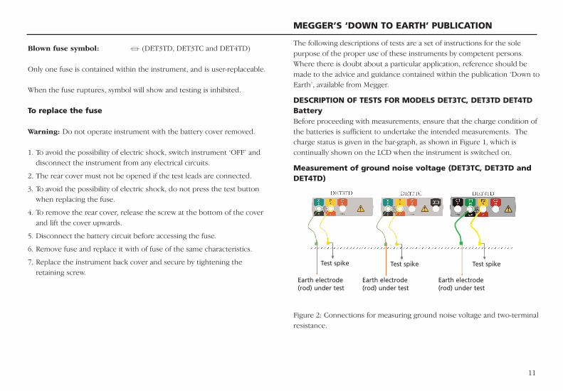
Measurement of ground noise voltage (DET3TC, DET3TD andDET4TD)
Figure 2: Connections for measuring ground noise voltage and two-terminalresistance.
Blown fuse symbol: f (DET3TD, DET3TC and DET4TD)
Only one fuse is contained within the instrument, and is user-replaceable.
When the fuse ruptures, symbol will show and testing is inhibited.
To replace the fuse
Warning: Do not operate instrument with the battery cover removed.
1. To avoid the possibility of electric shock, switch instrument ‘OFF’ anddisconnect the instrument from any electrical circuits.
2. The rear cover must not be opened if the test leads are connected.
3. To avoid the possibility of electric shock, do not press the test buttonwhen replacing the fuse.
4. To remove the rear cover, release the screw at the bottom of the coverand lift the cover upwards.
5. Disconnect the battery circuit before accessing the fuse.
6. Remove fuse and replace it with of fuse of the same characteristics.
7. Replace the instrument back cover and secure by tightening theretaining screw.
MEGGER’S ‘DOWN TO EARTH’ PUBLICATION
Earth electrode(rod) under test
Earth electrode(rod) under test
Earth electrode(rod) under test
Test spike Test spike Test spike
12
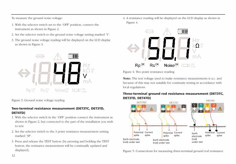
4. A resistance reading will be displayed on the LCD display as shown inFigure 4.
Figure 4: Two point resistance reading
Note: The test voltage used to make resistance measurements is a.c. andbecause of this may not suitable for continuity testing in accordance withlocal regulations.
Three-terminal ground rod resistance measurement (DET3TC,DET3TD, DET4TD)
Figure 5: Connections for measuring three-terminal ground rod resistance
To measure the ground noise voltage:
1. With the selector switch set to the ‘OFF' position, connect theinstrument as shown in Figure 2.
2. Set the selector switch to the ground noise voltage setting marked ‘V’.
3. The ground noise voltage reading will be displayed on the LCD displayas shown in Figure 3.
Figure 3: Ground noise voltage reading
Two-terminal resistance measurement (DET3TC, DET3TD,DET4TD)1. With the selector switch in the ‘OFF’ position connect the instrument as
shown in Figure 2, but connected to the part of the installation you wishto test
2. Set the selector switch to the 3 point resistance measurement settingmarked ‘3P’.
3. Press and release the TEST button [by pressing and holding the TESTbutton, the resistance measurement will be continually updated anddisplayed].
Earth electrode(rod) under test
Earth electrode(rod) under test
Earthelectrode(rod) under test
Currentspike
Currentspike
Currentspike
Potentialspike
Potentialspike
Potentialspike
DET4TD
1. With the selector switch in the ’OFF’ position, connect the instrumentas shown in Figure 5.
2. Set the selector switch to the 3 point resistance measurement settingmarked ‘4P’.
3. Press and release the TEST button [by pressing and holding the TESTbutton, the resistance measurement will be continually updated anddisplayed].
4. The instrument will then check for ground noise, the parameters of thecurrent and voltage circuits and the integrity of the fuse.
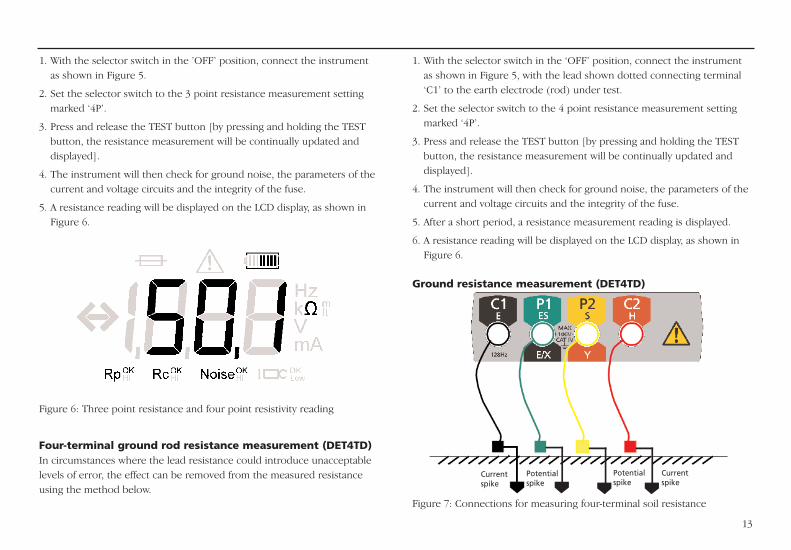
5. A resistance reading will be displayed on the LCD display, as shown inFigure 6.
Figure 6: Three point resistance and four point resistivity reading
Four-terminal ground rod resistance measurement (DET4TD)In circumstances where the lead resistance could introduce unacceptablelevels of error, the effect can be removed from the measured resistanceusing the method below.
1. With the selector switch in the ‘OFF’ position, connect the instrumentas shown in Figure 5, with the lead shown dotted connecting terminal‘C1’ to the earth electrode (rod) under test.
2. Set the selector switch to the 4 point resistance measurement settingmarked ‘4P’.
3. Press and release the TEST button [by pressing and holding the TESTbutton, the resistance measurement will be continually updated anddisplayed].
4. The instrument will then check for ground noise, the parameters of thecurrent and voltage circuits and the integrity of the fuse.
5. After a short period, a resistance measurement reading is displayed.
6. A resistance reading will be displayed on the LCD display, as shown inFigure 6.
Ground resistance measurement (DET4TD)
Figure 7: Connections for measuring four-terminal soil resistance
Currentspike
Currentspike
Potentialspike
Potentialspike
13
8. The instrument is now calibrated to the particular ICLAMP.
9. Switch the instrument to the OFF position.
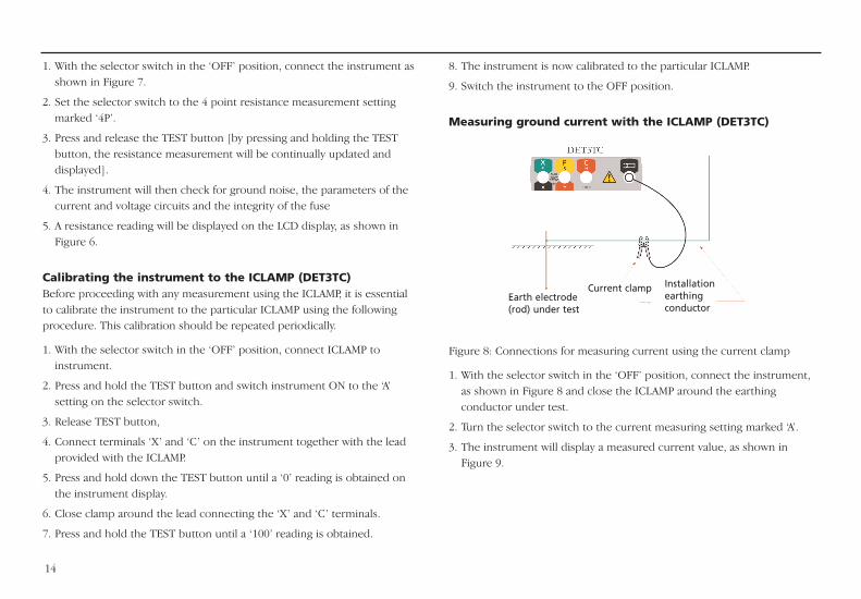
Measuring ground current with the ICLAMP (DET3TC)
Figure 8: Connections for measuring current using the current clamp
1. With the selector switch in the ‘OFF’ position, connect the instrument,as shown in Figure 8 and close the ICLAMP around the earthingconductor under test.
2. Turn the selector switch to the current measuring setting marked ‘A’.
3. The instrument will display a measured current value, as shown inFigure 9.
14
Earth electrode(rod) under test
Current clamp Installationearthing conductor
1. With the selector switch in the ‘OFF’ position, connect the instrument asshown in Figure 7.
2. Set the selector switch to the 4 point resistance measurement settingmarked ‘4P’.
3. Press and release the TEST button [by pressing and holding the TESTbutton, the resistance measurement will be continually updated anddisplayed].
4. The instrument will then check for ground noise, the parameters of thecurrent and voltage circuits and the integrity of the fuse
5. A resistance reading will be displayed on the LCD display, as shown inFigure 6.
Calibrating the instrument to the ICLAMP (DET3TC) Before proceeding with any measurement using the ICLAMP, it is essentialto calibrate the instrument to the particular ICLAMP using the followingprocedure. This calibration should be repeated periodically.
1. With the selector switch in the ‘OFF’ position, connect ICLAMP toinstrument.
2. Press and hold the TEST button and switch instrument ON to the ‘A’setting on the selector switch.
3. Release TEST button,
4. Connect terminals ‘X’ and ‘C’ on the instrument together with the leadprovided with the ICLAMP.
5. Press and hold down the TEST button until a ‘0’ reading is obtained onthe instrument display.
6. Close clamp around the lead connecting the ‘X’ and ‘C’ terminals.
7. Press and hold the TEST button until a ‘100’ reading is obtained.
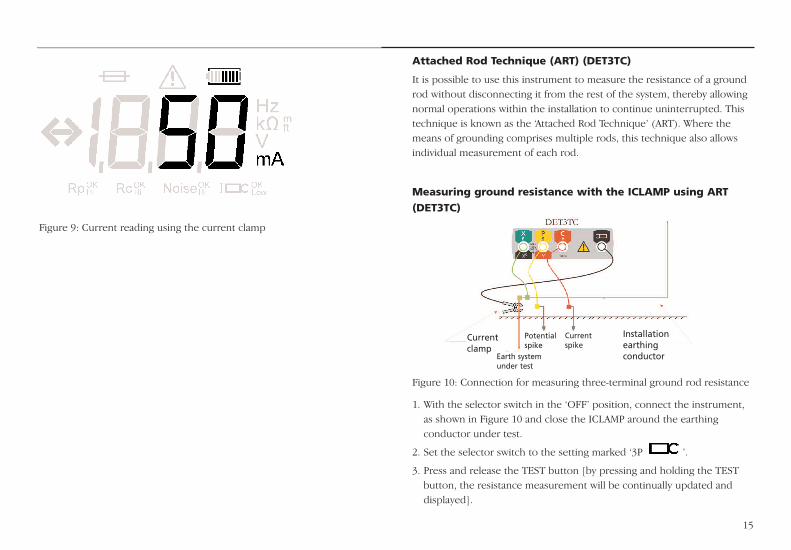
Figure 9: Current reading using the current clamp
15
Attached Rod Technique (ART) (DET3TC)
It is possible to use this instrument to measure the resistance of a groundrod without disconnecting it from the rest of the system, thereby allowingnormal operations within the installation to continue uninterrupted. Thistechnique is known as the ‘Attached Rod Technique’ (ART). Where themeans of grounding comprises multiple rods, this technique also allowsindividual measurement of each rod.
Measuring ground resistance with the ICLAMP using ART
(DET3TC)
Figure 10: Connection for measuring three-terminal ground rod resistance
1. With the selector switch in the ‘OFF’ position, connect the instrument,as shown in Figure 10 and close the ICLAMP around the earthingconductor under test.
2. Set the selector switch to the setting marked ‘3P ’.
3. Press and release the TEST button [by pressing and holding the TESTbutton, the resistance measurement will be continually updated anddisplayed].
Installationearthing conductor
Currentclamp
Potentialspike
Earth systemunder test
Current spike
16
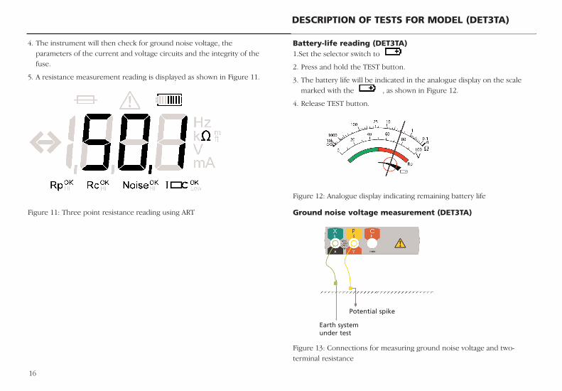
Battery-life reading (DET3TA)1.Set the selector switch to
2. Press and hold the TEST button.
3. The battery life will be indicated in the analogue display on the scalemarked with the , as shown in Figure 12.
4. Release TEST button.
Figure 12: Analogue display indicating remaining battery life
Ground noise voltage measurement (DET3TA)
Figure 13: Connections for measuring ground noise voltage and two-terminal resistance
4. The instrument will then check for ground noise voltage, theparameters of the current and voltage circuits and the integrity of thefuse.
5. A resistance measurement reading is displayed as shown in Figure 11.
Figure 11: Three point resistance reading using ART
DESCRIPTION OF TESTS FOR MODEL (DET3TA)
Potential spike
Earth system under test
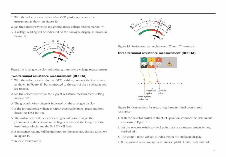
Figure 15: Resistance reading between ‘X’ and ‘Y’ terminals
Three-terminal resistance measurement (DET3TA)
Figure 16: Connections for measuring three-terminal ground rodresistance
1. With the selector switch in the ‘OFF’ position, connect the instrumentas shown in Figure 16.
2. Set the selector switch to the 3 point resistance measurement settingmarked ‘3P’.
3. The ground noise voltage is indicated on the analogue display.
4. If the ground noise voltage is within acceptable limits, push and hold
17
1. With the selector switch set to the ‘OFF’ position, connect theinstrument as shown in Figure 13.
2. Set the selector switch to the ground noise voltage setting marked ‘V’.
3. A voltage reading will be indicated on the analogue display, as shown inFigure 14.
Figure 14: Analogue display indicating ground noise voltage measurement
Two-terminal resistance measurement (DET3TA)1. With the selector switch in the ‘OFF’ position, connect the instrument
as shown in Figure 13, but connected to the part of the installation youare testing.
2. Set the selector switch to the 2 point resistance measurement settingmarked ‘2P’.
3. The ground noise voltage is indicated on the analogue display
4. If the ground noise voltage is within acceptable limits, press and holddown the TEST button.
5. The instrument will then check for ground noise voltage, theparameters of the current and voltage circuits and the integrity of thefuse during which time the Rc LED will flash.
6. A resistance reading will be indicated on the analogue display, as shownin Figure 15.
7. Release TEST button.
Potentialspike
Currentspike
Earth systemunder test
10. Continuous illumination of the Rc LED indicates that the resistance of the current circuit is within limits.
11. A resistance reading will be indicated on the analogue display, as shownin Figure 15.
12. On completion of measurement, release the TEST button.
18
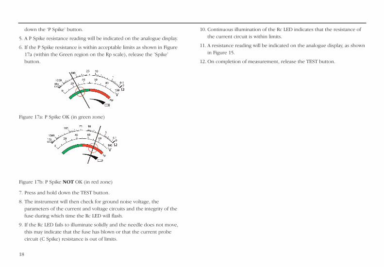
down the ‘P Spike’ button.
5. A P Spike resistance reading will be indicated on the analogue display.
6. If the P Spike resistance is within acceptable limits as shown in Figure17a (within the Green region on the Rp scale), release the ’Spike’button.
Figure 17a: P Spike OK (in green zone)
Figure 17b: P Spike NOT OK (in red zone)
7. Press and hold down the TEST button.
8. The instrument will then check for ground noise voltage, theparameters of the current and voltage circuits and the integrity of thefuse during which time the Rc LED will flash.
9. If the Rc LED fails to illuminate solidly and the needle does not move,this may indicate that the fuse has blown or that the current probecircuit (C Spike) resistance is out of limits.
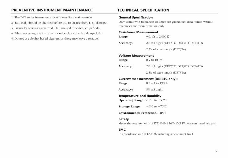
1. The DET series instruments require very little maintenance.
2. Test leads should be checked before use to ensure there is no damage.
3. Ensure batteries are removed if left unused for extended periods.
4. When necessary, the instrument can be cleaned with a damp cloth.
5. Do not use alcohol-based cleaners, as these may leave a residue.
19
PREVENTIVE INSTRUMENT MAINTENANCE
General SpecificationOnly values with tolerances or limits are guaranteed data. Values withouttolerances are for information only.
Resistance MeasurementRange: 0.01 Ω to 2,000 Ω
Accuracy: 2% ±3 digits (DET3TC, DET3TD, DET4TD)
2.5% of scale length (DET3TA)
Voltage MeasurementRange: 0 V to 100 V
Accuracy: 2% ±3 digits (DET3TC, DET3TD, DET4TD)
2.5% of scale length (DET3TA)
Current measurement (DET3TC only):Range: 0.5 mA to 19.9 A
Accuracy: 5% ±3 digits
Temperature and HumidityOperating Range: -15ºC to +55ºC
Storage Range: -40ºC to +70ºC
Environmental Protection: IP54
SafetyMeets the requirements of EN61010-1 100V CAT IV between terminal pairs.
EMCIn accordance with IEC61326 including amendment No.1
TECHNICAL SPECIFICATION
20
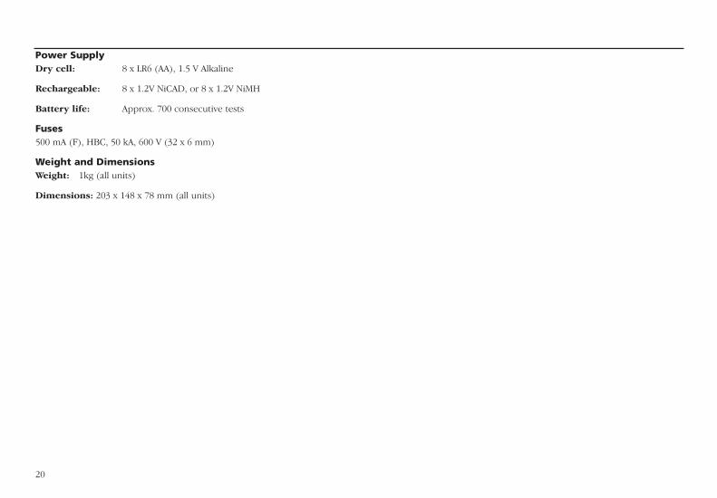
Power SupplyDry cell: 8 x LR6 (AA), 1.5 V Alkaline
Rechargeable: 8 x 1.2V NiCAD, or 8 x 1.2V NiMH
Battery life: Approx. 700 consecutive tests
Fuses500 mA (F), HBC, 50 kA, 600 V (32 x 6 mm)
Weight and DimensionsWeight: 1kg (all units)
Dimensions: 203 x 148 x 78 mm (all units)
21
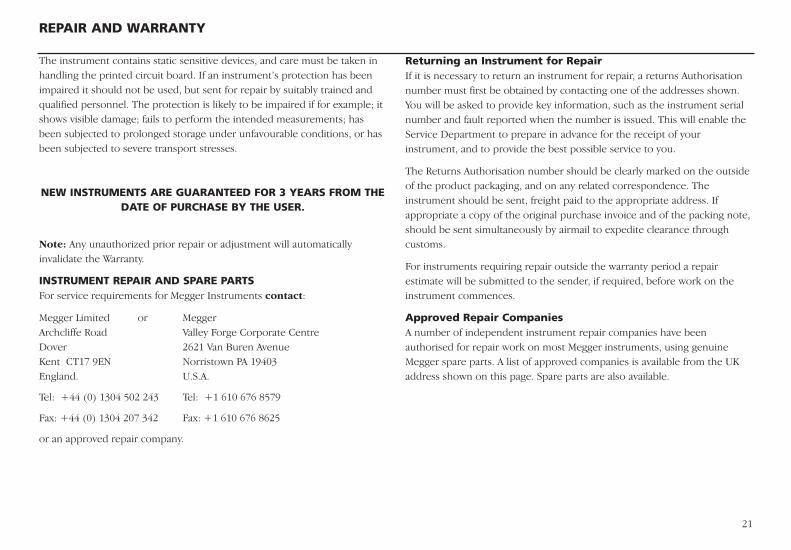
The instrument contains static sensitive devices, and care must be taken inhandling the printed circuit board. If an instrument’s protection has beenimpaired it should not be used, but sent for repair by suitably trained andqualified personnel. The protection is likely to be impaired if for example; itshows visible damage; fails to perform the intended measurements; hasbeen subjected to prolonged storage under unfavourable conditions, or hasbeen subjected to severe transport stresses.
NEW INSTRUMENTS ARE GUARANTEED FOR 3 YEARS FROM THEDATE OF PURCHASE BY THE USER.
Note: Any unauthorized prior repair or adjustment will automaticallyinvalidate the Warranty.
INSTRUMENT REPAIR AND SPARE PARTSFor service requirements for Megger Instruments contact:
Megger Limited or Megger Archcliffe Road Valley Forge Corporate CentreDover 2621 Van Buren AvenueKent CT17 9EN Norristown PA 19403England. U.S.A.
Tel: +44 (0) 1304 502 243 Tel: +1 610 676 8579
Fax: +44 (0) 1304 207 342 Fax: +1 610 676 8625
or an approved repair company.
Returning an Instrument for RepairIf it is necessary to return an instrument for repair, a returns Authorisationnumber must first be obtained by contacting one of the addresses shown.You will be asked to provide key information, such as the instrument serialnumber and fault reported when the number is issued. This will enable theService Department to prepare in advance for the receipt of yourinstrument, and to provide the best possible service to you.
The Returns Authorisation number should be clearly marked on the outsideof the product packaging, and on any related correspondence. Theinstrument should be sent, freight paid to the appropriate address. Ifappropriate a copy of the original purchase invoice and of the packing note,should be sent simultaneously by airmail to expedite clearance throughcustoms.
For instruments requiring repair outside the warranty period a repairestimate will be submitted to the sender, if required, before work on theinstrument commences.
Approved Repair CompaniesA number of independent instrument repair companies have beenauthorised for repair work on most Megger instruments, using genuineMegger spare parts. A list of approved companies is available from the UKaddress shown on this page. Spare parts are also available.
REPAIR AND WARRANTY
M
Megger LimitedArchcliffe Road, DoverKent CT17 9EN England T +44 (0)1 304 502101 F +44 (0)1 304 207342E [email protected]
Megger 4271 Bronze Way, Dallas, Texas 75237-1019 USAT +1 800 723 2861 (USA ONLY)T +1 214 333 3201 F +1 214 331 7399E [email protected]
Megger Z.A. Du Buisson de la Couldre23 rue Eugène Henaff78190 TRAPPES FranceT +33 (0)1 30.16.08.90F +33 (0)1 34.61.23.77E [email protected]
Megger Pty LimitedUnit 26 9 Hudson AvenueCastle HillSydney NSW 2125 AustraliaT +61 (0)2 9659 2005F +61 (0)2 9659 2201E [email protected]
Megger Limited110 Milner Avenue Unit 1Scarborough Ontario M1S 3R2CanadaT +1 416 298 9688 (Canada only)T +1 416 298 6770F +1 416 298 0848E [email protected]
Megger products are distributed in 146 countries worldwide.
This instrument is manufactured in the United Kingdom.The company reserves the right to change the specification or design without prior notice.
Megger is a registered trademark
Part No. DET3TA_DET3TC_DET3TD_DET4TD V02 1205www.megger.com


![Untitled-3 [] using.pdf · Grounding Conductor Protective Conductor 6. (Ground Rod Grounding Electrode Earth Electrode) 16 (5/8 2.40 7. a18Gi0hñõu (Grounding Electrode](https://img.pdfslide.us/doc/110x75/5f88252e30e96c229e75bb1a/untitled-3-usingpdf-grounding-conductor-protective-conductor-6-ground-rod.jpg)


![Performance of HVDC Ground Electrode in Various Soil ... Ground Electrode Design.pdf · [1,2]. Presently, a number of major HVDC projects are taking place in China. The increased](https://img.pdfslide.us/doc/110x75/5ea61723a0035a42982b4ad7/performance-of-hvdc-ground-electrode-in-various-soil-ground-electrode-designpdf.jpg)