Embed Size (px)
Citation preview
DESLIMING OF FINE COAL – WHAT IS THE CORRECT CYCLONE?
E. Bekker
Multotec

ABSTRACT
Defining the correct cyclone design or standard for fine coal beneficiation processes seems to
differ between various companies and operations. This paper will highlight some of the pitfalls of
selecting the correct desliming cyclone parameters and explain some of the deviations witnessed
in the performance the desliming cyclone in a desliming cyclone and spiral circuit.
The selection criteria of the desliming cyclone which is based on particle size distribution data
only, will be compared against scenarios where additional information like fractional ash contents
and washability data is available. The financial impact will be looked at and possible options to
improve current operations.
0
20
40
60
80
100
1 10 100 1000 10000
% P
assi
ng
Size (µm)
Cyclone Overflow PSD
350 mm
500mm
610 mm
900mm
1050mm
350mm (2)
INTRODUCTION
In 2016 Deloitte (Deloitte, 2016) published a document titled “Innovation in Mining – Africa 2016” in which the two main innovation drivers are listed as reducing the cost to operate and improved asset productivity. In the same document a section on the Coal-tech Research Association is included and one of the key areas for innovation listed was the beneficiation of fine and ultra-fine coal.
Over the last couple of years there has been a renewed interest in fine coal beneficiation and how to improve the efficiency of separation of this fine material and how to maximise the recovery of fine material from an operation.
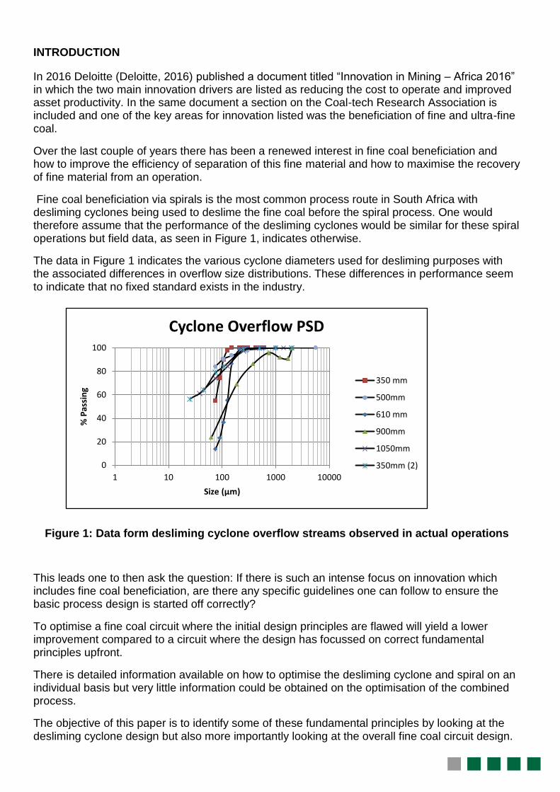
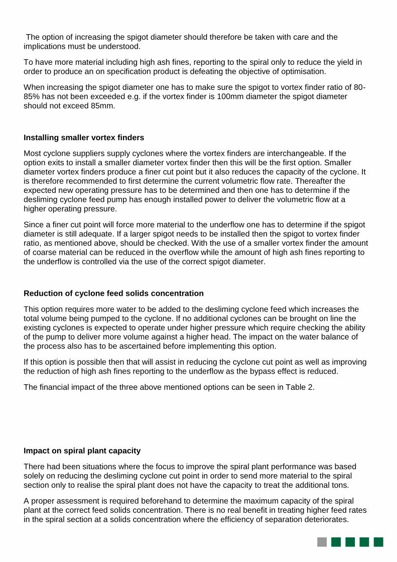
Fine coal beneficiation via spirals is the most common process route in South Africa with desliming cyclones being used to deslime the fine coal before the spiral process. One would therefore assume that the performance of the desliming cyclones would be similar for these spiral operations but field data, as seen in Figure 1, indicates otherwise.
The data in Figure 1 indicates the various cyclone diameters used for desliming purposes with the associated differences in overflow size distributions. These differences in performance seem to indicate that no fixed standard exists in the industry.
Figure 1: Data form desliming cyclone overflow streams observed in actual operations
This leads one to then ask the question: If there is such an intense focus on innovation which includes fine coal beneficiation, are there any specific guidelines one can follow to ensure the basic process design is started off correctly?
To optimise a fine coal circuit where the initial design principles are flawed will yield a lower improvement compared to a circuit where the design has focussed on correct fundamental principles upfront.
There is detailed information available on how to optimise the desliming cyclone and spiral on an individual basis but very little information could be obtained on the optimisation of the combined process.
The objective of this paper is to identify some of these fundamental principles by looking at the desliming cyclone design but also more importantly looking at the overall fine coal circuit design.
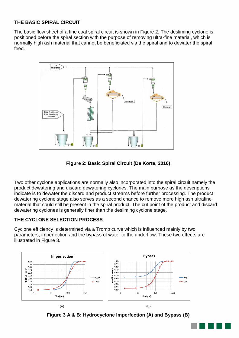
THE BASIC SPIRAL CIRCUIT
The basic flow sheet of a fine coal spiral circuit is shown in Figure 2. The desliming cyclone is positioned before the spiral section with the purpose of removing ultra-fine material, which is normally high ash material that cannot be beneficiated via the spiral and to dewater the spiral feed.
Figure 2: Basic Spiral Circuit (De Korte, 2016)
Two other cyclone applications are normally also incorporated into the spiral circuit namely the product dewatering and discard dewatering cyclones. The main purpose as the descriptions indicate is to dewater the discard and product streams before further processing. The product dewatering cyclone stage also serves as a second chance to remove more high ash ultrafine material that could still be present in the spiral product. The cut point of the product and discard dewatering cyclones is generally finer than the desliming cyclone stage.
THE CYCLONE SELECTION PROCESS
Cyclone efficiency is determined via a Tromp curve which is influenced mainly by two parameters, imperfection and the bypass of water to the underflow. These two effects are illustrated in Figure 3.
(A) (B)
Figure 3 A & B: Hydrocyclone Imperfection (A) and Bypass (B)
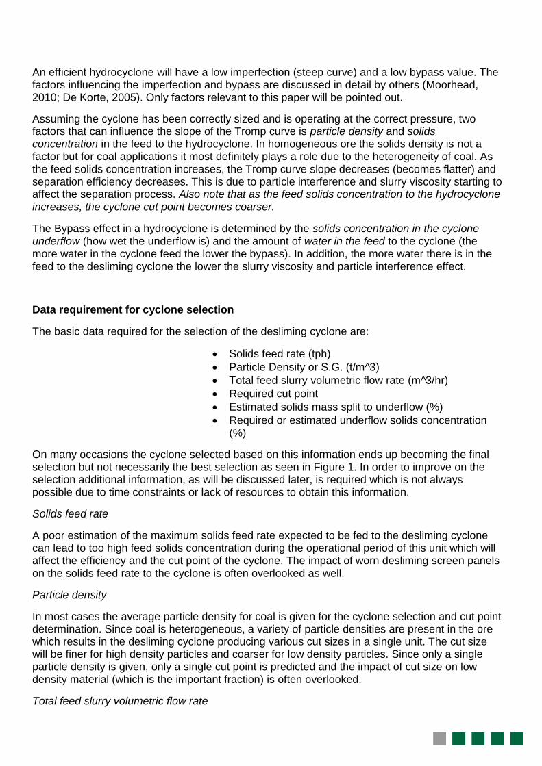
An efficient hydrocyclone will have a low imperfection (steep curve) and a low bypass value. The factors influencing the imperfection and bypass are discussed in detail by others (Moorhead, 2010; De Korte, 2005). Only factors relevant to this paper will be pointed out.
Assuming the cyclone has been correctly sized and is operating at the correct pressure, two factors that can influence the slope of the Tromp curve is particle density and solids concentration in the feed to the hydrocyclone. In homogeneous ore the solids density is not a factor but for coal applications it most definitely plays a role due to the heterogeneity of coal. As the feed solids concentration increases, the Tromp curve slope decreases (becomes flatter) and separation efficiency decreases. This is due to particle interference and slurry viscosity starting to affect the separation process. Also note that as the feed solids concentration to the hydrocyclone increases, the cyclone cut point becomes coarser.
The Bypass effect in a hydrocyclone is determined by the solids concentration in the cyclone underflow (how wet the underflow is) and the amount of water in the feed to the cyclone (the more water in the cyclone feed the lower the bypass). In addition, the more water there is in the feed to the desliming cyclone the lower the slurry viscosity and particle interference effect.
Data requirement for cyclone selection
The basic data required for the selection of the desliming cyclone are:
Solids feed rate (tph)
Particle Density or S.G. (t/m^3)
Total feed slurry volumetric flow rate (m^3/hr)
Required cut point
Estimated solids mass split to underflow (%)
Required or estimated underflow solids concentration (%)
On many occasions the cyclone selected based on this information ends up becoming the final selection but not necessarily the best selection as seen in Figure 1. In order to improve on the selection additional information, as will be discussed later, is required which is not always possible due to time constraints or lack of resources to obtain this information.
Solids feed rate
A poor estimation of the maximum solids feed rate expected to be fed to the desliming cyclone can lead to too high feed solids concentration during the operational period of this unit which will affect the efficiency and the cut point of the cyclone. The impact of worn desliming screen panels on the solids feed rate to the cyclone is often overlooked as well.
Particle density
In most cases the average particle density for coal is given for the cyclone selection and cut point determination. Since coal is heterogeneous, a variety of particle densities are present in the ore which results in the desliming cyclone producing various cut sizes in a single unit. The cut size will be finer for high density particles and coarser for low density particles. Since only a single particle density is given, only a single cut point is predicted and the impact of cut size on low density material (which is the important fraction) is often overlooked.
Total feed slurry volumetric flow rate
This value is determined by the maximum solids feed rate and the feed solids concentration to the desliming cyclone. The under estimation of the maximum solids feed rate can therefore result in an incorrect total volumetric flow rate calculation and under estimation of the cyclone capacity. As a result of limited capacity available, extra feed tonnages are accommodated by increasing the cyclone feed solids concentration which then impact on the cyclone bypass value and cyclone cut point.
Required cut point
In literature the cyclone cut point refers to that particle size that has a 50% change of either reporting to underflow or to overflow. In many instances it has become clear that the definition of cyclone cut point has been misunderstood by either the supplier or client which then leads to the desliming cyclone not performing adequately.
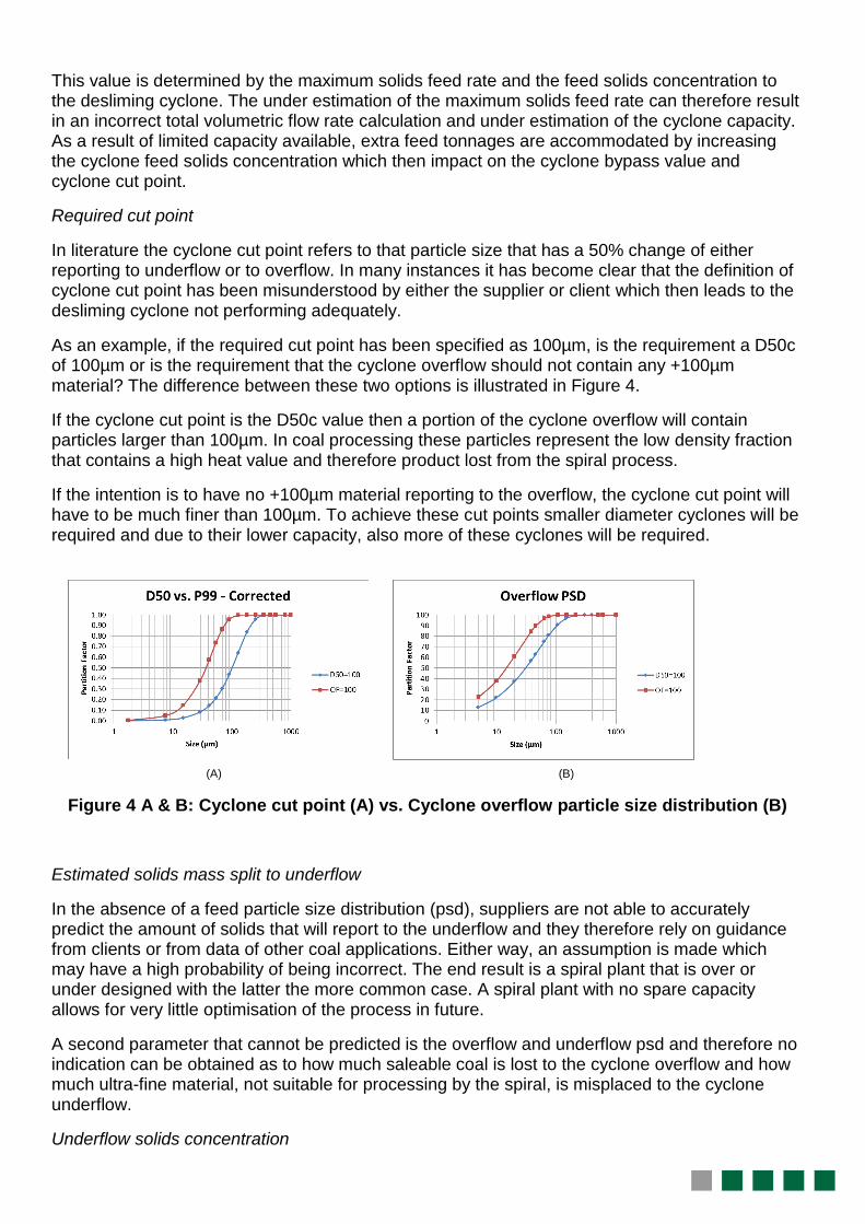
As an example, if the required cut point has been specified as 100µm, is the requirement a D50c of 100µm or is the requirement that the cyclone overflow should not contain any +100µm material? The difference between these two options is illustrated in Figure 4.
If the cyclone cut point is the D50c value then a portion of the cyclone overflow will contain particles larger than 100µm. In coal processing these particles represent the low density fraction that contains a high heat value and therefore product lost from the spiral process.
If the intention is to have no +100µm material reporting to the overflow, the cyclone cut point will have to be much finer than 100µm. To achieve these cut points smaller diameter cyclones will be required and due to their lower capacity, also more of these cyclones will be required.
(A) (B)
Figure 4 A & B: Cyclone cut point (A) vs. Cyclone overflow particle size distribution (B)
Estimated solids mass split to underflow
In the absence of a feed particle size distribution (psd), suppliers are not able to accurately predict the amount of solids that will report to the underflow and they therefore rely on guidance from clients or from data of other coal applications. Either way, an assumption is made which may have a high probability of being incorrect. The end result is a spiral plant that is over or under designed with the latter the more common case. A spiral plant with no spare capacity allows for very little optimisation of the process in future.
A second parameter that cannot be predicted is the overflow and underflow psd and therefore no indication can be obtained as to how much saleable coal is lost to the cyclone overflow and how much ultra-fine material, not suitable for processing by the spiral, is misplaced to the cyclone underflow.
Underflow solids concentration
The specification of the underflow solids concentration determines the spigot diameter on the hydrocyclone together with the mass split of solids to the underflow. In most cases an incorrect spigot diameter can be rectified by replacing the spigot with the correct diameter. Situations can however exist where major modifications are required if the assumptions on underflow density and mass split were wrong. During this period before modifications are made, the operation the desliming cyclone will be poor.
COAL SPIRAL PROCESS REQUIREMENT
Before looking at the desliming cyclone design, a look at the spiral process design is required.
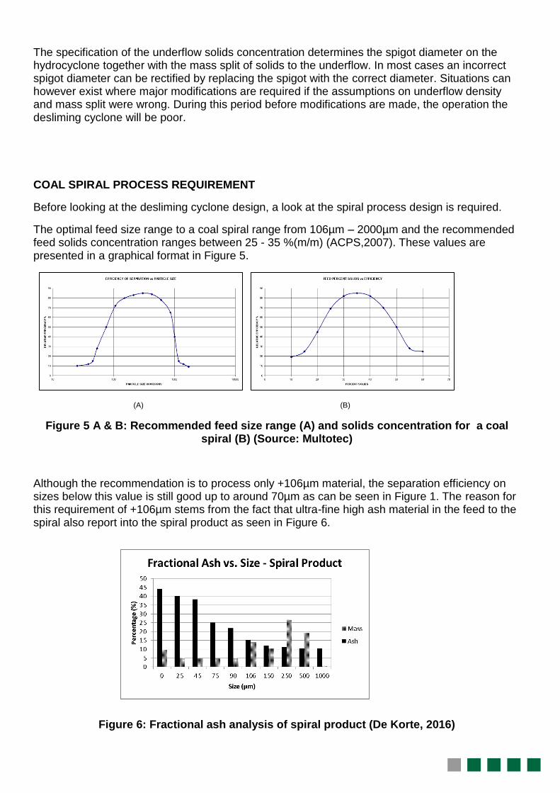
The optimal feed size range to a coal spiral range from 106µm – 2000µm and the recommended feed solids concentration ranges between 25 - 35 %(m/m) (ACPS,2007). These values are presented in a graphical format in Figure 5.
(A) (B)
Figure 5 A & B: Recommended feed size range (A) and solids concentration for a coal spiral (B) (Source: Multotec)
Although the recommendation is to process only +106µm material, the separation efficiency on sizes below this value is still good up to around 70µm as can be seen in Figure 1. The reason for this requirement of +106µm stems from the fact that ultra-fine high ash material in the feed to the spiral also report into the spiral product as seen in Figure 6.
Figure 6: Fractional ash analysis of spiral product (De Korte, 2016)
Below 106µm the fractional ash content increases which affects the final spiral product quality negatively and therefore the general guideline is to reduce the amount of -106µm material in the feed to the spiral. This is achieved currently by specifying the desliming cyclone cut point to be in the range of 106µm – 250µm. Of interest however is the -75µm fraction and especially the -25µm fraction as this represents the highest ash content and relatively high amount of mass. If the cyclone cut point is specified as ranging between 106µm - 250µm, how does this material still end up in the feed to the spiral?
A portion of the answer is found in the second graph in Figure 5 which indicates the optimum spiral feed solids concentration as 35% although the recommendation ranges from 25% to 35% (m/m). The other portion of the answer relates to the impact of the cyclone feed solids concentration on the bypass effect discussed earlier in this paper.
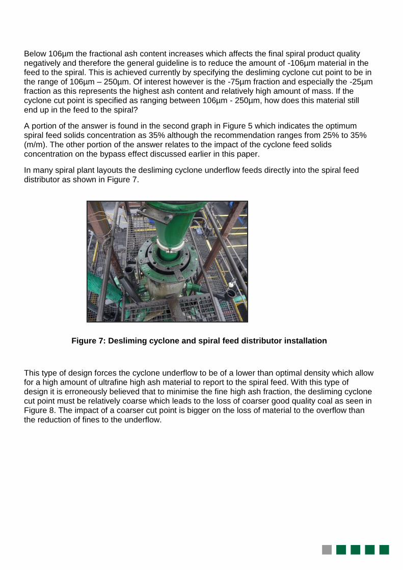
In many spiral plant layouts the desliming cyclone underflow feeds directly into the spiral feed distributor as shown in Figure 7.
Figure 7: Desliming cyclone and spiral feed distributor installation
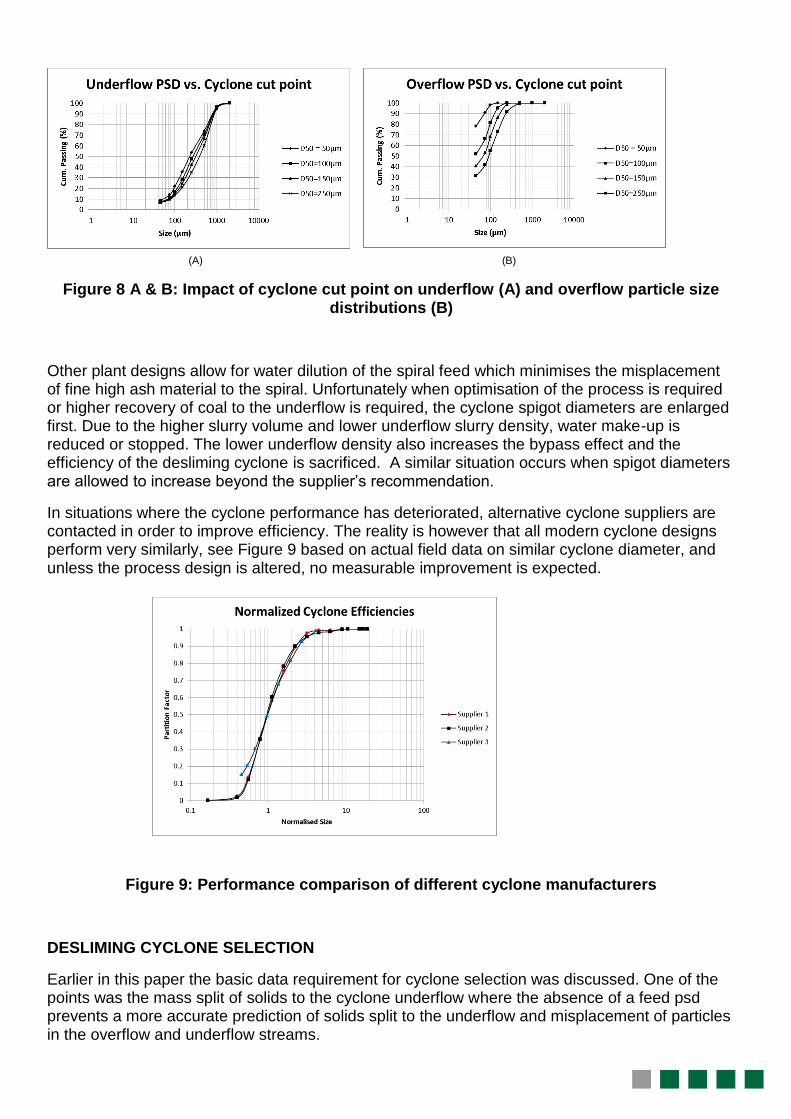
This type of design forces the cyclone underflow to be of a lower than optimal density which allow for a high amount of ultrafine high ash material to report to the spiral feed. With this type of design it is erroneously believed that to minimise the fine high ash fraction, the desliming cyclone cut point must be relatively coarse which leads to the loss of coarser good quality coal as seen in Figure 8. The impact of a coarser cut point is bigger on the loss of material to the overflow than the reduction of fines to the underflow.
(A) (B)
Figure 8 A & B: Impact of cyclone cut point on underflow (A) and overflow particle size distributions (B)
Other plant designs allow for water dilution of the spiral feed which minimises the misplacement of fine high ash material to the spiral. Unfortunately when optimisation of the process is required or higher recovery of coal to the underflow is required, the cyclone spigot diameters are enlarged first. Due to the higher slurry volume and lower underflow slurry density, water make-up is reduced or stopped. The lower underflow density also increases the bypass effect and the efficiency of the desliming cyclone is sacrificed. A similar situation occurs when spigot diameters are allowed to increase beyond the supplier’s recommendation.
In situations where the cyclone performance has deteriorated, alternative cyclone suppliers are contacted in order to improve efficiency. The reality is however that all modern cyclone designs perform very similarly, see Figure 9 based on actual field data on similar cyclone diameter, and unless the process design is altered, no measurable improvement is expected.
Figure 9: Performance comparison of different cyclone manufacturers
DESLIMING CYCLONE SELECTION
Earlier in this paper the basic data requirement for cyclone selection was discussed. One of the points was the mass split of solids to the cyclone underflow where the absence of a feed psd prevents a more accurate prediction of solids split to the underflow and misplacement of particles in the overflow and underflow streams.
Cyclone data which includes a feed psd
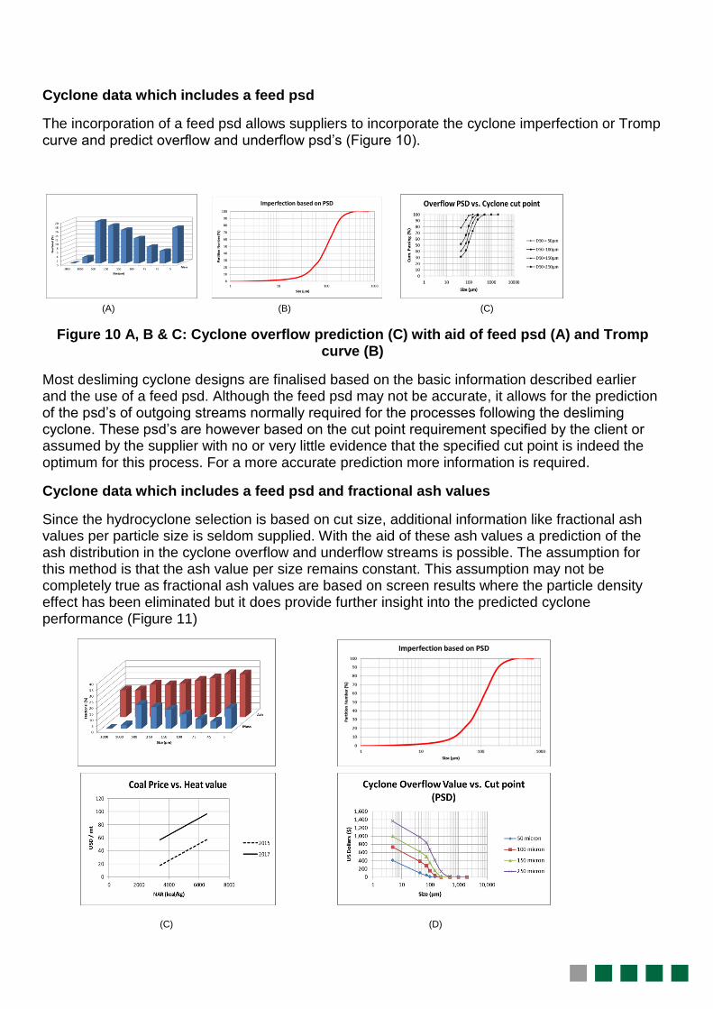
The incorporation of a feed psd allows suppliers to incorporate the cyclone imperfection or Tromp curve and predict overflow and underflow psd’s (Figure 10).
(A) (B) (C)
Figure 10 A, B & C: Cyclone overflow prediction (C) with aid of feed psd (A) and Tromp curve (B)
Most desliming cyclone designs are finalised based on the basic information described earlier and the use of a feed psd. Although the feed psd may not be accurate, it allows for the prediction of the psd’s of outgoing streams normally required for the processes following the desliming cyclone. These psd’s are however based on the cut point requirement specified by the client or assumed by the supplier with no or very little evidence that the specified cut point is indeed the optimum for this process. For a more accurate prediction more information is required.
Cyclone data which includes a feed psd and fractional ash values
Since the hydrocyclone selection is based on cut size, additional information like fractional ash values per particle size is seldom supplied. With the aid of these ash values a prediction of the ash distribution in the cyclone overflow and underflow streams is possible. The assumption for this method is that the ash value per size remains constant. This assumption may not be completely true as fractional ash values are based on screen results where the particle density effect has been eliminated but it does provide further insight into the predicted cyclone performance (Figure 11)
(C) (D)
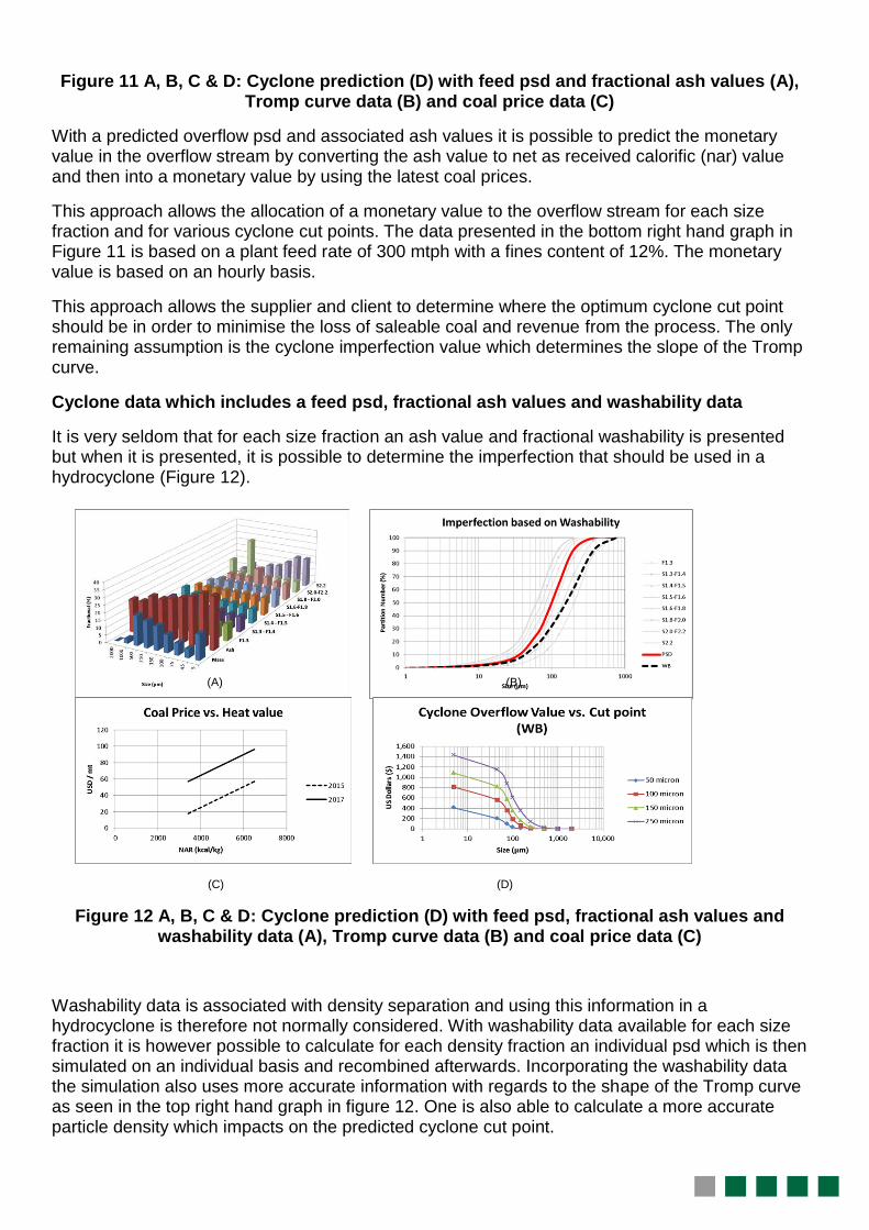
Figure 11 A, B, C & D: Cyclone prediction (D) with feed psd and fractional ash values (A), Tromp curve data (B) and coal price data (C)
With a predicted overflow psd and associated ash values it is possible to predict the monetary value in the overflow stream by converting the ash value to net as received calorific (nar) value and then into a monetary value by using the latest coal prices.
This approach allows the allocation of a monetary value to the overflow stream for each size fraction and for various cyclone cut points. The data presented in the bottom right hand graph in Figure 11 is based on a plant feed rate of 300 mtph with a fines content of 12%. The monetary value is based on an hourly basis.
This approach allows the supplier and client to determine where the optimum cyclone cut point should be in order to minimise the loss of saleable coal and revenue from the process. The only remaining assumption is the cyclone imperfection value which determines the slope of the Tromp curve.
Cyclone data which includes a feed psd, fractional ash values and washability data
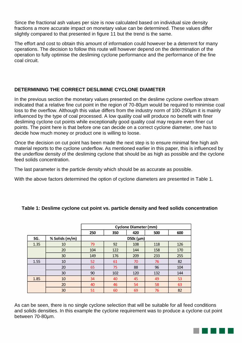
It is very seldom that for each size fraction an ash value and fractional washability is presented but when it is presented, it is possible to determine the imperfection that should be used in a hydrocyclone (Figure 12).
(A) (B)
(C) (D)
Figure 12 A, B, C & D: Cyclone prediction (D) with feed psd, fractional ash values and washability data (A), Tromp curve data (B) and coal price data (C)
Washability data is associated with density separation and using this information in a hydrocyclone is therefore not normally considered. With washability data available for each size fraction it is however possible to calculate for each density fraction an individual psd which is then simulated on an individual basis and recombined afterwards. Incorporating the washability data the simulation also uses more accurate information with regards to the shape of the Tromp curve as seen in the top right hand graph in figure 12. One is also able to calculate a more accurate particle density which impacts on the predicted cyclone cut point.
250 350 420 500 600
SG. % Solids (m/m)
1.35 10 79 92 108 118 126
20 104 122 144 158 170
30 149 176 209 233 255
1.55 10 52 61 70 76 82
20 65 75 88 96 104
30 90 102 120 132 144
1.85 10 34 40 45 49 53
20 40 46 54 58 63
30 51 60 69 76 82
Cyclone Diameter (mm)
D50c (µm)
Since the fractional ash values per size is now calculated based on individual size density fractions a more accurate impact on monetary value can be determined. These values differ slightly compared to that presented in figure 11 but the trend is the same.
The effort and cost to obtain this amount of information could however be a deterrent for many operations. The decision to follow this route will however depend on the determination of the operation to fully optimise the desliming cyclone performance and the performance of the fine coal circuit.
DETERMINING THE CORRECT DESLIMINE CYCLONE DIAMETER
In the previous section the monetary values presented on the deslime cyclone overflow stream indicated that a relative fine cut point in the region of 70-80µm would be required to minimise coal loss to the overflow. Although this value differs from the industry norm of 100-250µm it is mainly influenced by the type of coal processed. A low quality coal will produce no benefit with finer desliming cyclone cut points while exceptionally good quality coal may require even finer cut points. The point here is that before one can decide on a correct cyclone diameter, one has to decide how much money or product one is willing to loose.
Once the decision on cut point has been made the next step is to ensure minimal fine high ash material reports to the cyclone underflow. As mentioned earlier in this paper, this is influenced by the underflow density of the desliming cyclone that should be as high as possible and the cyclone feed solids concentration.
The last parameter is the particle density which should be as accurate as possible.
With the above factors determined the option of cyclone diameters are presented in Table 1.
Table 1: Deslime cyclone cut point vs. particle density and feed solids concentration
As can be seen, there is no single cyclone selection that will be suitable for all feed conditions and solids densities. In this example the cyclone requirement was to produce a cyclone cut point between 70-80µm.
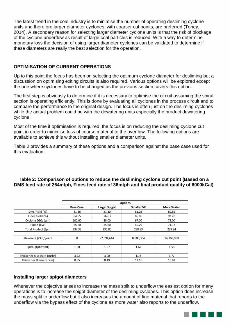
Base Case Larger Spigot Smaller VF More Water
DMS Yield (%) 81.36 81.30 81.03 80.86
Fines Yield (%) 84.55 76.63 85.06 93.20
Cyclone D50c (µm) 100.00 88.00 67.00 73.00
Pump (kW) 35.80 35.80 46.29 71.17
Total Product (tph) 237.33 236.80 238.83 239.84
Revenue (ZAR/year) 0 -2,994,644 8,580,304 14,368,060
Spiral (tph/start) 1.50 1.67 1.67 1.58
Thickener Rise Rate (m/hr) 3.72 3.00 1.73 1.77
Thickener Diameter (m) 8.35 8.49 12.16 15.81
Options
The latest trend in the coal industry is to minimise the number of operating desliming cyclone units and therefore larger diameter cyclones, with coarser cut points, are preferred (Toney, 2014). A secondary reason for selecting larger diameter cyclone units is that the risk of blockage of the cyclone underflow as result of large coal particles is reduced. With a way to determine monetary loss the decision of using larger diameter cyclones can be validated to determine if these diameters are really the best selection for the operation.
OPTIMISATION OF CURRENT OPERATIONS
Up to this point the focus has been on selecting the optimum cyclone diameter for desliming but a discussion on optimising exiting circuits is also required. Various options will be explored except the one where cyclones have to be changed as the previous section covers this option.
The first step is obviously to determine if it is necessary to optimise the circuit assuming the spiral section is operating efficiently. This is done by evaluating all cyclones in the process circuit and to compare the performance to the original design. The focus is often just on the desliming cyclones while the actual problem could be with the dewatering units especially the product dewatering cyclone.
Most of the time if optimisation is required, the focus is on reducing the desliming cyclone cut point in order to minimise loss of coarse material to the overflow. The following options are available to achieve this without installing smaller diameter units.
Table 2 provides a summary of these options and a comparison against the base case used for this evaluation.
Table 2: Comparison of options to reduce the desliming cyclone cut point (Based on a DMS feed rate of 264mtph, Fines feed rate of 36mtph and final product quality of 6000kCal)
Installing larger spigot diameters
Whenever the objective arises to increase the mass split to underflow the easiest option for many operations is to increase the spigot diameter of the desliming cyclones. This option does increase the mass split to underflow but it also increases the amount of fine material that reports to the underflow via the bypass effect of the cyclone as more water also reports to the underflow.
The option of increasing the spigot diameter should therefore be taken with care and the implications must be understood.
To have more material including high ash fines, reporting to the spiral only to reduce the yield in order to produce an on specification product is defeating the objective of optimisation.
When increasing the spigot diameter one has to make sure the spigot to vortex finder ratio of 80-85% has not been exceeded e.g. if the vortex finder is 100mm diameter the spigot diameter should not exceed 85mm.
Installing smaller vortex finders
Most cyclone suppliers supply cyclones where the vortex finders are interchangeable. If the option exits to install a smaller diameter vortex finder then this will be the first option. Smaller diameter vortex finders produce a finer cut point but it also reduces the capacity of the cyclone. It is therefore recommended to first determine the current volumetric flow rate. Thereafter the expected new operating pressure has to be determined and then one has to determine if the desliming cyclone feed pump has enough installed power to deliver the volumetric flow at a higher operating pressure.
Since a finer cut point will force more material to the underflow one has to determine if the spigot diameter is still adequate. If a larger spigot needs to be installed then the spigot to vortex finder ratio, as mentioned above, should be checked. With the use of a smaller vortex finder the amount of coarse material can be reduced in the overflow while the amount of high ash fines reporting to the underflow is controlled via the use of the correct spigot diameter.
Reduction of cyclone feed solids concentration
This option requires more water to be added to the desliming cyclone feed which increases the total volume being pumped to the cyclone. If no additional cyclones can be brought on line the existing cyclones is expected to operate under higher pressure which require checking the ability of the pump to deliver more volume against a higher head. The impact on the water balance of the process also has to be ascertained before implementing this option.
If this option is possible then that will assist in reducing the cyclone cut point as well as improving the reduction of high ash fines reporting to the underflow as the bypass effect is reduced.
The financial impact of the three above mentioned options can be seen in Table 2.
Impact on spiral plant capacity
There had been situations where the focus to improve the spiral plant performance was based solely on reducing the desliming cyclone cut point in order to send more material to the spiral section only to realise the spiral plant does not have the capacity to treat the additional tons.
A proper assessment is required beforehand to determine the maximum capacity of the spiral plant at the correct feed solids concentration. There is no real benefit in treating higher feed rates in the spiral section at a solids concentration where the efficiency of separation deteriorates.
This is sometimes the case where small modular plants have been designed on a limited budget and in order to reduce the footprint of the spiral plant, maximum tonnages have been used as the design basis. In cases like this virtually no room exists to accommodate additional feed tonnages and any optimisation effort will effectively become fruitless unless more spirals are installed.
The impact of the three evaluated options on the spiral feed rate can be seen in Table 2. In this example the original spiral design was based on 1.5tph/start. Should the spiral plant have been designed at 3tph/start all the options would have resulted in an overload of the spiral circuit unless more spiral were installed.
Impact on dewatering cyclones
The dewatering cyclones is not often considered in the optimisation process and in most cases it may not present a problem as these units generally operate at low feed solids concentrations. Additional tonnages can therefore be accommodated.
It is however still recommended that the impact of higher feed rates to the spiral section be investigated. Areas to investigate are the spigot loading to ensure roping is not starting to take place with resulting product misplacement to overflow on the product dewatering cyclone. If the product dewatering cyclone overflow exits the process then any solids present in the overflow is lost from the beneficiation process. If the product dewatering cyclone overflow is returned back into the process a possibility exists that a build-up of solids may occur in the process over time. Roping of the discard dewatering cyclone can lead to a higher solids loading in the thickener which in extreme cases can exceed the thickener solids extraction rate.
Impact on thickener and filter press
The thickener is very seldom evaluated in a fines spiral plant optimisation process as it is generally designed with a safety factor to cater for varying solids loading. To handle increases in volumetric loading, alternative flocculent types are employed for increased settling rates. The basic thickener design requires the rise rate of the liquid to be slower than the settling rate of the solids in order to provide a clear overflow. Should the solids settling rate decrease, the clarified water will be contaminated with solids which can be detrimental to the beneficiation process.
Due to environmental legislation and to reduce water loss, it is becoming more common to dewater the thickener underflow via filter presses before discarding the dry solids with the outgoing discard streams. Should the filter press be unable to handle the solids loading, the feed rate to the coal processing plant can be compromised.
Optimisation of the fines circuit normally focuses on recovering more saleable coal from the discard streams. There are however some cases where the optimisation process focuses on removing solids from the effluent streams going to the thickener as the filter press capacity becomes the limiting factor in the coal processing route.
As mentioned the impact of decreasing the desliming cyclone cut point seldom considers the impact it may have on the thickener and filter press if it is present.
Looking back at the options available to the operator in decreasing the cut point of the desliming cyclones, all the options will result in a decrease in the cyclone overflow particle size distribution reporting to the thickener which means an impact in the settling velocity of the solids in the thickener can be expected. The option of additional water being added to the desliming cyclone feed exacerbates the situation in that additional volume of water is also added to the thickener which increases the rise rate inside the thickener.
The impact of the three options to reduce the desliming cyclone cut point on the thickener diameter can be seen in Table 2. For simplicity purposes the rise rate equals the settling rate of the solids which were then used to calculate the thickener diameter. The use of different types of flocculants, to increase the solids settling rate, has not been considered. The impact on filter press capacity has also not been considered as most exiting plants operate without filter presses.
Reducing the impact on the thickener and filter press
In a recent case the requirement on the desliming cyclone circuit called for more coarse material to be presented to the thickener to aid in settling rates and filtration rates of the filter press. This meant an increase in the loss of saleable product from the process.
Where the thickener underflow and filter press product is discarded an alternative option exits to introduce coarse material into this stream and that is to change the discard dewatering cyclone into a classification cyclone. In dewatering applications the cyclone design is such that the cyclone cut point is finer compared to the desliming cyclone cut point. This means that the discard dewatering cyclone overflow will contain predominately fine material in the overflow stream.
By changing the cyclone diameter or cyclone configuration the cut point can be increased substantially which then allows for the introduction of coarser material into the thickener feed stream to aid in settling rates and if a filter press is present, also the filtrations rates.
CONCLUSION
The correct cyclone selection is based on a proper understanding of factors influencing the performance of the desliming cyclone and the data required to perform an accurate selection. By attaching a monetary value to the cyclone performance a more accurate indication is obtained of which unit will be optimal instead of using the standard industry guidelines developed over the years.
The correct cyclone selection will depend on the objectives of the organisation and the feed parameters to the cyclone. There is therefore not a one size fits all solution.
In many operations a focus to improve the fine coal process only focuses on changing the performance of the desliming cyclones. It is recommended to evaluate the complete process in order to develop a proper understanding of how this change will impact on the complete process. Spiral capacity, dewatering cyclone performance, thickener performance and filter press (if installed) performances are some of the areas that should not be overlooked.
REFERENCES
1. Australian Coal Processing Society (ACPS), 2007, The Principles of Coal Preparation 4th Edition, G.J. Sanders, Australian Coal Processing Society, p.304
2. De Korte G.J., 2016, Processing fine and ultra-fine coal, Inside Mining, ISSN 1999-8872, Vol.9, No.10, October 2016, p. 32-34
3. De Korte G.J., 2005, Task 4.11.1(a) – Desliming of Fine Coal, http://www.google.co.za/url?sa=t&rct=j&q=&esrc=s&source=web&cd=18&cad=rja&uact=8&ved=0ahUKEwi3ptrL7b_SAhXlI8AKHT4IDsY4ChAWCF4wBw&url=http%3A%2F%2Fwww.coaltech.co.za%2Fchamber%2520databases%255Ccoaltech%255CCom_DocMan.nsf%2F0%2FF8F8DF2F19AE057F4225740300201A66%2F%24File%2FTask%25204.11.1(a)%2520-%2520De-Sliming%2520of%2520Fine%2520Coal.pdf&usg=AFQjCNGbqkNy6ZDXPDfpb49gi4VYQmwH0Q, [Accessed March 2017]
4. Deloitte, 2016, Innovation in Mining – Africa 2016, https://www.google.co.za/url?sa=t&rct=j&q=&esrc=s&source=web&cd=2&cad=rja&uact=8&ved=0ahUKEwiMutjs0b_SAhWqK8AKHZVvC3IQFggxMAE&url=https%3A%2F%2Fwww2.deloitte.com%2Fcontent%2Fdam%2FDeloitte%2Fza%2FDocuments%2Fenergy-resources%2FInnovation_in_mining_2016_v2.pdf&usg=AFQjCNGMV9h5xgwia-8JxxmvxIRTQvtvCQ&bvm=bv.148747831,d.d2s [Accessed March 2017]
5. Moorhead R., 2010, Classifying Cyclones, CPSA -The Coal Prep Primer, Kip Alderman, The Coal Preparation Society of America, Chapter 13
Toney T., Bozzato P., 2014, The Cost of Saving Money in Coal Preparation, Coal Age,
http://www.google.co.za/url?sa=t&rct=j&q=&esrc=s&source=web&cd=1&cad=rja&uact=8&ved
=0ahUKEwjw59Kk77_SAhUrJsAKHcg4DzYQFgggMAA&url=http%3A%2F%2Fwww.coalage.
com%2Fdepartments%2Foperating-ideas%2F3689-the-cost-of-saving-money-in-coal-
preparation.html&usg=AFQjCNEess3S3T1RglizrvWvowo8C2M5wg,


![Cyclone Handbook, Section I. Cyclone FPGA Family Data Sheet1]EP1C12F256C8.pdf · Section I. Cyclone FPGA Family Data Sheet ... Cyclone Device Handbook, ... Vertical migration means](https://img.pdfslide.us/doc/110x75/5b3a24897f8b9a600a8f2cfc/cyclone-handbook-section-i-cyclone-fpga-family-data-sheet-1ep1c12f256c8pdf.jpg)