Embed Size (px)
Citation preview

DESKPOWER 5000 Series User’s Manual
Fujitsu endeavours to ensure that the information in this document is correct, but accepts no liabilityfor any error or omission in the same. Any procedures described in this document for operatingFujitsu products should be read and understood by the operator before such products are used.To ensure that Fujitsu products function without risk to safety and health, such procedures shouldbe strictly observed by the operator. The development of Fujitsu products and services iscontinuous and published information may not be up to date. Any particular issue of a productmay contain facilities not described herein. It is important to check the current position with Fujitsu.Specifications and statements as to performance in this document are Fujitsu estimates intendedfor general guidance. They may require adjustment in particular circumstances and shouldtherefore not be taken as formal offers or commitments.
DESKPOWER is a trademark of Fujitsu Limited. The following are registered trademarks ofMiscrosoft Corporation: MS, MS-DOS, Windows® NT, Windows® for Workgroups, Windows® 95,Windows® 98, Windows® 2000. Intel 810E, Celeron,Pentium II and III are the registered trademark of Intel Corporation. Phoenix and the Phoenix logo are registered trademarks of PhoenixTechnologies, Ltd. Intel® Pentium™ and MMX™ technology are trademarks of Intel Corporation.ATI Graphic Chip: RAGE PRO TURBO and RAGE XL are the registered trademarks of ATITechnologies, Inc. Award is the registered trademark of Award Software International Inc.
All Rights Reserved. Copyright© Fujitsu Limited, 2000
The use of screens is permitted by Microsoft Corporation in the United States.
All other products are trademarks or registered trademarks of their respective companies.
© Copyright 2000 Fujitsu Limited. All rights reserved. No part of this publication may be copied,
reproduced, or translated without the prior written consent of Fujitsu Limited. No part of this
publication may be stored or transmitted in any electronic form without the written consent of Fujitsu
Limited.
Fujitsu PC (Asia) Pte Ltd200 Pandan Loop#05-03 Pantech 21The Computer CentreSingapore 128388
Tel : 65-776 0688Fax : 65-776 0788

IMPORTANT SAFETY INSTRUCTIONS1. Read these instructions carefully. Save these instructions for future reference.
2. Follow all warnings and instructions marked on the product.
3. Unplug this product from the wall outlet before cleaning. Do not use liquid cleaners or aerosol cleaners.
Use a damp cloth for cleaning.
4. Do not use this product near water.
5. Do not place this product on an unstable cart, stand, or table. The product may fall, causing serious
damage to the product.
6. Slots and openings in the cabinet and the back or bottom are provided for ventilation; to ensure reliable
operation of the product and to protect it from overheating, these openings must not be blocked or covered.
The openings should never be blocked by placing the product on a bed, sofa, rug, or other similar surface.
This product should never be placed near or over a radiator or heat register, or in a built-in installation
unless proper ventilation is provided.
7. This product should be operated from the type of power indicated on the marking label. If you are not
sure of the type of power available, consult your dealer or local power company.
8. This product is equipped with a 3-wire grounding-type plug, a plug having a third (grounding) pin. This
will only plug into a grounding-type power outlet. This is a safety feature. If you are unable to insert the
plug into the outlet, contact your electrician to replace your obsolete outlet. Do not defeat the purpose
of the grounding-type plug.
9. Do not allow anything to rest on the power cord. Do not locate this product where persons will walk on
the cord.
10. If an extension cord is used with this product, make sure that the total ampere rating of the equipment
plugged into the extension cord does not exceed the extension cord ampere rating. Also, make sure
that the total rating of all products plugged into the wall outlet does not exceed 15 amperes.
11. Never push objects of any kind into this product through cabinet slots as they may touch dangerous
voltage points that could result in a fire or electric shock. Never spill liquid of any kind on the product.
12. Do not attempt to service this product yourself, as opening or removing covers may expose you to
dangerous voltage points or other risks. Refer all servicing to qualified service personnel.
13. Unplug this product from the wall outlet and refer servicing to qualified service personnel under the
following conditions:
a. When the power cord or plug is damaged or frayed.
b. If liquid has been spilled into the product.
c. If the product has been exposed to rain or water.
d. If the product does not operate normally when the operating instructions are followed. Adjust
only those controls that are covered by the operating instructions since improper adjustment
of other controls may result in damage and will often require extensive work by a qualified
technician to restore the product to normal condition.
e. If the product has been dropped or the cabinet has been damaged.
f. If the product exhibits a distinct change in performance, indicating a need for service.
14. CAUTION. When replacing the battery, be sure to install it with the polarities in the correct position.There is a danger of explosion if the battery is replaced with an incorrect type or is mistreated.Do not recharge, disassemble or dispose of in fire. Replace only with the same or equivalenttype recommeded by the manufacturer. Dispose of the used battery according to themanufacturer’s instructions.
15. Use only the proper type of power supply cord set (provided in your accessories box) for this unit. It
should be a detachable type: UL listed/CSA certified, BS1363,ASTA,SS145 certified, rated 10A 250V
minimum, VDE approved or its equivalent. Maximum length is 15 feet (4.6 meters).

■ GreetingsWe thank you for purchasing the Fujitsu DESKPOWER 5000 personal computer.This manual explains how to use the hardware of the DESKPOWER 5000.Please read this manual carefully to ensure correct use of the DESKPOWER 5000.
This unit may malfunction if the power source is interrupted suddenly, for example, due to
lightning. Fujitsu recommends the use of an AC non-interruptible power supply unit.
(Based on guidelines for the prevention of sudden voltage interruptions by Japan Electronic
Industry Development Association (JEIDA).
This unit is class B information technology equipment based on the Voluntary Control Council
for Interference (VCCI) standard by Information Technology Equipment and may create
interference if used near radio or television receivers.
Use the unit in accordance with information provided in the manual.
This unit conforms to the Personal Computer Industry Standard (PC-11-1988) of the Japan
Electronic Industry Development Association (JEIDA).
This unit conforms to the harmonic guideline.
Because this product includes cargo based on the “Foreign Exchange and Foreign Trade
Control Act,” the export of this product may require permission in accordance with said act.
Fujitsu, who is a participant of the International Energy Star Program, determines
that this product conforms to the International Energy Star Program Standard.
The International Energy Star Program is an international program for
promoting energy conservation of office equipment such as computers and
strives to develop and promote products capable of efficient energy use. This program is open
to all manufacturers, and the products to be developed include computers, displays, printers,
facsimiles, and copy machines. The same standard and markings ( ) are used among
participating countries.
The energy-saving function of this product, however, may not be applicable because of
limitations with the operating system (such as Windows NT).

■ Conventions used in this manual
● Warning iconsVarious icons and icon/word combinations are used in this manual to encourage users to use theequipment so as to minimize personal risk and prevent property damage. The icons are explainedas follows. The user should be familiar with the icons before responding to the correspondinginstructions.
Indicates a hazardous situation that could result in fatal or serious
wound if the correct procedure is not applied.
Indicates a hazardous situation that could result in personal injury and/or
property damage if the correct procedure is not applied.
The following icons are also used with the above icon/word combinations to prevent personalinjury and/or property damage.
The icon that indicates the corresponding instruction is a warning.
The illustration displayed inside or beside the icon shows what the
warning actually means.
The icon that indicates the corresponding instruction is a banned
action.The illustration displayed inside or beside the icon shows what is
actually banned.
The icon ● that indicates the corresponding instruction is a command to
proceed. The illustration displayed inside or beside the icon shows what
to proceed.
● Representing keys and use thereofIn the text of the manual, keyboard keys are represented using only necessary characters asshown below.
Example: [Ctrl] key, [Enter] key, and [→] key
When more than one key is to be pressed simultaneously, the keys are represented using "+"between keys as shown below:
Example: [Ctrl] + [F3] and [Shift] + [↑]
● Representing buttonsButtons displayed on the screen are enclosed in square brackets, [and], as shown below:
Example: [OK]
● Command entriesIn the text of the manual, a command is represented as shown below:
A blank (shown with [↑]) between characters indicates that the [Space] key (long bar on the frontof the keyboard) is to be pressed once. Command names are represented in lowercase but maybe entered using uppercase letters.
diskcopy a: a:↑ ↑
WARNING
CAUTION

● Conventions used in the text of the manual
The symbols used in the text of the manual have meanings as explained below:
Point indicates information necessary to run hardware or software.
Help indicates information explaining how to terminate an incorrect operationor troubleshoot.
● Screen display examples
Screen displays provided in this manual are examples and may be different from those (includingfile names) actually appearing on the display screen.
● Illustrations
Illustrations in this manual are an example using (mainly) the DESKPOWER 5000 (CD-ROM drive-equipped model) and may be different from those actually appearing on your PC screen dependingon the model type and options installed.
● Custom-made options
Descriptions in this manual are based on the standard specifications.Note that when custom-made options are installed, memory capacity, hard disk capacity, andother specifications differ from the standard.
● Referencing products
In this manual, products are described using abbreviations as listed below:
Windows 98 refers to Microsoft® Windows® 98 operating system.
Windows NT refers to Microsoft® Windows NT® Workstation operating system Version 4.0.
Windows 2000 refers to Microsoft® Windows® 2000 operating system.
MS-DOS refers to Microsoft(R) MS-DOS(R) operating system Version 6.2/V.
ICU refers to ISA Configuration Utility.
The terms "your PC," "the PC," "your PC main unit," and "the PC main unit" refer to theDESKPOWER 5000
??? Help
¤¤¤¤¤ Point

■ Warning and caution labelsThe PC bears warning and caution labels as shown below.
The warning and caution labels must not be removed or damaged.
● Rear of the PC main unit
WARNING
● Before mounting or dismounting an optional unit in/from your PC, switchoff the PC and all connected units and unplug all power cords fromrespective outlets to prevent electric shock.
Electric shock
● Inside the PC main unit
Electric shock
WARNING To prevent electric shock, switch off the PC and connected peripherals and unplug power cords from respective outlets before disassembling the unit and installing a built-in option.
Electric shock
WARNINGTo prevent electric shock and/or fire, do not remove the cover of this unit, which includes a high voltage section.

Chapter 1 Installation and Connection
This chapter outlines precautions that should be noted wheninstalling the PC and explains how to connect various cables.
Consult this chapter before assembling the PC.
Chapter 2 Basic Operations
This chapter explains basic operations required to use the PC, suchas how to switch the power on and off and how to proceed with storagemedia.
Consult this chapter.
Chapter 3 Installing Internal Options
This chapter explains how to install internal options such as hard diskand expansion cards.Consult this chapter as required.
Chapter 4 Troubleshooting
This chapter explains how to proceed if your PC does not operatecorrectly or if an error message appears.Consult this chapter as required.
Appendix
This appendix provides the name of each component of your PC,information relevant to PC maintenance, the specification of the PCmain unit, and a list of precautions.Consult this appendix.
Manual configuration

Content
Chapter 1 Installation and Connection ............................................ 1
1 Installation ............................................................................. 2Installation location .................................................................................... 2Example of installing the PC ...................................................................... 2Preventing electromagnetic interference with a TV or radio ....................... 3
2 Connection ............................................................................ 4Attaching CRT display, keyboard, mouse, and LAN cables ....................... 5Connecting the power cord ........................................................................ 6Upon completion of all connections ........................................................... 6
Chapter 2 Basic Operations .............................................................. 7
1 Switching on.......................................................................... 8
2 Switching off ....................................................................... 10Turning off the power via Windows 98 ..................................................... 10Turning off the power via Windows NT .................................................... 11
3 Reset .................................................................................... 12Resetting the PC via Windows 98 ............................................................ 12Resetting the PC via Windows NT ........................................................... 12Resetting the PC via Windows 2000 ........................................................ 13Handling precautions ............................................................................... 14Mounting and dismounting a floppy disk .................................................. 14
4 Floppy Disk .......................................................................... 14Handling precautions ............................................................................... 16
5 CD-ROM ............................................................................... 16Mounting and dismounting a CD-ROM disk ............................................ 17
6 Hard Disk ............................................................................. 18What is a hard disk? ................................................................................ 18Handling precautions ............................................................................... 18
Chapter 3 Installing Internal Options ............................................. 19
1 Introduction ......................................................................... 20Handling precautions ............................................................................... 20Installing positions of internal options ...................................................... 21Removing the upper cover ....................................................................... 22Removing the front panel ......................................................................... 22
2 Installing Memory Modules ................................................ 22Memory .................................................................................................... 24Installing an additional memory ............................................................... 24Removing the memory ............................................................................. 25
3 Installing Expansion Cards ................................................ 26Expansion cards for PCI bus (Plug & Play compatible cards) ................. 27Expansion card installation procedure for a PC using Windows 98 ......... 28Expansion card installation procedure for a PC using Windows NT ........ 29Starting and terminating the ICU (For a PC using Windows NT) ............. 30Installing an expansion card .................................................................... 31
4 Installing Expansion Bay Options ..................................... 33Replacing a internal hard disk equipped as standard .............................. 35Installing internal options to 3.5-inch expansion bays .............................. 37Installing internal options to 5-inch expansion bays ................................. 41
Chapter 4 Troubleshooting .............................................................. 45
1 Error Messages ................................................................... 46Error messages displayed by the PC ....................................................... 46Correcting errors ...................................................................................... 49
2 Troubleshooting .................................................................. 50Troubleshooting information on the computer main unit and peripheralunits ......................................................................................................... 50Troubleshooting information on Windows 98 ........................................... 51If an error recurs ...................................................................................... 52
Appendix .......................................................................................... 53
1 Name and Function of Each Component .......................... 54Front of the PC main unit ......................................................................... 54Rear of the PC main unit ......................................................................... 57Inside the PC main unit ............................................................................ 58Motherboard/riser board .......................................................................... 59
2 Standard Specifications ..................................................... 60PC main unit specifications ...................................................................... 60
3 Cleaning Method ................................................................. 66Cleaning the PC main unit ....................................................................... 66Cleaning the keyboard ............................................................................. 66Cleaning a CD-ROM ................................................................................ 66Cleaning the mouse ................................................................................. 66
4 Supplement ......................................................................... 68Peripheral devices and cables ................................................................. 68Note on using the display ......................................................................... 68Note on using an analog liquid crystal display ......................................... 68Digital display output ................................................................................ 68Replacing the display ............................................................................... 68Display and power save mode ................................................................. 69About USB (Windows 98/2000) ............................................................... 69Wake up On LAN ..................................................................................... 70Power Saving Function ............................................................................ 70LAN Cable ............................................................................................... 70LAN Adapter ............................................................................................ 70USB Keyboard (Windows 98 model) ....................................................... 70CD-ROM drive ......................................................................................... 71Intel® processor serial number ................................................................ 71Mouse with scroll function(wheel) ............................................................ 71
Chapter 1 Installation and
ConnectionThis chapter outlines precautions that should be noted when installing the PCand explains how to connect various cables.
1

2
This section provides notes on installing and using the PC.
■ Installation locationDo not install the PC in the following areas:
- Area exposed to moisture, dust, or smoke- Area poorly ventilated- Area having open flames- Area that may expose the PC to water- Area exposed to direct sunlight or high temperatures.- Area having temperatures below 10 ̊ C.- Area that are unusually small or crowded- Area having a strong magnetic field (close to a TV or speaker)- Area exposed to strong vibration and areas that are unstable such as an inclined surface
■ Example of installing the PCInstall the PC as follows.
¤¤¤¤¤ PointConfirm that the ventilation holes at the rear or on the bottom of the PC main unit are not blockedwhen installing the PC.
1 Installation
Keyboard
PC main unit
Mouse
CRT display

3
■ Preventing electromagnetic interference with a TV or radioYour PC complies with the VCCI Standard restricting electromagnetic interference with a TV orradio. However, the computer may interfere with a TV or radio depending on the installationlocation.
To prevent the PC from interfering with TV or radio reception, note the following:
● Precautions to be taken by the PC user- Do not use the PC with the cover removed.- Use the specified cable to connect the PC with a peripheral. Do not use an unauthorized cable.- After installing a cable, ensure that the connector is firmly attached and the screws (if any) are
tight.- Do not plug the PC in the same outlet as a TV or radio.
● Precautions to be taken by the TV or radio- Do not place a TV or radio near the PC.- Position TV or radio antennas in such a way that interference is minimized.- Stay away the antenna line of a TV or radio near from the PC.- Use coaxial cables as antenna feeders.
If interference with TV or radio reception continues after switching off the PC and peripherals,check the above items again.

4
WARNING
● To prevent electric shock, ground the device(if required) before providing power to theequipment.To prevent fire, do not connect the groundwire to a gas pipe.
● To prevent electric shock, unplug the PCmain unit and connected equipment beforeattaching and detaching a CRT display,keyboard, mouse, LAN cables, and powercords.
● To prevent electric shock, fire, and/ormalfunction, ensure that the display,keyboard, and mouse are all Fujitsu brandproducts.
CAUTION
● Ensure that cables are connected correctly.Using the PC and peripherals whenconnected incorrectly may result in amalfunction.
● To prevent a fire and/or malfunction,connect only the specified device to the ACservice outlet (if provided).
● To prevent injury and/or malfunction, do nottouch PC board components that are notspecified.
¤¤¤¤¤ PointTo connect a LAN cable, use a twisted pair cable, which must bepurchased separately as it is not included with your PC package.
Electric shock
Electric shock
Electric shock
2 Connection
Connect the display, keyboard, and power cord to your PC main unit
Failure
Fire
Injury
Connect the LAN cable.Secure one end of the twisted pair cable (purchased separately) to the LAN connector at the rear of the PC main unit.
Connect the LAN cable.Secure the other end of the twisted pair cable (purchased separately) to the network connector.

5
■ Attaching CRT display, keyboard, mouse, and LAN cables
¤¤¤¤¤ PointThis section explains how to connect the CRT display so as to supply power from the PC mainunit. In this case, the power cord included with the CRT display is not used.
Connect the power cord to the CRT display.Secure one end of the power cord (for CRT) to the inlet at the rear of the CRT display.
Connect the power cord to the outlet.Secure the other end of the power cord (for CRT) to the outlet at the rear of the PC main unit.
Connect the keyboard.Secure the keyboard cable connector to the keyboard connector (ensuring that the colors of the keyboard connector and keyboard label at the rear of the PC main unit match and that the icon on the keyboard cable connector housing is facing
Connect the CRT cable to the PC main unit.Secure the CRT cable connector to the CRT connector at the rear of the PC main unit and secure the connector screws.
Connect the mouse.Secure the mouse cable connector to the mouse connector (ensuring that the colors of mouse connector and mouse label at the rear of the PC main unit match and that the arrow on the mouse cable connector housing is facing up).

6
■ Connecting the power cordAfter connecting the display and other peripherals to the PC main unit, note the following whenconnecting the power cord of the PC main unit.
- Do not plug or unplug the power cord with wet hands.- Do not damage or remodel the power cord.- Do not bend, stretch, or place heavy objects on the power cord.- Do not use the PC if the power cord or plug is damaged- If the electrodes of the power cord plug or the corresponding outlet is dusty, wipe with a dry
cloth.- Connect the power cord to a household power source.
¤¤¤¤¤ PointDo not plug the power cord of your PC in a multiple plug box. Do not entangle the keyboard andmouse cables.
- Unplug all power cords during an electrical storm.- If only a two-pin outlet is available, use the adapter plug provided and connect the ground wire.- When unplugging a power cord, secure the plug housing.- Ensure that the power plug is fully inserted into the outlet.- Unplug the PC when not being used for a period of time.
■ Upon completion of all connectionsUpon completion of all connections, fill out all user registration cards included with your PCpackage.
The registration cards are used by manufacturers to obtain user information.
Attach the power plug to the inlet on the rear of the PC.
Connect the power plug to a power source. Insert the other end of the power plug into the outlet.

7
Chapter 2 Basic OperationsThis chapter explains basic operation methods of the PC such as how to turn thepower on and off and handle storage media.
2

8
This section explains how to switch on the PC.
CAUTION
● To prevent malfunction after turning on the PC, do not move equipment orsubject equipment to shock and/or vibration.
1 Press the power switch of the CRT display.
There is no display.
2 Press the power switch of the PC main unit.
The power lamps of the PC main unit and CRTdisplay light up green.
When the power is switched on, the Power OnSelf Test (POST) used to check the devicesinside the PC is performed.
1 Switching on
Prohibited action
Power button

9
¤¤¤¤¤ Point- Before switching on the PC, make sure that display is connected. If the PC is switched on before
the display is connected, the display adapter may not be recognized, and the screen may not bedisplayed normally. In this case, connect the display, terminate the OS, switch off the PC, andthen switch on the PC again.
- If the display area is not centered on the screen, adjust the CRT display.- The power lamp lights up orange when the PC is placed in standby status.- If POST detects abnormal conditions, an error message is displayed. For error messages, see
Section 1, " Error Messages," in Chapter 4, "Troubleshooting."- If the CRT display power cord is connected to the PC main unit, the CRT display is switched on
simultaneously with the PC main unit. In this case, the power switch of the CRT display mayremain in the on position, thereby eliminating the need to set the switch at each operation.Press the power switch of the PC main unit only when using the PC again, as described in step2, at which time the display is switched on automatically.
- Wait about 10 seconds before switching the PC on or off again.- When starting the screen display or switching the display mode, the screen may become
disordered or vertical lines may appear temporarily (at the start and end screens of Windows orwhen returning from the power savings mode).This is not an error.
- The refresh rate of the screen must be set according to the CRT display to be used. For extremeoverflow or inclination, adjust the CRT display.
After turning on the power, set up the PC.

10
■ Turning off the power via Windows 98
1 Click [Start].The "Start" menu appears.
This section explains how to turn off the PC.
¤¤¤¤¤ Point- Before turning off the power, terminate all jobs and save all necessary data.- Before turning off the power, confirm that the access indicator lamps ( see Appendix 1, "Name
and Function of Each Component") of the floppy and hard disk drives are off. If the power isturned off while the access indicator lamps are on, data may be lost or data in the floppy disk orhard disk may be destroyed.
- If the power cord is unplugged from the outlet or the power is disconnected due to a power failurewhile the PC is on, re-connect he power cord or wait until AC power recovers. When the powerrecovers, the PC is automatically turned on and started. "Press <F2> to enter SETUP" may bedisplayed at this time. In this case, press the [F2] key, check the Setup items from the menu,and restart the PC.
- Do not turn off the PC while the POST is operating. To switch off the PC while the POST isoperating, press the power switch for at least four seconds and confirm that the power lampgoes off.
- If the power is turned off during the POST operation due to a power failure or some other reason,the message, [Press <F1> to resume, <F2> to setup], may be displayed at rebooting. In thiscase, press [F2] key, confirm the setup menu, and then reboot.
- If the power lamp is on in orange, repress the power switch for at least four seconds.
For Windows 98
2 Switching off

11
3 Check that "Shut down the computer?" has been selected and then click [OK].The power is turned off automatically.
¤¤¤¤¤ PointIf "APM Power Controls" on the BIOS setup menu is set to "Disabled," the message "The computeris ready for shut down" is displayed. Since power is not automatically turned off, press the Powerbutton to turn off the power. ( See Section 5, "Power Menu," "BIOS Setup.")
¤¤¤¤¤ PointBIOS Setup
A guide to your Deskpower 5000 BIOS is available online. Please visit our technical support sectionat www.fujitsu-pc-asia.com. Once there, click on the desktop series from the pull down menu andselect the appropriate desktop model.
■ Turning off the power via Windows NT
1 Click [Start].The "Start" menu appears.
2 Click [Shut Down].The following dialog box appears.
3 Check that "Shut down the computer?" has been selected and then click [Yes].Turned off the system unit.
2 Click [Shut Down].The following dialog box appears.
For Windows 98

12
The PC is reset after the operating system in configured or if software fails to run normally. Thissection explains how to reset the PC.
¤¤¤¤¤ PointResetting the PC results in memory data being lost. Before resetting, save all necessary data.
■ Resetting the PC via Windows 98This section explains how to reset the PC via Windows 98.
1 Click [Start] and "Shut Down."The "Shut Down Windows" dialog box appears.
2 Select "Restart the computer?" and then click [OK].The PC is reset.
¤¤¤¤¤ PointIf Windows 98 does not respond to the keyboard or mouse, reset the PC as follows:1 Press [Ctrl] + [Alt] + [Delete].
The "Close Program" dialog box appears.Follow the instructions in this dialog box.
■ Resetting the PC via Windows NT
This section explains how to reset the PC via Windows NT.
1 Click [Start] and "Shut Down."The "Shut Down Windows" dialog box appears.
2 Select "Restart the computer?" and click [Yes].The PC is reset.
¤¤¤¤¤ PointThe following procedure can also be used to reset the PC:
1 Press [Ctrl] + [Alt] + [Delete].The "Windows NT Security" dialog box appears.
2 Click [Shut Down].The "Shut Down Computer" dialog box appears.
3 Select "Switch off power after shut down?" and click [OK].The PC is reset.
3 Reset
13
■ Resetting the PC via Windows 2000This section explains how to reset the PC via Windows 2000.
1 Click [Start] and "Shut Down".The "Shut Down Windows" dialog box appears.
2 Select [Restart] and click [OK].The PC is reset.
¤¤¤¤¤ PointThe following procedure can also be used to reset the PC:
1 Press [Ctrl] + [Alt] + [Delete].The "Windows Security" dialog box appears.
2 Click [Shut Down].The "Shut Down Windows" dialog box appears.
3 Select "Restart" and click [OK].The PC is reset.
14
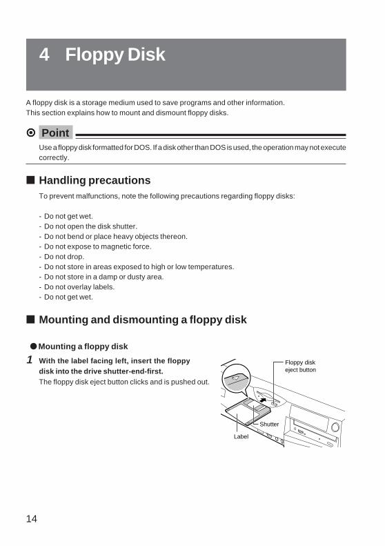
A floppy disk is a storage medium used to save programs and other information.This section explains how to mount and dismount floppy disks.
¤¤¤¤¤ PointUse a floppy disk formatted for DOS. If a disk other than DOS is used, the operation may not executecorrectly.
■ Handling precautionsTo prevent malfunctions, note the following precautions regarding floppy disks:
- Do not get wet.- Do not open the disk shutter.- Do not bend or place heavy objects thereon.- Do not expose to magnetic force.- Do not drop.- Do not store in areas exposed to high or low temperatures.- Do not store in a damp or dusty area.- Do not overlay labels.- Do not get wet.
■ Mounting and dismounting a floppy disk
● Mounting a floppy disk
1 With the label facing left, insert the floppydisk into the drive shutter-end-first.The floppy disk eject button clicks and is pushed out.
4 Floppy Disk
Floppy disk eject button
Shutter
Label

15
● Dismounting a floppy disk
1 Confirm that the floppy disk access indicatorlamp is off.
¤¤¤¤¤ PointTo prevent data from being destroyed, do not dismount a floppy disk from the drive when the floppydisk access indicator lamp is on.
2 Press the floppy disk eject button.The floppy disk is ejected.
Floppy disk access indicator lamp

16
Your PC incorporates a CD-ROM drive(depending on the model).This section explains how to handle, mount, and dismount CD-ROM disks.
■ Handling precautions
To prevent malfunctions, note the following precautions regarding CD-ROM disks:
- Do not write on the label side (printed side) using a ball-point pen or pencil and donot affix extra labels.
- Do not touch or scratch the data side.- Do not bend or place heavy objects thereon.- Clean using a dry soft cloth (do not use a cleaning solution).- Do not get wet.- Do not store in areas exposed to high or low temperatures.- Do not store in damp or dusty areas.
¤¤¤¤¤ PointCD-ROMs (developed from music compact disks (CD)) are used to save PC information (suchas characters). The term "ROM" stands for "Read Only Memory," which means that the user canonly read data in the disk. The PC can read data from a CD-ROM disk but cannot write data ontoa disk.
The PC can read CD-ROM disks having the following markings:
5 CD-ROM
COMPACT COMPACT
DIGITAL AUDIO
COMPACT
DIGITAL AUDIO
COMPACT
DIGITAL VIDEO

17
■ Mounting and dismounting a CD-ROM disk
● Mounting a CD-ROM
1 Press the EJECT button.The CD-ROM tray is ejected.
2 With the label side of the CD-ROM diskfacing up, place the CD-ROM disk in thecenter of the tray.
3 Press the EJECT button.
The tray retracts into the PC main unit and the CD-ROM is set.
¤¤¤¤¤ Point- When the CD-ROM is set, the BUSY lamp goes on. When the BUSY lamp goes off, proceed to
the next step.- Pressing the EJECT button when inserting the tray does not set the tray correctly.
● Dismounting a CD-ROM
To dismount a CD-ROM disk, confirm that the BUSY lamp is off, then press the EJECT button asshown above.
BUSY lamp
EJECT button
Label side
Tray

18
Your PC incorporates a built-in hard disk. This section outlines precautions to take when handling ahard disk.
■ What is a hard disk?A hard disk is used to save software and other data andconsists of a magnetic disk packed in a box as shownon the right. A hard disk can save more data and canread and write data faster than is possible with floppydisks.
■ Handling precautionsTo prevent malfunctions, note the following precautions regarding hard disks:
- Do not move or subject the PC to shock and/or vibration with its power on.- Do not expose to extreme temperature changes.- Do not place in areas exposed to direct sunlight or near heating units.- Do not store in areas subjected to shock or vibration.- Do not store in damp or dusty areas.- Do not expose to a strong magnetic field.- Do not disassemble or remodel.- Do not get wet.
¤¤¤¤¤ Point- Because incorrect handling may destroy data in a hard disk, back up all necessary data.- Because there is a difference in the storage capacity of same-type hard disks, back up data for
each file or segment, not for each hard disk.
6 Hard Disk

Chapter 3 Installing Internal
OptionsThis chapter explains how to install internal options such as hard disk andexpansion cards.
Consult this chapter as required.
3

20
The features and performance of your PC can be upgraded by installing options. This section describesthe types of internal options that can be installed in the PC and explains how to remove the uppercover and front panel in preparation for installing the internal options.
■ Handling precautionsNote the following when installing internal options:
- Before starting operation, switch off the PC and all connected peripherals and unplug powercords from the AC outlets.
- Immediately after the PC is turned off, internal components and units of the PC are hot. Wheninstalling and removing internal options, turn off the power and allow the PC to cool down forabout 10 minutes before starting operation.
- Do not disassemble the power supply unit (a box-shaped device inside the PC).
- Do not damage or remodel internal cables or units.
- Because internal options are PC boards with exposed soldered sections that may be damagedby a static electrical charge, discharge any accumulated static electricity before handling.
- Secure the board by the metal bracket portions or an edge of the PC board such that the surfaceof the PC board and the soldered sections are not handled.
- Installation and disassembly of options other than Fujitsu brand products void the warranty.
1 Introduction

21
■ Installing positions of internal options
Built-in hard disk (standard)Replacing a hard disk with larger capacity increases the storage capacity of the PC.
3.5-inch file bayInstall 3.5-inch file bay options.The usual devices installed are as follows.- Hard disk (IDE standard, SCSI standard)- Magneto-optic disk drive- 3.5-inch floppy disk drive
Expansion card slotExpansion cards extend the range of the features of the PC.For example, installing a SCSI card enables the use of a SCSI-standard hard disk and a magneto-optical disk drive.
Memory slotInstall the memory.Memory expansion increases the amount of data to be stored at one time and enhances the throughput of the PC.
5-inch file bayInstall 5-inch file bay options (upper/lower bays)The usual devices installed are as follows.- CD-ROM drive- 5-inch floppy disk drive- Hard disk

22
■ Removing the upper coverWhen installing internal options, remove the upper cover so as to reveal the inside of the mainunit.
1 Remove three screws at the rear of the PCmain unit.
2 Remove the upper cover.
Slide the upper cover to the rear of the PC mainunit (in the direction of arrow 1 in the figure)
Lift and remove the cover (in the direction ofarrow 2 in the figure).
¤¤¤¤¤ Point- To replace the cover, reverse the above procedure.
- If the upper cover of the PC main unit is left removed, the internal battery life will shorten. Keepthe duration when the upper cover is left removed at minimum requirement such as only forinstalling internal options.
■ Removing the front panelRemove the front panel when installing internal options in file bays. (Removal of the front panel isnot required when installing a hard disk in a 3.5-inch file bay.)
1 Release hooks in order from 1 to 4 andpull out the front panel.
¤¤¤¤¤ PointTo attach the front panel, secure the hooks in order from 1 to 4 in the figure.
2
1
1
2 4
3

23
¤¤¤¤¤ PointTo install a memory module, set up the PC, turn off the power, remove the AC power cord fromthe outlet and install the memory module.
WARNING● To prevent electric shock, before installing and removing memory modules,
turn off the PC and connected units and unplug power cords from respectiveoutlets.
● To prevent electric shock, fire, and/or malfunction, install only Fujitsu brandmemory modules in the PC.
CAUTION● To prevent personal injury and/or malfunction, when installing and removing
memory modules, only remove screws from specified locations.
● To prevent injury and/or malfunction, do not touch PC board components notspecified.
Electric shock
Electric shock
Injury
Injury
2 Installing Memory Modules
This section explains how to install and remove additional memory modules. Memory expansion inyour PC increases the amount of data to be read and enhances the throughput of the PC.
DIMM 1
DIMM 2

24
■ MemoryA total of up to 512 megabytes of memory modules can be installed.A memory module has been installed in DIMM1 as standard.Install a memory module to be added in DIMM2.To ensure a total of 512 megabytes of memory, replace the memory module in DIMM1 with a256-megabyte memory module.
¤¤¤¤¤ PointInstall a Fujitsu genuine memory module to ensure PC operation.
■ Installing an additional memory
1 Remove the upper cover.
2 Push down the hooks at both ends of theslot.
3 Insert the memory card into the slot.
Insert the memory module vertically whilealigning the memory module notches and thesocket keys. The hooks at both ends of the slotare raised. Confirm that the memory card issecurely locked in place.
4 Attach the upper cover.Notch

25
■ Removing the memory
1 Remove the upper cover.
2 Open the hooks out at both ends of the slotand remove the memory module.
¤¤¤¤¤ PointNote that opening the hooks out forcefully causes the memory card to pop out of the slot and maycause a malfunction.
3 Attach the upper cover.

26
¤¤¤¤¤ Point- To install an expansion card, set up the PC, turn off the power, and install the expansion card.- The first to fourth white slots from the top are for PCI cards.- Only a half-size expansion card can be installed in the first slot from the top.- When an expansion card using a serial port such as a modem card is installed, change the
duplicated serial port to "Not used" in the BIOS setup.
WARNING
● To prevent electric shock, before installing and removing expansion cards,turn off the PC and connected units and unplug power cords from respectiveoutlets.
● To prevent electric shock, fire, and/or malfunction, install only Fujitsu brandexpansion cards in the PC.
CAUTION
● To prevent injury, when installing and removing expansion cards, removescrews only from specified locations.
Electric shock
Injury
3 Installing Expansion Cards
This section explains how to install expansion cards, which extend the range of the features ofyour PC.
PCI bus
PCI bus

27
● To prevent injury and/or malfunction, do not touch PC board components notspecified.
● To prevent injury and/or device failure, do not touch the metal bracket on themotherboard at the rear of the PC main unit.
To install expansion cards, "resources" must be set.The floppy disk drive or hard disk drive inside the PC uses predetermined paths specific to thosedevices when transferring data with the CPU and memory.These paths include I/O port addresses, DMA channels, and interrupt levels (IRQ), which aregenerally called "resources."
Before installing expansion cards, read the following descriptions.
■ Expansion cards for PCI bus (Plug & Play compatible cards)When PCI bus expansion cards are installed, resources are set automatically.Card installation procedures differ depending on the operating system.Card installation procedure:For PCs using Windows 98,( see "Expansion card installation procedure for a PC using Windows 98 on page 28)For PCs using Windows NT,( see "Expansion card installation procedure for a PC using Windows NT on page 29)
Injury
28
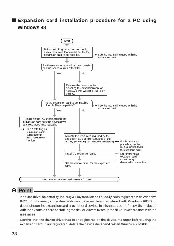
¤¤¤¤¤ Point- A device driver selected by the Plug & Play function has already been registered with Windows
98/2000. However, some device drivers have not been registered with Windows 98/2000,depending on the expansion card or peripheral device. In this case, use the floppy disk includedwith the expansion card containing the device drivers to set up the driver in accordance with themessages.
- Confirm that the device driver has been registered by the device manager before using theexpansion card. If not registered, delete the device driver and restart Windows 98/2000.
Start
Before installing the expansion card, check resources that can be set for the expansion card to be installed.
Are the resources required by the expansion card unused resources of the PC?
See the manual included with the expansion card.
See the manual included with the expansion card.
Allocate the resources required by the expansion card to idle resources of the PC (by pin setting for resource allocation).
Set the device driver for the expansion card.
For the allocation procedure, see the manual included with the expansion card.
Install the expansion card. See "Installing an expansion card" subsequently described in this section.
Yes No
Yes No
Release the resources by disabling the expansion card or hardware that will not be used by the PC.
Is the expansion card to be installed Plug & Play compatible?
End. The expansion card is ready for use.
Turning on the PC after installing the expansion card sets the device drive and resources automatically.
See "Installing an expansion card" subsequently described in this section.
■ Expansion card installation procedure for a PC usingWindows 98
29
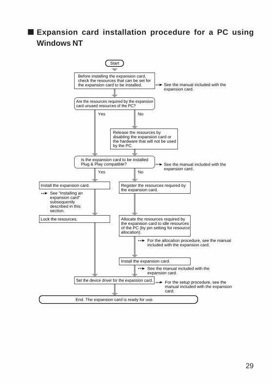
Start
Before installing the expansion card, check the resources that can be set for the expansion card to be installed.
Are the resources required by the expansion card unused resources of the PC?
See the manual included with the expansion card.
See the manual included with the expansion card.
Allocate the resources required by the expansion card to idle resources of the PC (by pin setting for resource allocation).
Install the expansion card.
Set the device driver for the expansion card.
Install the expansion card. Register the resources required by the expansion card.
Yes No
Yes No
Release the resources by disabling the expansion card or the hardware that will not be used by the PC.
End. The expansion card is ready for use.
See "Installing an expansion card" subsequently described in this section.
Lock the resources.
For the allocation procedure, see the manual included with the expansion card.
See the manual included with the expansion card.
For the setup procedure, see the manual included with the expansion card.
Is the expansion card to be installed Plug & Play compatible?
■ Expansion card installation procedure for a PC usingWindows NT

30
■ Starting and terminating the ICU (For a PC using Windows NT)This section explains how to start and terminate the ICU using Windows NT.
1 If the PC is turned on, turn it off.
2 Confirm that the "boot disk" is in write-enable status, insert in the floppy disk drive, thenturn on the PC.MS-DOS is started.
3 Confirm that the "Plug and Play kit for MS-DOS(R) ICU R1.21 disk 1" is in write-enable status,replace the disk with the "boot disk", then enter the following character string and pressthe [Enter] key:
The ICU is started.
¤¤¤¤¤ Point- Do not remove the "Plug and Play kit for MS-DOS(R) ICU R1.21 disk 1" from the floppy disk
drive when using the ICU.- Use the keyboard for all ICU operations.- Do not set the PCI devices to "Disabled" with the ICU. The devices may not be reset to "Enabled."
4 Set up the resources.
When resource setup is terminated, terminate the ICU.
5 Press [Alt]+[F].The pull-down menu appears.
6 Select the "Exit" command and press the [Enter] key.
7 Turn off the PC main unit.
icu

31
■ Installing an expansion cardTo install a large expansion card, remove the motherboard as shown in step 3. To install a smallexpansion card, steps 2, 3, 7, and 8 are not required.
1 Remove the upper cover.
2 Remove the retaining metal bracket at theside (for installing a large expansion card).
Remove the screw, open the retaining metalbracket in the direction of arrow 1 , and removethe bracket in the direction of arrow 2 .
3 Slide the motherboard (for installing asmall expansion card).
Raise the lever about 90 degrees and pull outthe motherboard.
4 Remove the slot cover.
Remove the screw to remove the retaining metalbracket, then remove the slot cover to install theexpansion card.
5 Insert the expansion card into theconnector.
Insert the expansion card firmly into theconnector.
12
Lever
Expansion slotExpansion card terminal
32
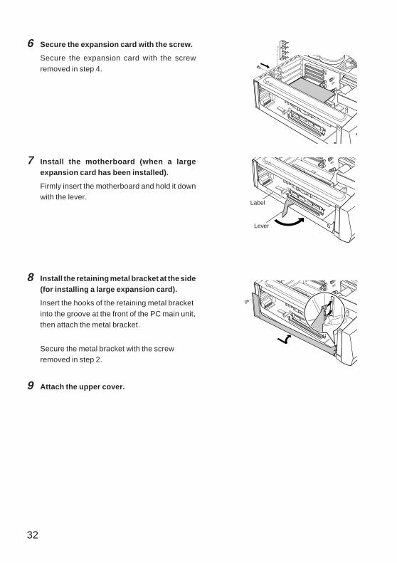
6 Secure the expansion card with the screw.
Secure the expansion card with the screwremoved in step 4.
7 Install the motherboard (when a largeexpansion card has been installed).
Firmly insert the motherboard and hold it downwith the lever.
8 Install the retaining metal bracket at the side(for installing a large expansion card).
Insert the hooks of the retaining metal bracketinto the groove at the front of the PC main unit,then attach the metal bracket.
Secure the metal bracket with the screwremoved in step 2.
9 Attach the upper cover.
Lever
Label

33
This section explains how to install expansion bay options such as internal hard disk, magneto-opticdisk drive, CD-ROM drive, and floppy disk drive. The power can be supplied from the PC main unit tothe expansion bay options, differing from external-type devices; therefore, an outlet is not required.This is also useful in saving space.
¤¤¤¤¤ Point- To install expansion bay options, set up the PC, turn off the power, and then install the options.- The internal hard disk supporting Ultra DMA/66 can be used by setting it to Ultra DMA/66.
To connect a hard disk not supported by Ultra DMA/33, be sure to set the DMA to OFF. If the PCis used while the DMA is set to ON by mistake, it may malfunction and data may be lost.Consult with the user's guide that comes with the hard disk, to check whether the additionalhard disk supports Ultra DMA/33.
- On the secondary IDE side, Ultra DMA/33 is not supported.- Use the CD-ROM drive, equipped as a standard feature, without modifying its connection to the
secondary IDE. To add a hard disk or magneto-optic disk drive to the secondary IDE, reconnectthe hard disk or magneto-optic disk drive to the master connector and reconnect the CD-ROMto the slave connector.
4 Installing Expansion Bay Options

34
WARNING
● To prevent an electric shock, turn off the PC and connected units and unplugpower cords from respective outlets before installing internal options in, orremoving them from the expansion bay.
● To prevent an electric shock, fire, and/or malfunction, install only Fujitsugenuine internal options in the PC expansion bay.
CAUTION
● To prevent personal injury and/or malfunction, remove screws only from thelocations specified when installing internal bay options in, or removing themfrom the expansion bay.
● To prevent injury and/or malfunction, do not touch any components inlocations on the PC board that are not mentioned in any of the relevantdocuments.
Electric shock
Electric shock
Injury
Injury

35
■ Replacing a internal hard disk equipped as standardThis section explains how to replace a standard-equipped internal hard disk with a hard disk oflarger capacity.
1 Set up the jumper switch.See the manual accompanying the internal harddisk and make sure that the jumper switch hasbeen set to master, or cable select.
2 If retaining metal brackets are mounted onboth sides of the internal hard disk to bereplaced, remove them.Remove the screws (4) to remove the retainingmetal brackets.
3 Remove the upper cover.
4 Disconnect the hard disk cables.
Disconnect the power cord and flat cablesconnected to the hard disk.
5 Remove the retaining metal bracket.
Remove the screw (one), then remove theretaining metal bracket by sliding it in thedirection of arrow 1 , then arrow 2 , and then liftit in the direction of arrow 3 . 2
13
36
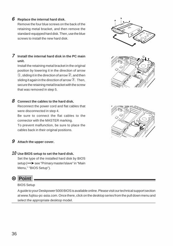
6 Replace the internal hard disk.Remove the four blue screws on the back of theretaining metal bracket, and then remove thestandard-equipped hard disk. Then, use the bluescrews to install the new hard disk.
7 Install the internal hard disk in the PC mainunit.Install the retaining metal bracket in the originalposition by lowering it in the direction of arrow1 , sliding it in the direction of arrow 2 , and thensliding it again in the direction of arrow 3 . Then,secure the retaining metal bracket with the screwthat was removed in step 5.
8 Connect the cables to the hard disk.Reconnect the power cord and flat cables thatwere disconnected in step 4.Be sure to connect the flat cables to theconnector with the MASTER marking.To prevent malfunction, be sure to place thecables back in their original positions.
9 Attach the upper cover.
10 Use BIOS setup to set the hard disk.Set the type of the installed hard disk by BIOSsetup ( see "Primary master/slave" in "MainMenu," "BIOS Setup").
¤¤¤¤¤ PointBIOS Setup
A guide to your Deskpower 5000 BIOS is available online. Please visit our technical support sectionat www.fujitsu-pc-asia.com. Once there, click on the desktop series from the pull down menu andselect the appropriate desktop model.
2
31

37
■ Installing internal options to 3.5-inch expansion baysThis section explains how to install 3.5-inch expansion bay options such as a 3.5-inch internalhard disk, magneto-optic disk drive, and 3.5-inch floppy disk drive. A magneto-optic disk driveis used below in an installation example.
1 Set the internal option.See the manual accompanying the internal
options to set the following items.- To install an IDE-standard internal option:
Set the master, slave, and cable selection.- To install a SCSI interface internal option:
Set the SCSI ID.
2 If retaining metal brackets are mounted onboth sides of the internal hard disk to beinstalled, remove them.
Remove the screws (four) to remove theretaining metal brackets.
3 Remove the upper cover.
4 Remove the front panel.
The front panel does not need to be removedwhen installing a hard disk.
5 Remove the blank panel.
Remove the screw (one) to remove the blankpanel.
The blank panel does not need to be removedwhen installing a hard disk.
PQ
RS
TU
VW
OFF

38
6 Remove the retaining metal bracket from thePC main unit.Slide the retaining metal bracket toward the rearside of the PC main unit, and then lift and removethe retaining metal bracket.
7 Install a internal option in the retaining metalbracket.Secure the internal option with the four screws
that were removed in step 2.- To install a magneto-optic disk drive:
Install the magneto-optic disk drive in position1 in the figure.
- To install a hard disk:Install the hard disk drive in position 2 in thefigure.Use the blue screws accompanying theinternal options to secure the hard disk.
8 Install the internal option in the PC main unit.Slide the internal option toward the front side andinstall it.
1
2
39
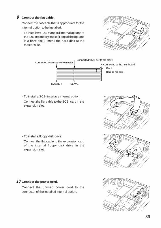
9 Connect the flat cable.
Connect the flat cable that is appropriate for theinternal option to be installed.
- To install two IDE-standard internal options tothe IDE secondary cable (if one of the optionsis a hard disk), install the hard disk at themaster side.
- To install a SCSI interface internal option:
Connect the flat cable to the SCSI card in theexpansion slot.
- To install a floppy disk drive:
Connect the flat cable to the expansion cardof the internal floppy disk drive in theexpansion slot.
10 Connect the power cord.
Connect the unused power cord to theconnector of the installed internal option.
Connected to the riser board
Connected when set to the slaveConnected when set to the master
SLAVEMASTER
Blue or red linePin 1

40
11 Attach the front panel.Remove the blank panel for a 3.5-inchexpansion bay from the rear side of the frontpanel as required in the arrow direction shownin the figure.
12 Attach the upper cover.
13 Use BIOS setup to configure the internaloption.
To configure the installed IDE-standard internaloption, use the main menu of BIOS setup (see "Main Menu,""BIOS Setup").
¤¤¤¤¤ PointTo remove the internal option, reverse the above procedure.
¤¤¤¤¤ PointBIOS Setup
A guide to your Deskpower 5000 BIOS is available online. Please visit our technical supportsection at www.fujitsu-pc-asia.com. Once there, click on the desktop series from the pull downmenu and select the appropriate desktop model.
3-inch blank panel
HookBend the hook inward.
Rear of the panel

41
■ Installing internal options to 5-inch expansion baysThis section explains how to install 5-inch expansion bay options such as CD-ROM drive and 5-inch floppy disk drive. A CD-ROM drive is used below in an example of installation. Up to two 5-inch expansion bay options can be installed in your PC.
¤¤¤¤¤ PointThe retaining metal bracket is required for installing a 3.5-inch hard disk or magneto-optic diskdrive.
Retaining metal bracket
1 Configure the internal option.
See the manual accompanying the internal options to configure the following items.
- To install an IDE-standard internal option:
Set the master, slave, and cable select.
- To install a SCSI interface internal option:
Configure the SCSI ID.
2 Remove the upper cover.
3 Remove the front panel.
4 Remove the blank panel (for installing theinternal option to the lower 5-inch expansionbay).Remove a screw to remove the blank panel.
5 Insert the internal option from the front sideof the PC main unit

42
6 Secure the internal option with two screws.
7 Connect the flat cable.Connect the flat cable appropriate for the internaloption to be installed.- To install an IDE-standard internal option,
connect the flat cable to the master or slaveconnector according to the setting of theinternal option.If a magneto-optic disk has been installed bya custom-made specification, connect themagneto-optic disk drive to the masterconnector and the other internal option to theslave connector. However, to install a harddisk, connect the hard disk to the masterconnector and connect the magneto-optic diskdrive to the slave connector.
- To install a SCSI interface internal option:Connect the flat cable to the SCSI card in theexpansion slot.
Connected to the riser board
Connected when set to the slaveConnected when set to the master
SLAVEMASTER
Blue or red linePin 1
43
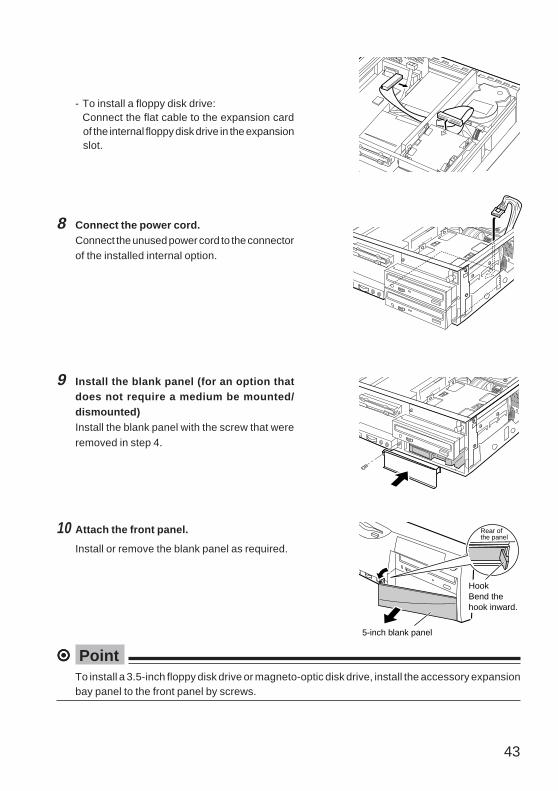
8 Connect the power cord.Connect the unused power cord to the connectorof the installed internal option.
9 Install the blank panel (for an option thatdoes not require a medium be mounted/dismounted)Install the blank panel with the screw that wereremoved in step 4.
10 Attach the front panel.
Install or remove the blank panel as required.
¤¤¤¤¤ PointTo install a 3.5-inch floppy disk drive or magneto-optic disk drive, install the accessory expansionbay panel to the front panel by screws.
Rear of the panel
5-inch blank panel
HookBend the hook inward.
- To install a floppy disk drive:Connect the flat cable to the expansion cardof the internal floppy disk drive in the expansionslot.
44
11 Attach the upper cover.
12 Use BIOS setup to configure the internal option.
To configure the IDE-standard installed internal option, use the main menu of BIOS setup( see "Main Menu," "BIOS Setup").
¤¤¤¤¤ PointBIOS Setup
A guide to your Deskpower 5000 BIOS is available online. Please visit our technical support sectionat www.fujitsu-pc-asia.com. Once there, click on the desktop series from the pull down menu andselect the appropriate desktop model.
45
Chapter 4 TroubleshootingThis chapter explains the procedure to follow if the computer does not operateas expected.
5

46
This section provides a list of error messages and suitable responses thereto. Consult this sectionas required.
■ Error messages displayed by the PC
Error Message
An error occurred at address
xxxx during a system memory
test.
An error occurred at address
xxxx during an additional
memory test.
System cache error-Cache
disabled
An error occurred during a
keyboard controller test.
An error occurred during a
keyboard test.
An error occurred during a
floppy disk drive test.
Description and necessary action
If an extended RAM module is used, remove the
module and determine whether the error recurs. If this
message is not displayed, an extended RAM module
error is expected. Replace with another extended
RAM module and determine whether the error recurs.
If the error recurs, contact a dealer or the Fujitsu
service center.
Confirm that the extended RAM module is mounted
properly and is a Fujitsu product. If the error recurs,
contact a dealer or the Fujitsu service center.
contact a dealer or the Fujitsu service center.
Set the MAIN switch to OFF, then wait ten seconds
and set to ON again. If the message is still displayed,
contact a dealer or the Fujitsu service center.
If an external keyboard is connected, confirm that it is
connected correctly and turn on the power again. If
this message is still displayed, contact a dealer or the
Fujitsu service center.
Confirm that 'Floppy Disk Drive A' is set properly on
the BIOS setup main menu and that the floppy disk
drive is mounted correctly.
1 Error Messages
47
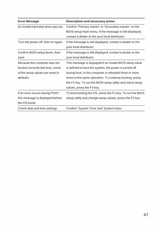
Error Message
An invalid hard disk drive was set.
Turn the power off, then on again.
Confirm BIOS setup items, then
save.
Because the computer was not
booted correctly last time, some
of the setup values are reset to
defaults.
If an error occurs during POST,
this message is displayed before
the OS boots.
Check date and time settings
Description and necessary action
Confirm ‘Primary master’ or ‘Secondary master’ on the
BIOS setup main menu. If the message is still displayed,
contact a dealer or the your local distributor.
If the message is still displayed, contact a dealer or the
your local distributor.
If the message is still displayed, contact a dealer or the
your local distributor.
This message is displayed if an invalid BIOS setup value
is defined to boot the system, the power is turned off
during boot, or the computer is rebooted three or more
times in the same operation. To continue booting, press
the F1 key. To run the BIOS setup utility and check setup
values, press the F2 key.
To boot booting the OS, press the F1 key. To run the BIOS
setup utility and change setup values, press the F2 key.
Confirm 'System Time' and 'System Date.'

48
Error Message
Invalid system disk
Non-System disk or disk error
Operating system not found
An error occurred during
execution of the Execution
Environment.
An error occurred during
execution of the Preboot
Execution Environment.
An error occurred during
execution of the Preboot
Execution Environment.
An error occurred during
execution of the Preboot
Execution Environment.
An error occurred during
execution of the Preboot
Execution Environment.
An error occurred during
execution of the Preboot
Execution Environment.
Description and necessary action
Replace the disk, and then press any key
This message is displayed when the PC is switched
on while a floppy disk other then a system disk is set in
the floppy disk drive. Remove the floppy disk and
press any key.
Replace and press any key when ready
This message is displayed when the PC is switched
on while a floppy disk other then a system disk is set in
the floppy disk drive. Remove the floppy disk and
press any key.
OS cannot be found. Confirm that the drive is
correctly set at BIOS setup or the OS is installed in the
specified drive.
The LAN cable is not correctly connected. Connect
the LAN cable correctly.
The IP address required to boot the PC was not
obtained. Set the boot server correctly, or set 'Boot
from the network server' to Disabled on the BIOS
setup menu.
The boot filename was not obtained from the boot
server. Set the boot server correctly, or set 'Boot from
the network server' to Disabled on the BIOS setup
menu.
There is no boot server, or the boot server does not
work correctly. Set the boot server correctly, or set
'Boot from the network server' to Disabled on the
BIOS setup menu.
The boot image file on the boot server was not
obtained. Set the boot server correctly, or set 'Boot
from the network server' to Disabled on the BIOS
setup menu.
Booting from a network failed. Set the boot server
correctly, or set 'Boot from the network server' to
Disabled on the BIOS setup menu.
49
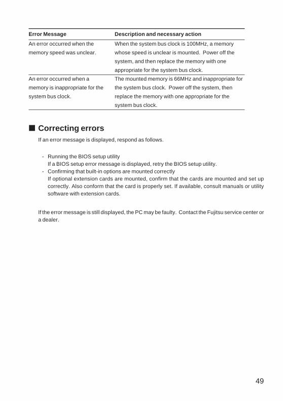
■ Correcting errorsIf an error message is displayed, respond as follows.
- Running the BIOS setup utilityIf a BIOS setup error message is displayed, retry the BIOS setup utility.
- Confirming that built-in options are mounted correctlyIf optional extension cards are mounted, confirm that the cards are mounted and set upcorrectly. Also conform that the card is properly set. If available, consult manuals or utilitysoftware with extension cards.
If the error message is still displayed, the PC may be faulty. Contact the Fujitsu service center ora dealer.
Error Message
An error occurred when the
memory speed was unclear.
An error occurred when a
memory is inappropriate for the
system bus clock.
Description and necessary action
When the system bus clock is 100MHz, a memory
whose speed is unclear is mounted. Power off the
system, and then replace the memory with one
appropriate for the system bus clock.
The mounted memory is 66MHz and inappropriate for
the system bus clock. Power off the system, then
replace the memory with one appropriate for the
system bus clock.

50
This section provides troubleshooting information for each function. Consult this section as required.For troubleshooting information for Windows NT, refer to the Windows NT manual or the online helpregistered on the Start menu.
■ Troubleshooting information on the computer main unit andperipheral units
● The access lamp does not light up.The PC may be faulty. Contact a dealer or the Fujitsu service center.
● No data is displayed on the screen.Confirm the following:- Is the Power switch on the display turned on?- Is the power savings mode selected?
Move the mouse or press any key.- Is the display cable connected correctly? See page 2 "Installation" to connect the display cable
correctly.- Is the power cable of the display unit connected to the outlet? See page 2 "Installation" to
connect the power cable correctly.
WARNING
● Before connecting cables, turn off the power to prevent electric shock.
- Are the brightness and contact variable resistors on the CRT display unit adjusted correctly?Adjust the screen image using the brightness and contact variable resistors.
● The screen flickers.Is there any strong magnetic field in the vicinity of the computer, such as a TV set? If so, keepaway from the PC.
● The screen sides are cut.Adjust the horizontal screen size using the adjustment controls on the CRT display unit.
● Data cannot be read from or written to floppy disks.Check the following:- Is the floppy disk drive head dirty? Clean the head using a cleaning disk.- Is the floppy disk write-protected? Move the write-protect tab on the floppy disk to a the write-
enabled position.
Electric shock
2 Troubleshooting

51
● The power is not turned on or the Power lamp on the front panel
does not light up.Is the power cable plugged in?
● Data cannot be read from the CD-ROM drive.Check the following:- Has the CD-ROM been placed properly at the center of the tray? Place the CD-ROM on the tray
again with the label side facing upward.- Has the CD-ROM been placed upside down on the tray? Place the CD-ROM on the tray in the
proper manner with the label side facing upward.- Is the CD-ROM dirty or wet? Clean the CD-ROM with a soft dry cloth (moving from the center to
the periphery).- Is the CD-ROM damaged? Replace the CD-ROM.- Does the CD-ROM conform to the required standard? Use a correct CD-ROM.
● Characters entered using the keyboard are not displayed.Is the keyboard connected correctly? See page 2, "Installation" to connect the display cablecorrectly.
● The mouse cursor does not move.Is the mouse connected correctly? See page 2, "Installation" to connect the display cable correctly.
■ Troubleshooting information on Windows 98
● The entire Windows 98 programs are frozen during the execution of an appli-
cation.First press the Ctrl + alt + Delete keys to end the application. If the application cannot be terminated,press the Ctrl + Alt + Delete key twice to reboot the computer. If the computer cannot be rebooted,press the Power switch to turn off the power, then reboot a few minutes later. After the computeris rebooted, from the Start menu, select Program - Accessories - System tools, then click on Scandisk.If no error is detected by the scan disk utility, continue operation. If an error is detected, respondin accordance with the messages displayed.However, the error might happen again after it hasbeen corrected. If the error recurs, attempt to reinstall Windows 98 or applications.
¤¤¤¤¤ PointThe current operation data by an application is not saved if the application is terminated usingthe Ctrl + Alt + Delete keys or the computer is reset.

52
● The mouse is disabled and Windows 98 cannot end.Use the keyboard to exit Windows 98 as follows:
1 Press the key or the Ctrl + Esc keys.
The Start menu appears.2 Select "Exit Windows" with the ↑" or ↓ key and press the Enter key.
The Exit Windows dialog box is displayed.3 Select "Turn off power" and press the Enter key.
Windows 98 ends.
● A SCSI unit is connected using a SCSI card but cannot be identified by
Windows 98.Check the following:- Is the SCSI card driver installed correctly? Proceed as follows.
1 From the Start menu, select Setup and click on Control Panel.The Control panel window is displayed.
2 Double click on the System icon.3 Click on the Device manager tab and confirm that the SCSI controller is defined.
If not defined, click on the Hardware icon in the Control Panel window to detect a SCSI cardand install the driver.
- Is the SCSI unit turned on before the computer is turned on? If the computer is turned on beforethe SCSI unit is turned on, the SCSI unit cannot be identified.
■ If an error recurs
If the cause is still unknown or the system cannot be reset, contact a dealer or the Fujitsu servicecenter. Then check and record the following:
- Model name and serial number of the computer (See the label at the rear of the computer.)- OS and version used- Types of extension cards and memory installed- Circumstances (the particulars, including the messages displayed on the screen, etc.)- Date and time an error occurred

AppendixThis appendix explains how to clean the PC and provides PC main unitspecifications.

54
This section explains the name and function of each component of the PC main unit, motherboard/riser board, and keyboard.
■ Front of the PC main unit
1 Name and Function of EachComponent
Sound volumeThe sound volume of speakers and headphones can be controlled.
Headphone terminalConnect a headphone.
USB connectorConnect the USB device.Keep the cover closed when not used.
Power lampThe lamp comes on while the PC main unit is on.
Hard disk access indicator lampThe lamp comes on while accessing a hard disk.
Floppy disk access indicator lampThe lamp comes on while accessing a floppy disk.
Floppy disk driveMount a floppy disk in this drive to write data into or read data from a floppy disk.

55
Headphone terminal (Only for a music CD)
Headphone volume (Only for a music CD)
Floppy disk eject buttonPress this button to eject a floppy disk.
3.5-inch blank panelRemove this panel to add a 3.5-inch internal option.
BUSY lampThe lamp is on while reading data from a CD-ROM or playing a music CD.
EJECT buttonPress this button to mount or dismounta CD-ROM or a music CD. This button can be used while the PC main unit is on.
5-inch blank panelRemove this panel to add a 5-inch internal option.
CD-ROM driveUse this drive to read a program from a CD-ROM disk or play a music CD.
Power switchPress this switch to turn on the PC main unit, put the system into the standby status, or recover the system from the standby status.
Microphone terminalConnect a microphone.

56
■ Rear of the PC main unit
OutletConnect the power cord of the CRT display.
Ventilation holesThe heat within the PC main unit is ventilated through these holes. Keep them free.
Power-switching switch
InletConnect the power cord of the PC main unit.
SPK OUT terminalConnect the speakers.
LINE IN terminalConnect the output terminal of audio equipment.
LINE OUT terminalConnect the input terminal of audio equipment.

57
USB connectorConnect the peripherals conforming to the USB standard.
LAN connector ( : NETWORK)Connect the LAN cable.
2
1
Mouse connector ( : MOUSE)The heat within the PC main unit is ventilated through these holes. Keep them free.
DVI ConnectorConnect the display cable conforming to DVI standard
Serial connector ( : SERIAL PORT1)( : SERIAL PORT2)Connect a RS-232C interface device such as a modem.
Ventilation holesThe heat within the PC main unit is ventilated through these holes. Keep them free.
Security lockYou can connect a security-use cable bought on the market.
CRT connector ( : MONITOR)Connect the CRT cable.
Parallel connector ( : PRINTER)Connect the printer cable. It is also called a parallel port.
Keyboard connector ( : KEYBOARD)Connect the keyboard cable.
58
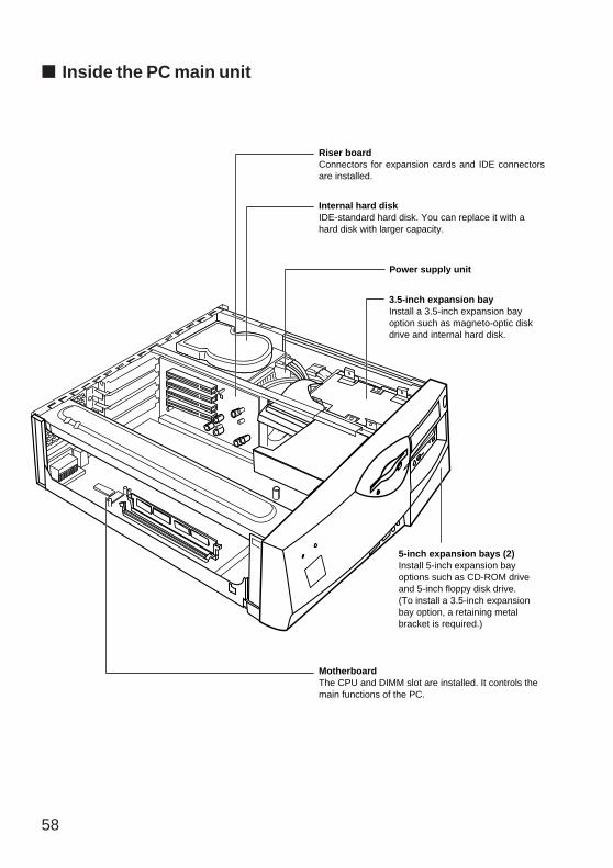
Riser boardConnectors for expansion cards and IDE connectors are installed.
3.5-inch expansion bayInstall a 3.5-inch expansion bay option such as magneto-optic disk drive and internal hard disk.
5-inch expansion bays (2)Install 5-inch expansion bay options such as CD-ROM drive and 5-inch floppy disk drive.(To install a 3.5-inch expansion bay option, a retaining metal bracket is required.)
MotherboardThe CPU and DIMM slot are installed. It controls the main functions of the PC.
Internal hard diskIDE-standard hard disk. You can replace it with a hard disk with larger capacity.
Power supply unit
■ Inside the PC main unit

59
■ Motherboard/riser board
JP3 jumper switchSet whether to enable the password.
Internal batteryThe battery is used to store the setup of the PC. The life span of the battery is about five years under normal use condition (8 hours per day). If the upper cover of the PC main unit is left removed, the internal battery life will shorten. Keep the duration when the upper cover is left removed at minimum requirement such as only for installing internal options.
Secondary IDE connector
Primary IDE connectorConnect the hard disk for starting the operating system.
: Position of pin 1
DIMM slotInsert a memory module.The slots are placed in the order of DIMM1 and DIMM2 from the right.
Expansion slotInsert various option cards to extend the functions of the PC.The slots are placed in the order of ISA1 (half), ISA2 (full), PCI1 (full), and PCI2 (full) from the right.
CPU
Floppy disk drive connector

60
■ PC main unit specifications
Product name
CPU
BIOS ROM
System RAM
Floppy disk
Hard disk
CD-ROM
Graphics
Sound
I/F CRT
USB
Keyboard
Mouse
Serial port
Parallel port
LAN
Audio
Error monitorfunction
Number of expansionslots
DESKPOWER 5000
Pentium III or Celeron
512 KB (FLASH ROM)
SDRAM DIMM with 168-pin parity (Supporting ECC)Up to 512 MB
3.5-inch disk drive x 1
10.2/20.4GB (Ultra DMA66) or higher capacity
Optional
Intel 810E with DVMT
Crystal 4281 + 4297A (Integrated PCI)
VGA/SVGA D-SUB 15 pin
2 ports (4 pins) (One of the ports is on the front.)
PS/2 type Mini DIN 6 pin
PS/2 type Mini DIN 6 pin
Asynchronous RS-232C x 2 D-SUB 9 pin
Conforming to Centronics D-SUB 25 pin
Intel 82559 100 BASE-TX/10 BASE-T (WAKEUP ON LAN functionprovided)
Front: Microphone input, headphone outputRear: Line input, line output, speaker output
CPU fan stop/CPU temperature error/voltage abnormality monitor withinthe motherboard
4 X PCI
2 Standard Specifications

61
¤¤¤¤¤ PointNote that the specifications of the PC main unit may change without prior notice.
Product name
Number of Storagebays
Power supply/frequency
Powerconsumption
Weight
Externaldimensions
Use environment
DESKPOWER 5000
5 Rear: 3.5-inch hard disk (standard feature)
Front center: 3.5-inch floppy disk drive (standard feature)
Front upper: 3.5-inch expansion bay
Front middle: 5-inch expansion bay (CD-ROM installed as anoption)
Front lower: 5-inch expansion bay
100/230 VAC 50/60Hz
Up to 75 W
About 12 kg
415 mm × 440 mm × 139 mm (W × D × H)
Temperature: 10 to 35 ̊ C, humidity: 20 to 80% (RH)
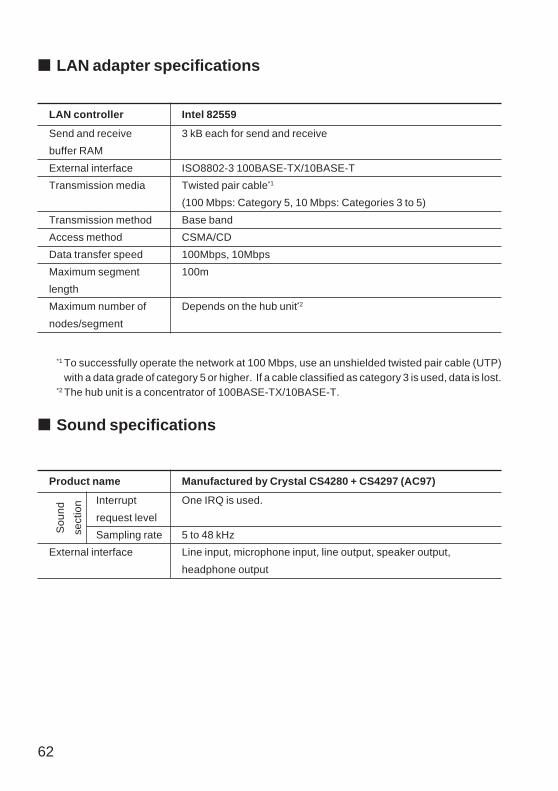
62
LAN controller
Send and receive
buffer RAM
External interface
Transmission media
Transmission method
Access method
Data transfer speed
Maximum segment
length
Maximum number of
nodes/segment
Intel 82559
3 kB each for send and receive
ISO8802-3 100BASE-TX/10BASE-T
Twisted pair cable*1
(100 Mbps: Category 5, 10 Mbps: Categories 3 to 5)
Base band
CSMA/CD
100Mbps, 10Mbps
100m
Depends on the hub unit*2
*1 To successfully operate the network at 100 Mbps, use an unshielded twisted pair cable (UTP)with a data grade of category 5 or higher. If a cable classified as category 3 is used, data is lost.
*2 The hub unit is a concentrator of 100BASE-TX/10BASE-T.
■ Sound specifications
■ LAN adapter specifications
Product name
Interrupt
request level
Sampling rate
External interface
Manufactured by Crystal CS4280 + CS4297 (AC97)
One IRQ is used.
5 to 48 kHz
Line input, microphone input, line output, speaker output,
headphone output
Sou
nd
sect
ion
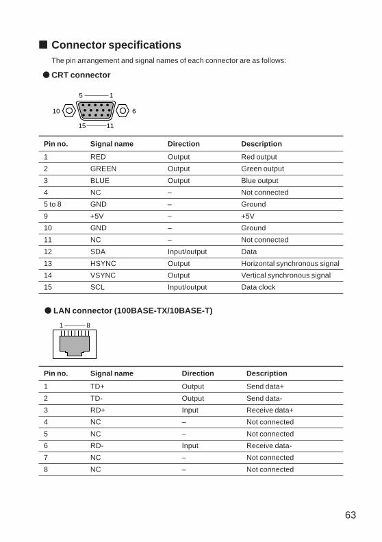
63
5 1
15
10 6
11
■ Connector specificationsThe pin arrangement and signal names of each connector are as follows:
● CRT connector
Pin no. Signal name Direction Description
1 TD+ Output Send data+
2 TD- Output Send data-
3 RD+ Input Receive data+
4 NC – Not connected
5 NC – Not connected
6 RD- Input Receive data-
7 NC – Not connected
8 NC – Not connected
Pin no. Signal name Direction Description
1 RED Output Red output
2 GREEN Output Green output
3 BLUE Output Blue output
4 NC – Not connected
5 to 8 GND – Ground
9 +5V – +5V
10 GND – Ground
11 NC – Not connected
12 SDA Input/output Data
13 HSYNC Output Horizontal synchronous signal
14 VSYNC Output Vertical synchronous signal
15 SCL Input/output Data clock
● LAN connector (100BASE-TX/10BASE-T)
1 8

64
Pin no. Signal name Direction Description
1 CD Input Carrier detection
2 RD Input Receive data
3 TD Output Send data
4 DTR Output Data terminal ready
5 GND – Ground
6 DSR Input Data set ready
7 RTS Output Send request
8 CTS Input Send enabled
9 RI Input Ring indication
Pin no. Signal name Direction Description
1 STROBE Input/output Strobe
2 DATA0 Input/output Data0
3 DATA1 Input/output Data1
4 DATA2 Input/output Data2
5 DATA3 Input/output Data3
6 DATA4 Input/output Data4
7 DATA5 Input/output Data5
8 DATA6 Input/output Data6
9 DATA7 Input/output Data7
10 ACK Input Acknowledge
11 BUSY Input Busy
12 PE Input Out of paper
13 SELECT Input Select
14 AUTOFD Output Automatic feed
15 ERROR Input Error
16 INIT Output Initialization
17 SLCTIN Output Select
18 to 25 GND – Ground
● Serial connector
13 1
25 14
1 5
6 9
● Parallel connector
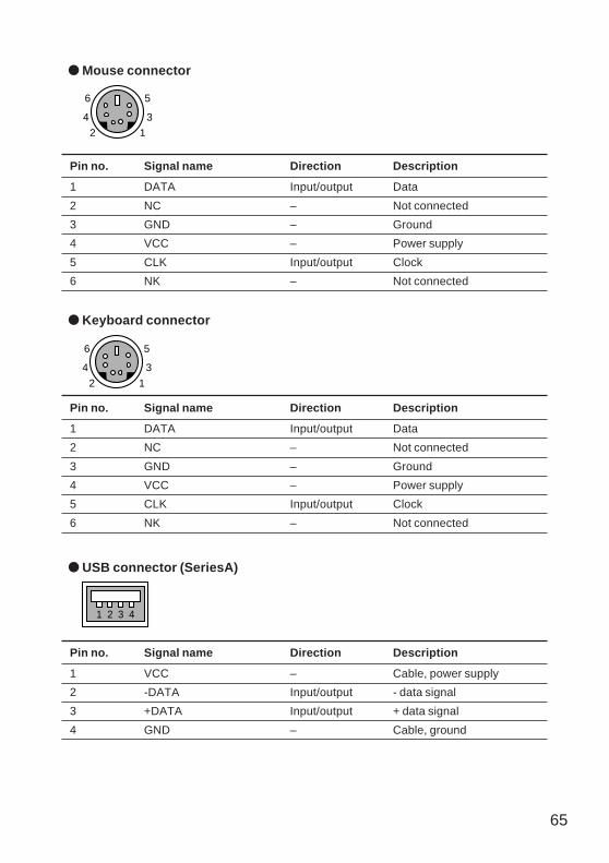
65
● USB connector (SeriesA)
Pin no. Signal name Direction Description
1 VCC – Cable, power supply
2 -DATA Input/output - data signal
3 +DATA Input/output + data signal
4 GND – Cable, ground
1 2 3 4
● Keyboard connector
Pin no. Signal name Direction Description
1 DATA Input/output Data
2 NC – Not connected
3 GND – Ground
4 VCC – Power supply
5 CLK Input/output Clock
6 NK – Not connected
6
4
2
5
3
1
Pin no. Signal name Direction Description
1 DATA Input/output Data
2 NC – Not connected
3 GND – Ground
4 VCC – Power supply
5 CLK Input/output Clock
6 NK – Not connected
6
4
2
5
3
1
● Mouse connector

66
How to clean the PC is explained as follows:
Electric shock
WARNING
● To prevent electric shock, before cleaning the PC, switch off the PC and allconnected units and unplug all power cords.
■ Cleaning the PC main unit- Wipe the PC main unit with a soft dry cloth. If necessary use a damp cloth but do not permit
moisture to come into contact with the PC main unit.- Periodically vacuum dust around ventilation holes with a vacuum cleaner to prevent the blocking
of ventilation holes by dust.
■ Cleaning the keyboardWipe the keyboard with a soft dry cloth.
■ Cleaning a CD-ROMWipe the CD-ROM disk, proceeding from the center to the rim, with a soft dry cloth. If necessaryuse a damp cloth followed by a soft dry cloth.
■ Cleaning the mouseUse a soft dry cloth. If the ball does not roll smoothly, remove the ball and clean. To clean the ballproceed as follows:
1 Remove the back cover of the mouse.
Turn the back cover of the mouse in the directionof the arrow to remove.
3 Cleaning Method

67
2 Remove the ball and clean with water.Reverse the mouse to remove the ball, thenclean the ball with water.
3 Clean the inside of the mouse.Wipe the inside of the mouse, the rollers, and theback cover with a damp cloth.
4 Attach the ball and the back cover.After drying the ball and the inside of the mouse,attach the ball and back cover.
■ Cleaning a floppy disk driveThe head (component for reading and writing data) of a floppy disk drive becomes dirty afterextended periods of use, thereby preventing efficient data reading or writing operations. Use thecleaning disk to clean the head every three months.
● For Windows 9X/NT model:
Mount the cleaning disk in a disk driveEnter a disk-access command such as "dir" at the command prompt of Windows.Example: Enter a command as follows and press the [Enter] key.
dir a:
Roller
68
■ Peripheral devices and cablesWhen peripheral devices or cables are connected to the PC, use Fujitsu-supplied devices andcables, as some non-Fujitsu devices and cables may not be connectable.
■ Note on using the displayThe vertical and horizontal lines displayed by a CAD application may appear different in widthdepending on the setting of the resolution of the display used. Adjust the setting correctly beforeusing.
■ Note on using an analog liquid crystal display• Connect a digital liquid crystal display to the PC and turn on the display power, then turn onthe
PC power.• If the digital liquid crystal display is connected to the PC or turned on after the PC power is
turned on, the display screen may remain blank.• The PC does not support to connect both of analog display and digital simultaneously. Use
either of them.• When digital display is used, set the resolution to up to 1024 X 768. The PC does not support
the resolution more than this value.
Display disturbed when the screen mode is changed
The screen display may experiance disturbance temporariry or horizontal lines may appear onthe screen when the screen display begins or ends or when the display mode changes, such aswhen Windows starts or ends or when the normal display mode is restored from the power savemode. These disturbances are not considered faults.
■ Digital display outputDigital display output is not compatible with a monitor exceeding XGA (1024X 768 pixels)resolution. Use an XGA or low-resolution monitor.
■ Replacing the displayIf the display is replaced with a different type of display (especially a liquid crystal dispaly), a displayerror such as blank screen may occur. If so, replace the display according to the followingprocedure:
4 Supplement

69
Windows 98/2000
1 Set the resolution to 640 x 480 (before replacement of the display).
2 Set the refresh rate to the "adapter default."
3 Terminate Windows and turn off the PC power, then replace the display.
If there is no screen display or no display at some resolutoion after the display is replaced withoutperforming the above setting, reinstall the display driver as follows:
1 Start Windows in Safe Mode.
2 Set the graphic adapter to "Standard Display Adapter (VGA)" or "Standard VGA" and restartWindows.
3 Reinstall the display driver.
Windows NT4.0 model
1 Turn off the power, then replace the display.
2 Start the PC with Windows NT Workstation Version 4.00 [VGA mode].
3 Set the resolution, the number of colors, and the refresh rate in accordance with the displayspecifications, then restart the PC.
■ Display and power save mode
Windows 98 model
When a display that does not support the power save mode is used, open to "Power ManagementProperties" and set "Never" for both "System Standby" and "Turn off Monitor Power."
Windows 2000 model
When a display that does not support the power save mode is used,open to "Power OptionsProperties" and set "Never" for both "System Standby" and "Turn off monotor".
■ About USB (Windows 98/2000)
USB stands for Universal Serisl Bus, which standardizes mouse. keyboard,
printer, modem, and speaker interfaces.
¤¤¤¤¤ Point• Some types of peripheral devices that support USB require special device drivers to be installed.• The OSs that support USB are Windows 98/2000.• When USB equipment is connected, Windows may not be terminated normally depending on
the type od USB equipment. If this is the case, disconnect the USB equipment and terminateWindows.
70
■ Wake up On LANWhen "Wake-up from LAN" under "Automatic wake-up" of the power save menu in the BIOS Setupis set to "Enable," the PC power can be tuned on via a LAN(WOL: Wake up On LAN). To use thisfunction , always turn on the PC power once after the power cable is connected. The functionmay not operate normally only if the power cable is connected.
■ Power Saving FunctionApplication operation becomes unstable if the power save function works during the followingtypes of operation. Disable the power save function for these types of operation.
• Playing back a Wave, MIDI, AVI, MPEG, or DAT file• Playing back a music CD• Recording by a sound recorder
■ LAN CableThe LAN built in this PC as standard equipment supports 100BASE-TX and 10BASE-T. Checkthe speed of the network to which the PC is to be connected and use the following type of cablein accordanc with the speed: Use a Fujitsu-supplied cable to minimize network trouble.
• 100BASE-TX: Unsealed twisted paired-cable(UTP) at category 5 or a higher data grade• 10BASE-T: UTP at category 3,4, or 5 data grade.
¤¤¤¤¤ Point• The Standard equipment LAN of this PC automatically adjusts to the network speed. If the
network speed changes, for example, because of hub unit replacement, use an adequatedata grade cable compatible with the speed.
■ LAN AdapterThis PC dows not allow that plural LAN adapters are used simultaneously by adding LAN adapterson Windows 98, Windows NT4.0 worstation and Windows 2000 Professional models. In order touse plural LAN adapters simultaneously, server OS such as Windows NT4.0 server and Windows2000 server is needed.
■ USB Keyboard (Windows 98 model)If "Enable shortcut key" is turned on in [Control Panel]-[Accessibility]-[Filter Function]-[Settings],the shortcut key function does not work and "Enabled filter key function" cannot be turned oneven if the "right shift" key is pressed for 8 or more seconds. Turn on the checkbox of "Enablefilter key function" using the mouse.

71
■ CD-ROM driveIf a CD-ROM cleaning disk sold separately is used for cleaning, the lens may not be clean. Do notuse a CD-ROM cleaning disk.
■ Intel ® processor serial numberEach Intel® Pentium® III processor contains a serial number that can be read electrically. Theprocessor serial number can be used for information management, resource management, andsecurity improvement on the web.
The user can read the processor serial number using software. The software read function canbe enabled or disabled using the BIOS Setup. The PC is shipped with this function disabled. Toenabled the function, set "Processor serial number" in the main menu of the BIOS Setup to"Enable."
■ Mouse with scroll function(wheel)When a USB keyboard and a mouse (PS/2) with the scroll function are used under Windows 98/2000, connect the mouse connector on the USB keyboard. If the mouse is connected to the mouseconnector on the PC, the mouse may not operate when Windows 98 is started in safe Mode.
72
Fujitsu PC (Asia) Pte Ltd
200 Pandan Loop
#05-03 Pantech 21
The Computer Centre
Singapore 128388
Tel: 65-776 0688
Fax: 65-776 0788
Fujitsu PC (Asia) Pte Ltd
(Malaysia Branch)
8th Floor Wisma Damansara
Jalan Semantan
50490 Kuala Lumpur
Malaysia
Tel: 603-253 3997
Fax: 603-253 4245
Website : www.fujitsu-pc-asia.com