Embed Size (px)
Citation preview
Designing of Simulation Model forPerformance Testing on
3G Radio Link Control Protocol
MallikaMallika UnhawiwawatUnhawiwawatCentre for Network Research
Department of Computer EngineeringFaculty of Engineering
Prince of Songkla University
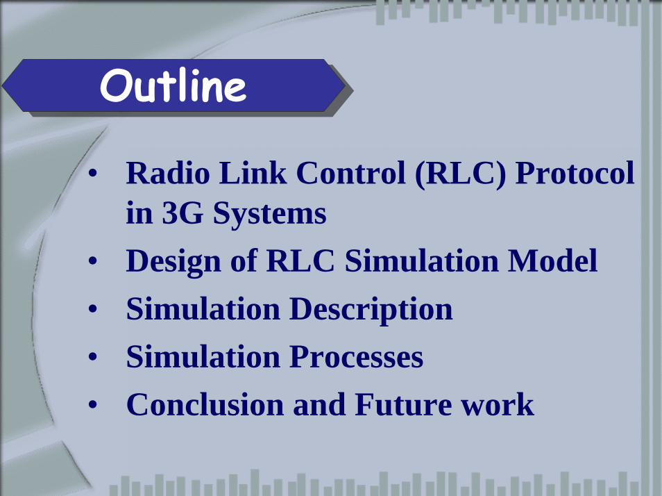
`Outline
• Radio Link Control (RLC) Protocol in 3G Systems
• Design of RLC Simulation Model• Simulation Description• Simulation Processes• Conclusion and Future work
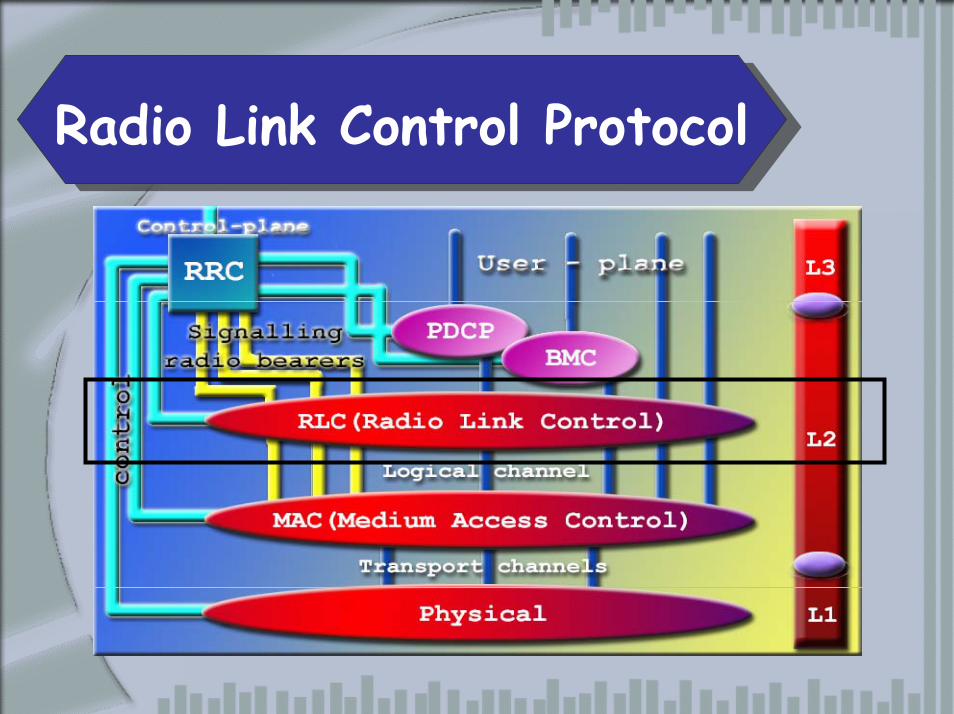
`Radio Link Control Protocol
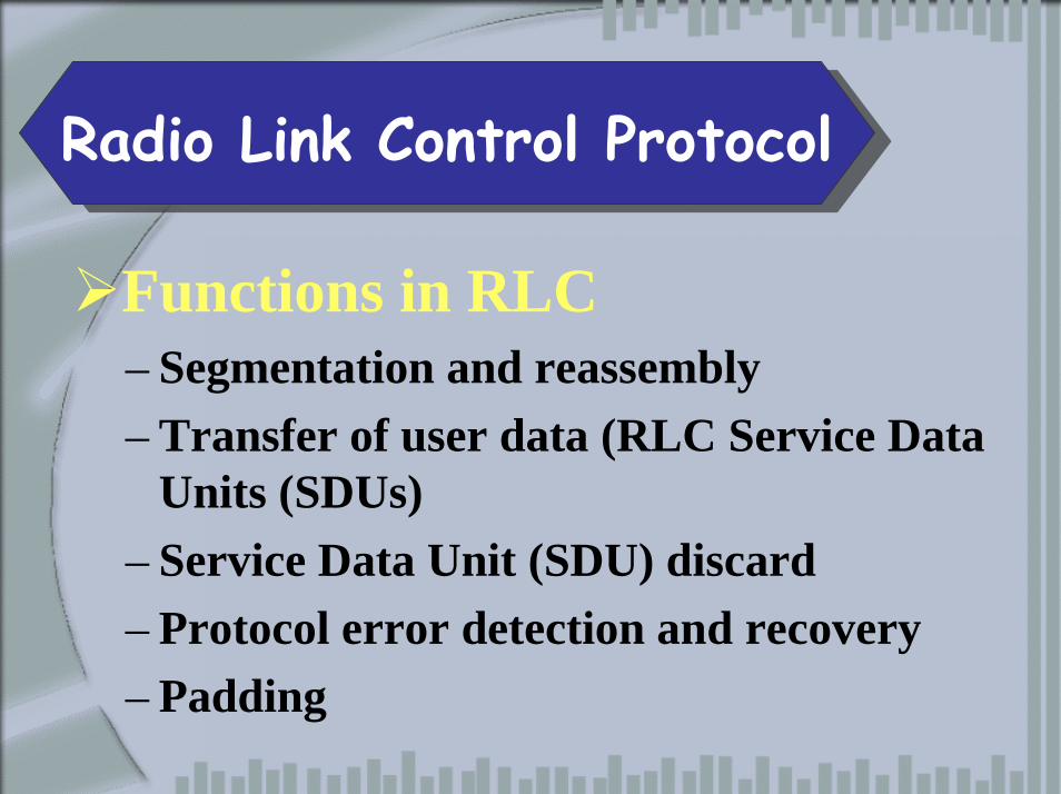
`Radio Link Control Protocol
Functions in RLC– Segmentation and reassembly– Transfer of user data (RLC Service Data
Units (SDUs)– Service Data Unit (SDU) discard– Protocol error detection and recovery– Padding
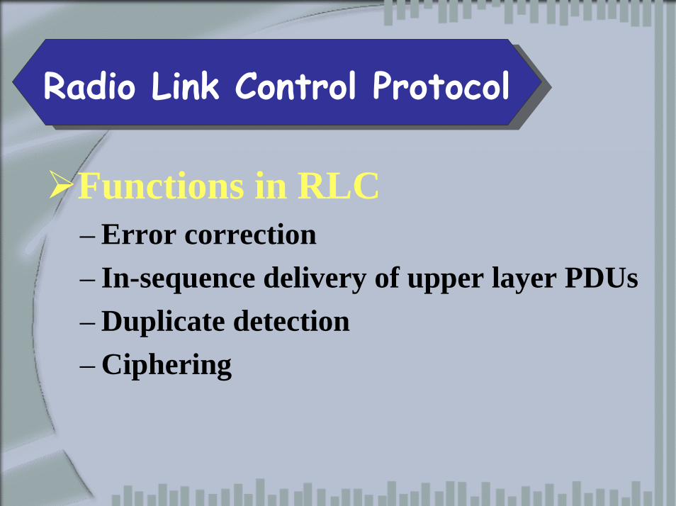
`Radio Link Control Protocol
Functions in RLC– Error correction– In-sequence delivery of upper layer PDUs– Duplicate detection– Ciphering
`Radio Link Control Protocol
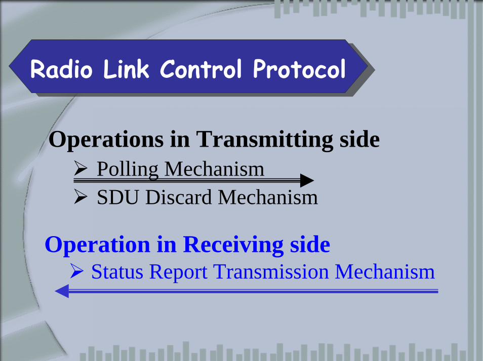
Operations in Transmitting sidePolling MechanismSDU Discard Mechanism
Operation in Receiving sideStatus Report Transmission Mechanism
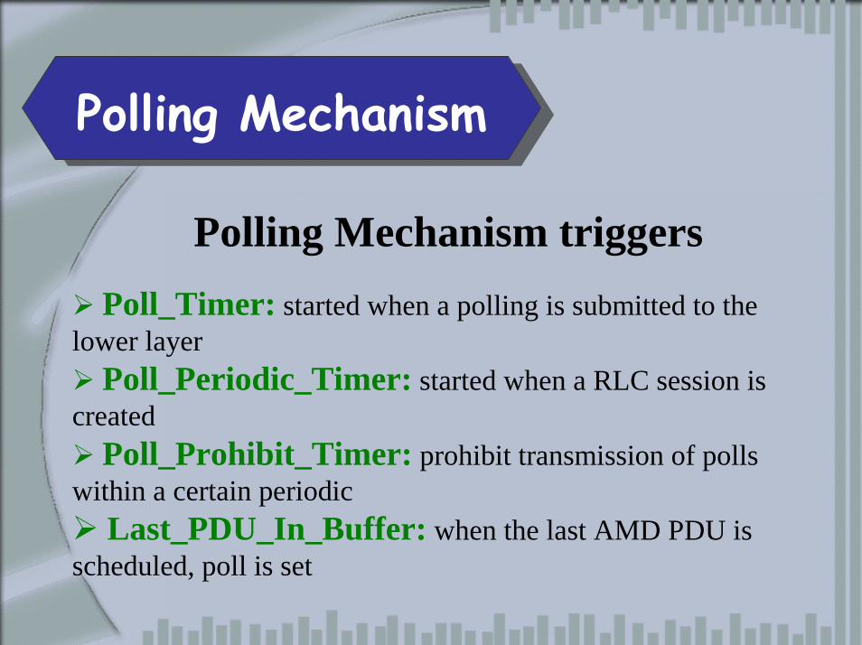
`Polling Mechanism
Polling Mechanism triggersPoll_Timer: started when a polling is submitted to the
lower layerPoll_Periodic_Timer: started when a RLC session is
createdPoll_Prohibit_Timer: prohibit transmission of polls
within a certain periodicLast_PDU_In_Buffer: when the last AMD PDU is
scheduled, poll is set
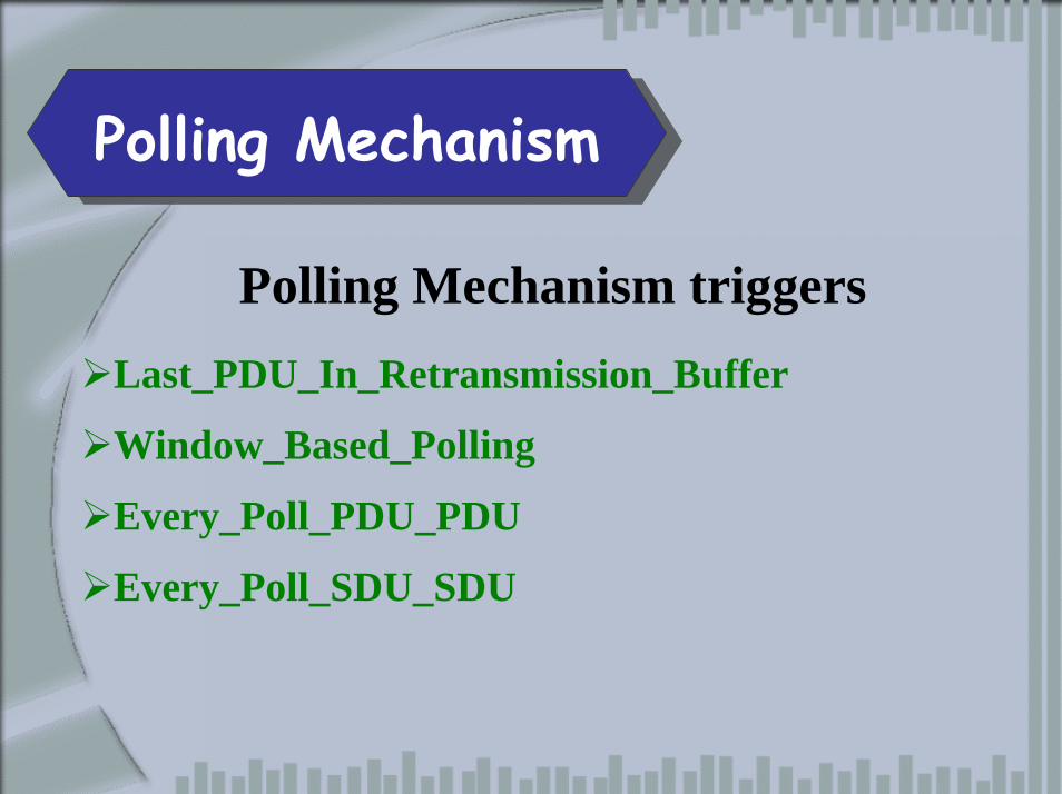
`Polling Mechanism
Polling Mechanism triggersLast_PDU_In_Retransmission_Buffer
Window_Based_Polling
Every_Poll_PDU_PDU
Every_Poll_SDU_SDU
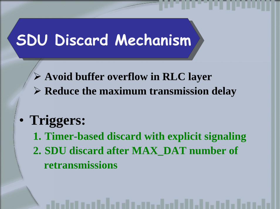
`SDU Discard Mechanism
Avoid buffer overflow in RLC layerReduce the maximum transmission delay
• Triggers:1. Timer-based discard with explicit signaling 2. SDU discard after MAX_DAT number of
retransmissions
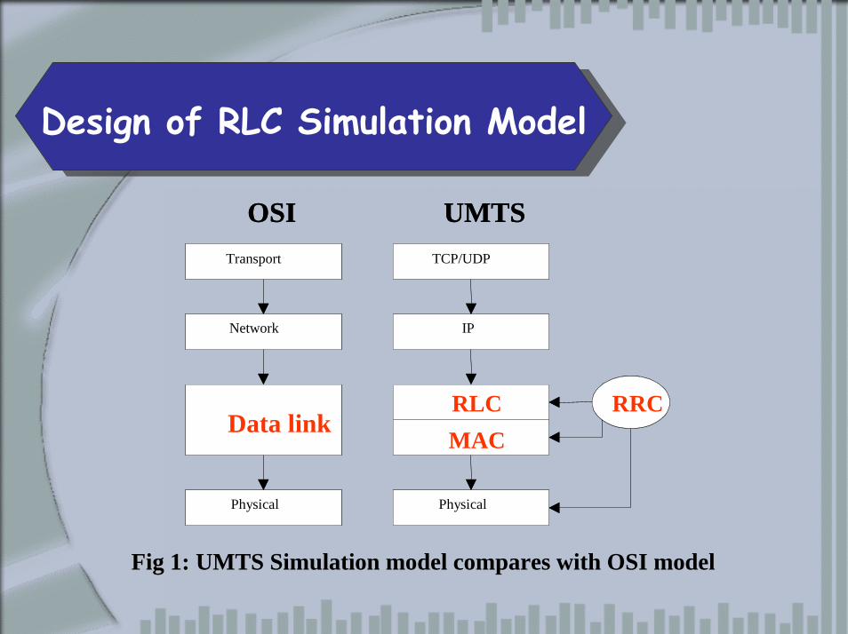
`Design of RLC Simulation Model
Transport
Network
Data link
Physical
TCP/UDP
IP
RLC
MAC
Physical
RRC
OSI UMTSTransport
Network
Data link
Physical
TCP/UDP
IP
RLCMAC
Physical
RRC
OSI UMTS
Fig Fig 11:: UMTS Simulation model compares with OSI model
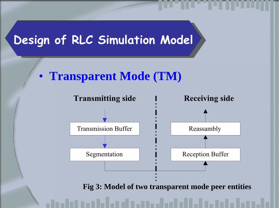
`Design of RLC Simulation Model
• Transparent Mode (TM)
Fig 3: Model of two transparent mode peer entities
Transmission Buffer
Segmentation
Reassambly
Reception Buffer
Transmitting side Receiving side
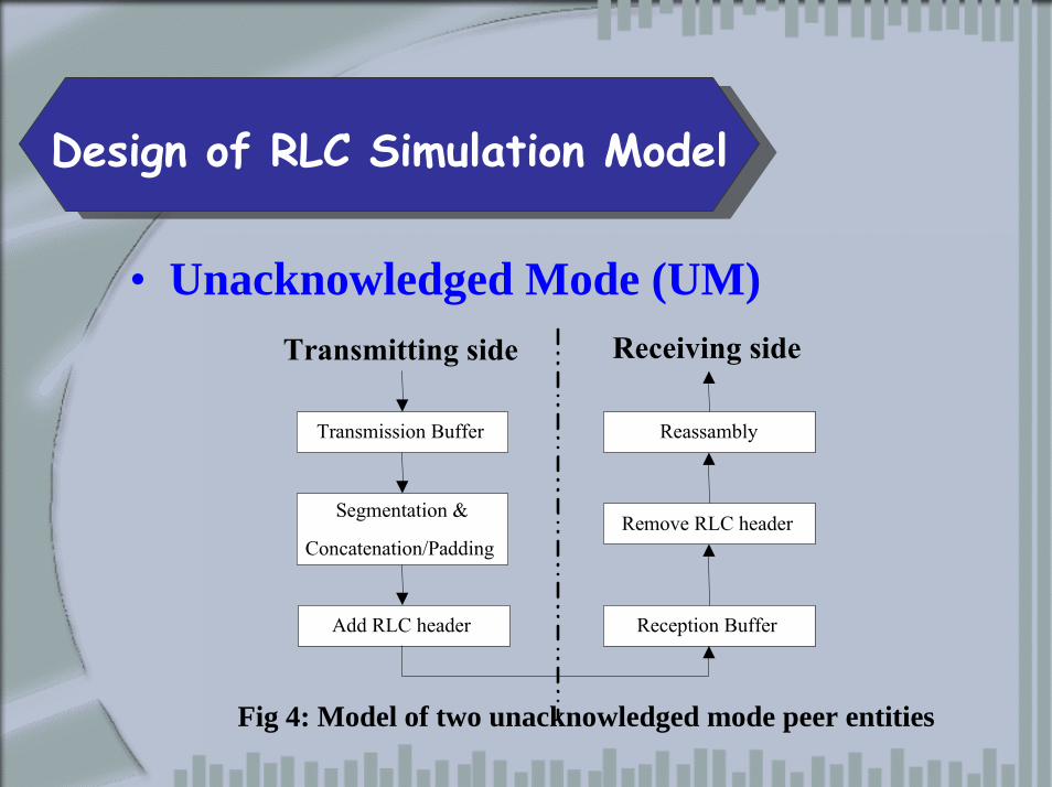
`Design of RLC Simulation Model
• Unacknowledged Mode (UM)
Fig 4: Model of two unacknowledged mode peer entities
Transmission Buffer
Segmentation &Concatenation/Padding
Reassambly
Remove RLC header
Add RLC header Reception Buffer
Transmitting side Receiving side
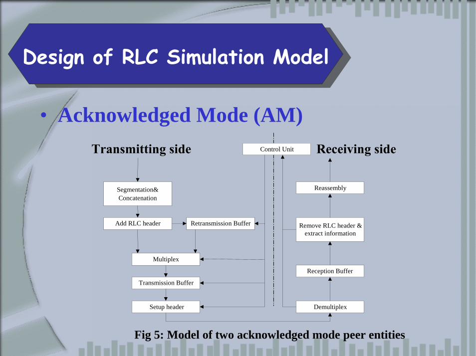
`Design of RLC Simulation Model
• Acknowledged Mode (AM)
Fig 5: Model of two acknowledged mode peer entities
Segmentation&Concatenation
Add RLC header Retransmission Buffer
Transmission Buffer
Setup header Demultiplex
Multiplex
Reception Buffer
Remove RLC header &extract information
Reassembly
Control UnitTransmitting side Receiving side
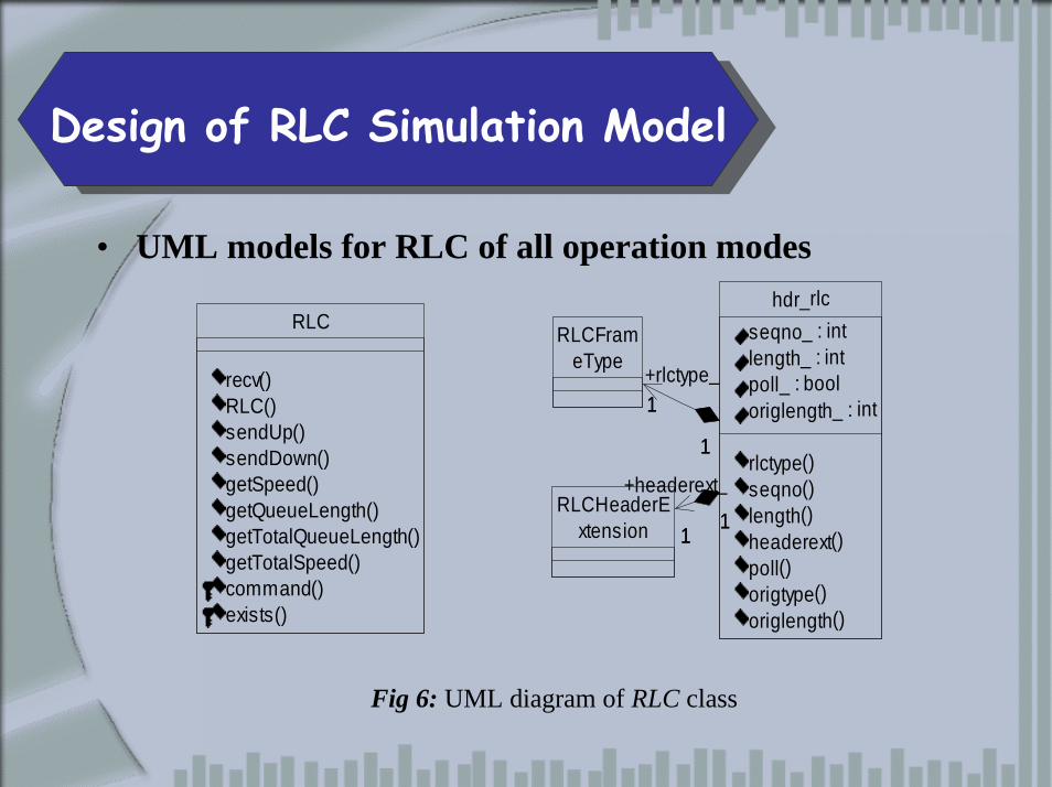
`Design of RLC Simulation Model
• UML models for RLC of all operation modes
RLC
recv()RLC()sendUp()sendDown()getSpeed()getQueueLength()getTotalQueueLength()getTotalSpeed()command()exists()
RLCFrameType
RLCHeaderExtension
hdr_rlcseqno_ : intlength_ : intpoll_ : booloriglength_ : int
rlctype()seqno()length()headerext()poll()origtype()origlength()
1
1
+rlctype_1
1
11
+headerext_
11
Fig 6: UML diagram of RLC class
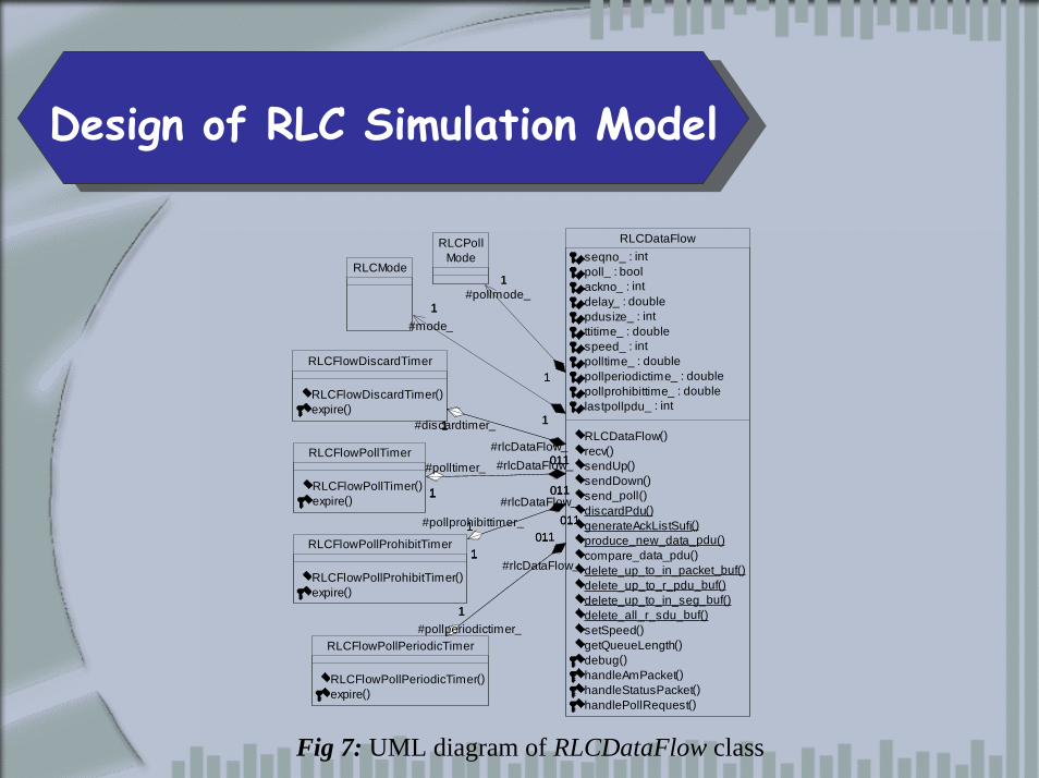
`Design of RLC Simulation Model
RLCMode
RLCFlowDiscardTimer
RLCFlowDiscardTimer()expire()
RLCFlowPollTimer
RLCFlowPollTimer()expire()
RLCFlowPollProhibitTimer
RLCFlowPollProhibitTimer()expire()
RLCFlowPollPeriodicTimer
RLCFlowPollPeriodicTimer()expire()
RLCPollMode
RLCDataFlowseqno_ : intpoll_ : boolackno_ : intdelay_ : doublepdusize_ : intttitime_ : doublespeed_ : intpolltime_ : doublepollperiodictime_ : doublepollprohibittime_ : doublelastpollpdu_ : int
RLCDataFlow()recv()sendUp()sendDown()send_poll()discardPdu()generateAckListSufi()produce_new_data_pdu()compare_data_pdu()delete_up_to_in_packet_buf()delete_up_to_r_pdu_buf()delete_up_to_in_seg_buf()delete_all_r_sdu_buf()setSpeed()getQueueLength()debug()handleAmPacket()handleStatusPacket()handlePollRequest()
0..1
1
#rlcDataFlow_
0..11
#rlcDataFlow_
0..1
1
#rlcDataFlow_
0..11
#rlcDataFlow_
1
1
#mode_
1
1
#discardtimer_
1 1
#polltimer_
1
1#pollprohibittimer_
1
1
#pollperiodictimer_
1
1
#pollmode_
0..1
1
0..11
0..1
10..1
1
1
11
1
1 1
1
1
1
1
1
1
Fig 7: UML diagram of RLCDataFlow class
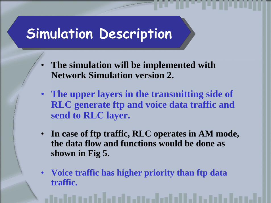
4. `Simulation Description
• The simulation will be implemented with Network Simulation version 2.
• The upper layers in the transmitting side of RLC generate ftp and voice data traffic and send to RLC layer.
• In case of ftp traffic, RLC operates in AM mode, the data flow and functions would be done as shown in Fig 5.
• Voice traffic has higher priority than ftp data traffic.
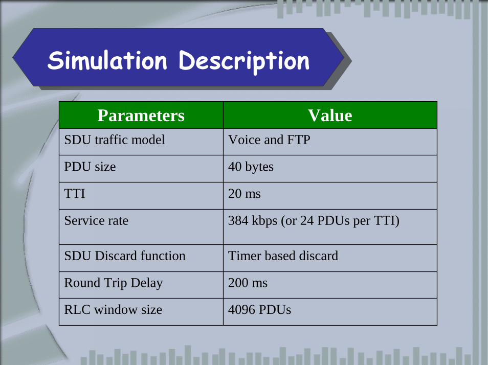
`Simulation Description
Parameters ValueSDU traffic model Voice and FTP
PDU size 40 bytes
TTI 20 ms
Service rate 384 kbps (or 24 PDUs per TTI)
SDU Discard function Timer based discard
Round Trip Delay 200 ms
RLC window size 4096 PDUs
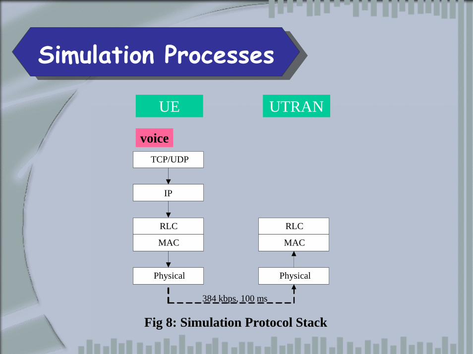
`Simulation Processes
UE UTRAN
voiceTCP/UDP
IP
RLC
MAC
Physical
RLC
MAC
Physical
384 kbps, 100 ms
Fig 8: Simulation Protocol Stack
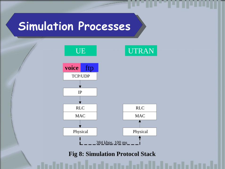
`Simulation Processes
UE UTRAN
voice ftpTCP/UDP
IP
RLC
MAC
Physical
RLC
MAC
Physical
384 kbps, 100 ms
Fig 8: Simulation Protocol Stack
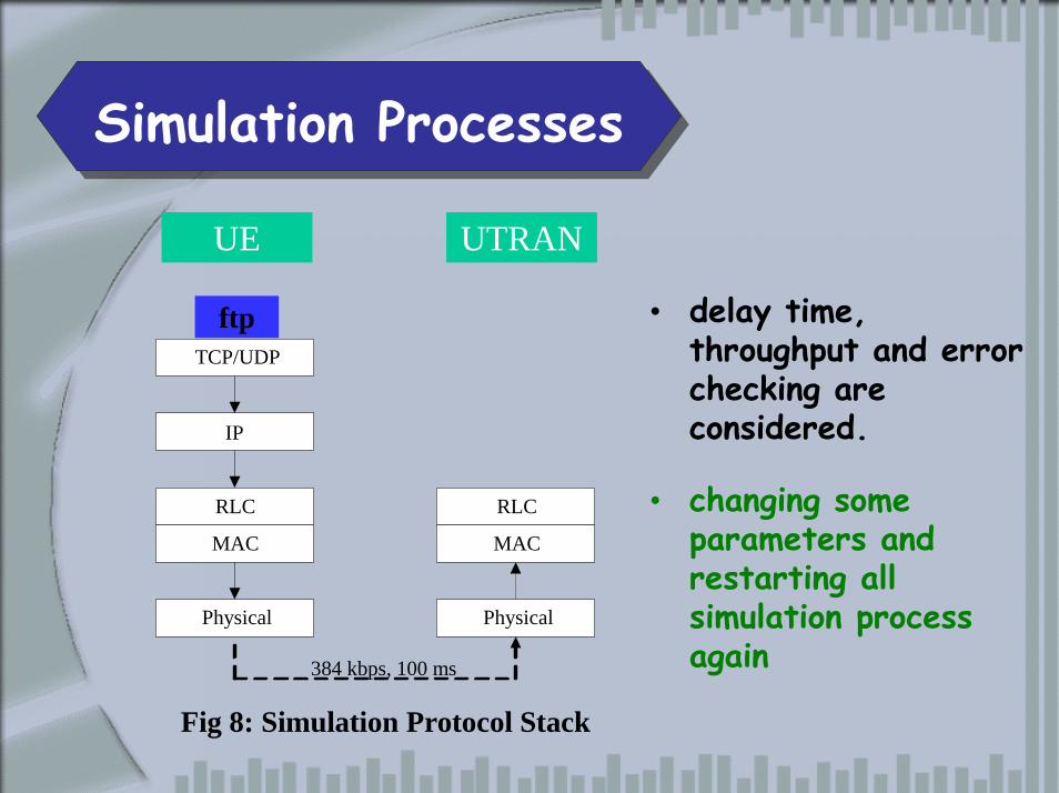
`Simulation Processes
TCP/UDP
IP
RLC
MAC
Physical
RLC
MAC
Physical
384 kbps, 100 ms
UE UTRAN
ftp • delay time, throughput and error checking are considered.
• changing some parameters and restarting all simulation process again
Fig 8: Simulation Protocol Stack
`Conclusion and Future works
• We present the overview and designed of RLC simulation model for performance testing and show in UML diagrams.
• The simulation model will be completely implemented in NS2 and used to analyze the RLC performance.
Comment and QuestionsComment and Questions
Thank you Thank you