Embed Size (px)
Citation preview
1
DESIGNING OF AN INTELLIGENT TEMPERATURE-CUM-HUMIDITY
MONITORING DEVICE
A THESIS SUBMITTED IN PARTIAL FULFILLMENT
OF THE REQUIREMENTS FOR THE DEGREE OF
BACHELOR OF TECHNOLOGY
IN
BIO-MEDICAL ENGINEERING
SUBMITTED BY
RIPUNJAY CHACHAN
110BM0627
UNDER THE GUIDANCE OF
Dr. KUNAL PAL
DEPARTMENT OF BIOTECHNOLOGY AND MEDICAL ENGINEEIRNG
NATIONAL INSTITUTE OF TECHNOLOGY
ROURKELA-769008
2
DEPARTMENT OF BIOTECHNOLOGY & MEDICAL ENGINEERING,
NATIONAL INSTITUTE OF TECHNOLOGY-ROURKELA
Dated: 1st DECEMBER, 2014
CERTIFICATE
This is to certify that the thesis entitled “DESIGNING OF AN INTELLIGENT
TEMPERATURE-CUM-HUMIDITY MONITORING DEVICE” submitted by Mr.
Ripunjay Chachan in partial fulfillment for the requirements for the award of Bachelor of
Technology Degree in Biotechnology at National Institute of Technology, Rourkela is an authentic
work carried out by him under the supervision of the undersigned.
To the best of my knowledge, the matter embodied in the thesis has not been submitted to any
other University / Institute for the award of any Degree or Diploma.
(Dr. KUNAL PAL) Assistant Professor
3
ACKNOWLEDGEMENT
I would like to express my deep sense of gratitude and respect to our supervisor, Dr. Kunal Pal,
Assistant Professor, Department of Biotechnology and medical Engineering, National Institute of
Technology Rourkela for his excellent guidance, suggestions and constructive criticism. He has
been very kind, supportive and patient to me while suggesting the outlines of the project and has
also been very helpful in the successful completion of the same. I thank him for his overall support.
Last but not the least I would like to extend my heartfelt gratitude to the PhD. and M.Tech scholars,
Department of Biotechnology and Medical Engineering, National Institute of Technology,
Rourkela for their support and guidance. Their helping nature and suggestion has helped me to
complete this present work.
I am really thankful to National Institute of Technology, Rourkela, for permitting me to utilize the
facilities in its laboratories for the smooth execution of my experiment.
I extend my warm gratitude to my friends, Mr. Dablu Ranjan and Mr. Krishna Kumar, for their
constant motivation and support throughout the course of my B.Tech research. Finally, I would
like to thank my seniors, juniors and my fellow students who enthusiastically supported me by
providing the necessary data.
Date: Ripunjay chachan
4
CONTENTS LIST OF TABLES ....................................................................................................................5
LIST OF FIGURES ..................................................................................................................6
ABSTRACT...............................................................................................................................7
1. INTRODUCTION ..............................................................................................................9
2. LITERATURE REVIEW ................................................................................................ 11
3. MATERIALS AND METHODS ..................................................................................... 13
3.1. MATERIALS ............................................................................................................... 13
3.2. METHODS ................................................................................................................... 17
4. RESULT AND DISCUSSIONS...................................................................................... 20
5. CONCLUSION ................................................................................................................ 27
REFERENCES ........................................................................................................................ 28
5
LIST OF TABLES
Table 1: Specifications of Arduino UNO ................................................................................ 13
Table 2: Specifications of DHT11 Sensor ............................................................................... 15
6
LIST OF FIGURES
Figure 1: Arduino UNO .......................................................................................................... 13
Figure 2: Arduino GSM Shield (a) front side (b) back side ................................................... 14
Figure 3: DHT11 Sensor ......................................................................................................... 15
Figure 4: X-Bee ....................................................................................................................... 16
Figure 5: X-Bee Shield ............................................................................................................ 16
Figure 7: 9V Duracell Battery ................................................................................................ 17
Figure 8: Flow chart of device ................................................................................................ 17
Figure 9: GUI interface ........................................................................................................... 21
Figure 10: Flow of functionality of the device ........................................................................ 22
Figure 11: Schematic of case 1(a) ........................................................................................... 23
Figure 12: Schematic of case 1(b) ........................................................................................... 24
Figure 13: Schematic of case 2 ................................................................................................ 25
7
ABSTRACT
The present study that is described in designing of a temperature-cum-humidity monitoring
system. This designed system can be used for alarming the user via short message sending
(SMS) in the wake of a criticality of an event; which is predefined by the user. The system
can also be used to log data in a remote computer. There is an urgent need for this type of
devices for different industries that include agricultural biomedical and pharmaceutical
industries. In these industries mentioned above there is a need for controlled environmental
conditions which mainly include temperature and humidity. Any deviation or change in the
environmental controlled conditions can lead to financial loses in agricultural and
pharmaceutical industries and can be life threating to the users of biomedical industries.
By the alerting the user in immediately this loses can be prevented. The controlled
environment can help in preventing any kind of loss by immediate alarming.

8
CHAPTER 1
INTRODUCTION
9
1. INTRODUCTION
The major industries in India include biomedical, agricultural and pharmaceutical which forms
backbone of countries economy. The continuous monitoring of temperature and humidity is a
major criteria in all the above mentioned industries[1]. The controlled environment forms a
foremost criteria in all of the above industries. Any kind of deviation in the environmental
conditions or the preset parameters can cost heavy financial losses due to alterations in productivity
in the pharmaceutical and agricultural industries. A precise monitoring of humidity and
temperature is required in biomedical industry sue to the screening of drugs and use of various cell
culture methods. While providing life support in healthcare sectors the environment controlled
conditions is required. The variations in environment i.e. temperature and humidity of patients
could be life threatening. Taking the above factors in consideration the current paper was designed
to develop intelligent temperature-cum-humidity monitoring[2]. The technological advancements
in various field including instrumentation is kept in mind and care was taken to utilize it. This
improves the functionality of the device proposed. Wireless system using ZigBee was
implemented so as to reduce the complexity of the device during handling. The ZigBee module
which consists of a transmitter and receiver was utilized to record data to the monitoring station
from the sensor[3]. Additionally a GSM module was used to alarm the user in the wake of a critical
event.
.

10
CHAPTER 2
LITERATURE REVIEW
11
2. LITERATURE REVIEW
A large amount of research works are being carried out in various institutions across the world to
provide a better managed, efficient and cost effective way for simultaneous measurement of
temperature and humidity. Temperature and Relative humidity both are very important parameters
of the environment in many industrial such as food, medicine, papermaking, textile,
meteorological, semiconductor, services etc. In recent years, optical fiber sensors have attracted
more and more attentions in sensing and measurement areas due to their many advantage over
their conventional electronic counterparts. Similar works in this particular area make use of the
Short Message Service (SMS) facility so as to alert the user as seen in the paper[4].The
temperature-humidity sensor could be also used in tissue culture lab use this particular mechanism
and use a GSM module to send a message which displays the present status of the temperature and
humidity and displays the message “Tissue Culture lab parameters exceeded”. But majority of
times such an alerting message could easily go unnoticed, the user or the person in charge is
sleeping in case if the intended person in sleeping.so it is better to log the data in a remote computer
in case of such an event so that he can keep an track of the data. Another work in [5] use the
alarming system for the Attending staff. This temperature and humidity measurement sensor can
fail if the user of the in charge is Away for the situation where the emergency is taking place[6].
A temperature and humidity rise and alarm following it would be unnoticed.so a robust device
combining an alerting and data logging system is needed to avoid this kind of situation. The paper
[7] deals with sending the values of temperature of the environment the sensor is exposed to, by
SMS for the user or the person in charge. Also, by creating microcontroller database, this design
described in the paper can be used as a modification for alerting the user by giving an “ALERT
SMS” when the temperature have a deviation from a critical value preset by the user[8]. The
system of server guard maintenance mechanism presented in this current paper is totally different
as it doesn’t take into consider any software which has to be run in personal or any computer[9].
The final product doesn’t take into consideration any high power consumption devices like laptop
or personal computer. The response of our design when the temperature or humidity is out of range
as defined by the user or the critical value preset by the user is better and more advanced as we
have the provision for data logging as well as to alert the user in case of an alarming event.
12
CHAPTER 3
MATERIALS AND METHODS
13
Figure 1: Arduino UNO
3. MATERIALS AND METHODS
3.1. MATERIALS
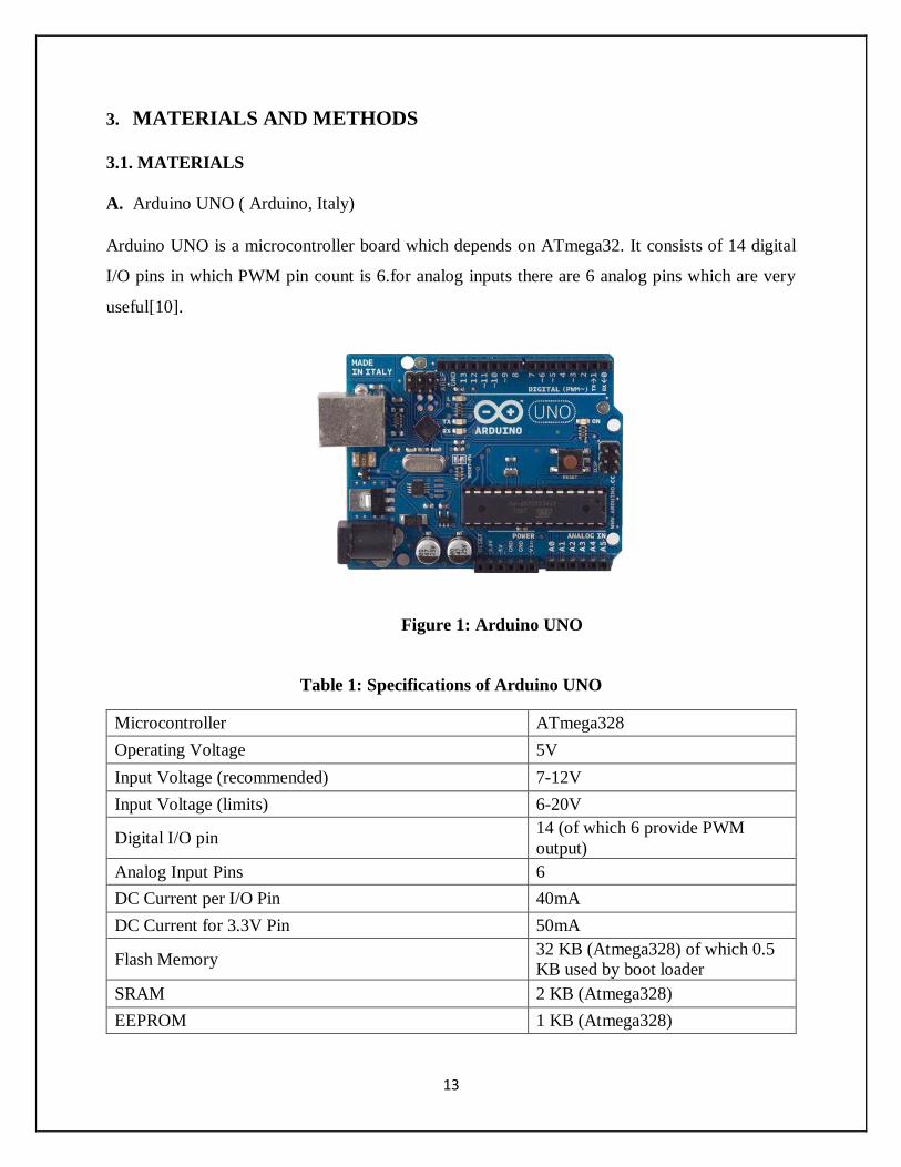
A. Arduino UNO ( Arduino, Italy)
Arduino UNO is a microcontroller board which depends on ATmega32. It consists of 14 digital
I/O pins in which PWM pin count is 6.for analog inputs there are 6 analog pins which are very
useful[10].
Table 1: Specifications of Arduino UNO
Microcontroller ATmega328
Operating Voltage 5V
Input Voltage (recommended) 7-12V
Input Voltage (limits) 6-20V
Digital I/O pin 14 (of which 6 provide PWM
output)
Analog Input Pins 6
DC Current per I/O Pin 40mA
DC Current for 3.3V Pin 50mA
Flash Memory 32 KB (Atmega328) of which 0.5
KB used by boot loader
SRAM 2 KB (Atmega328)
EEPROM 1 KB (Atmega328)
14
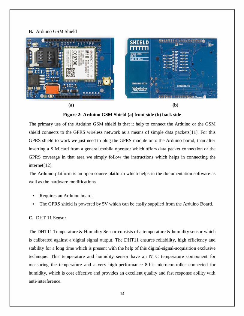
B. Arduino GSM Shield
(a) (b)
Figure 2: Arduino GSM Shield (a) front side (b) back side
The primary use of the Arduino GSM shield is that it help to connect the Arduino or the GSM
shield connects to the GPRS wireless network as a means of simple data packets[11]. For this
GPRS shield to work we just need to plug the GPRS module onto the Arduino borad, than after
inserting a SIM card from a general mobile operator which offers data packet connection or the
GPRS coverage in that area we simply follow the instructions which helps in connecting the
internet[12].
The Arduino platform is an open source platform which helps in the documentation software as
well as the hardware modifications.
Requires an Arduino board.
The GPRS shield is powered by 5V which can be easily supplied from the Arduino Board.
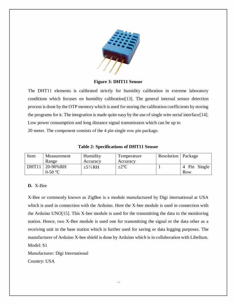
C. DHT 11 Sensor
The DHT11 Temperature & Humidity Sensor consists of a temperature & humidity sensor which
is calibrated against a digital signal output. The DHT11 ensures reliability, high efficiency and
stability for a long time which is present with the help of this digital-signal-acquisition exclusive
technique. This temperature and humidity sensor have an NTC temperature component for
measuring the temperature and a very high-performance 8-bit microcontroller connected for
humidity, which is cost effective and provides an excellent quality and fast response ability with
anti-interference.
15
Figure 3: DHT11 Sensor
The DHT11 elements is calibrated strictly for humidity calibration in extreme laboratory
conditions which focuses on humidity calibration[13]. The general internal sensor detection
process is done by the OTP memory which is used for storing the calibration coefficients by storing
the programs for it. The integration is made quite easy by the use of single wire serial interface[14].
Low power consumption and long distance signal transmission which can be up to
20 meter. The component consists of the 4 pin single row pin package.
Table 2: Specifications of DHT11 Sensor
Item Measurement
Range
Humidity
Accuracy
Temperature
Accuracy
Resolution Package
DHT11 20-90%RH
0-50 ℃ ±5%RH ±2℃ 1 4 Pin Single
Row
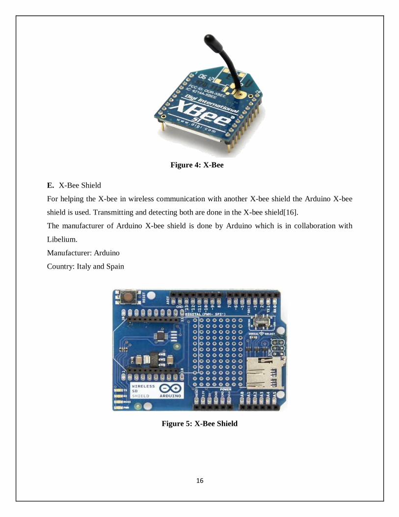
D. X-Bee
X-Bee or commonly known as ZigBee is a module manufactured by Digi international at USA
which is used in connection with the Arduino. Here the X-bee module is used in connection with
the Arduino UNO[15]. This X-bee module is used for the transmitting the data to the monitoring
station. Hence, two X-Bee module is used one for transmitting the signal or the data other as a
receiving unit in the base station which is further used for saving or data logging purposes. The
manufacturer of Arduino X-bee shield is done by Arduino which is in collaboration with Libelium.
Model: S1
Manufacturer: Digi International
Country: USA
16
Figure 4: X-Bee
E. X-Bee Shield
For helping the X-bee in wireless communication with another X-bee shield the Arduino X-bee
shield is used. Transmitting and detecting both are done in the X-bee shield[16].
The manufacturer of Arduino X-bee shield is done by Arduino which is in collaboration with
Libelium.
Manufacturer: Arduino
Country: Italy and Spain
Figure 5: X-Bee Shield
17
Figure 6: 9V Duracell Battery
F. Battery
A rechargeable typical 9V battery was used to power the device.
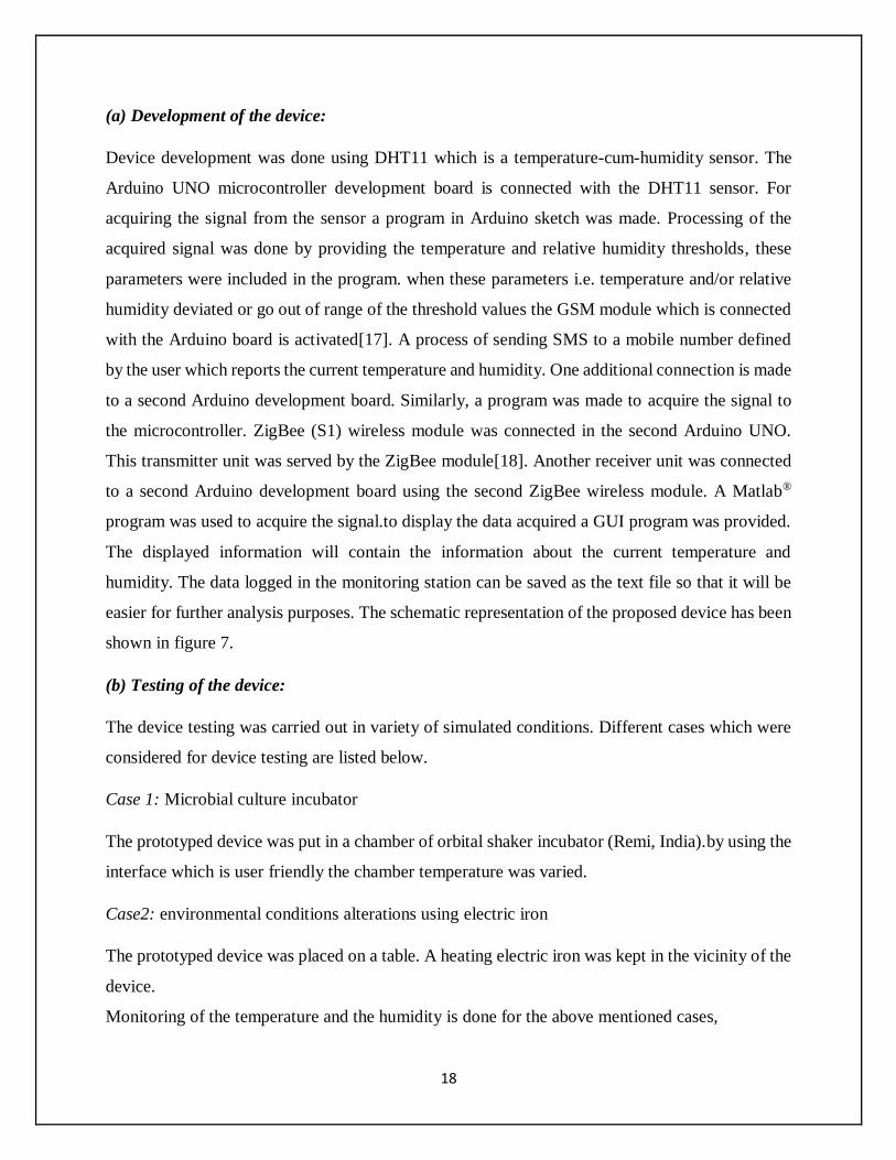
3.2.METHODS
Figure 7: Flow chart of device
DHT 11 SENSOR
ARDUINO ARDUINO
Sim 900 GSM/GPRS SHIELD ZIGBEE (S1)
TRANSMITTER SHIELD
ZIGBEE (S1)
RECIEVER SHIELD
ARDUINO
9V BATTERY
18
(a) Development of the device:
Device development was done using DHT11 which is a temperature-cum-humidity sensor. The
Arduino UNO microcontroller development board is connected with the DHT11 sensor. For
acquiring the signal from the sensor a program in Arduino sketch was made. Processing of the
acquired signal was done by providing the temperature and relative humidity thresholds, these
parameters were included in the program. when these parameters i.e. temperature and/or relative
humidity deviated or go out of range of the threshold values the GSM module which is connected
with the Arduino board is activated[17]. A process of sending SMS to a mobile number defined
by the user which reports the current temperature and humidity. One additional connection is made
to a second Arduino development board. Similarly, a program was made to acquire the signal to
the microcontroller. ZigBee (S1) wireless module was connected in the second Arduino UNO.
This transmitter unit was served by the ZigBee module[18]. Another receiver unit was connected
to a second Arduino development board using the second ZigBee wireless module. A Matlab®
program was used to acquire the signal.to display the data acquired a GUI program was provided.
The displayed information will contain the information about the current temperature and
humidity. The data logged in the monitoring station can be saved as the text file so that it will be
easier for further analysis purposes. The schematic representation of the proposed device has been
shown in figure 7.
(b) Testing of the device:
The device testing was carried out in variety of simulated conditions. Different cases which were
considered for device testing are listed below.
Case 1: Microbial culture incubator
The prototyped device was put in a chamber of orbital shaker incubator (Remi, India).by using the
interface which is user friendly the chamber temperature was varied.
Case2: environmental conditions alterations using electric iron
The prototyped device was placed on a table. A heating electric iron was kept in the vicinity of the
device.
Monitoring of the temperature and the humidity is done for the above mentioned cases,
19
CHAPTER 4
RESULTS AND DISCUSSIONS
20
4. RESULT AND DISCUSSIONS
To build an intelligent temperature-cum-humidity sensor the temperature and the humidity
measuring sensor (DHT11) sensor was used. The Arduino development board was used acquired
the signal provided by the DHT11 sensor[19]. If there is any deviation in the neighboring
environment of the sensor the measured parameters being temperature and humidity. If the preset
range parameters gets out the GSM module is activated for sending messages. A mobile number
is already predefined in the Arduino program. The GSM module send this messages to the mobile
number mentioned in the program as soon as the GSM module is activated[20]. The next message
will be send only after 10 minutes. Thus delay of 10 minutes is provided to give the user time to
take care of the problem to bring back the normal environmental conditions fixed for that particular
environment.so that the continuous messaging can be stopped. After 10 minutes another message
will be send if the problem or the environmental conditions are not brought back. This process can
be stopped by switching off the device or when the environmental temperature and humidity were
restored.
A ZigBee (S1) transmitter connected with the Arduino development board is used to
simultaneously send the signal that is acquired from the sensor[18]. The signal transmitted by the
ZigBee module was send to the computer or the monitoring station where the data could be saved
or graph plotting as text file can be done using the GUI program made in the Matlab®.
The Matlab®. GUI interface for the development of the device has been shown in the figure 9.
21
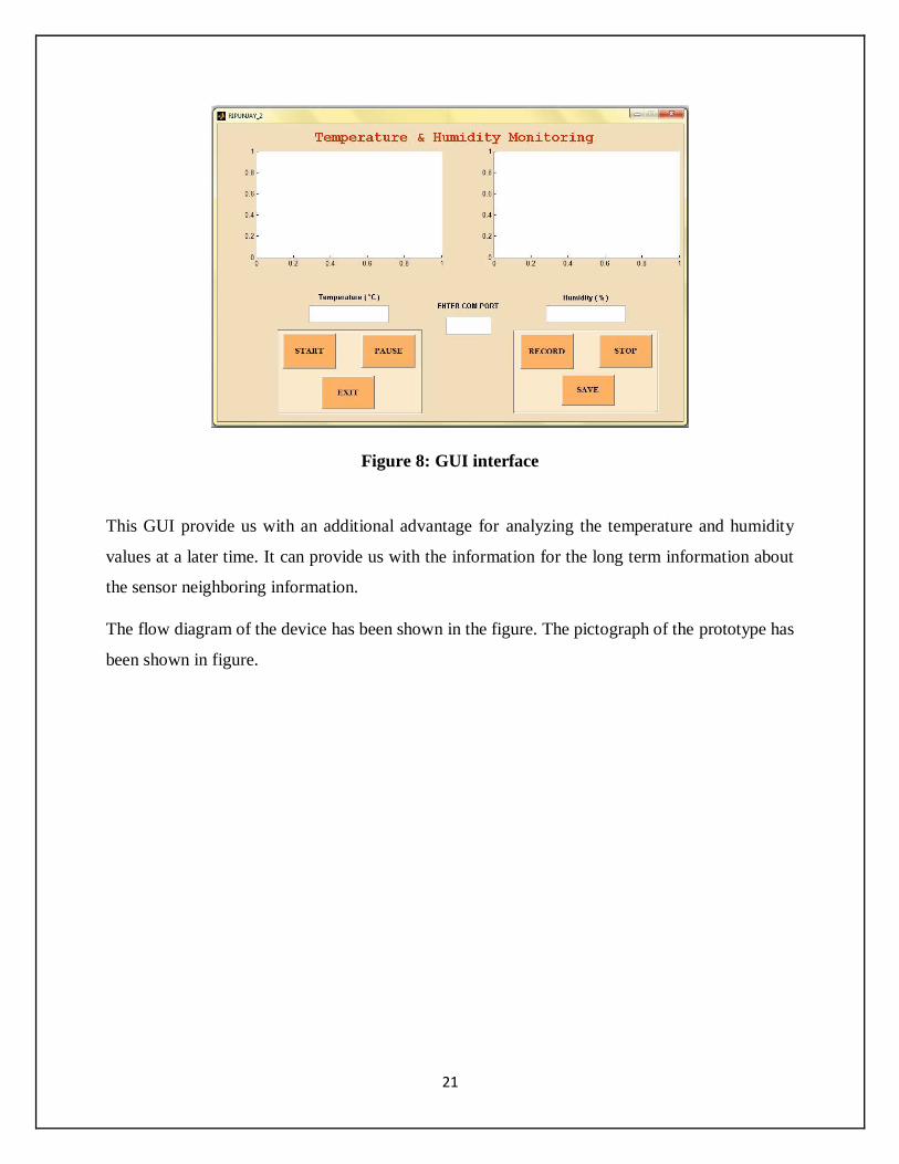
Figure 8: GUI interface
This GUI provide us with an additional advantage for analyzing the temperature and humidity
values at a later time. It can provide us with the information for the long term information about
the sensor neighboring information.
The flow diagram of the device has been shown in the figure. The pictograph of the prototype has
been shown in figure.
22
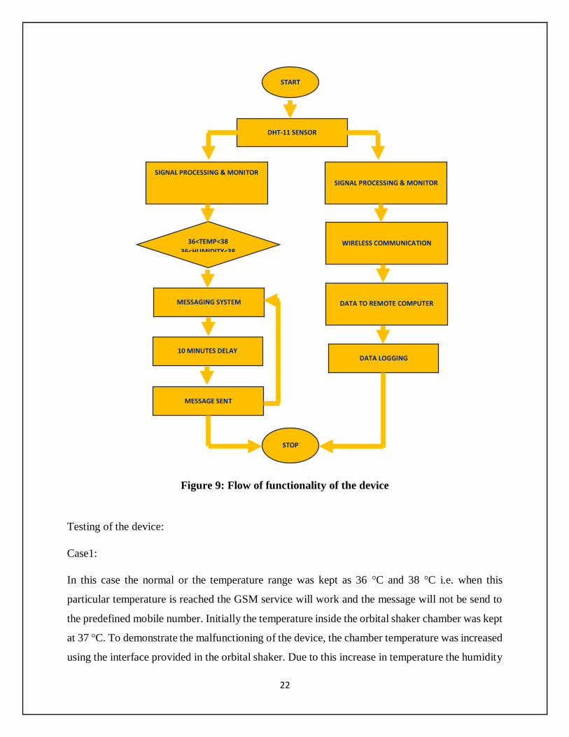
Figure 9: Flow of functionality of the device
Testing of the device:
Case1:
In this case the normal or the temperature range was kept as 36 °C and 38 °C i.e. when this
particular temperature is reached the GSM service will work and the message will not be send to
the predefined mobile number. Initially the temperature inside the orbital shaker chamber was kept
at 37 °C. To demonstrate the malfunctioning of the device, the chamber temperature was increased
using the interface provided in the orbital shaker. Due to this increase in temperature the humidity
START
DHT-11 SENSOR
DATA LOGGING
DATA TO REMOTE COMPUTER
WIRELESS COMMUNICATION
SIGNAL PROCESSING & MONITOR
SIGNAL PROCESSING & MONITOR
36<TEMP<38
36<HUMIDITY<38
MESSAGING SYSTEM
MESSAGE SENT
STOP
10 MINUTES DELAY
23
decrease as they are related. The datas provided by the DHT11 sensor i.e. increase in the
temperature and the decrease in humidity, the GSM module is activated. Using the communication
protocol followed by the ZigBee continuous transmission of data is possible.
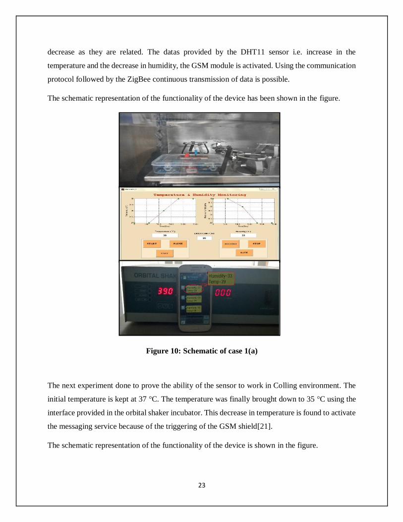
The schematic representation of the functionality of the device has been shown in the figure.
Figure 10: Schematic of case 1(a)
The next experiment done to prove the ability of the sensor to work in Colling environment. The
initial temperature is kept at 37 °C. The temperature was finally brought down to 35 °C using the
interface provided in the orbital shaker incubator. This decrease in temperature is found to activate
the messaging service because of the triggering of the GSM shield[21].
The schematic representation of the functionality of the device is shown in the figure.
24
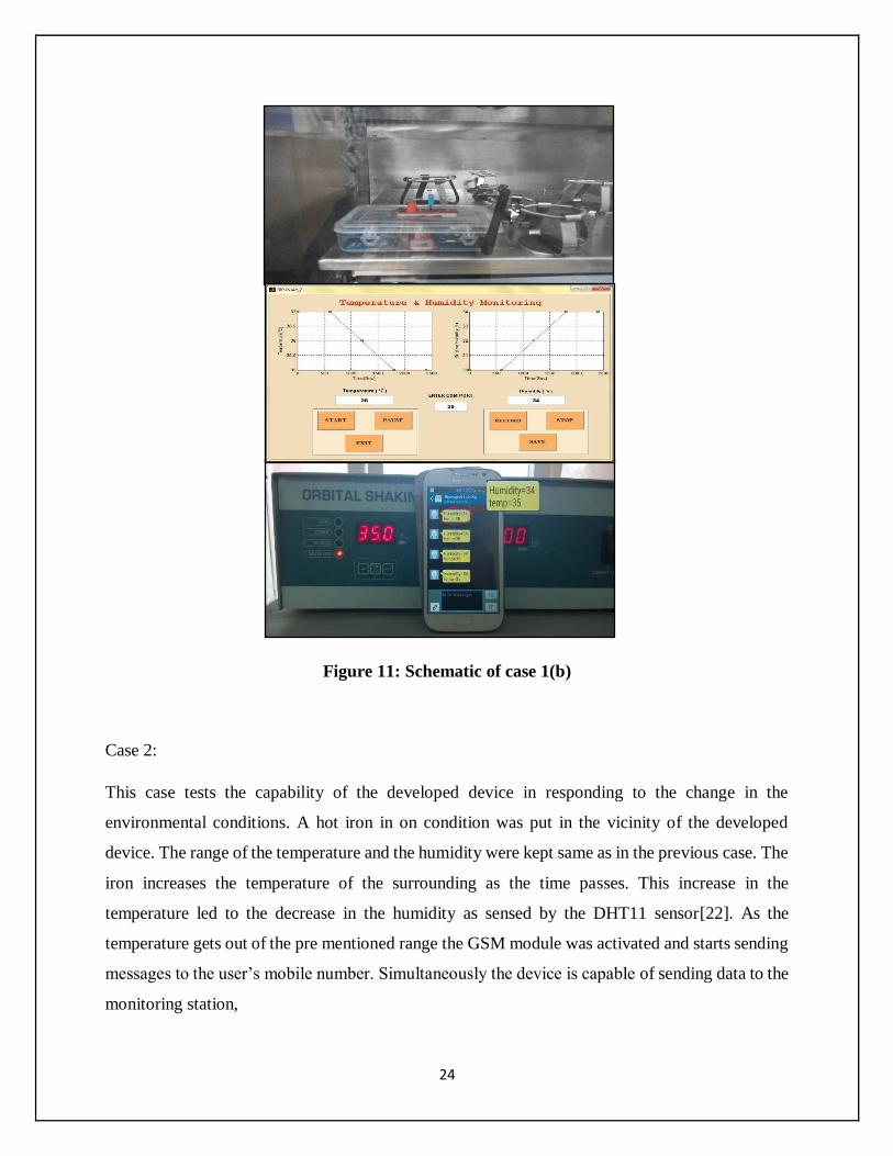
Figure 11: Schematic of case 1(b)
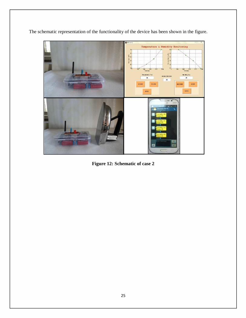
Case 2:
This case tests the capability of the developed device in responding to the change in the
environmental conditions. A hot iron in on condition was put in the vicinity of the developed
device. The range of the temperature and the humidity were kept same as in the previous case. The
iron increases the temperature of the surrounding as the time passes. This increase in the
temperature led to the decrease in the humidity as sensed by the DHT11 sensor[22]. As the
temperature gets out of the pre mentioned range the GSM module was activated and starts sending
messages to the user’s mobile number. Simultaneously the device is capable of sending data to the
monitoring station,
25
The schematic representation of the functionality of the device has been shown in the figure.
Figure 12: Schematic of case 2

26
CHAPTER 5
CONCLUSION
27
5. CONCLUSION
The designing of an intelligent temperature-cum-humidity monitoring system is depicted in this
current project. The designing of the fully functional prototype is developed in-house. Once the
humidity of the temperature gets out of the range mentioned by the user the device sends a SMS
to the user’s predefined number[8]. This SMS contains information of the current temperature and
the humidity. The developed device is also able to send the data to the monitoring station for
recording and graph plotting for analyzing purposes at the later stage. The developed device has
been tested under various simulated conditions.
28
REFERENCES
[1] F. J. Arregui, I. R. Matias, K. L. Cooper, and R. O. Claus, "Simultaneous measurement of
humidity and temperature by combining a reflective intensity-based optical fiber sensor
and a fiber Bragg grating," Sensors Journal, IEEE, vol. 2, pp. 482-487, 2002.
[2] S. Madkar and R. Prasad, "A State of Art on Design of Low Cost Transceiver for Data
Acquisition in WSN."
[3] T. Zwavashe and R. Duri, "Integrating GSM and Zigbee Wireless Networks for Smart A2
farming Enterprises in Zimbabwe," International Journal of Science and Research, Vol3,
Issue6, 2014.
[4] N. H. A. Aziz, W. N. W. Muhamad, N. A. Wahab, A. J. Alias, A. T. Hashim, and R.
Mustafa, "Real time monitoring critical parameters in tissue culture growth room with
SMS alert system," in Intelligent Systems, Modelling and Simulation (ISMS), 2010
International Conference on, 2010, pp. 339-343.
[5] E. Parrish and T. Hickey, "A Temperature Monitoring System for Use on Normal
Newborn Infants," Instrumentation and Measurement, IEEE Transactions on, vol. 21, pp.
59-60, 1972.
[6] L. Ruiz-Garcia, P. Barreiro, and J. Robla, "Performance of ZigBee-based wireless sensor
nodes for real-time monitoring of fruit logistics," Journal of Food Engineering, vol. 87,
pp. 405-415, 2008.
[7] N. Zarka, I. Al-Houshi, and M. Akhkobek, "Temperature control via sms," in Information
and Communication Technologies, 2006. ICTTA'06. 2nd, 2006, pp. 2678-2683.
[8] R. K. Megalingam, V. Radhakrishnan, D. K. M. Unnikrishnan, D. C. Jacob, and A. K.
Sudhakaran, "Autonomous Smart Server Guard for advanced safety measure using
wireless mobile technology," in Mechanical and Electrical Technology (ICMET), 2010
2nd International Conference on, 2010, pp. 654-658.
[9] S. J. Brown, "Remote health monitoring and maintenance system," ed: Google Patents,
2001.
[10] M. Margolis, Arduino cookbook: " O'Reilly Media, Inc.", 2011.
[11] S. Monicka, C. Suganya, S. N. Bharathi, and A. Sindhu, "A Ubiquitous Based System for
Health Care Monitoring."
[12] J. Li, Z. Wen, C. Fan, X. Zhang, and Y. Wu, "Design and Implementation of SMSG
Based on Arduino and GPRS Shield," in LISS 2013, ed: Springer, 2015, pp. 777-782.
[13] N. Tianlong, "Application of Single Bus Sensor DHT11 in Temperature Humidity
Measure and Control System [J]," Microcontrollers & Embedded Systems, vol. 6, p. 026,
2010.
[14] Y.-m. HAN and J.-p. ZHAO, "Desiggn of temperature humidity wireless sensor network
node based on DHT11," Journal of Jinggangshan University (Natural Science), vol. 32,
pp. 67-70, 2011.
[15] N. Watthanawisuth, A. Tuantranont, and T. Kerdcharoen, "Microclimate real-time
monitoring based on ZigBee sensor network," in Sensors, 2009 IEEE, 2009, pp. 1814-
1818.
[16] C. Yi and F. Bai, "ZigBee-based CC2530 Granary Temperature and Humidity
Monitoring System [J]," Journal of Changchun University of Science and Technology
(Natural Science Edition), vol. 4, p. 016, 2011.
29
[17] M. S. Zaghloul, "GSM-GPRS Arduino Shield (GS-001) with SIM 900 chip module in
wireless data transmission system for data acquisition and control of power induction
furnace."
[18] W. Q. C. Z. C. Xin, "Design of Warehouse Temperature and Humidity Acquisition
System Based on ZigBee [J]," Computer & Digital Engineering, vol. 9, p. 056, 2009.
[19] D. M. F. M. B. Mahmood, "Data Acquisition of Greenhouse Using Arduino."
[20] Y.-L. Hsu, C.-C. Yang, T.-C. Tsai, C.-M. Cheng, and C.-H. Wu, "Development of a
decentralized telehomecare monitoring system," Telemedicine and e-Health, vol. 13, pp.
69-78, 2007.
[21] J.-s. YANG and Z.-h. TIAN, "Wireless Remote Monitor System of Temperature and
Humidity Based on SHT71 [J]," Journal of Tianjin University of Science & Technology,
vol. 2, p. 015, 2009.
[22] D. Yu-fang, "nRF905 & DHT11 based wireless temperature & humidity logger,"
Information Technology, vol. 8, p. 057, 2012.