Embed Size (px)
Citation preview
Journal of China University of Science and Technology Vol.50-2012.01
61
Design the Progressive Addition Hard Contact Lens for Myopic Presbyopia
應用於近視性老花眼的多焦點硬式隱形眼鏡設計應用於近視性老花眼的多焦點硬式隱形眼鏡設計應用於近視性老花眼的多焦點硬式隱形眼鏡設計應用於近視性老花眼的多焦點硬式隱形眼鏡設計
��� 1 ��� 2 �� � 3
Chia-Tsung Hung Der-Chin Chen Shih-Wen Lee �� ���� ����� ��� �� ���� ����� �� !� ���� �"#��1,2Department of Electrical Engineering, Feng Chia University
3Department of Electrical Engineering, China University of Science and Technology
ABSTRACT
The purpose of this study is to design the progressive addition hard contact lens for
myopic presbyopia patients by using the multi-configuration function in ZEMAX
optical design program. The multi-configuration settings consist of four ranges, which
are infinity, 2000mm, 1000mm and 400mm. So, the myopic presbyopia patients are able
to see clearly under the four different fields of view after wearing progressive addition
hard contact lens. Using the methods of multi-configuration and the free form surface;
it could correct the -3.00D at the infinity and -1.0D at the near vision of myopia
presbyopia, and the Modulation Transfer Function (MTF) value can reach above 0.3 at
30lp/mm. And super progressive addition hard contact lenses are designed.
Key Word: Progressive Lens, Myopic presbyopia, Freeform
摘摘摘摘 要要要要
本文研究目的係使用自由曲面最佳化設計一近視性老花眼硬式隱形眼鏡。$%&'() *ZEMAX +,-./ 01234 567 89 :2000mm:1000mm:
400mm;4種視場(View Field)進行設計,使近視性老花眼在配戴硬式隱形眼鏡後後
也適合看遠、中、近距離。除了可矯正近視 Myopia(-3.00D)之外,還可以使配戴近
視性老花眼硬式隱形眼鏡之後的視網膜解像率在 30 lp/mm的 MTF 值達 0.3以上。
Design the Progressive Addition Hard Contact Lens for Myopic Presbyopia
62
<=> ?@AB C DEFGHI DJKLM
I. INTRODUCTION
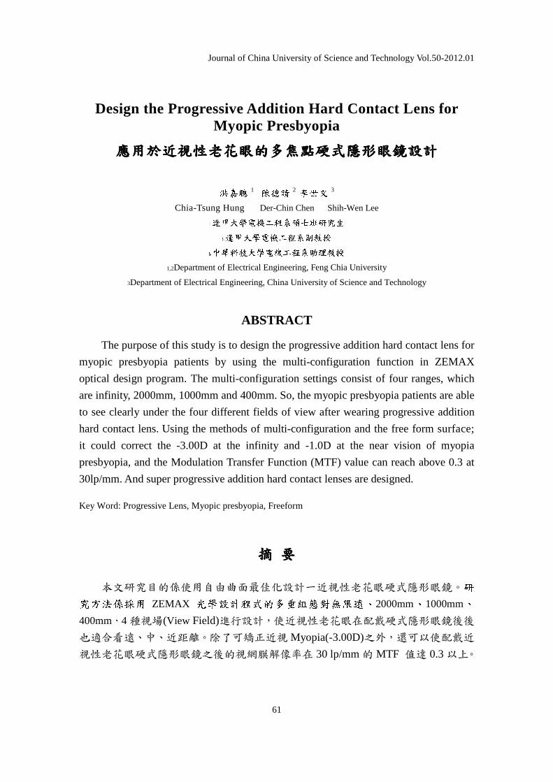
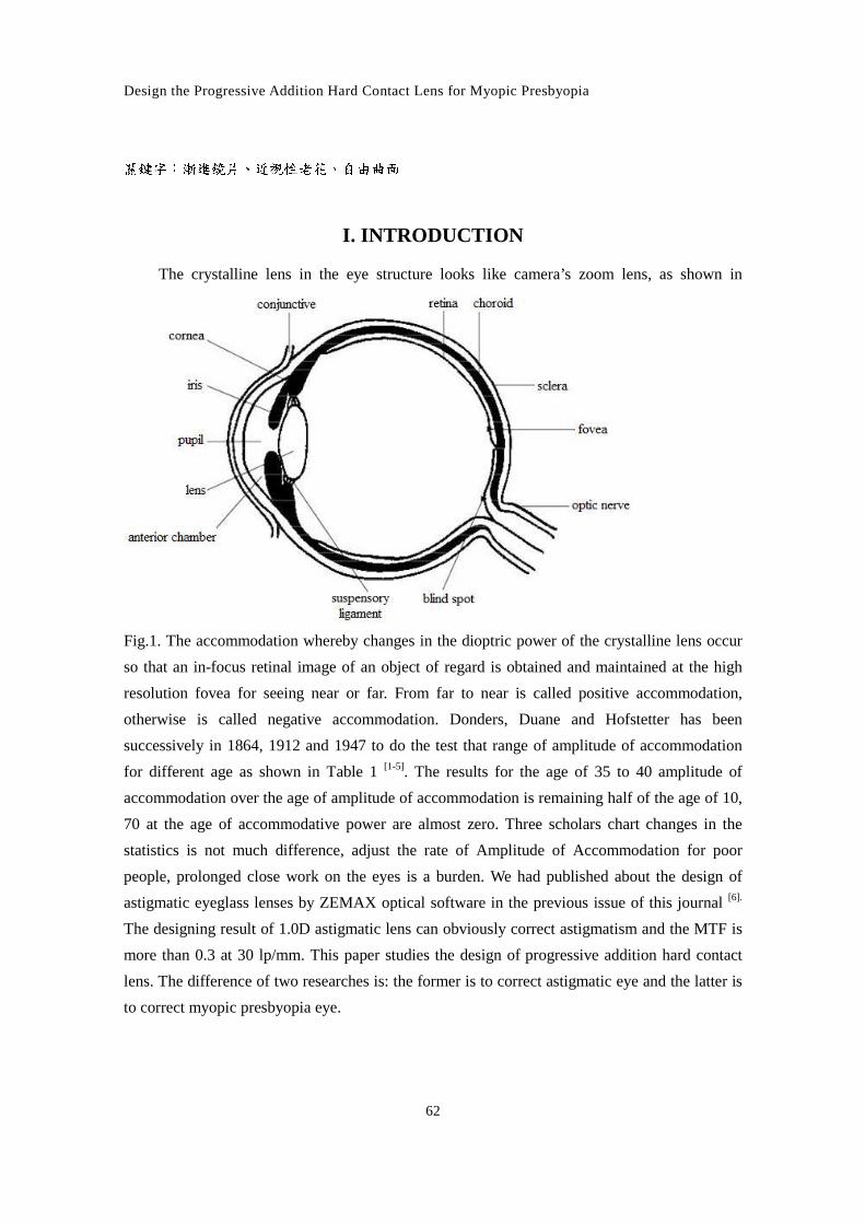
The crystalline lens in the eye structure looks like camera’s zoom lens, as shown in
Fig.1. The accommodation whereby changes in the dioptric power of the crystalline lens occur
so that an in-focus retinal image of an object of regard is obtained and maintained at the high
resolution fovea for seeing near or far. From far to near is called positive accommodation,
otherwise is called negative accommodation. Donders, Duane and Hofstetter has been
successively in 1864, 1912 and 1947 to do the test that range of amplitude of accommodation
for different age as shown in Table 1 [1-5]. The results for the age of 35 to 40 amplitude of
accommodation over the age of amplitude of accommodation is remaining half of the age of 10,
70 at the age of accommodative power are almost zero. Three scholars chart changes in the
statistics is not much difference, adjust the rate of Amplitude of Accommodation for poor
people, prolonged close work on the eyes is a burden. We had published about the design of
astigmatic eyeglass lenses by ZEMAX optical software in the previous issue of this journal [6].
The designing result of 1.0D astigmatic lens can obviously correct astigmatism and the MTF is
more than 0.3 at 30 lp/mm. This paper studies the design of progressive addition hard contact
lens. The difference of two researches is: the former is to correct astigmatic eye and the latter is
to correct myopic presbyopia eye.
Journal of China University of Science and Technology Vol.50-2012.01
63
Fig.1 the structure of the eye
Design the Progressive Addition Hard Contact Lens for Myopic Presbyopia
64
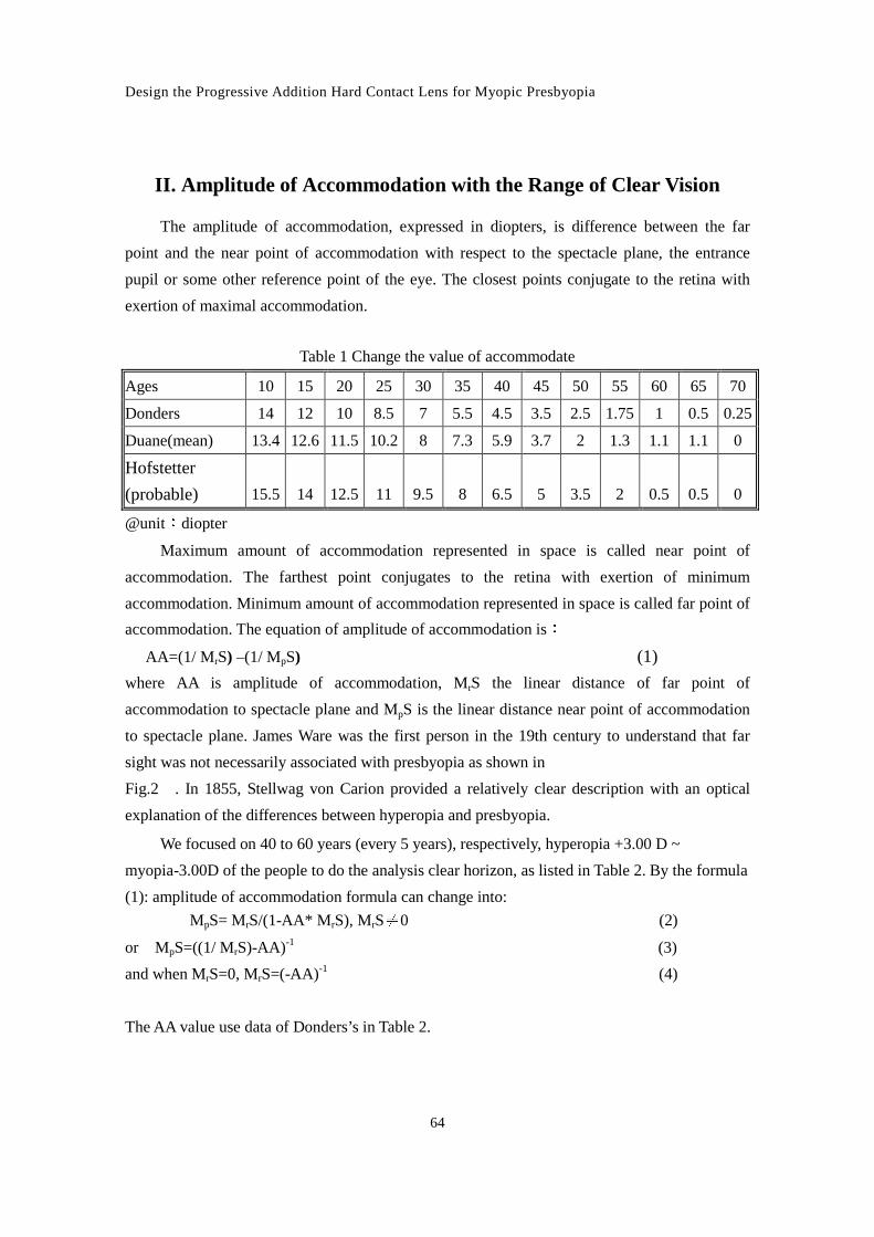
II. Amplitude of Accommodation with the Range of Clear Vision
The amplitude of accommodation, expressed in diopters, is difference between the far
point and the near point of accommodation with respect to the spectacle plane, the entrance
pupil or some other reference point of the eye. The closest points conjugate to the retina with
exertion of maximal accommodation.
Table 1 Change the value of accommodate
Ages 10 15 20 25 30 35 40 45 50 55 60 65 70
Donders 14 12 10 8.5 7 5.5 4.5 3.5 2.5 1.75 1 0.5 0.25
Duane(mean) 13.4 12.6 11.5 10.2 8 7.3 5.9 3.7 2 1.3 1.1 1.1 0
Hofstetter
(probable) 15.5 14 12.5 11 9.5 8 6.5 5 3.5 2 0.5 0.5 0
@unit Ndiopter
Maximum amount of accommodation represented in space is called near point of
accommodation. The farthest point conjugates to the retina with exertion of minimum
accommodation. Minimum amount of accommodation represented in space is called far point of
accommodation. The equation of amplitude of accommodation isN
AA=(1/ MrS) –(1/ MpS) (1) where AA is amplitude of accommodation, MrS the linear distance of far point of
accommodation to spectacle plane and MpS is the linear distance near point of accommodation
to spectacle plane. James Ware was the first person in the 19th century to understand that far
sight was not necessarily associated with presbyopia as shown in
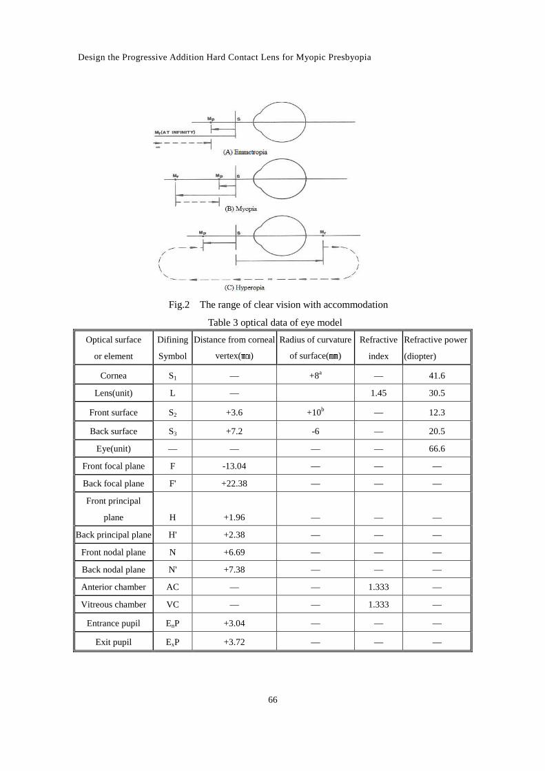
Fig.2 . In 1855, Stellwag von Carion provided a relatively clear description with an optical
explanation of the differences between hyperopia and presbyopia.
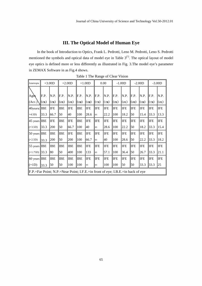
We focused on 40 to 60 years (every 5 years), respectively, hyperopia +3.00 D ~
myopia-3.00D of the people to do the analysis clear horizon, as listed in Table 2. By the formula
(1): amplitude of accommodation formula can change into:
MpS= MrS/(1-AA* M rS), MrSO0 (2)
or MpS=((1/ MrS)-AA)-1 (3)
and when MrS=0, MrS=(-AA)-1 (4)
The AA value use data of Donders’s in Table 2.
Journal of China University of Science and Technology Vol.50-2012.01
65
III. The Optical Model of Human Eye
In the book of Introduction to Optics, Frank L. Pedrotti, Leno M. Pedrotti, Leno S. Pedrotti
mentioned the symbols and optical data of model eye in Table 3[7]. The optical layout of model
eye optics is defined more or less differently as illustrated in Fig. 3.The model eye’s parameter
in ZEMAX Software in as Fig.4 shows.
Table 1 The Range of Clear Vision
Ametropia +3.00D +2.00D +1.00D 0.00 -1.00D -2.00D -3.00D
Ages
(Acc.)
F.P.
(P )
N.P.
(P )
F.P.
(P )
N.P.
(P )
F.P.
(P )
N.P.
(P )
F.P.
(P )
N.P.
(P )
F.P.
(P )
N.P.
(P )
F.P.
(P )
N.P.
(P )
F.P.
(P )
N.P.
(P )
40years(
+4.5D)
IBE
33.3
IFE
66.7
IBE
50
IFE
40
IBE
100
IFE
28.6
IFE
∞
IFE
22.2
IFE
100
IFE
18.2
IFE
50
IFE
15.4
IFE
33.3
IFE
13.3
45 years
(+3.5D)
IBE
33.3
IFE
200
IBE
50
IFE
66.7
IBE
100
IFE
40
IFE
∞
IFE
28.6
IFE
100
IFE
22.2
IFE
50
IFE
18.2
IFE
33.3
IFE
15.4
50 years
(+2.5D)
IBE
33.3
IBE
200
IBE
50
IFE
200
IBE
100
IFE
66.7
IFE
∞
IFE
40
IFE
100
IFE
28.6
IFE
50
IFE
22.2
IFE
33.3
IFE
18.2
55 years
(+1.75D)
IBE
33.3
IBE
80
IBE
50
IBE
400
IBE
100
IFE
133
IFE
∞
IFE
57.1
IFE
100
IFE
36.4
IFE
50
IFE
26.7
IFE
33.3
IFE
21.1
60 years
(+1D)
IBE
33.3
IBE
50
IBE
50
IBE
100
IBE
100
IFE
∞
IFE
∞
IFE
100
IFE
100
IFE
50
IFE
50
IFE
33.3
IFE
33.3
IFE
25
F.P.=Far Point; N.P.=Near Point; I.F.E.=in front of eye; I.B.E.=in back of eye
Design the Progressive Addition Hard Contact Lens for Myopic Presbyopia
66
Fig.2 The range of clear vision with accommodation
Table 3 optical data of eye model
Optical surface
or element
Difining
Symbol
Distance from corneal
vertex(Q )
Radius of curvature
of surface(Q )
Refractive
index
Refractive power
(diopter)
Cornea S1 — +8a — 41.6
Lens(unit) L — 1.45 30.5
Front surface S2 +3.6 +10b — 12.3
Back surface S3 +7.2 -6 — 20.5
Eye(unit) — — — — 66.6
Front focal plane F -13.04 — — —
Back focal plane F' +22.38 — — —
Front principal
plane H +1.96 — — —
Back principal plane H' +2.38 — — —
Front nodal plane N +6.69 — — —
Back nodal plane N' +7.38 — — —
Anterior chamber AC — — 1.333 —
Vitreous chamber VC — — 1.333 —
Entrance pupil EnP +3.04 — — —
Exit pupil ExP +3.72 — — —
Journal of China University of Science and Technology Vol.50-2012.01
67
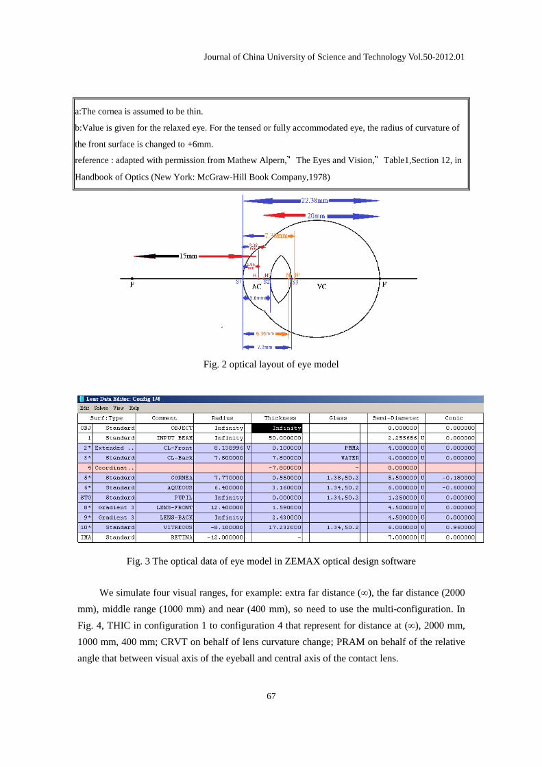
a:The cornea is assumed to be thin.
b:Value is given for the relaxed eye. For the tensed or fully accommodated eye, the radius of curvature of
the front surface is changed to +6mm.
reference : adapted with permission from Mathew Alpern,RThe Eyes and Vision,RTable1,Section 12, in
Handbook of Optics (New York: McGraw-Hill Book Company,1978)
Fig. 2 optical layout of eye model
Fig. 3 The optical data of eye model in ZEMAX optical design software
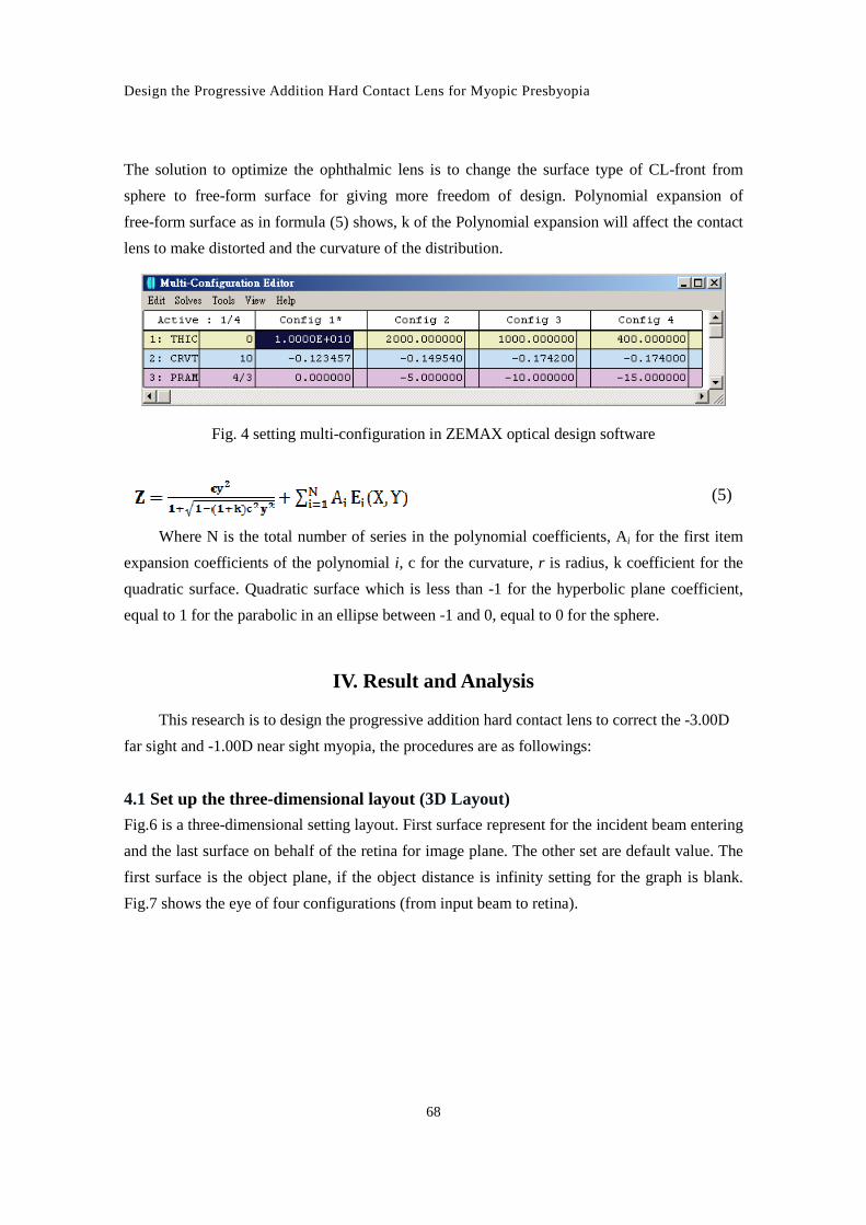
We simulate four visual ranges, for example: extra far distance (∞), the far distance (2000
mm), middle range (1000 mm) and near (400 mm), so need to use the multi-configuration. In
Fig. 4, THIC in configuration 1 to configuration 4 that represent for distance at (∞), 2000 mm,
1000 mm, 400 mm; CRVT on behalf of lens curvature change; PRAM on behalf of the relative
angle that between visual axis of the eyeball and central axis of the contact lens.
Design the Progressive Addition Hard Contact Lens for Myopic Presbyopia
68
The solution to optimize the ophthalmic lens is to change the surface type of CL-front from
sphere to free-form surface for giving more freedom of design. Polynomial expansion of
free-form surface as in formula (5) shows, k of the Polynomial expansion will affect the contact
lens to make distorted and the curvature of the distribution.
Fig. 4 setting multi-configuration in ZEMAX optical design software
(5)
Where N is the total number of series in the polynomial coefficients, Ai for the first item
expansion coefficients of the polynomial i, c for the curvature, r is radius, k coefficient for the
quadratic surface. Quadratic surface which is less than -1 for the hyperbolic plane coefficient,
equal to 1 for the parabolic in an ellipse between -1 and 0, equal to 0 for the sphere.
IV. Result and Analysis
This research is to design the progressive addition hard contact lens to correct the -3.00D
far sight and -1.00D near sight myopia, the procedures are as followings:
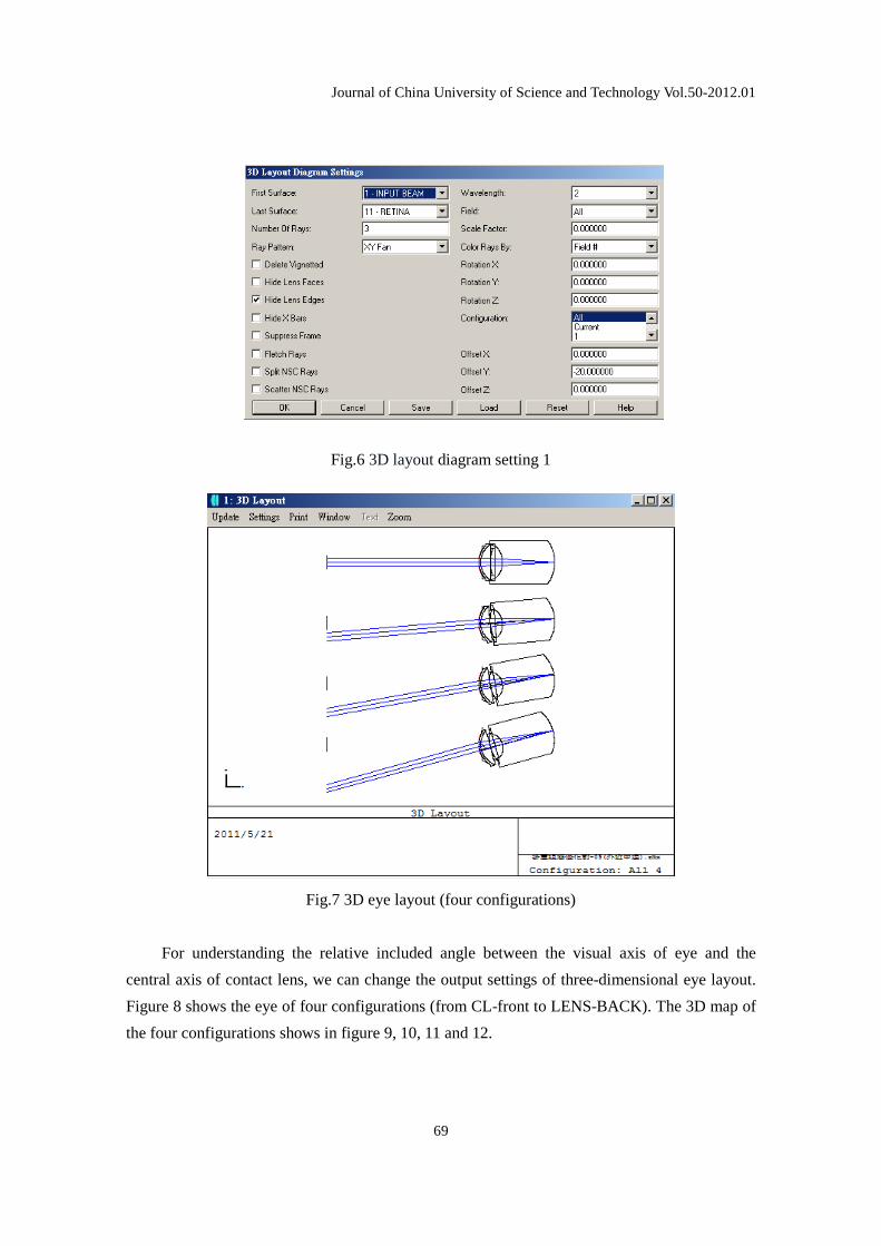
4.1 Set up the three-dimensional layout (3D Layout)
Fig.6 is a three-dimensional setting layout. First surface represent for the incident beam entering
and the last surface on behalf of the retina for image plane. The other set are default value. The
first surface is the object plane, if the object distance is infinity setting for the graph is blank.
Fig.7 shows the eye of four configurations (from input beam to retina).
Journal of China University of Science and Technology Vol.50-2012.01
69
Fig.6 3D layout diagram setting 1
Fig.7 3D eye layout (four configurations)
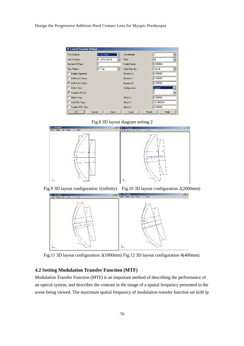
For understanding the relative included angle between the visual axis of eye and the
central axis of contact lens, we can change the output settings of three-dimensional eye layout.
Figure 8 shows the eye of four configurations (from CL-front to LENS-BACK). The 3D map of
the four configurations shows in figure 9, 10, 11 and 12.
Design the Progressive Addition Hard Contact Lens for Myopic Presbyopia
70
Fig.8 3D layout diagram setting 2
Fig.9 3D layout configuration 1(infinity) Fig.10 3D layout configuration 2(2000mm)
Fig.11 3D layout configuration 3(1000mm) Fig.12 3D layout configuration 4(400mm)
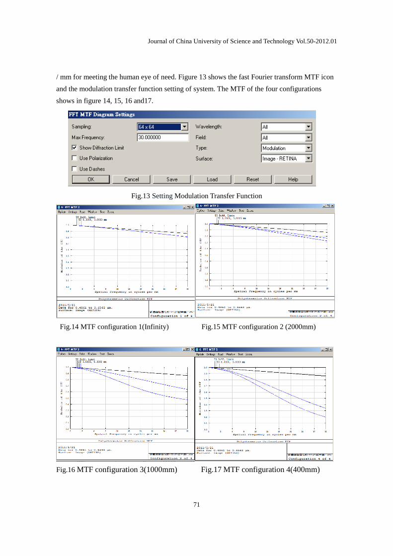
4.2 Setting Modulation Transfer Function (MTF)
Modulation Transfer Function (MTF) is an important method of describing the performance of
an optical system, and describes the contrast in the image of a spatial frequency presented in the
scene being viewed. The maximum spatial frequency of modulation transfer function set in30 lp
Journal of China University of Science and Technology Vol.50-2012.01
71
/ mm for meeting the human eye of need. Figure 13 shows the fast Fourier transform MTF icon
and the modulation transfer function setting of system. The MTF of the four configurations
shows in figure 14, 15, 16 and17.
Fig.13 Setting Modulation Transfer Function
Fig.14 MTF configuration 1(Infinity) Fig.15 MTF configuration 2 (2000mm)
Fig.16 MTF configuration 3(1000mm) Fig.17 MTF configuration 4(400mm)
Design the Progressive Addition Hard Contact Lens for Myopic Presbyopia
72
The MTF plot for this eye glass, above, shows the contrast ratio for any spatial frequency
up to the maximum that the eye glass can support. In this case, we choose to limit the spatial
frequencies shown to a maximum of 30 cycles/mm. Also shown for reference is the diffraction
limited performance of an aberration-free lens of the same f/# [8].
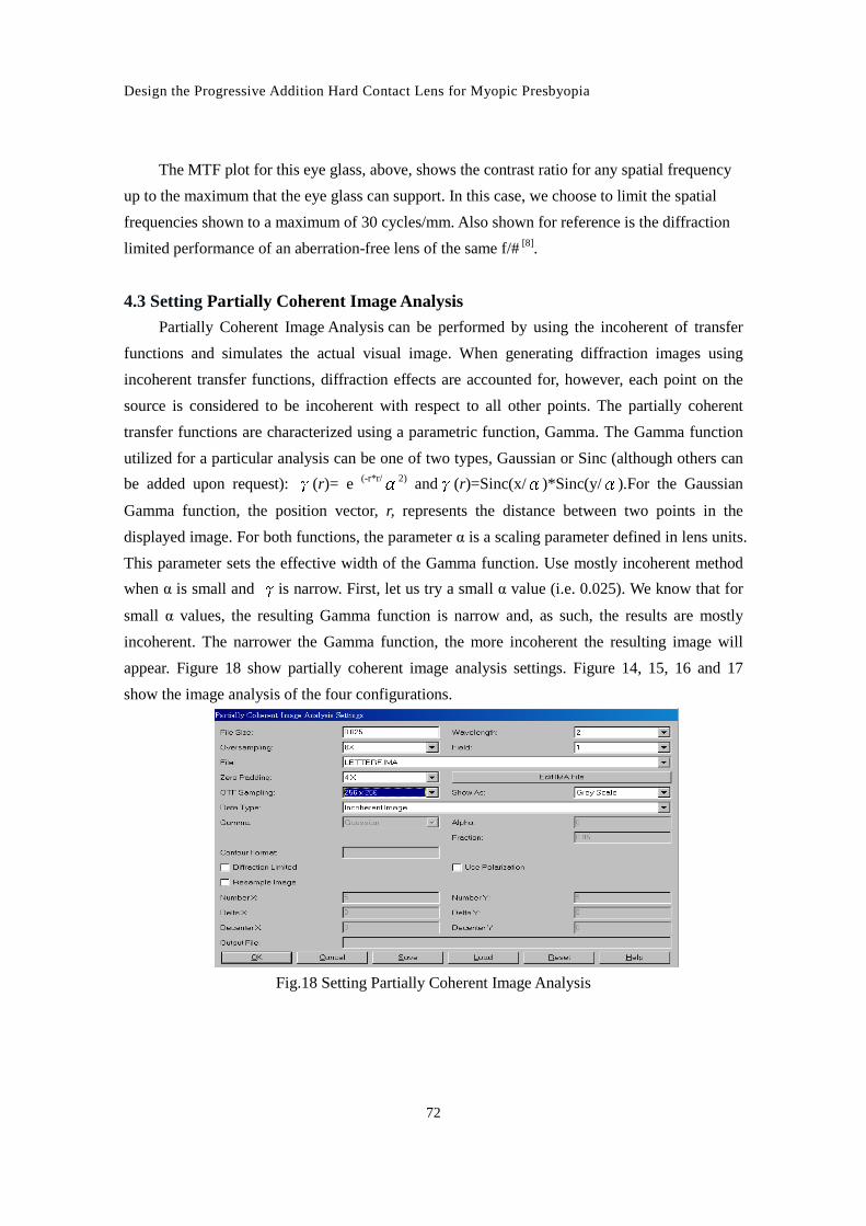
4.3 Setting Partially Coherent Image Analysis
Partially Coherent Image Analysis can be performed by using the incoherent of transfer
functions and simulates the actual visual image. When generating diffraction images using
incoherent transfer functions, diffraction effects are accounted for, however, each point on the
source is considered to be incoherent with respect to all other points. The partially coherent
transfer functions are characterized using a parametric function, Gamma. The Gamma function
utilized for a particular analysis can be one of two types, Gaussian or Sinc (although others can
be added upon request): S(r)= e (-r*r/ T2) andS(r)=Sinc(x/T)*Sinc(y/T).For the Gaussian
Gamma function, the position vector, r, represents the distance between two points in the
displayed image. For both functions, the parameter α is a scaling parameter defined in lens units.
This parameter sets the effective width of the Gamma function. Use mostly incoherent method
when α is small and Sis narrow. First, let us try a small α value (i.e. 0.025). We know that for
small α values, the resulting Gamma function is narrow and, as such, the results are mostly
incoherent. The narrower the Gamma function, the more incoherent the resulting image will
appear. Figure 18 show partially coherent image analysis settings. Figure 14, 15, 16 and 17
show the image analysis of the four configurations.
Fig.18 Setting Partially Coherent Image Analysis
Journal of China University of Science and Technology Vol.50-2012.01
73
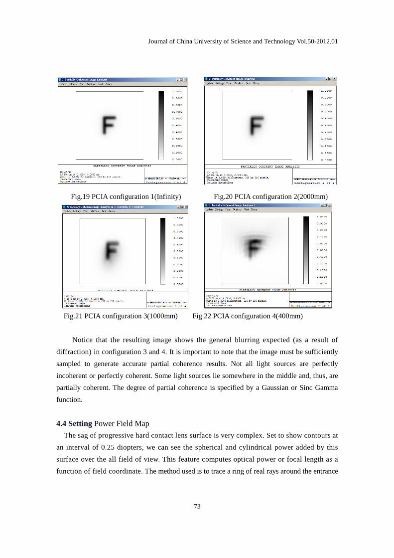
Fig.19 PCIA configuration 1(Infinity) Fig.20 PCIA configuration 2(2000mm)
Fig.21 PCIA configuration 3(1000mm) Fig.22 PCIA configuration 4(400mm)
Notice that the resulting image shows the general blurring expected (as a result of
diffraction) in configuration 3 and 4. It is important to note that the image must be sufficiently
sampled to generate accurate partial coherence results. Not all light sources are perfectly
incoherent or perfectly coherent. Some light sources lie somewhere in the middle and, thus, are
partially coherent. The degree of partial coherence is specified by a Gaussian or Sinc Gamma
function.
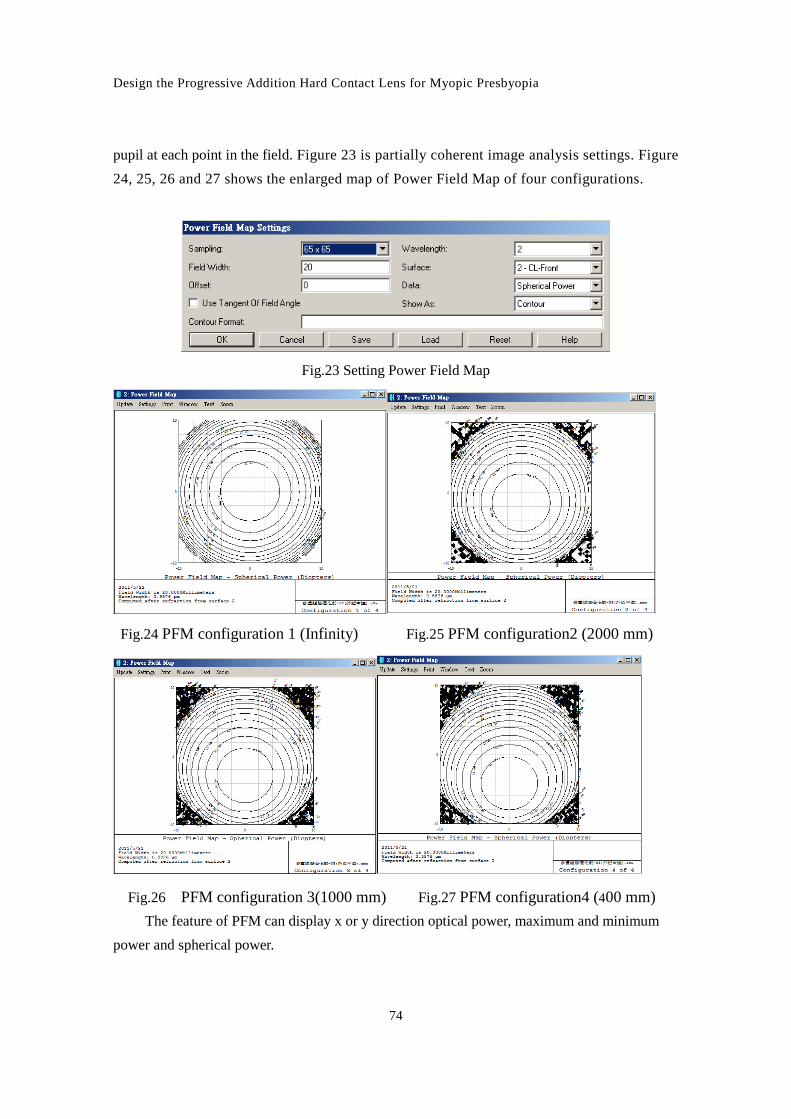
4.4 Setting Power Field Map
The sag of progressive hard contact lens surface is very complex. Set to show contours at
an interval of 0.25 diopters, we can see the spherical and cylindrical power added by this
surface over the all field of view. This feature computes optical power or focal length as a
function of field coordinate. The method used is to trace a ring of real rays around the entrance
Design the Progressive Addition Hard Contact Lens for Myopic Presbyopia
74
pupil at each point in the field. Figure 23 is partially coherent image analysis settings. Figure
24, 25, 26 and 27 shows the enlarged map of Power Field Map of four configurations.
Fig.23 Setting Power Field Map
Fig.24 PFM configuration 1 (Infinity) Fig.25 PFM configuration2 (2000 mm)
Fig.26 PFM configuration 3(1000 mm) Fig.27 PFM configuration4 (400 mm)
The feature of PFM can display x or y direction optical power, maximum and minimum
power and spherical power.
Journal of China University of Science and Technology Vol.50-2012.01
75
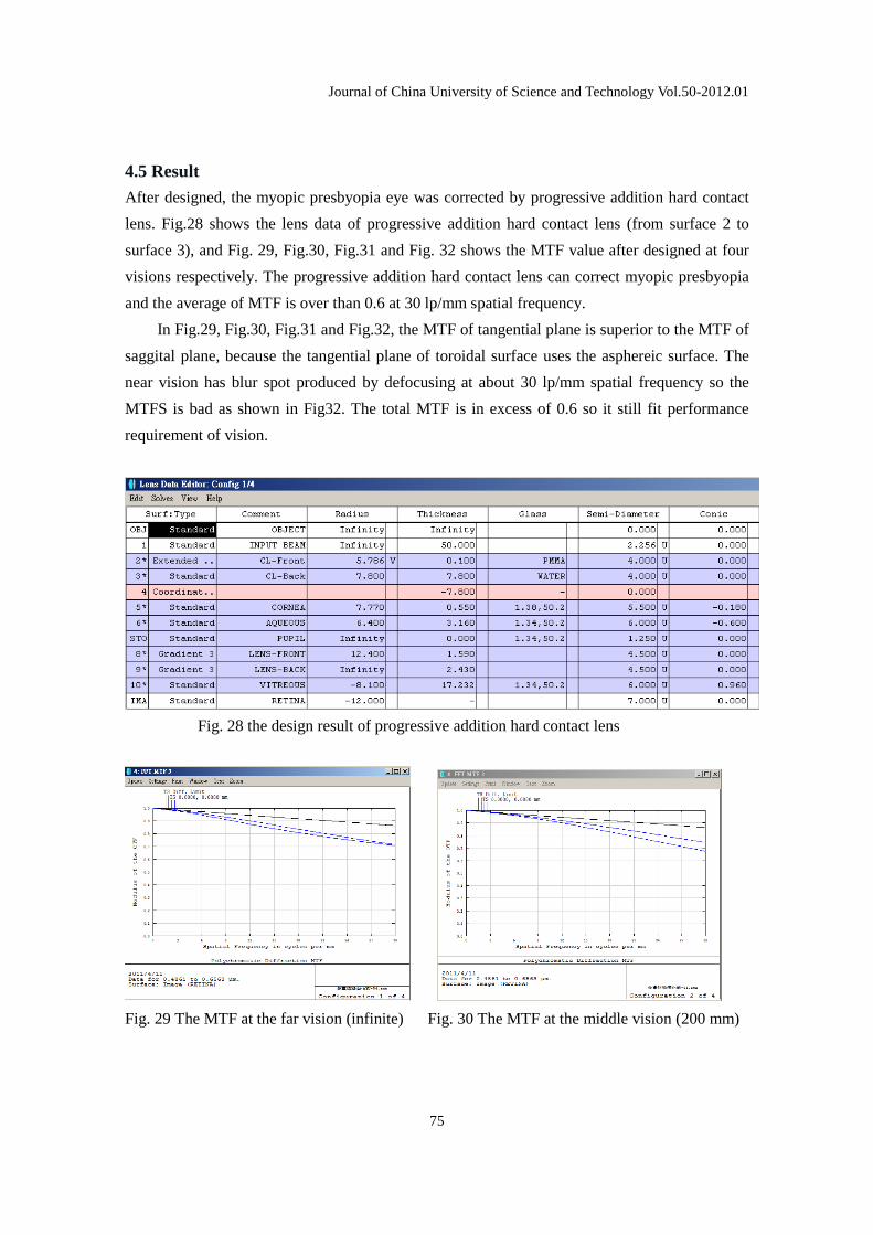
4.5 Result
After designed, the myopic presbyopia eye was corrected by progressive addition hard contact
lens. Fig.28 shows the lens data of progressive addition hard contact lens (from surface 2 to
surface 3), and Fig. 29, Fig.30, Fig.31 and Fig. 32 shows the MTF value after designed at four
visions respectively. The progressive addition hard contact lens can correct myopic presbyopia
and the average of MTF is over than 0.6 at 30 lp/mm spatial frequency.
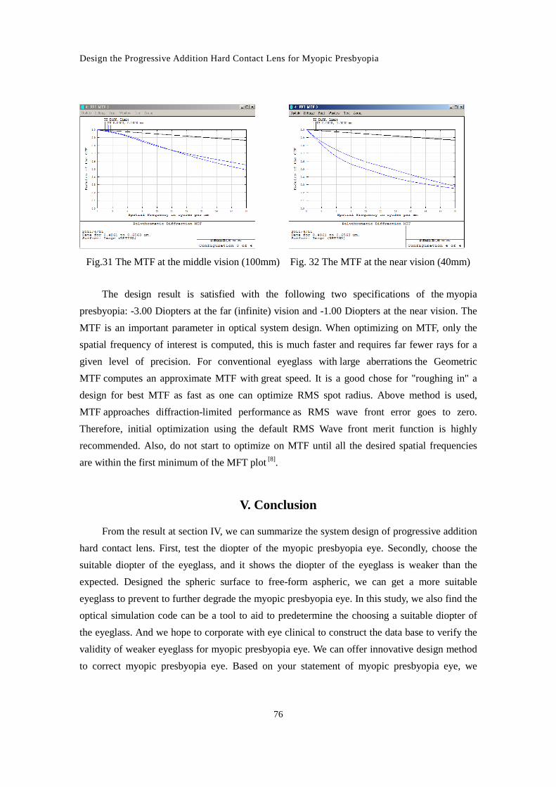
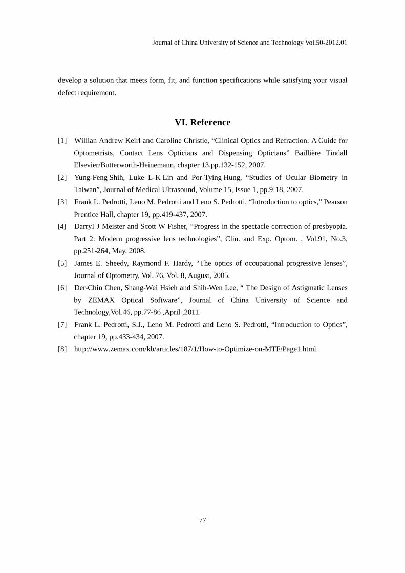
In Fig.29, Fig.30, Fig.31 and Fig.32, the MTF of tangential plane is superior to the MTF of
saggital plane, because the tangential plane of toroidal surface uses the asphereic surface. The
near vision has blur spot produced by defocusing at about 30 lp/mm spatial frequency so the
MTFS is bad as shown in Fig32. The total MTF is in excess of 0.6 so it still fit performance
requirement of vision.
Fig. 28 the design result of progressive addition hard contact lens
Fig. 29 The MTF at the far vision (infinite) Fig. 30 The MTF at the middle vision (200 mm)
Design the Progressive Addition Hard Contact Lens for Myopic Presbyopia
76
Fig.31 The MTF at the middle vision (100mm) Fig. 32 The MTF at the near vision (40mm)
The design result is satisfied with the following two specifications of the myopia
presbyopia: -3.00 Diopters at the far (infinite) vision and -1.00 Diopters at the near vision. The
MTF is an important parameter in optical system design. When optimizing on MTF, only the
spatial frequency of interest is computed, this is much faster and requires far fewer rays for a
given level of precision. For conventional eyeglass with large aberrations the Geometric
MTF computes an approximate MTF with great speed. It is a good chose for "roughing in" a
design for best MTF as fast as one can optimize RMS spot radius. Above method is used,
MTF approaches diffraction-limited performance as RMS wave front error goes to zero.
Therefore, initial optimization using the default RMS Wave front merit function is highly
recommended. Also, do not start to optimize on MTF until all the desired spatial frequencies
are within the first minimum of the MFT plot [8].
V. Conclusion
From the result at section IV, we can summarize the system design of progressive addition
hard contact lens. First, test the diopter of the myopic presbyopia eye. Secondly, choose the
suitable diopter of the eyeglass, and it shows the diopter of the eyeglass is weaker than the
expected. Designed the spheric surface to free-form aspheric, we can get a more suitable
eyeglass to prevent to further degrade the myopic presbyopia eye. In this study, we also find the
optical simulation code can be a tool to aid to predetermine the choosing a suitable diopter of
the eyeglass. And we hope to corporate with eye clinical to construct the data base to verify the
validity of weaker eyeglass for myopic presbyopia eye. We can offer innovative design method
to correct myopic presbyopia eye. Based on your statement of myopic presbyopia eye, we
Journal of China University of Science and Technology Vol.50-2012.01
77
develop a solution that meets form, fit, and function specifications while satisfying your visual
defect requirement.
VI. Reference
[1] Willian Andrew Keirl and Caroline Christie, “Clinical Optics and Refraction: A Guide for
Optometrists, Contact Lens Opticians and Dispensing Opticians” Baillière Tindall
Elsevier/Butterworth-Heinemann, chapter 13.pp.132-152, 2007.
[2] Yung-Feng Shih, Luke L-K Lin and Por-Tying Hung, “Studies of Ocular Biometry in
Taiwan”, Journal of Medical Ultrasound, Volume 15, Issue 1, pp.9-18, 2007.
[3] Frank L. Pedrotti, Leno M. Pedrotti and Leno S. Pedrotti, “Introduction to optics,” Pearson
Prentice Hall, chapter 19, pp.419-437, 2007.
[4] DarryI J Meister and Scott W Fisher, “Progress in the spectacle correction of presbyopia.
Part 2: Modern progressive lens technologies”, Clin. and Exp. Optom. , Vol.91, No.3,
pp.251-264, May, 2008.
[5] James E. Sheedy, Raymond F. Hardy, “The optics of occupational progressive lenses”,
Journal of Optometry, Vol. 76, Vol. 8, August, 2005.
[6] Der-Chin Chen, Shang-Wei Hsieh and Shih-Wen Lee, “ The Design of Astigmatic Lenses
by ZEMAX Optical Software”, Journal of China University of Science and
Technology,Vol.46, pp.77-86 ,April ,2011.
[7] Frank L. Pedrotti, S.J., Leno M. Pedrotti and Leno S. Pedrotti, “Introduction to Optics”,
chapter 19, pp.433-434, 2007.
[8] http://www.zemax.com/kb/articles/187/1/How-to-Optimize-on-MTF/Page1.html.