Embed Size (px)
Citation preview

Design Strategies for High Availability: Accommodating In-Vessel Piping Services
and Auxiliary Systems
Tom Brown Princeton Plasma Physics Laboratory
3rd IAEA-DEMO Program workshop 11-14 May 2015
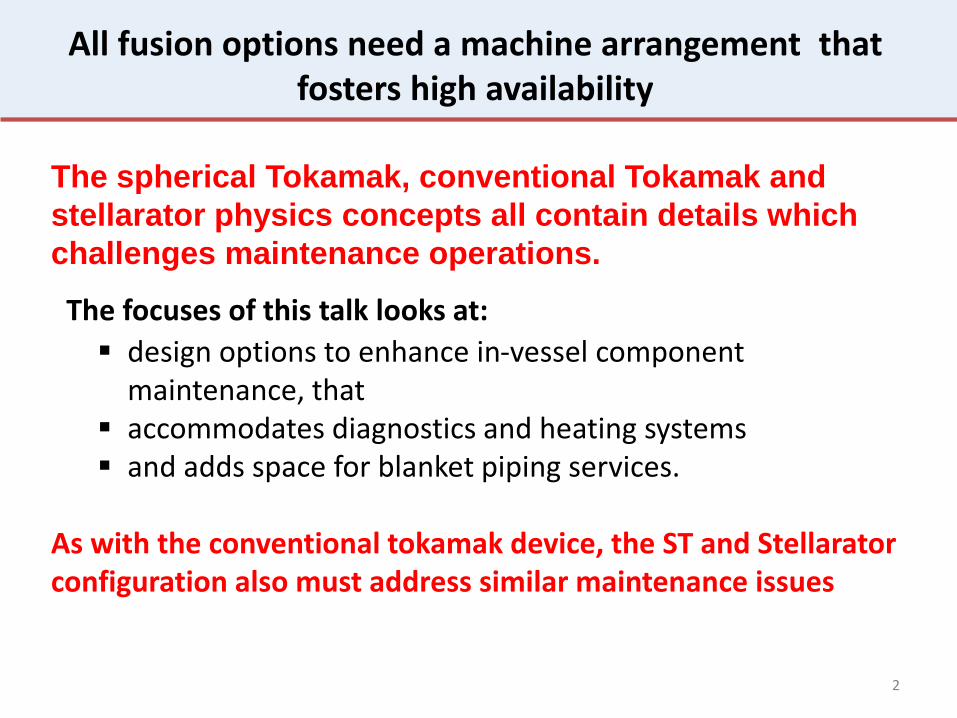
All fusion options need a machine arrangement that fosters high availability
The spherical Tokamak, conventional Tokamak and
stellarator physics concepts all contain details which
challenges maintenance operations.
As with the conventional tokamak device, the ST and Stellarator configuration also must address similar maintenance issues
2
design options to enhance in-vessel component maintenance, that
accommodates diagnostics and heating systems and adds space for blanket piping services.
The focuses of this talk looks at:
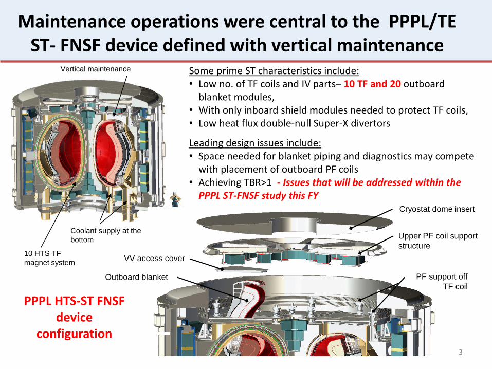
Maintenance operations were central to the PPPL/TE ST- FNSF device defined with vertical maintenance
3
10 HTS TF
magnet system
Vertical maintenance
Coolant supply at the
bottom
Cryostat dome insert
Upper PF coil support
structure
PF support off
TF coil Outboard blanket
VV access cover
Some prime ST characteristics include: • Low no. of TF coils and IV parts– 10 TF and 20 outboard
blanket modules, • With only inboard shield modules needed to protect TF coils, • Low heat flux double-null Super-X divertors
Leading design issues include: • Space needed for blanket piping and diagnostics may compete
with placement of outboard PF coils • Achieving TBR>1 - Issues that will be addressed within the
PPPL ST-FNSF study this FY
PPPL HTS-ST FNSF device
configuration
Stellarator maintenance was improved with the effort to balance plasma surface reconstructions with targeted physics
4
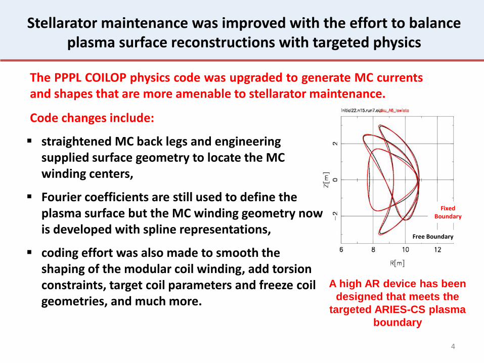
The PPPL COILOP physics code was upgraded to generate MC currents and shapes that are more amenable to stellarator maintenance.
Code changes include:
A high AR device has been
designed that meets the
targeted ARIES-CS plasma
boundary
Fixed Boundary
Free Boundary
straightened MC back legs and engineering supplied surface geometry to locate the MC winding centers,
Fourier coefficients are still used to define the plasma surface but the MC winding geometry now is developed with spline representations,
coding effort was also made to smooth the shaping of the modular coil winding, add torsion constraints, target coil parameters and freeze coil geometries, and much more.

5
Greater access improves blanket maintenance
Moving from the 3-period quasi-axisymmetric ARIES-CS parameters (A=4.5, R0 = 7.75m, B = 5.7T) to an AR 6.0 configuration while retaining fusion power, beta, plasma volume, and toroidal magnetic field leads to a 9.4m R0 device with straightened back legs for Type A and B MC’s that meets maintenance requirements and matches the targeted plasma boundary.
ARIES-CS 4.5 AR, 7.75-m Raxis
Maintaining self-consistency between engineering and physics improved maintenance feasibility
(36)

Multiple DEMO Tokamak options have been studied
Adapted from paper by Hiroyasu Utoh et. al. “Critical Design Factors for Sector Transport Maintenance in DEMO”
U.S. ARIES-AT Horizontal access
16 radially extended TF coils
Toroidal segmentation
16 modules
16-port horizontal removal
16-port vertical
maintenance
EU multi-module concept
Vertical access JAEA, DEMO
Limited horizontal access
12 radially extended TF coils
Toroidal segmentation
12 modules
4-port horizontal removal
16 close-fitting TF coils
Toroidal & radial segmentation
64 modules
16-port vertical removal
6
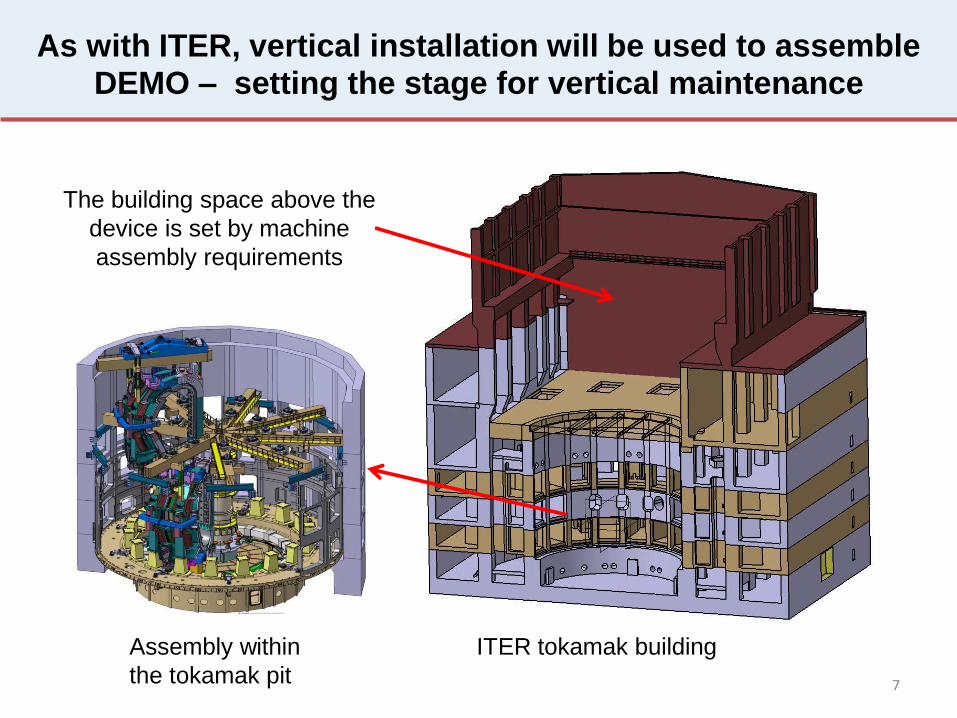
As with ITER, vertical installation will be used to assemble DEMO – setting the stage for vertical maintenance
7
The building space above the
device is set by machine
assembly requirements
Assembly within
the tokamak pit
ITER tokamak building

8
Maintenance cycle to achieve 75%
availability for planned maintenance
Maintenance duration estimate for a DEMO fusion power plant, basedon the EFDA WP12 pre-conceptual studies, O. Crofts and J. Harman, Fusion Engineering and Design 89 (2014) 2383–2387
Many features will impact maintenance Two areas addressed:
Auxiliary system interfaces Blanket piping services
All DEMO designs strive for maintenance compatible arrangements that fosters high availability
Blanket piping through upper port
EU Demo

Alternate design strategies need to be developed and evaluated
Can maintenance improve with the added space of
an enlarged VV and TF coil?
Within a vertical maintenance scheme, can
maintenance be enhanced with blanket piping
services coming from below?
Can auxiliary systems retract without dismantling
the integrated system?
9
Defining a feasible fusion design that operates with high
availability is challenging…there is a need to develop many
competing concepts in order to develop one feasible solution.
Question:
10
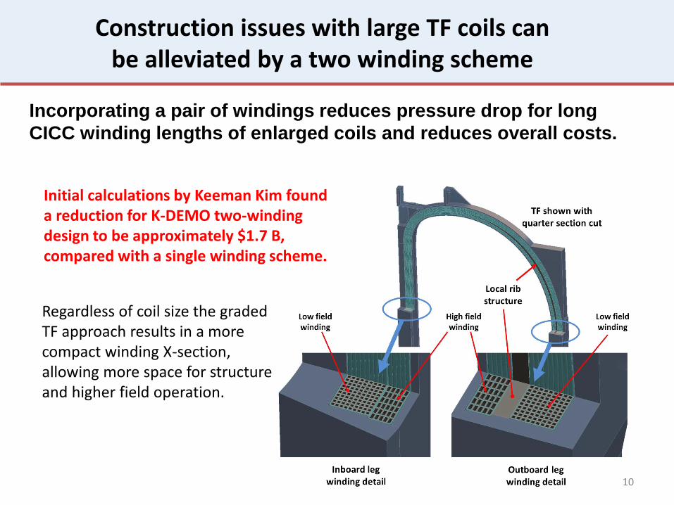
Construction issues with large TF coils can be alleviated by a two winding scheme
Incorporating a pair of windings reduces pressure drop for long
CICC winding lengths of enlarged coils and reduces overall costs.
Initial calculations by Keeman Kim found a reduction for K-DEMO two-winding design to be approximately $1.7 B, compared with a single winding scheme.
Regardless of coil size the graded TF approach results in a more compact winding X-section, allowing more space for structure and higher field operation.

11
Port requirements for H&CD and diagnostics impacts the blanket design
E. Magnani - DEMO Technical Meeting - Garching – 29,30 September 2009
Large mid-plane openings for auxiliary systems can cut the continuity of vertical blanket sector complicating piping, support and service details
EU MMS with small port opening
EU MMC with large port opening
CFETR
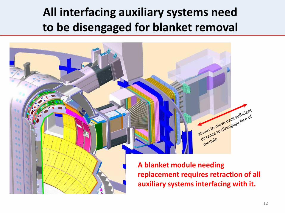
All interfacing auxiliary systems need to be disengaged for blanket removal
12
A blanket module needing replacement requires retraction of all auxiliary systems interfacing with it.
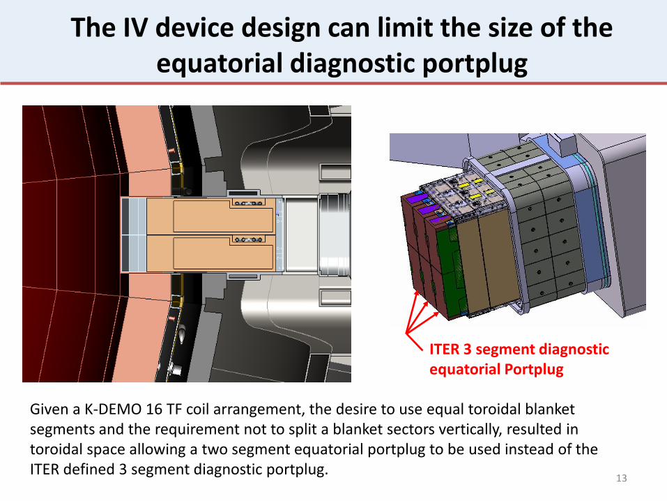
The IV device design can limit the size of the equatorial diagnostic portplug
13
Given a K-DEMO 16 TF coil arrangement, the desire to use equal toroidal blanket segments and the requirement not to split a blanket sectors vertically, resulted in toroidal space allowing a two segment equatorial portplug to be used instead of the ITER defined 3 segment diagnostic portplug.
ITER 3 segment diagnostic equatorial Portplug
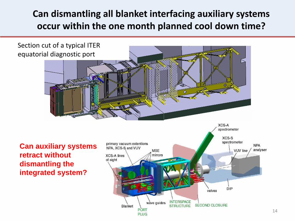
Can dismantling all blanket interfacing auxiliary systems occur within the one month planned cool down time?
14
Section cut of a typical ITER equatorial diagnostic port
Can auxiliary systems
retract without
dismantling the integrated system?

This illustration defines a concept design to disengage auxiliary systems without the need to dismantle them
15
Insert Portplug in
blanket
Retract installation
support guide
Operating position
Retract Portplug for blanket
removal
Collar outside Portplug for attachment and neutron streaming
22 tonne

K-DEMO has evolved as a vertical maintenance design with expanded space for maintenance
Design features have been added to enhance maintenance of in-vessel systems:
A structural system that supports disruption loads and provide alignment for blanket instillation has been defined,
blanket segmentation has been sized for mid-plane auxiliary port openings without splitting sectors,
blanket labyrinth interfaces has been incorporated to minimize gap streaming of neutrons, and the general arrangement
promotes a facility design that allows port auxiliary systems to retract without dismantling the auxiliary equipment
16
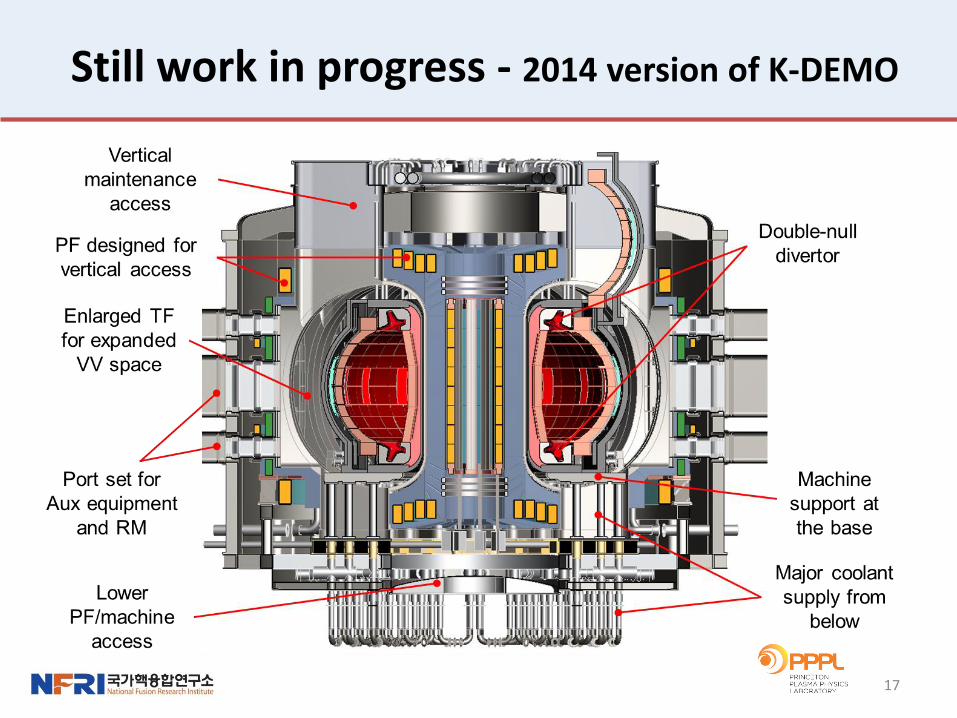
Still work in progress - 2014 version of K-DEMO
17
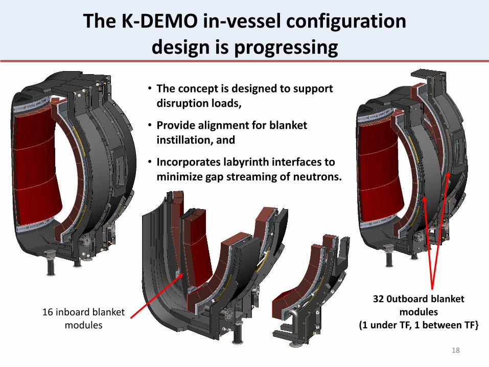
The K-DEMO in-vessel configuration design is progressing
18
• The concept is designed to support disruption loads,
• Provide alignment for blanket instillation, and
• Incorporates labyrinth interfaces to minimize gap streaming of neutrons.
16 inboard blanket modules
32 0utboard blanket modules
(1 under TF, 1 between TF}
DN vs SN present implications for physics performance and machine design
19
DN operation requires space for a second divertor, reducing tritium breeding area…and impacts divertor maintenance,
A second divertor requires added supports, maintenance and services details,
A DN arrangement requires diagnostic viewing and pumping at both locations which adds additional equipment, but
A DN divertor has symmetrical PF arrangements which allow large
vertical ports top and bottom and provides the potential to incorporate advanced divertor designs,
A DN divertor has lower heat load on the inner divertor with reduced divertor length required… increasing space for TF shielding.
A DN inboard divertor and baffle has low heat loads with an expected lifetime longer than the outer divertor segment. Can we take advantage of this?

The double-null plasma and selected blanket breeding approach impacts divertor maintenance
20
To reach TBR > 1 with K-DEMO
baseline solid breeding blankets
in a DN arrangement, divertor
modules can be replaced only by
removing some of the outboard
blanket modules.
Lower access port used to
disconnect water or LM pipes

Are there further divertor options to be considered that will enhance the device maintenance?
21
Is it feasible to split the divertor assembly in a DN arrangement to foster maintenance advantages?
Can the SN divertor be located on the top to enhance maintenance for a vertical maintained device ?
As with the ST-FNSF design, can a conventional DN tokamak be configured with a Super-X divertor?
22
Concluding remarks
For fusion to succeed not only must the plasma physics and the accompanying machine technology operate at creditable levels but the topology in which they exist must be amenable to inspection and maintenance to allow the device to operate with high availability.
All fusion devices built to date are physics centered experiments.
Serious effort is needed to look at options to define a magnetic fusion design that provides self-consistency between the plasma performance
and engineering requirements for component maintenance.
Thank you for your attention…