Embed Size (px)
Citation preview

DESIGN STANDARDS
for URBAN INFRASTRUCTURE
1 STORMWATER

Design Standards for Urban Infrastructure
1. Stormwater
1.1 Introduction 1-1 1.1.1 Objectives 1-1 1.1.2 Related Codes of Practice and Guidelines 1-2 1.1.3 Land Development 1-2 1.1.4 Conveyance Systems 1-3 1.1.5 Runoff Quantity Control 1-5 1.1.6 Runoff Quality Control 1-7 1.1.7 Ecological Considerations 1-7 1.1.8 Maintenance 1-8
1.2 Hydrology 1-8 1.2.1 Design Principles 1-8 1.2.2 Design Average Recurrence Intervals 1-8 1.2.3 Impervious Area Assumptions 1-9 1.2.4 Rational Method 1-10 1.2.5 Rainfall/Runoff Models 1-12 1.2.6 Other Methods and Models 1-16 1.2.7 Design Rainfall Intensities 1-16
1.3 Road Drainage 1-20 1.3.1 Road and Street Network 1-20 1.3.2 Surface Flow Criteria 1-20 1.3.3 Major Traffic Routes 1-20 1.3.4 Underpasses 1-23
1.4 Pipelines 1-23 1.4.1 Materials 1-23 1.4.2 Locations and Alignments 1-24 1.4.3 Drainage Easements 1-27 1.4.4 Drainage Reserves 1-28 1.4.5 Hydraulic Design 1-28 1.4.6 Grades 1-30 1.4.7 Allowable Pipe Diameters 1-30 1.4.8 Structural Design of Pipelines 1-31 1.4.9 Connection to Structures 1-32 1.4.10 Curved Pipelines 1-32 1.4.11 Branch Connections 1-32 1.4.12 Dead End Pipelines 1-33 1.4.13 Service Ties 1-33 1.4.14 Culverts 1-35
1.5 Sumps 1-37 1.5.1 General 1-37 1.5.2 Construction 1-37 1.5.3 Standard Sump Types 1-38 1.5.4 Location 1-39
1 Stormwater EDITION 1 REVISION 0
Design Standards for Urban Infrastructure
1.5.5 Maximum Spacing 1-39 1.5.6 Gutter Flow 1-40 1.5.7 Inlet Capacity 1-40 1.5.8 Fall Through Sumps 1-40 1.5.9 Benching 1-40 1.5.10 Sump Covers 1-41 1.5.11 Abandoned Sumps 1-42
1.6 Manholes 1-55 1.6.1 General 1-55 1.6.2 Construction 1-55 1.6.3 Standard Manhole Types 1-55 1.6.4 Location 1-56 1.6.5 Maximum Spacing 1-56 1.6.6 Fall Through Manholes 1-57 1.6.7 Benching 1-58 1.6.8 Manhole Centreline Offset 1-58 1.6.9 Vertical Drops 1-58 1.6.10 Manhole Covers 1-58
1.7 Engineered Waterways 1-59 1.7.1 General Requirements 1-59 1.7.2 Location 1-60 1.7.3 Design Capacity 1-60 1.7.4 Freeboard 1-61 1.7.5 Grades 1-61 1.7.6 Grassing 1-63 1.7.7 Advisory Signs 1-63 1.7.8 Floodways 1-63 1.7.9 Natural Waterways 1-67 1.7.10 Swales 1-67 1.7.11 Roadways 1-68 1.7.12 Roughness Coefficients 1-69 1.7.13 Erosion and Scour Protection 1-70
1.8 Cut-off Drains 1-79 1.8.1 General Requirements 1-79 1.8.2 Primary Outlets 1-79 1.8.3 Relief Spillways 1-80 1.8.4 Grades 1-80 1.8.5 Maintenance 1-81
1.9 Retarding Basins 1-82 1.9.1 General 1-82 1.9.2 Flow Control Requirements 1-83 1.9.3 Analysis 1-83 1.9.4 Outlet Design 1-83 1.9.5 Grades 1-84 1.9.6 Safety 1-84 1.9.7 Erosion Protection 1-85
1 Stormwater EDITION 1 REVISION 0

Design Standards for Urban Infrastructure
1.9.8 Landscaping 1-85 1.9.9 Maintenance 1-85
1.10 Gross Pollutant Traps 1-86 1.10.1 General Requirements 1-86 1.10.2 DUS GPT Design Requirements 1-88 1.10.3 DUS GPT Design Method 1-91
1.11 Further reading 1-99
1.12 Standard Drawings 1-100
Appendix A - Sump and Manhole Head Loss Charts 1
1 Stormwater EDITION 1 REVISION 0
Design Standards for Urban Infrastructure
1.1 Introduction
1.1.1 Objectives
Within the broad objective of achieving an optimum urban environment in Canberra, and in the context of the ACT Water Policy Plan and the principles of ecologically sustainable development, the underlying objectives of the stormwater design policies and standards in this document are;
• to provide safety for the public • to minimise and control nuisance flooding and to provide for the safe passage of less
frequent flood events • to stabilise the landform and control erosion • to protect property from flooding • to enhance the urban landscape • to optimise the land available for urbanisation • to minimise the environmental impact of urban runoff on water quality • to provide opportunities to enhance the environment through the provision of water
sensitive stormwater design
These objectives are based on the following set of broad and holistic principles for effective stormwater environment management within a catchment and its receiving waters:
• hydrological : minimising changes to the hydrological characteristics of a catchment, including wet and dry weather flows, to achieve appropriate flow objectives
• water quality : minimising the amount of pollution entering the stormwater system and removing an appropriate amount of any residual pollution by implementing water quality control measures
• vegetation : maximising the value of indigenous riparian, floodplain, and foreshore vegetation
• aquatic habitat : maximising the value of habitats for aquatic fauna within the stormwater system
These principles are inter-related and the failure to consider any one of them may compromise the values of a stormwater system. The relative importance of these principles can, however, vary within and between catchments and some compromises between them may be needed at any particular site to achieve a balanced environmental outcome.
The stormwater objectives are seen as being achieved when;
• the planning, design and construction of new facilities is adequate to service new and future developments consistent with the requirements of both the Operating Authority and the Planning Authority
• there is compatibility with existing facilities, operational methods, and maintenance techniques
• the facilities provide adequate environmental, community, and asset protection consistent with the accepted design and construction requirements set out in this document and with developments in technology as approved from time to time
1 Stormwater 1-1 EDITION 1 REVISION 0

Design Standards for Urban Infrastructure
1.1.2 Related Codes of Practice and Guidelines
1.1.2.1 Policy and Guidelines
ACT Environmental Flow Guidelines, Environment ACT, 27 May 1999.
Sustainable Water Action Management Project (SWAMP) – Strategy and Action Plan, Environment ACT, 2000.
Water Resources Management Plan, Environment ACT, 16 August 1999.
1.1.2.2 Legislation
Environment Protection Act 1997 (ACT).
The Territory Plan Part C Section C2 Water Use and Catchment Policies.
Water Resources Act 1998 (ACT).
1.1.2.3 Industry Standards
ACT Floodplain Protection Policies and Guidelines, Interim Territory Planning Authority, October 1989.
Australian Rainfall and Runoff', The Institution of Engineers, Australia, 1977.
Engineered Waterway Design Guidelines, Scott & Furphy Pty Ltd. July 1989 (Draft).
Gross Pollutant Trap Guidelines, Department of the Environment, Land & Planning, Department of Urban Services, April 1992.
Stormwater Drainage Design in Small Urban Catchments: a handbook for Australian practice, Australian Road Research Board, Special Report No. 34, Argue J.
1.1.3 Land Development
1.1.3.1 Water-Sensitive Urban Design
The form of development in new urban areas should be based on water-sensitive design principles. These principles are based on minimising the impacts of development on the total water cycle and maximising the benefits of multi-purpose use of stormwater systems.
The overall objectives of water-sensitive urban design include:
• preservation of existing ecosystems, and topographic and natural features • protection of surface water and groundwater resources • conservation and recreation of viable natural habitat within a development area, primarily
with open public space areas • integration of public open space with major stormwater drainage corridors, to maximise
public access, passive recreational activities, and visual amenity • minimising runoff at or near its source, by directing runoff from impervious surfaces to
pervious areas to reduce the quantity and improve the quality of runoff
1 Stormwater 1-2 EDITION 1 REVISION 0
Design Standards for Urban Infrastructure
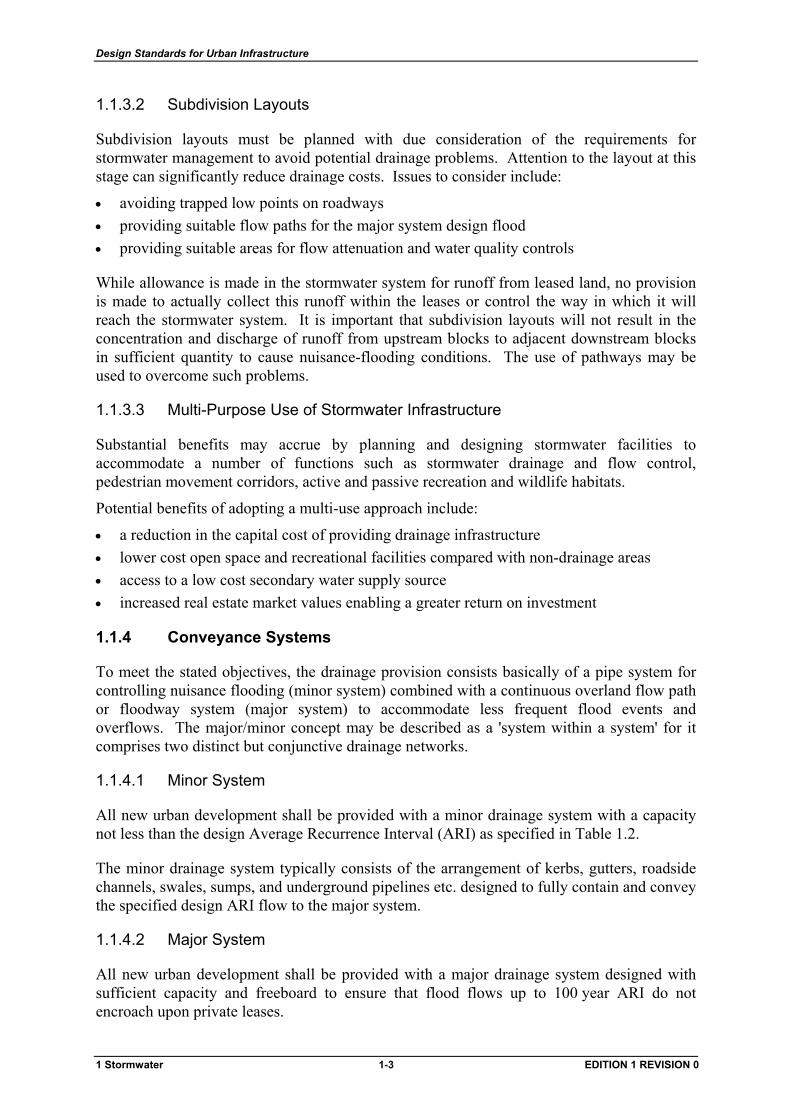
1.1.3.2 Subdivision Layouts
Subdivision layouts must be planned with due consideration of the requirements for stormwater management to avoid potential drainage problems. Attention to the layout at this stage can significantly reduce drainage costs. Issues to consider include:
• avoiding trapped low points on roadways • providing suitable flow paths for the major system design flood • providing suitable areas for flow attenuation and water quality controls
While allowance is made in the stormwater system for runoff from leased land, no provision is made to actually collect this runoff within the leases or control the way in which it will reach the stormwater system. It is important that subdivision layouts will not result in the concentration and discharge of runoff from upstream blocks to adjacent downstream blocks in sufficient quantity to cause nuisance-flooding conditions. The use of pathways may be used to overcome such problems.
1.1.3.3 Multi-Purpose Use of Stormwater Infrastructure
Substantial benefits may accrue by planning and designing stormwater facilities to accommodate a number of functions such as stormwater drainage and flow control, pedestrian movement corridors, active and passive recreation and wildlife habitats.
Potential benefits of adopting a multi-use approach include:
• a reduction in the capital cost of providing drainage infrastructure • lower cost open space and recreational facilities compared with non-drainage areas • access to a low cost secondary water supply source • increased real estate market values enabling a greater return on investment
1.1.4 Conveyance Systems
To meet the stated objectives, the drainage provision consists basically of a pipe system for controlling nuisance flooding (minor system) combined with a continuous overland flow path or floodway system (major system) to accommodate less frequent flood events and overflows. The major/minor concept may be described as a 'system within a system' for it comprises two distinct but conjunctive drainage networks.
1.1.4.1 Minor System
All new urban development shall be provided with a minor drainage system with a capacity not less than the design Average Recurrence Interval (ARI) as specified in Table 1.2.
The minor drainage system typically consists of the arrangement of kerbs, gutters, roadside channels, swales, sumps, and underground pipelines etc. designed to fully contain and convey the specified design ARI flow to the major system.
1.1.4.2 Major System
All new urban development shall be provided with a major drainage system designed with sufficient capacity and freeboard to ensure that flood flows up to 100 year ARI do not encroach upon private leases.
1 Stormwater 1-3 EDITION 1 REVISION 0
Design Standards for Urban Infrastructure
The major drainage system typically consists of the arrangement of pavements, roadway reserves, engineered waterways, retarding basins, and major cut-off drains etc. planned to convey a design flow of 100-year ARI in conjunction with the minor drainage system.
To provide this level of flood protection for existing leases or redevelopment sites in existing urban areas, it may be necessary to increase the size of the minor drainage system, set minimum building floor levels and provide levees or other flood protection measures.
1.1.4.3 Provision for Failure
It is important to ensure that the combined major/minor system can cope with surcharge due to blockages and flows in excess of the design ARI. If failure of cut-off drains, retarding basins, or pipe system and floodway structures occurs during these periods, the risk to life and property could be significantly increased.
In establishing the layout of the pipe network, Designers shall ensure that surcharge flows will not discharge onto leased property during flows up to and including 100 year ARI. For flows in excess of 100 year ARI, Designers shall ensure that the likelihood of nuisance flooding or damage to leased properties is minimised.
1.1.4.4 Natural Drainage Paths
The minor and major drainage systems shall be planned and designed so as to generally conform to natural drainage patterns and discharge to natural drainage paths in the catchment. These natural drainage paths should be modified as required to accept the higher peak flows resulting from urban development. However, the minor drainage system may be modified to conform to road and lease layouts.
Runoff must be discharged from a development in a manner that will not cause adverse impacts on downstream leases or stormwater systems. In general, runoff from development sites within a catchment shall be discharged at the existing natural drainage outlet or outlets. If the Designer wishes to change discharge points, he or she must demonstrate that the change will not have any adverse impacts on downstream leases or stormwater systems.
1.1.4.5 Surface Flow Criteria
Within a catchment, a range of surface flow criteria must be applied to minimise both nuisance flooding and major hazards from flooding of roadways, buildings, and other areas that have regular public access. The criteria apply to both major and minor flows and are provided in Table 1.15 for roads and Table 1.31 for engineered waterways.
1.1.4.6 Lease Drainage
In new development, each lease shall be individually serviced with a single service tie from the minor system pipe network to provide for the connection of drainage from buildings. However, on redevelopment sites, if the provision of a single tie will not service the entire lease or is considered impractical, the Operating Authority may upon written application, permit additional service ties to be provided.
1 Stormwater 1-4 EDITION 1 REVISION 0

Design Standards for Urban Infrastructure
In some cases, such as blocks in a cul-de-sac or for 'preserved environmental areas', specific approval may be given for drainage to be connected to a road gutter or directed to an overland drainage path rather than to the minor system pipe network.
1.1.5 Runoff Quantity Control
The level of runoff control required is dependent on the type of development proposed. Flow control requirements are stipulated for the following categories:
• new development • redevelopment of existing sites • augmentation of existing stormwater systems
Runoff control requirements for the above categories are summarised in Table 1.1.
Table 1.1 Flow Control Criteria
Category Minimum Standard
New Development Peak flow ≤ pre-development peak flow for minor and major system design ARI of new development
Redevelopment Peak flow ≤ pre-redevelopment peak flow for minor and major system design ARI of existing development
Stormwater System Augmentation
Surface flow criteria limits as specified in Table 1.15
No inundation of leases from overland flows up to and including the major system design ARI
1.1.5.1 New Development
New development is defined as the conversion of natural or rural areas into residential, commercial or industrial development.
For new development proposals, the post-development peak flow from the outlet point(s) of the site to the downstream public drainage system or receiving water shall not exceed the pre-development flow for both the minor and major system design storm ARI. Pre-development peak flow shall be the estimated flow from the site based on known or estimated catchment conditions prior to the new development.
To reduce peak outflows, the stormwater system may be provided with flow attenuation measures such as retarding basins, floodway storage, or active storage within urban lakes and water quality control ponds.
Design storm ARIs for the minor and major drainage systems shall be selected in accordance with Section 1.2.2.
1 Stormwater 1-5 EDITION 1 REVISION 0

Design Standards for Urban Infrastructure
1.1.5.2 Redevelopment
Redevelopment includes lease redevelopment and subdivision redevelopment. Lease redevelopment is defined as the redevelopment of single leases or multiple adjacent leases where all of the stormwater system will be privately owned. This covers both Unit and Dual Occupancy developments. Subdivision redevelopment is defined as redevelopment where all or part of the stormwater system will be handed over to the ACT Government and will become part of the public drainage system.
For redevelopment sites, the post-redevelopment peak flow from the outlet point(s) of the redevelopment site to the existing downstream public drainage system or receiving water shall not exceed the pre-redevelopment flow for both the minor and major system ARI. The pre-redevelopment peak flow shall be the estimated flow from the site based on the development conditions (including any existing flow attenuation facilities) prior to redevelopment.
The degree of runoff control required will depend on the scale of the development and the net change in impervious area. Flow control will be required for any redevelopment where the density (measured as the total equivalent impervious area) of the redevelopment is greater than that of the existing development.
The minimum responsibility of the Developer is to ensure that the redevelopment does not create or worsen any capacity problems in the existing public drainage system. This will generally require the construction of on-site and/or off-site public detention/retention systems.
The minor and major system design storm ARIs referred to shall be those appropriate for the existing development in accordance with Section 1.2.2. Note that these are the ARIs that the existing public drainage system should have been designed for, not the as-constructed capacity of the system.
1.1.5.3 Stormwater System Augmentation
Stormwater system augmentations are undertaken in existing urban catchments to alleviate flood hazards due to under-capacity minor and/or major drainage systems. In some older areas of Canberra, a formal major drainage system has not been provided. The main objectives for such augmentation works are to improve flood protection for leases and to increase pedestrian safety and vehicle stability on roadways.
The potential to increase the flow carrying capacity of existing roadways is usually limited and it therefore may be necessary to increase the ARI capacity of the minor drainage system above that specified in Table 1.2 in order to ensure that:
• the 100 year ARI ‘gap’ flow on roads (refer to Section 1.7.11) meets the surface flow criteria limits specified in Table 1.15
• overland flow from storms up to and including the 100 year ARI is not discharged through leases on the low side of road verges, particularly at steep ’T’ intersections and trapped road low points
1 Stormwater 1-6 EDITION 1 REVISION 0
Design Standards for Urban Infrastructure
1.1.6 Runoff Quality Control
1.1.6.1 General Strategy
Urban development will generally result in an increased level of export of a wide range of non-point source pollutants. To protect the quality of local streams, lakes, and river systems, a number of water quality control strategies have been adopted as follows;
• the establishment of urban lakes, primarily as biological treatment systems • the utilisation of water quality control ponds (WQCP) and wetlands, as physical and
biological treatment systems, upstream of urban lakes • the incorporation of gross pollutant traps (GPT) on inlets to urban lakes and WQCPs to
intercept trash and debris and the coarser fractions of sediment • the incorporation of 'off-stream' sediment interception ponds (SIP) in land development
works to intercept and chemically treat runoff prior to its discharge to the stormwater system
Additionally, the ACT Water Pollution Act was enacted in 1984 to control discharges to lakes, streams, and stormwater systems.
1.1.7 Ecological Considerations
1.1.7.1 Aesthetics
The stormwater drainage system shall be designed to enhance the appearance of the area and to maximise its use by the community.
1.1.7.2 Landscaping
The following landscape requirements are intended to ensure that the stormwater drainage system will enhance an area while ensuring that tree planting does not result in flood or tree root intrusion problems.
Tree planting should be restricted within 3 m of a stormwater pipeline except in the case of tree planting in street verges. Vigorous rooting tree species (eg. poplar, willow, or elm) shall not be planted within 10 m of a stormwater pipeline. Where a pipeline passes near or under existing mature trees, consideration shall be given to the use of an alternative alignment.
Allowance shall be made for the effects of landscaping in the hydraulic calculations of floodways and engineered waterways. Approval from the Operating Authority is required for the design factors used.
To minimise ongoing maintenance;
• no trees other than those with clean boles, strong crown structure, and no propensity for root suckering may be planted in the floodplain
• minimum spacing of trees shall be 3 m • maintenance free 'thicket' zones used for hydraulic reasons shall have a minimum 3 m
clearance from lease boundaries to provide access for mowing • no vegetation other than grass shall be planted within 3 m of a stormwater pipeline,
structure or concrete floodway invert
1 Stormwater 1-7 EDITION 1 REVISION 0
Design Standards for Urban Infrastructure
1.1.7.3 Water Abstraction
At present there are no regulations to control the use of the stormwater system with the exception of discharge of pollutants and environmental protection requirements. A licence to abstract water from lakes, ponds and the stormwater system is required under the Water Resources Act 1998. This licence is also required to meet the Environment ACT ‘Environmental Flow Guidelines’ that came into statutory effect from December 1999.
ACTCODE allows the use of stormwater harvesting on leases for irrigation and other second class water uses to provide for the conservation of potable water.
1.1.8 Maintenance
The stormwater drainage system shall be designed to be readily and economically maintained by the Operating Authority’s maintenance service provider and shall incorporate adequate access for maintenance machinery.
Any design incorporating the need for special or unusual equipment should not be prepared without the prior written approval of the Operating Authority. This approval also extends to the use of special techniques or the hire of special equipment.
The Designer shall refer to the Operating Authority for specific maintenance requirements for situations not covered by this document.
1.2 Hydrology
1.2.1 Design Principles
It is desirable that the ACT stormwater system be designed using methods and data which will result in a system of which all the unit parts are compatible. Design methods and data for urban drainage for Canberra shall be taken from the latest edition of Australian Rainfall and Runoff unless otherwise required by this document.
This document does not cover environmental flow hydrology. The requirements for environmental flows in the ACT are covered by Environment ACT’s ‘Environmental Flow Guidelines’ document.
For catchment areas greater than 50 hectares, two recognised flow estimation methods shall be used for comparative purposes.
1.2.2 Design Average Recurrence Intervals
The ACT stormwater system is designed on the basis that the cost/benefit of providing a certain standard of flood protection varies with the type of development.
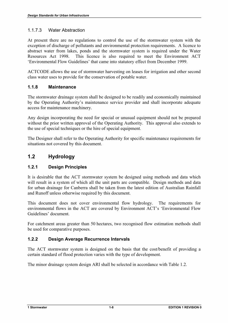
The minor drainage system design ARI shall be selected in accordance with Table 1.2.
1 Stormwater 1-8 EDITION 1 REVISION 0
Design Standards for Urban Infrastructure
Table 1.2 Minor System Design ARI
Type of Development ARI (Yrs)
Parliamentary Area (bounded by Lake Burley Griffin, Flynn Drive, State Circle (including Capital Hill), Brisbane Avenue & Bowen Park)
20
Town Centres (eg. Civic, Woden, Belconnen, Gungahlin and Tuggeranong)
20
Group and Neighbourhood Shopping Centres (eg. Pearce, Mawson, Torrens, Kippax and Kingston)
10
Industrial areas (eg. Fyshwick, Mitchell and Hume)
10
Service Trades areas (eg. Belconnen and Phillip)
10
Urban Neighbourhood development (except in designated preserved environment areas)
5
The major drainage system shall be designed to ensure that all leased land is protected against inundation from flood flows up to and including 100 year ARI.
The design analysis carried out by the Designer shall take into account the possibility of property damage or danger to life that might occur in specific situations. The design storm ARI recommended or adopted in such cases shall be the subject of specific advice and reports from the Designer to the Operating Authority. For example, the design ARI for cycleways and bridges should be consistent with AUSROADS bridge codes and ‘Guide to Traffic Engineering Practice – Bicycles’.
1.2.3 Impervious Area Assumptions
1.2.3.1 Leases
When estimating the design flow contribution from individual leases, due allowance should be made for possible future lease improvements and/or urban consolidation.
For single residential leases, the total impervious area selected for drainage design shall be based on the maximum permissible building plot ratio for the development type plus 10% of the total lease area to allow for driveways, carports, surface paving etc.
For all other development types, the total impervious area values provided in Table 1.3 may be adopted.
1 Stormwater 1-9 EDITION 1 REVISION 0
Design Standards for Urban Infrastructure
1.2.3.2 Composite Areas
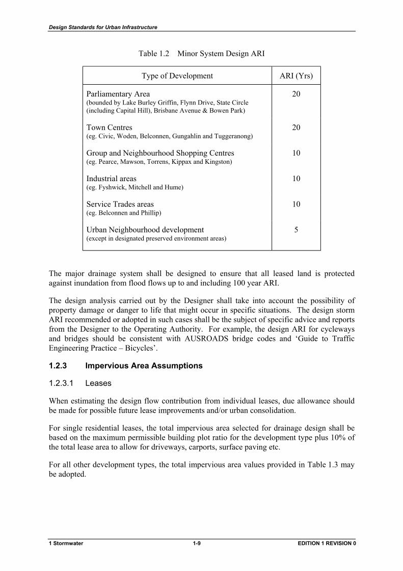
For larger-scale modelling of urban catchments, sub-catchments are typically composite areas that include leases, road reserves and open space areas etc. Table 1.3 provides typical total impervious area percentages that may be adopted for composite areas.
The Designer shall assess whether the adoption of typical values is accurate enough for the purposes of the drainage analysis. This may be sufficient for preliminary design or master planning, however, a more accurate assessment of total impervious area may be necessary for the investigation of stormwater system failures or detailed design.
Table 1.3 Composite Impervious Area Guidelines
Type of Development Design Impervious Area (%)
Single Residential 45
Multi-Units 60
Commercial and Service Trades 70
Group and Neighbourhood Shopping Centres
80
Town Centres 90
Industrial 90
1.2.4 Rational Method
The following procedures shall be adopted when using the Rational Method for drainage design in urban catchments in the ACT.
The recommended procedures for the Rational Method have been determined from calibration against gauged flood frequency curves derived for catchments in Giralang and Mawson. Rational Method procedures from the latest edition of Australian Rainfall and Runoff shall not be used unless otherwise directed by the Operating Authority.
Partial area effects shall be taken into account in determining peak flow rates.
1.2.4.1 Time of Concentration
The minimum time of concentration to be considered shall be 5 minutes.
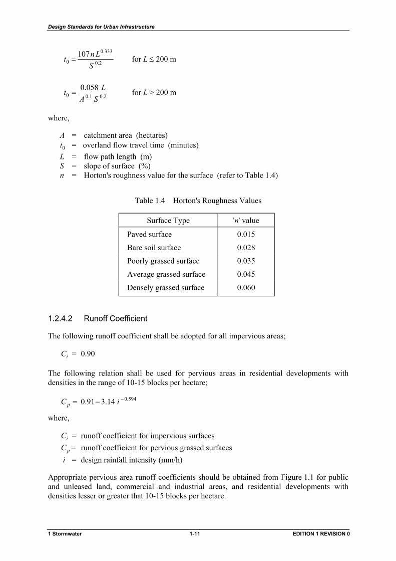
The following relations shall be used for determining the overland flow travel time component ( t ) of the total surface flow time of concentration (t0 c) for catchments in the ACT;
1 Stormwater 1-10 EDITION 1 REVISION 0
Design Standards for Urban Infrastructure
2.0
333.0
0107
SLnt = for L ≤ 200 m
2.01.00058.0
SALt = for L > 200 m
where,
A = catchment area (hectares) 0t = overland flow travel time (minutes)
L = flow path length (m) S = slope of surface (%) n = Horton's roughness value for the surface (refer to Table 1.4)
Table 1.4 Horton's Roughness Values
Surface Type 'n' value
Paved surface 0.015
Bare soil surface 0.028
Poorly grassed surface 0.035
Average grassed surface 0.045
Densely grassed surface 0.060
1.2.4.2 Runoff Coefficient
The following runoff coefficient shall be adopted for all impervious areas;
iC = 0.90
The following relation shall be used for pervious areas in residential developments with densities in the range of 10-15 blocks per hectare;
594.014.391.0 −−= iC p
where,
iC = runoff coefficient for impervious surfaces
pC = runoff coefficient for pervious grassed surfaces i = design rainfall intensity (mm/h)
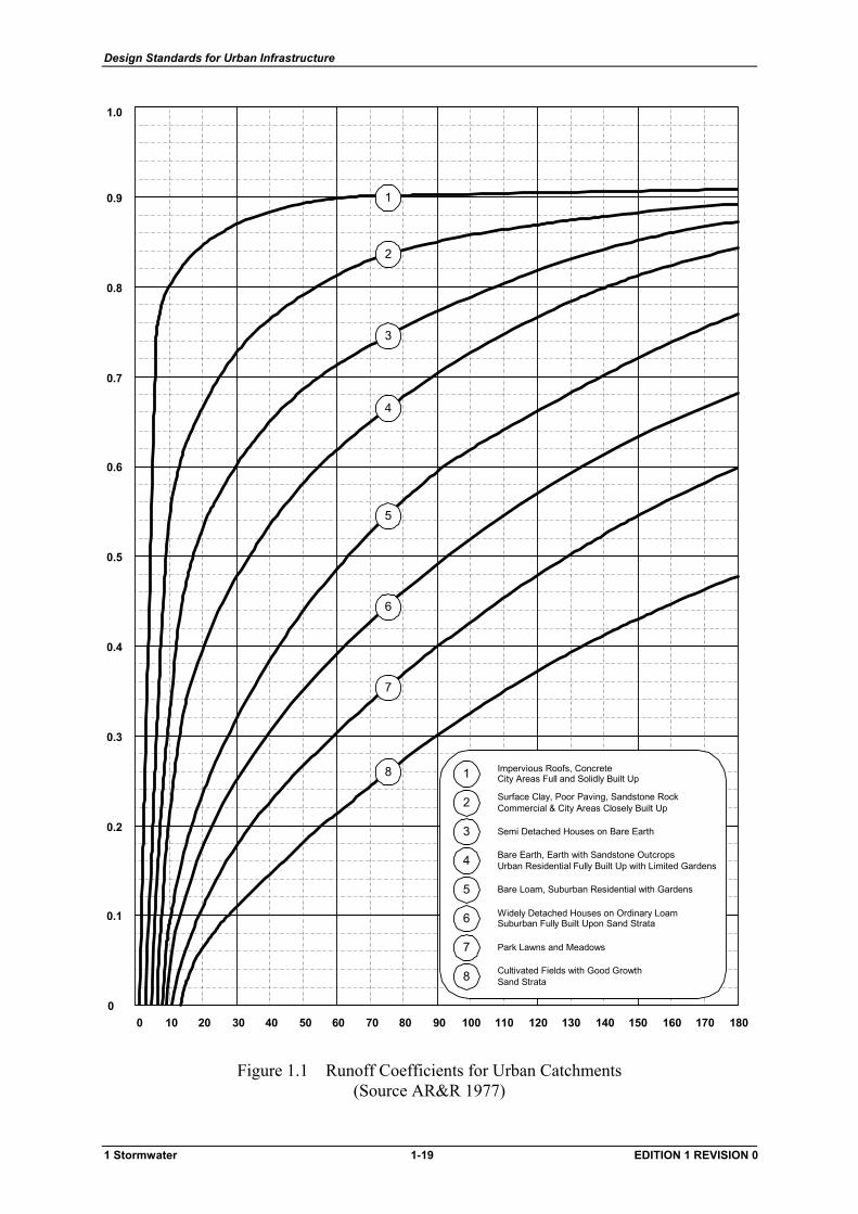
Appropriate pervious area runoff coefficients should be obtained from Figure 1.1 for public and unleased land, commercial and industrial areas, and residential developments with densities lesser or greater that 10-15 blocks per hectare.
1 Stormwater 1-11 EDITION 1 REVISION 0
Design Standards for Urban Infrastructure
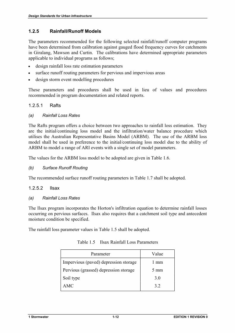
1.2.5 Rainfall/Runoff Models
The parameters recommended for the following selected rainfall/runoff computer programs have been determined from calibration against gauged flood frequency curves for catchments in Giralang, Mawson and Curtin. The calibrations have determined appropriate parameters applicable to individual programs as follows;
• design rainfall loss rate estimation parameters • surface runoff routing parameters for pervious and impervious areas • design storm event modelling procedures
These parameters and procedures shall be used in lieu of values and procedures recommended in program documentation and related reports.
1.2.5.1 Rafts
(a) Rainfall Loss Rates
The Rafts program offers a choice between two approaches to rainfall loss estimation. They are the initial/continuing loss model and the infiltration/water balance procedure which utilises the Australian Representative Basins Model (ARBM). The use of the ARBM loss model shall be used in preference to the initial/continuing loss model due to the ability of ARBM to model a range of ARI events with a single set of model parameters.
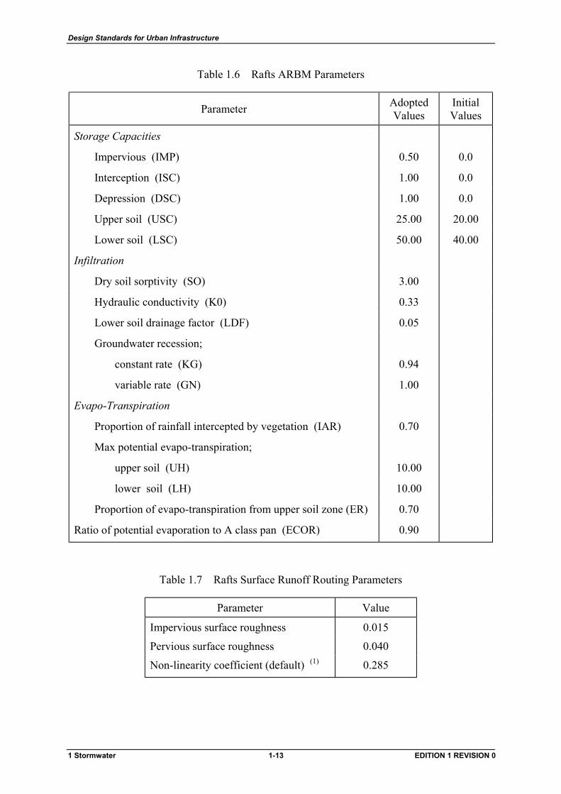
The values for the ARBM loss model to be adopted are given in Table 1.6.
(b) Surface Runoff Routing
The recommended surface runoff routing parameters in Table 1.7 shall be adopted.
1.2.5.2 Ilsax
(a) Rainfall Loss Rates
The Ilsax program incorporates the Horton's infiltration equation to determine rainfall losses occurring on pervious surfaces. Ilsax also requires that a catchment soil type and antecedent moisture condition be specified.
The rainfall loss parameter values in Table 1.5 shall be adopted.
Table 1.5 Ilsax Rainfall Loss Parameters
Parameter Value
Impervious (paved) depression storage 1 mm
Pervious (grassed) depression storage 5 mm
Soil type 3.0
AMC 3.2
1 Stormwater 1-12 EDITION 1 REVISION 0
Design Standards for Urban Infrastructure
Table 1.6 Rafts ARBM Parameters
Parameter Adopted Values
Initial Values
Storage Capacities
Impervious (IMP) 0.50 0.0
Interception (ISC) 1.00 0.0
Depression (DSC) 1.00 0.0
Upper soil (USC) 25.00 20.00
Lower soil (LSC) 50.00 40.00
Infiltration
Dry soil sorptivity (SO) 3.00
Hydraulic conductivity (K0) 0.33
Lower soil drainage factor (LDF) 0.05
Groundwater recession;
constant rate (KG) 0.94
variable rate (GN) 1.00
Evapo-Transpiration
Proportion of rainfall intercepted by vegetation (IAR) 0.70
Max potential evapo-transpiration;
upper soil (UH) 10.00
lower soil (LH) 10.00
Proportion of evapo-transpiration from upper soil zone (ER) 0.70
Ratio of potential evaporation to A class pan (ECOR) 0.90
Table 1.7 Rafts Surface Runoff Routing Parameters
Parameter Value
Impervious surface roughness 0.015
Pervious surface roughness 0.040
Non-linearity coefficient (default) (1) 0.285
1 Stormwater 1-13 EDITION 1 REVISION 0
Design Standards for Urban Infrastructure
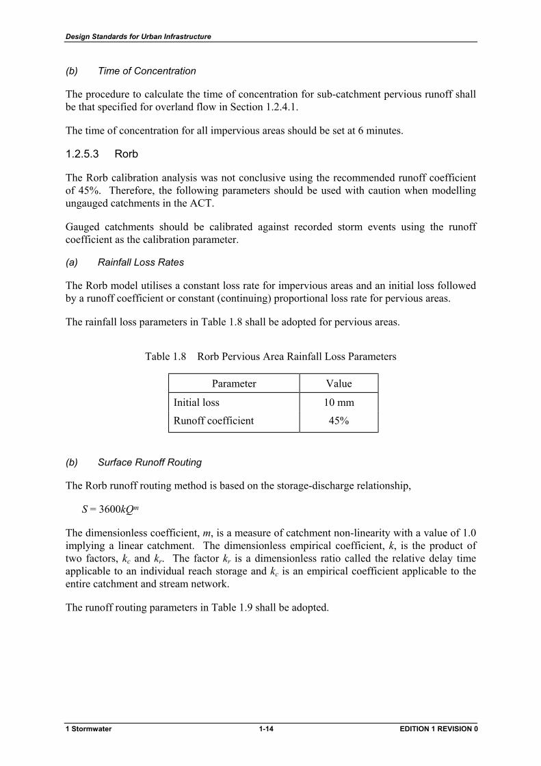
(b) Time of Concentration
The procedure to calculate the time of concentration for sub-catchment pervious runoff shall be that specified for overland flow in Section 1.2.4.1.
The time of concentration for all impervious areas should be set at 6 minutes.
1.2.5.3 Rorb
The Rorb calibration analysis was not conclusive using the recommended runoff coefficient of 45%. Therefore, the following parameters should be used with caution when modelling ungauged catchments in the ACT.
Gauged catchments should be calibrated against recorded storm events using the runoff coefficient as the calibration parameter.
(a) Rainfall Loss Rates
The Rorb model utilises a constant loss rate for impervious areas and an initial loss followed by a runoff coefficient or constant (continuing) proportional loss rate for pervious areas.
The rainfall loss parameters in Table 1.8 shall be adopted for pervious areas.
Table 1.8 Rorb Pervious Area Rainfall Loss Parameters
Parameter Value
Initial loss 10 mm
Runoff coefficient 45%
(b) Surface Runoff Routing
The Rorb runoff routing method is based on the storage-discharge relationship,
S = 3600kQm
The dimensionless coefficient, m, is a measure of catchment non-linearity with a value of 1.0 implying a linear catchment. The dimensionless empirical coefficient, k, is the product of two factors, kc and kr. The factor kr is a dimensionless ratio called the relative delay time applicable to an individual reach storage and kc is an empirical coefficient applicable to the entire catchment and stream network.
The runoff routing parameters in Table 1.9 shall be adopted.
1 Stormwater 1-14 EDITION 1 REVISION 0
Design Standards for Urban Infrastructure
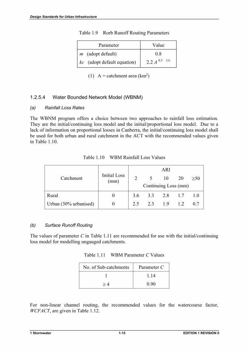
Table 1.9 Rorb Runoff Routing Parameters
Parameter Value
m (adopt default) 0.8
kc (adopt default equation) 2.2 A 0.5 (1)
(1) A = catchment area (km2)
1.2.5.4 Water Bounded Network Model (WBNM)
(a) Rainfall Loss Rates
The WBNM program offers a choice between two approaches to rainfall loss estimation. They are the initial/continuing loss model and the initial/proportional loss model. Due to a lack of information on proportional losses in Canberra, the initial/continuing loss model shall be used for both urban and rural catchment in the ACT with the recommended values given in Table 1.10.
Table 1.10 WBM Rainfall Loss Values
ARI
2 5 10 20 ≥50 Catchment Initial Loss (mm)
Continuing Loss (mm)
Rural 0 3.6 3.3 2.8 1.7 1.0
Urban (30% urbanised) 0 2.5 2.3 1.9 1.2 0.7
(b) Surface Runoff Routing
The values of parameter C in Table 1.11 are recommended for use with the initial/continuing loss model for modelling ungauged catchments.
Table 1.11 WBM Parameter C Values
No. of Sub-catchments Parameter C
1 1.14
≥ 4 0.90
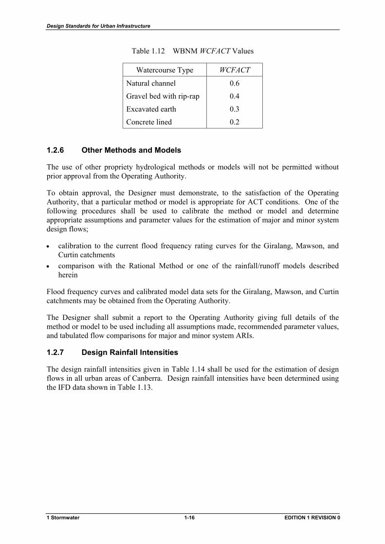
For non-linear channel routing, the recommended values for the watercourse factor, WCFACT, are given in Table 1.12.
1 Stormwater 1-15 EDITION 1 REVISION 0
Design Standards for Urban Infrastructure
Table 1.12 WBNM WCFACT Values
Watercourse Type WCFACT
Natural channel 0.6
Gravel bed with rip-rap 0.4
Excavated earth 0.3
Concrete lined 0.2
1.2.6 Other Methods and Models
The use of other propriety hydrological methods or models will not be permitted without prior approval from the Operating Authority.
To obtain approval, the Designer must demonstrate, to the satisfaction of the Operating Authority, that a particular method or model is appropriate for ACT conditions. One of the following procedures shall be used to calibrate the method or model and determine appropriate assumptions and parameter values for the estimation of major and minor system design flows;
• calibration to the current flood frequency rating curves for the Giralang, Mawson, and Curtin catchments
• comparison with the Rational Method or one of the rainfall/runoff models described herein
Flood frequency curves and calibrated model data sets for the Giralang, Mawson, and Curtin catchments may be obtained from the Operating Authority.
The Designer shall submit a report to the Operating Authority giving full details of the method or model to be used including all assumptions made, recommended parameter values, and tabulated flow comparisons for major and minor system ARIs.
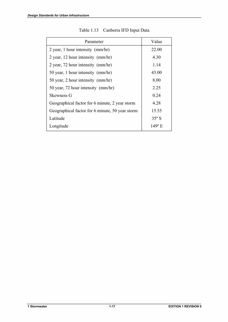
1.2.7 Design Rainfall Intensities
The design rainfall intensities given in Table 1.14 shall be used for the estimation of design flows in all urban areas of Canberra. Design rainfall intensities have been determined using the IFD data shown in Table 1.13.
1 Stormwater 1-16 EDITION 1 REVISION 0
Design Standards for Urban Infrastructure
Table 1.13 Canberra IFD Input Data
Parameter Value
2 year, 1 hour intensity (mm/hr) 22.00
2 year, 12 hour intensity (mm/hr) 4.30
2 year, 72 hour intensity (mm/hr) 1.14
50 year, 1 hour intensity (mm/hr) 43.00
50 year, 2 hour intensity (mm/hr) 8.00
50 year, 72 hour intensity (mm/hr) 2.25
Skewness G 0.24
Geographical factor for 6 minute, 2 year storm 4.28
Geographical factor for 6 minute, 50 year storm 15.55
Latitude 35º S
Longitude 149º E
1 Stormwater 1-17 EDITION 1 REVISION 0

Design Standards for Urban Infrastructure
Table 1.14 Canberra Design Rainfall Intensities (mm/hr)
Average Recurrence Interval (years) Duration
1 2 5 10 20 50 100
5m 55 73 98 115 138 169 194 6 51 68 92 107 128 157 180 7 48.5 64 86 101 120 147 169 8 46.0 61 82 95 113 139 159 9 43.9 58 78 91 108 132 151 10 42.0 55 74 86 103 125 143 11 40.3 53 71 83 98 120 137 12 38.7 51 68 79 94 115 131 13 37.4 49.1 66 76 90 110 126 14 36.1 47.5 63 74 87 106 121 15 35.0 45.9 61 71 84 102 117 16 33.9 44.5 59 69 81 99 113 17 32.9 43.2 58 67 79 96 109 18 32.0 42.0 56 65 77 93 106 20 30.4 39.9 53 61 72 88 100 25 27.1 35.5 46.9 54 64 77 88 30 24.6 32.2 42.4 48.9 58 70 79 35 22.6 29.6 38.8 44.7 53 63 72 40 21.0 27.4 35.9 41.3 48.5 58 66 45 19.7 25.6 33.5 38.5 45.1 54 62 50 18.5 24.1 31.4 36.1 42.2 51 58 55 17.5 22.8 29.7 34.0 39.8 47.8 54 60 16.7 21.7 28.1 32.2 37.7 45.2 51 75 14.5 18.8 24.4 27.9 32.6 39.0 44.1 90 12.9 16.7 21.6 24.7 28.9 34.6 39.1
2.0h 10.7 13.9 17.9 20.4 23.8 28.5 32.2 3.0 8.18 10.6 13.6 15.5 18.1 21.6 24.4 4.0 6.77 8.76 11.2 12.8 14.9 17.7 20.0 5.0 5.84 7.56 9.68 11.0 12.8 15.2 17.1 6.0 5.18 6.70 8.57 9.72 11.3 13.4 15.1 8.0 4.29 5.54 7.07 8.01 9.29 11.0 12.4
10.0 3.70 4.78 6.09 6.90 7.99 9.48 10.7 12.0 3.29 4.24 5.39 6.10 7.06 8.37 9.41 14.0 2.95 3.81 4.85 5.50 6.37 7.56 8.50 16.0 2.69 3.47 4.43 5.02 5.83 6.92 7.79 18.0 2.47 3.20 4.09 4.64 5.38 6.40 7.20 20.0 2.30 2.97 3.80 4.32 5.01 5.96 6.72 22.0 2.15 2.77 3.56 4.04 4.70 5.59 6.30 24.0 2.02 2.61 3.35 3.81 4.43 5.28 5.95 36.0 1.50 1.94 2.51 2.86 3.34 3.99 4.50 48.0 1.20 1.56 2.02 2.31 2.70 3.24 3.66 60.0 1.00 1.31 1.70 1.95 2.28 2.73 3.10 72.0 0.86 1.12 1.46 1.68 1.97 2.36 2.68
1 Stormwater 1-18 EDITION 1 REVISION 0
Design Standards for Urban Infrastructure
0 10 20 30 40 50 60 70 80 90 100 110 120 130 140 150 160 170 180
1.0
0.9
0.8
0.7
0.6
0.5
0.4
0.3
0.2
0.1
0
1
3
2
4
5
6
7
8 1
3
2
4
5
6
7
8
Semi Detached Houses on Bare Earth
Bare Loam, Suburban Residential with Gardens
Park Lawns and Meadows
Impervious Roofs, ConcreteCity Areas Full and Solidly Built Up
Surface Clay, Poor Paving, Sandstone RockCommercial & City Areas Closely Built Up
Urban Residential Fully Built Up with Limited GardensBare Earth, Earth with Sandstone Outcrops
Widely Detached Houses on Ordinary LoamSuburban Fully Built Upon Sand Strata
Cultivated Fields with Good GrowthSand Strata
Figure 1.1 Runoff Coefficients for Urban Catchments (Source AR&R 1977)
1 Stormwater 1-19 EDITION 1 REVISION 0
Design Standards for Urban Infrastructure
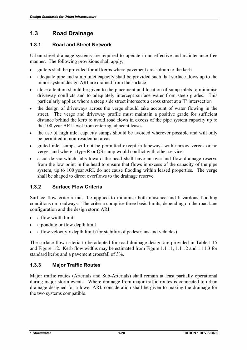
1.3 Road Drainage
1.3.1 Road and Street Network
Urban street drainage systems are required to operate in an effective and maintenance free manner. The following provisions shall apply;
• gutters shall be provided for all kerbs where pavement areas drain to the kerb • adequate pipe and sump inlet capacity shall be provided such that surface flows up to the
minor system design ARI are drained from the surface • close attention should be given to the placement and location of sump inlets to minimise
driveway conflicts and to adequately intercept surface water from steep grades. This particularly applies where a steep side street intersects a cross street at a 'T' intersection
• the design of driveways across the verge should take account of water flowing in the street. The verge and driveway profile must maintain a positive grade for sufficient distance behind the kerb to avoid road flows in excess of the pipe system capacity up to the 100 year ARI level from entering adjacent leases
• the use of high inlet capacity sumps should be avoided wherever possible and will only be permitted in non-residential areas
• grated inlet sumps will not be permitted except in laneways with narrow verges or no verges and where a type R or QS sump would conflict with other services
• a cul-de-sac which falls toward the head shall have an overland flow drainage reserve from the low point in the head to ensure that flows in excess of the capacity of the pipe system, up to 100 year ARI, do not cause flooding within leased properties. The verge shall be shaped to direct overflows to the drainage reserve
1.3.2 Surface Flow Criteria
Surface flow criteria must be applied to minimise both nuisance and hazardous flooding conditions on roadways. The criteria comprise three basic limits, depending on the road lane configuration and the design storm ARI:
• a flow width limit • a ponding or flow depth limit • a flow velocity x depth limit (for stability of pedestrians and vehicles)
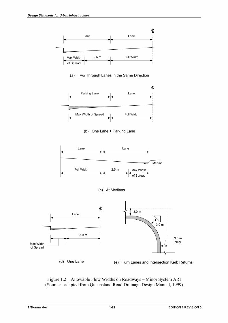
The surface flow criteria to be adopted for road drainage design are provided in Table 1.15 and Figure 1.2. Kerb flow widths may be estimated from Figure 1.11.1, 1.11.2 and 1.11.3 for standard kerbs and a pavement crossfall of 3%.
1.3.3 Major Traffic Routes
Major traffic routes (Arterials and Sub-Arterials) shall remain at least partially operational during major storm events. Where drainage from major traffic routes is connected to urban drainage designed for a lower ARI, consideration shall be given to making the drainage for the two systems compatible.
1 Stormwater 1-20 EDITION 1 REVISION 0

Design Standards for Urban Infrastructure
1.3.3.1 Major Drainage Crossings
Crossings (eg. bridges, culverts, etc) over major floodways and natural waterways shall be designed in accordance with the AUSTROADS Bridge Design Code and the AUSTROADS Bridge Waterway Design Guidelines.
A minimum freeboard of 0.6 m shall be provided at the upstream face of the crossing to minimise potential damage from floating debris.
Table 1.15 Surface Flow Criteria for Roads (Source: adapted from Queensland Road Drainage Design Manual, 1999)
Criteria Surface Flow Limit
Minor System Flow
Two through lanes in the same direction
One full clear lane + minimum 2.5 m clear width in the other lane
One lane plus parking lane One full lane clear
One lane Minimum 3.0 m clear width in the lane
At medians Minimum 2.5 m clear width in the traffic lane
At turn lanes Minimum clear width of 3.0 m in the lane
At pedestrian crossings W ≤ 0.45 m (1 year ARI flow)
At intersection kerb returns Clear turning width of 3.0 m
50 year ARI Flow
Major Traffic Routes One full lane clear
Major System Flow
All locations D ≤ 50 mm above top of kerb
Pedestrian safety (a) no obvious danger (b) obvious danger
V.D < 0.6 m2/s V.D < 0.4 m2/s
Vehicular safety V.D < 0.6 m2/s
Notes:
(1) W = flow width on road from kerb gutter invert (2) flow width criteria applies to each direction of traffic flow (3) D = flow depth on road at kerb gutter invert (4) V = average longitudinal flow velocity (5) the flow affected area shall be taken as that where the flow depth is greater than 3 mm (6) lane includes acceleration or deceleration lanes > 60 km/h and any parking lane that has
the potential in the future to become used as a through lane for full or part time
1 Stormwater 1-21 EDITION 1 REVISION 0
Design Standards for Urban Infrastructure
3.0 m
3.0 m
3.0 mclear
(e) Turn Lanes and Intersection Kerb Returns
Lane
3.0 m
Max Widthof Spread
C
(d) One Lane
Lane Lane
2.5 mFull Width Max Width
of Spread
Median
(c) At Medians
(a) Two Through Lanes in the Same Direction
LaneLane
2.5 m Full WidthMax Width
of Spread
C
(b) One Lane + Parking Lane
LaneParking Lane
Max Width of Spread Full Width
C
Figure 1.2 Allowable Flow Widths on Roadways – Minor System ARI (Source: adapted from Queensland Road Drainage Design Manual, 1999)
1 Stormwater 1-22 EDITION 1 REVISION 0
Design Standards for Urban Infrastructure
1.3.3.2 Protection Drains
Carriageways in cuttings and cut batters should be adequately protected from runoff originating beyond the limits of the road. This protection will generally take the form of cut-off drains or dished gutters. The general requirements for cut-off drains as set out in Section 1.8 shall be observed for these protection drains.
1.3.3.3 Cross Drainage
Flows up to and including 100 year ARI shall not be permitted to flow onto major traffic routes from adjacent land.
1.3.4 Underpasses
Pedestrian underpasses on roadways shall be provided with sufficient longitudinal grade to facilitate free drainage wherever possible.
Where a self-draining underpass is not possible, the underpass drainage system shall be designed for a 20 year ARI capacity.
Public safety considerations preclude the use of grated sumps or grated strip drains in underpasses.
Where an underpass is part of an engineered waterway, the free draining underpass drainage system shall be designed for a 5 year ARI. The level of footpaths and cycleways shall be above the 2 year ARI flood level in the engineered waterway. A floodway advisory sign shall be provided on each approach to the underpass (refer to Section 1.7.7).
1.4 Pipelines
1.4.1 Materials
1.4.1.1 Pipe Types
Stormwater pipelines shall be constructed from materials proven to be structurally sound and durable and have satisfactory jointing systems. The use of two or more types of pipe material on a single length of pipeline is not acceptable.
Stormwater pipelines shall be constructed with;
• Fibre Reinforced Cement Pipes (FRC) • Steel reinforced Concrete Pipes (SRC) • Ductile Iron Cement Lined (DICL) • Unplasticised Polyvinyl Chloride Pipes (uPVC) • Vitrified Clay Pipes (VC) • Galvanised steel pipes (GS).
Alternative pipe materials may be acceptable. Proposals for the use of other materials shall be referred to the Operating Authority for consideration.
1 Stormwater 1-23 EDITION 1 REVISION 0
Design Standards for Urban Infrastructure
1.4.1.2 Pipe Design
FRC pipes shall comply with the latest edition of AS 4139.
SRC pipes shall comply with the latest editions of AS 4058 and AS 3725.
DICL pipes shall comply with the latest editions of AS 1631 and AS 2280.
uPVC pipes shall comply with the latest editions of AS 1260 and AS 2566. Pipes shall be solid walled, Class SN8 to AS 1260 except for 100 mm diameter which shall be Class SN6.
VC pipes shall comply with the latest editions of AS 1741 and AS 4060. All VC pipes shall be Class 4.
GS pipes shall comply with the latest editions of AS 1761.
1.4.1.3 Jointing
Pipes need to be capable of resisting root intrusion, hydraulic pressure and , soil loading, and preferably have some flexibility at joints.
Pipe jointing shall be as follows;
• 100 mm to 375 mm diameter pipes shall be rubber ring jointed, except for 100 mm uPVC pipes which shall be solvent welded
• 450 mm diameter and larger pipes shall be rubber ring jointed, or flush jointed with an external proprietary band (eg. Humes EB band, Rocla Sand or similar). However, pipes designed to operate under hydraulic conditions that exceed 2.0 m head shall have rubber ring joints
• 450 mm to 675 mm diameter pipes located under roadways shall have rubber ring joints
Locations of various joint types shall be shown on the design drawings.
The maximum allowable head for all pipes shall be in accordance with the appropriate Australian Standard.
1.4.2 Locations and Alignments
1.4.2.1 Roadway Reserves
Stormwater pipelines should be located on the high side of road reserves to permit relatively short service tie connections to adjacent properties.
The locations for stormwater pipelines are set out in Design Standard 4 – Road Verges.
Acceptable alignments shall be in accordance with Table 1.16.
Curved pipeline alignments are preferred on curved roadways. However, where there are significant advantages, eg culs-de-sac or narrow street verges, straight alignments may be permitted (refer to Section 1.4.10).
1 Stormwater 1-24 EDITION 1 REVISION 0
Design Standards for Urban Infrastructure
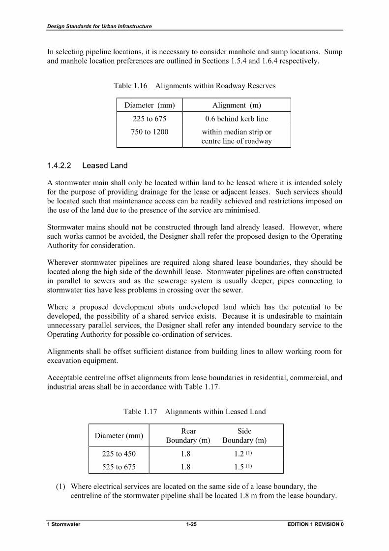
In selecting pipeline locations, it is necessary to consider manhole and sump locations. Sump and manhole location preferences are outlined in Sections 1.5.4 and 1.6.4 respectively.
Table 1.16 Alignments within Roadway Reserves
Diameter (mm) Alignment (m)
225 to 675 0.6 behind kerb line
750 to 1200 within median strip or centre line of roadway
1.4.2.2 Leased Land
A stormwater main shall only be located within land to be leased where it is intended solely for the purpose of providing drainage for the lease or adjacent leases. Such services should be located such that maintenance access can be readily achieved and restrictions imposed on the use of the land due to the presence of the service are minimised.
Stormwater mains should not be constructed through land already leased. However, where such works cannot be avoided, the Designer shall refer the proposed design to the Operating Authority for consideration.
Wherever stormwater pipelines are required along shared lease boundaries, they should be located along the high side of the downhill lease. Stormwater pipelines are often constructed in parallel to sewers and as the sewerage system is usually deeper, pipes connecting to stormwater ties have less problems in crossing over the sewer.
Where a proposed development abuts undeveloped land which has the potential to be developed, the possibility of a shared service exists. Because it is undesirable to maintain unnecessary parallel services, the Designer shall refer any intended boundary service to the Operating Authority for possible co-ordination of services.
Alignments shall be offset sufficient distance from building lines to allow working room for excavation equipment.
Acceptable centreline offset alignments from lease boundaries in residential, commercial, and industrial areas shall be in accordance with Table 1.17.
Table 1.17 Alignments within Leased Land
Diameter (mm) Rear Side Boundary (m) Boundary (m)
225 to 450 1.8 1.2 (1)
525 to 675 1.8 1.5 (1)
(1) Where electrical services are located on the same side of a lease boundary, the centreline of the stormwater pipeline shall be located 1.8 m from the lease boundary.
1 Stormwater 1-25 EDITION 1 REVISION 0
Design Standards for Urban Infrastructure
1.4.2.3 Unleased Land
The location of stormwater pipelines within unleased public land such as open space shall be brought to the attention of the Operating Authority for consideration. As a guide, unless directed otherwise, stormwater pipelines shall be located 5.2 m off the nearest lease boundary.
1.4.2.4 Clearance from Other Services
Minimum clearances have been established to reduce the likelihood of damage to stormwater pipelines or other services, and to protect personnel during construction or maintenance work.
Under no circumstances shall stormwater pipelines be;
• cranked to avoid other services or obstacles • located longitudinally directly above or below other underground services in the same
trench
Where a stormwater pipeline crosses or is constructed adjacent to an existing service, the design shall be based on the work-as-executed location and level of that service. The design documents shall direct the Contractor to verify the location and level of the existing service prior to constructing the stormwater pipeline in question.
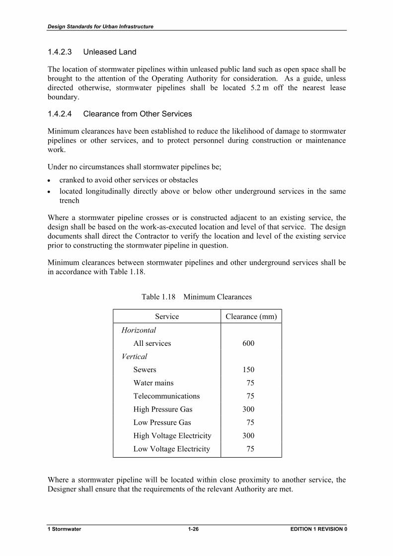
Minimum clearances between stormwater pipelines and other underground services shall be in accordance with Table 1.18.
Table 1.18 Minimum Clearances
Service Clearance (mm)
Horizontal
All services 600
Vertical
Sewers 150
Water mains 75
Telecommunications 75
High Pressure Gas 300
Low Pressure Gas 75
High Voltage Electricity 300
Low Voltage Electricity 75
Where a stormwater pipeline will be located within close proximity to another service, the Designer shall ensure that the requirements of the relevant Authority are met.
1 Stormwater 1-26 EDITION 1 REVISION 0

Design Standards for Urban Infrastructure
Stormwater pipelines shall be designed such that maintenance activities can be performed without the risk of inadvertent damage to the assets of other Authorities.
1.4.3 Drainage Easements
1.4.3.1 General
A drainage easement shall be wide enough to contain the service and provide working space on each side of the service for future maintenance activities.
Only pipelines up to and including 675 mm diameter may be located in easements within leased properties. Larger diameter pipelines shall be located outside leased properties in unleased open space or in separate drainage reserves.
In some developments, direct maintenance access to a stormwater main within a block may be difficult or prevented entirely. In such cases, easements and inter-allotment pipelines shall not terminate at a dead end but shall be extended to a point where access may be gained from a road reserve or other unleased area with direct access. A manhole shall be located on both ends of the pipeline to facilitate access.
Minimum drainage easement widths shall be in accordance with Table 1.19.
Table 1.19 Minimum Drainage Easement Widths
Easement Width (m) Diameter (mm)
Single Easement Common Easement
0 - 3.0 m deep
225 to 450 2.5 3.5
525 to 675 3.0 3.5
3.0 - 6.0 m deep
225 to 450 3.5 4.5
525 to 675 4.0 5.0
Note: Where electrical services are laid on the same side of the lease boundary, the required easement width shall be increased by 500 mm.
1.4.3.2 Common Easements
Common easements for stormwater and sewer pipelines are not desirable. Where common easements are unavoidable, the following requirements shall be used:
• The minimum easement width shall be 3.5 m • The stormwater or sewer pipe centrelines shall be located at 1.2 m and 2.4 m alignments
from the property boundary • Where possible, the deeper main should be located furthermost from the block boundary
1 Stormwater 1-27 EDITION 1 REVISION 0
Design Standards for Urban Infrastructure
• Where block boundaries form ‘kinks’, pipes alignments may have to be swapped to allow sufficient space for manholes and to ensure that such manholes are not located under the boundary fenceline
• Common trenching for both pipes is not acceptable. The deeper main should be laid first and backfilled prior to excavating the shallower main. The contractor should be made aware of this, preferably through a contract exception clause
1.4.4 Drainage Reserves
Pipelines 750 mm diameter and larger shall not be located within leased properties. These pipelines shall be located within unleased open space or a separate drainage reserve shall be provided.
Consideration should be given to the multi-purpose use of drainage reserves such as open space or pedestrian corridors.
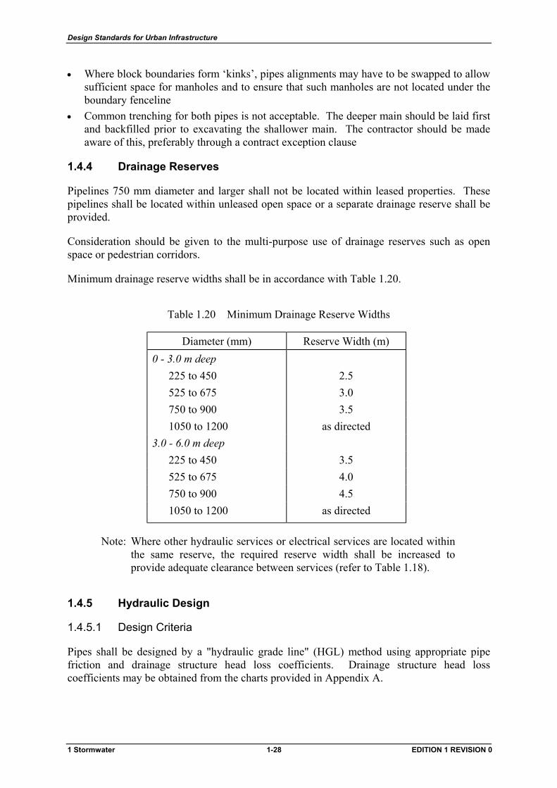
Minimum drainage reserve widths shall be in accordance with Table 1.20.
Table 1.20 Minimum Drainage Reserve Widths
Diameter (mm) Reserve Width (m) 0 - 3.0 m deep
225 to 450 2.5 525 to 675 3.0 750 to 900 3.5 1050 to 1200 as directed
3.0 - 6.0 m deep 225 to 450 3.5 525 to 675 4.0 750 to 900 4.5 1050 to 1200 as directed
Note: Where other hydraulic services or electrical services are located within the same reserve, the required reserve width shall be increased to provide adequate clearance between services (refer to Table 1.18).
1.4.5 Hydraulic Design
1.4.5.1 Design Criteria
Pipes shall be designed by a "hydraulic grade line" (HGL) method using appropriate pipe friction and drainage structure head loss coefficients. Drainage structure head loss coefficients may be obtained from the charts provided in Appendix A.
1 Stormwater 1-28 EDITION 1 REVISION 0
Design Standards for Urban Infrastructure
Actual pipe diameters, as opposed to nominal pipe diameters, shall be used for hydraulic calculations.
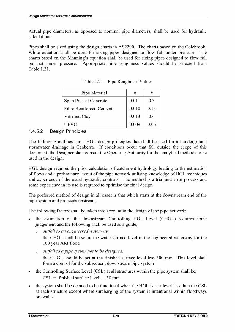
Pipes shall be sized using the design charts in AS2200. The charts based on the Colebrook-White equation shall be used for sizing pipes designed to flow full under pressure. The charts based on the Manning’s equation shall be used for sizing pipes designed to flow full but not under pressure. Appropriate pipe roughness values should be selected from Table 1.21.
Table 1.21 Pipe Roughness Values
Pipe Material n k
Spun Precast Concrete 0.011 0.3
Fibre Reinforced Cement 0.010 0.15
Vitrified Clay 0.013 0.6
UPVC 0.009 0.06 1.4.5.2 Design Principles
The following outlines some HGL design principles that shall be used for all underground stormwater drainage in Canberra. If conditions occur that fall outside the scope of this document, the Designer shall consult the Operating Authority for the analytical methods to be used in the design.
HGL design requires the prior calculation of catchment hydrology leading to the estimation of flows and a preliminary layout of the pipe network utilising knowledge of HGL techniques and experience of the usual hydraulic controls. The method is a trial and error process and some experience in its use is required to optimise the final design.
The preferred method of design in all cases is that which starts at the downstream end of the pipe system and proceeds upstream.
The following factors shall be taken into account in the design of the pipe network;
• the estimation of the downstream Controlling HGL Level (CHGL) requires some judgement and the following shall be used as a guide;
outfall to an engineered waterway,
the CHGL shall be set at the water surface level in the engineered waterway for the 100 year ARI flood
outfall to a pipe system yet to be designed, the CHGL should be set at the finished surface level less 300 mm. This level shall form a control for the subsequent downstream pipe system
• the Controlling Surface Level (CSL) at all structures within the pipe system shall be; CSL = finished surface level – 150 mm
• the system shall be deemed to be functional when the HGL is at a level less than the CSL at each structure except where surcharging of the system is intentional within floodways or swales
1 Stormwater 1-29 EDITION 1 REVISION 0
Design Standards for Urban Infrastructure
• wherever practical, pipelines at sumps and manholes should be located such that the projected area of the upstream pipe is wholly contained within the area of the downstream pipe
• the head loss charts in Appendix A are based on pipelines flowing full under pressure with the obverts at structures being covered. Therefore, if the calculated HGL falls below the obvert of the pipeline, the HGL shall be assumed for design purposes to be at the obvert of the pipeline
• where multiple parallel pipelines are proposed with equal flow in each pipeline, the pipelines shall be treated as single separate systems
• HGL methods may be used to design box culvert systems with caution. Friction loss estimates should be made by solution of the Manning's equation. The sump water surface level and pressure change coefficients may be estimated from the charts in Appendix A by replacing the diameter ratio with the ratio of the square root of culvert area
1.4.6 Grades
The longitudinal grade of a pipeline between drainage structures shall be calculated from centreline to centreline of such structures.
1.4.6.1 Minimum Grades
Stormwater pipelines shall be designed and constructed to be self cleansing, eg. free from accumulation of silt. The desirable minimum grade for pipelines is 1.0%.
An absolute minimum grade of 0.5% may be acceptable where steeper grades are not practical. Such instances shall be brought to the attention of the Operating Authority for consideration before finalising designs.
1.4.6.2 Maximum Grades
Pipeline grades shall be chosen to limit the pipe full flow velocity to a value less than or equal to 6.0 m/s.
1.4.6.3 Scour Stops
Pipelines laid on steep slopes shall be protected from failure due to wash-out of bedding. Where pipeline grades are greater than 7%, scour stops shall be constructed in accordance with clauses 3.05.1 (iv) and 3.05.3 (ii) of the Standard Specification. A flexible joint shall be provided on both sides of the scour stop in accordance with Standard Drawing ST-0018.
1.4.6.4 Vertical Angles
Stormwater pipelines shall be constructed so that the bore of the pipe has no point where debris can lodge and cause reduction in capacity. The use of vertical angles will not be permitted.
1.4.7 Allowable Pipe Diameters
1.4.7.1 Minimum Diameters
Minimum diameters for stormwater pipelines shall be in accordance with Table 1.22.
1 Stormwater 1-30 EDITION 1 REVISION 0
Design Standards for Urban Infrastructure
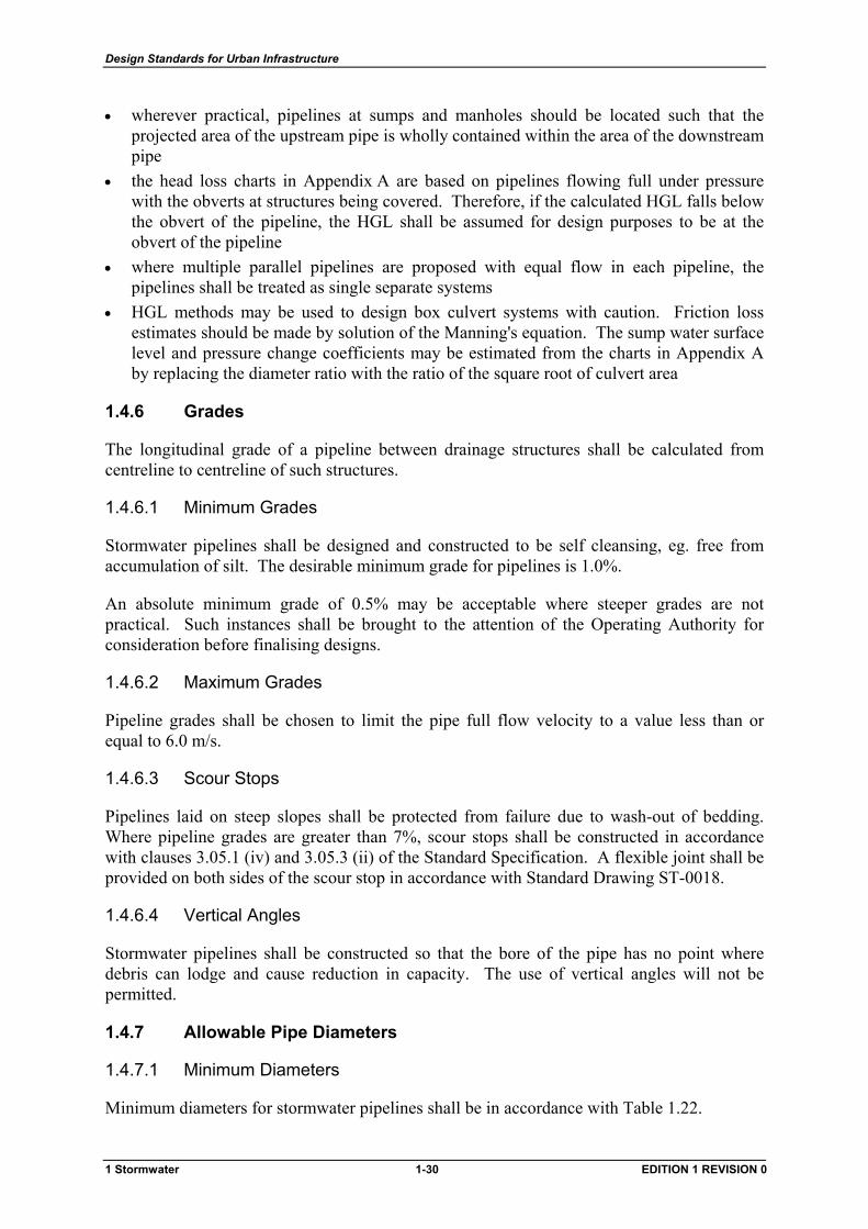
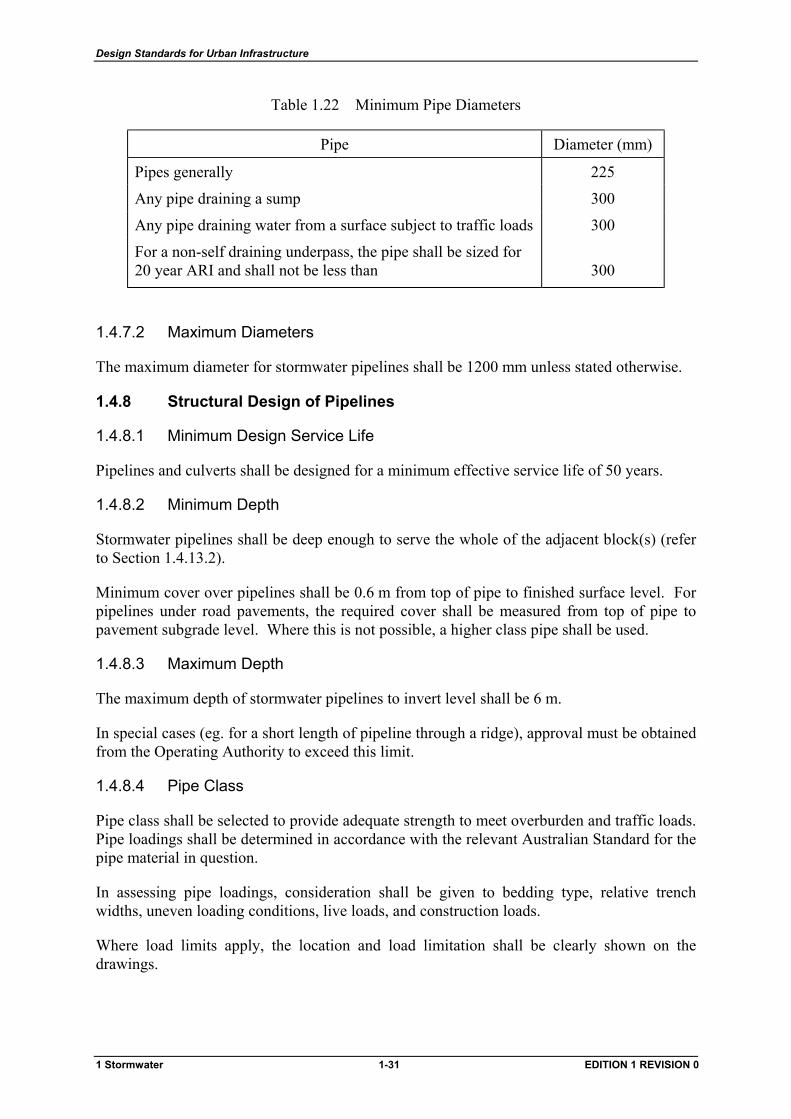
Table 1.22 Minimum Pipe Diameters
Pipe Diameter (mm)
Pipes generally 225
Any pipe draining a sump 300
Any pipe draining water from a surface subject to traffic loads 300
For a non-self draining underpass, the pipe shall be sized for 20 year ARI and shall not be less than
300
1.4.7.2 Maximum Diameters
The maximum diameter for stormwater pipelines shall be 1200 mm unless stated otherwise.
1.4.8 Structural Design of Pipelines
1.4.8.1 Minimum Design Service Life
Pipelines and culverts shall be designed for a minimum effective service life of 50 years.
1.4.8.2 Minimum Depth
Stormwater pipelines shall be deep enough to serve the whole of the adjacent block(s) (refer to Section 1.4.13.2).
Minimum cover over pipelines shall be 0.6 m from top of pipe to finished surface level. For pipelines under road pavements, the required cover shall be measured from top of pipe to pavement subgrade level. Where this is not possible, a higher class pipe shall be used.
1.4.8.3 Maximum Depth
The maximum depth of stormwater pipelines to invert level shall be 6 m.
In special cases (eg. for a short length of pipeline through a ridge), approval must be obtained from the Operating Authority to exceed this limit.
1.4.8.4 Pipe Class
Pipe class shall be selected to provide adequate strength to meet overburden and traffic loads. Pipe loadings shall be determined in accordance with the relevant Australian Standard for the pipe material in question.
In assessing pipe loadings, consideration shall be given to bedding type, relative trench widths, uneven loading conditions, live loads, and construction loads.
Where load limits apply, the location and load limitation shall be clearly shown on the drawings.
1 Stormwater 1-31 EDITION 1 REVISION 0
Design Standards for Urban Infrastructure
1.4.9 Connection to Structures
Where pipes are connected to rigid structures or are embedded in concrete, flexible joints shall be provided to minimise damage caused by differential settlement. Connections shall be constructed in accordance with Standard Drawing ST-0018.
1.4.10 Curved Pipelines
Curved stormwater pipelines may be utilised wherever there are significant advantages in their use. Ad hoc curving of pipelines to avoid obstacles such as trees, power poles, gas mains etc. is not permitted. Curved pipelines should be positioned to follow easily identifiable surface features, eg. parallel to a kerbline.
Curved pipelines shall have a constant radius.
Curved pipelines are permitted provided they are;
• in the horizontal plane only (no vertical curves) • in one direction only between successive structures (no reverse curves)
Curved pipelines shall be achieved as follows;
• curves formed by using rubber ring or flush jointed pipes, the curve shall be achieved totally within the pipe joint system so that the rubber ring or external proprietary band remains effective. Because of different pipe joint performances, the maximum deflection angle shall be as recommended by the Pipe Manufacturer
• curves formed by using splayed pipes, splayed pipes may be used to construct a curved pipeline provided that the curve is totally formed by the splays
splayed pipes shall be either;
factory formed (preferred), or
field formed by cutting standard pipes with an approved cutting device
Design drawings shall show the following curve information;
• centreline radius • pipe type (normal or splayed) • effective length of individual pipes (if other than standard length) • type of jointing
The Designer shall submit documentation to show that the above details are within the Pipe Manufacturer’s specifications.
1.4.11 Branch Connections
Pipeline junctions should occur within a sump, manhole, or special structure. Branch connections may be permitted provided that adequate structural strength can be achieved at the junction.
1 Stormwater 1-32 EDITION 1 REVISION 0
Design Standards for Urban Infrastructure
Allowable sizes of branch connections into pipelines of 450 mm to 1200 mm diameter are shown on Standard Drawing ST-0001.
A manhole shall be constructed on the branch pipeline within 20 m of the branch connection.
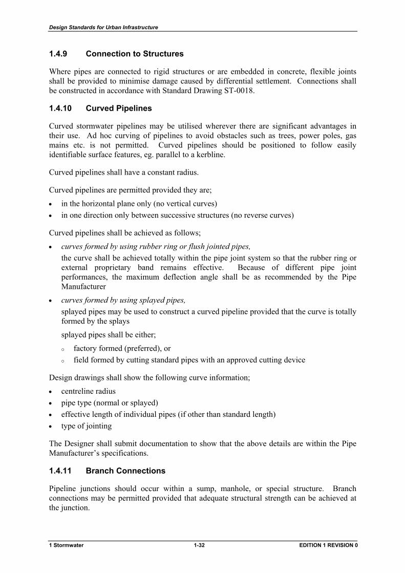
Entry angles for branches shall be between 45o and 90o to the main pipeline in horizontal direction only (refer to Figure 1.3). Vertical entry will not be permitted.
45o
min
90o
max
Figure 1.3 Permissible Entry Angles for Branch Connections
1.4.12 Dead End Pipelines
A dead end pipeline shall be constructed on a straight alignment and shall not be greater than 50 m in length.
Dead end pipelines shall drain directly to a manhole or sump. Connection of a dead end pipeline to another stormwater pipeline by a branch connection or slope junction will not be permitted.
1.4.13 Service Ties
1.4.13.1 General
Each new lease shall be individually serviced with a single service tie from a stormwater pipeline to provide for drainage of buildings on the lease. However, on redevelopment and large multi-unit sites, if the provision of a single tie will not service the entire lease or is considered impractical, the Operating Authority may permit additional service ties to be provided.
In some cases, such as blocks in a cul-de-sac or for 'preserved environmental areas', specific approval may be given for a direct connection to a stormwater pipeline to be waived and provision made for drainage to be connected to a road gutter or directed to an overland drainage path.
Service ties shall be provided in accordance with Standard Drawing ST-0001 and ST-0003.
On redevelopment sites where existing blocks have been consolidated into a larger single lease, all excess ties shall be disconnected at the main.
1 Stormwater 1-33 EDITION 1 REVISION 0
Design Standards for Urban Infrastructure
1.4.13.2 Depth
The service tie shall be deep enough such that the lease drainage system can command the whole lease at a grade not less than 0.5% with 400 mm minimum cover within the lease.
The service tie depth shall be within the following limits;
• 600 mm minimum cover over lease drainage pipe at the service tie connection • 3.0 m maximum cover over lease drainage pipe at the service tie connection
1.4.13.3 Location
Wherever practical, a service tie should be connected to a manhole or sump in preference to a separate connection into a stormwater pipeline.
Direct connection of service ties to floodway low flow pipes or inverts will not be permitted.
A service tie connected to a stormwater pipeline shall be at right angles to the pipeline with the actual inlet made using a 45o junction pipe.
Where a service tie is connected to a manhole or sump, the connection angle shall be greater than or equal to 90o to the centreline of the downstream pipeline.
Where the stormwater pipeline is located outside the lease, the service tie shall terminate at the lease boundary.
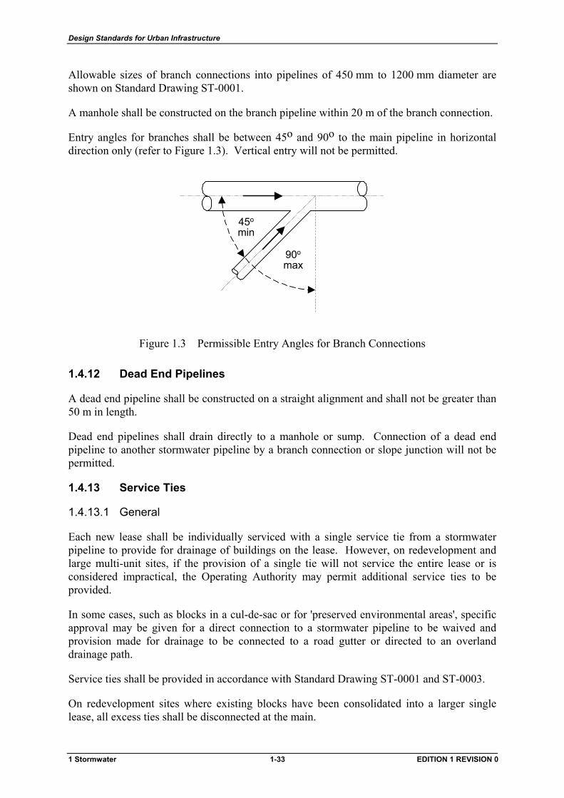
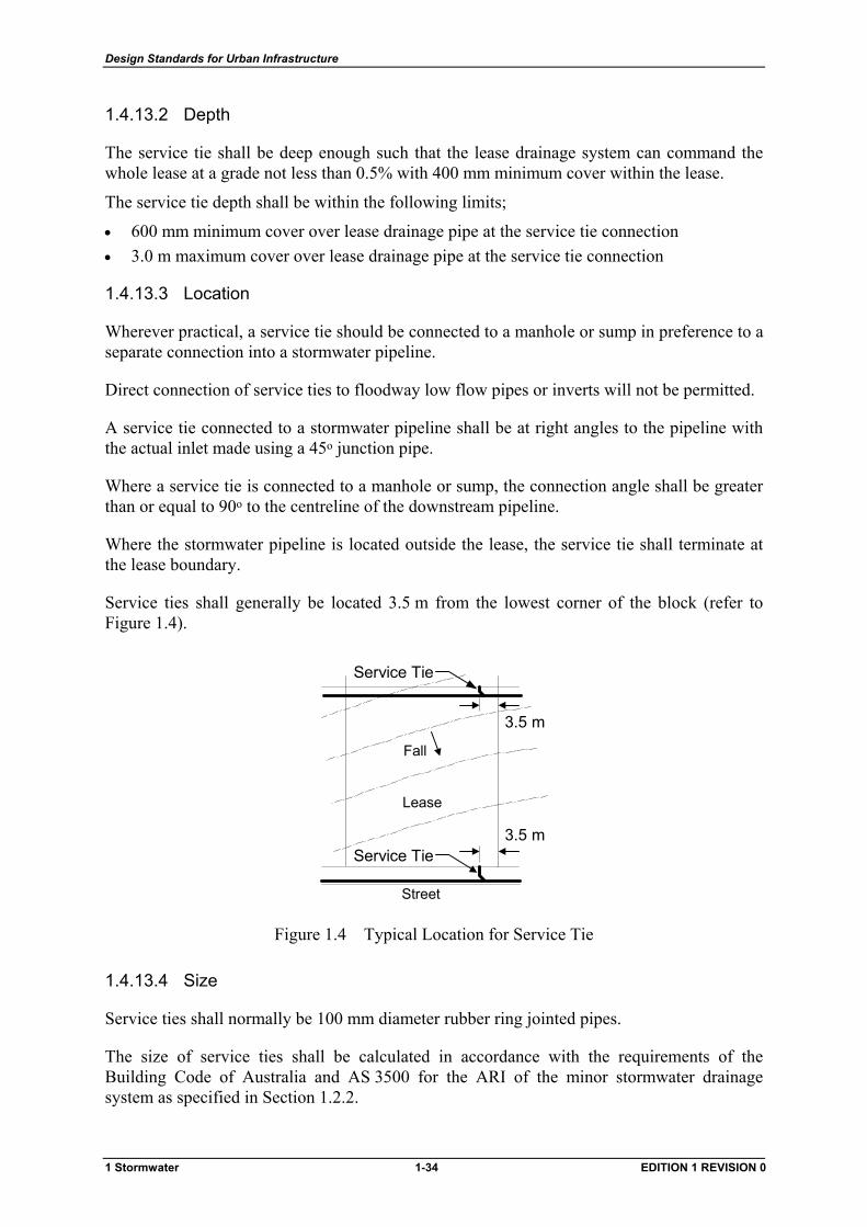
Service ties shall generally be located 3.5 m from the lowest corner of the block (refer to Figure 1.4).
Fall
Lease
3.5 m
Street
3.5 m
Service Tie
Service Tie
Figure 1.4 Typical Location for Service Tie
1.4.13.4 Size
Service ties shall normally be 100 mm diameter rubber ring jointed pipes.
The size of service ties shall be calculated in accordance with the requirements of the Building Code of Australia and AS 3500 for the ARI of the minor stormwater drainage system as specified in Section 1.2.2.
1 Stormwater 1-34 EDITION 1 REVISION 0
Design Standards for Urban Infrastructure
1.4.13.5 Grade
Service ties shall be constructed at a grade between 0.5% and 10.0% and terminate in a sealed pipe socket.
If required, service ties may be connected to the pipeline at a steeper grade by using a suitable branch connection or 45o riser. Such cases shall be brought to the attention of the Operating Authority for consideration.
1.4.13.6 Maximum Length
The maximum length of a service tie shall be 20 m.
1.4.13.7 Connections
Service tie connections into 225 mm to 375 mm diameter pipelines shall be made by means of a rubber ring jointed slope junction, or approved saddle junction, and 45o bend plus an appropriate length of pipe with the branch end sealed.
Service tie connections into 450 mm to 600 mm diameter pipelines shall be made by means of a slope connection made by the Pipe Manufacturer. The tie piece shall be as short as possible and consist of a 45o angled socket piece epoxy jointed.
Where the stormwater pipeline is 450 mm or larger, service ties may be connected as branch connections as detailed on Standard Drawing ST-0001.
1.4.13.8 Marking
Service tie locations shall be identified with a plastic tape. The tape shall be nominally 75 mm wide and coloured ‘blue’ to BS 4800 No.10C31 in accordance with the latest edition of AS 2648.
The tape shall be secured to the end of the service tie and brought vertically to the surface and attached to a marker stake. The marker stake shall protrude at least 300 mm above the finished surface.
1.4.14 Culverts
1.4.14.1 General
Box and Pipe culverts shall be sized in accordance with the Manufacturer’s recommended design charts. Entrance loss coefficients shall be in accordance with Table 1.23.
Box culverts shall be designed in accordance with the latest edition of AS 1597.
Box culverts have a tendency to accumulate silt during low flow periods, especially where multiple cells are used. A means of concentrating low flows shall be provided.
Access for maintenance shall be provided to the apron of all inlet and outlet headwalls.
1 Stormwater 1-35 EDITION 1 REVISION 0
Design Standards for Urban Infrastructure
The joints of box culverts located under roadways shall be sealed against possible loss of fines under the road surface. The method of sealing shall be in accordance with the Manufacturer's recommendations and to the satisfaction of the Operating Authority.
Refer to Standard Drawings ST-0023 & ST-0024 for typical details of box culvert endwalls and headwalls.
1.4.14.2 Minor System
Box culverts may be permitted as part of the minor stormwater system where availability of cover or minimal waterway depths make the use of pipes unsuitable.
The proposed use of box culverts in lieu of standard pipes shall be brought to the attention of the Operating Authority for consideration prior to finalising designs.
1.4.14.3 Major System
Box or pipe culverts may be used as part of the major stormwater system in engineered waterways for road crossings.
Culvert crossings shall be designed for a 100 year ARI flow with an upstream freeboard of at least 0.6 m.
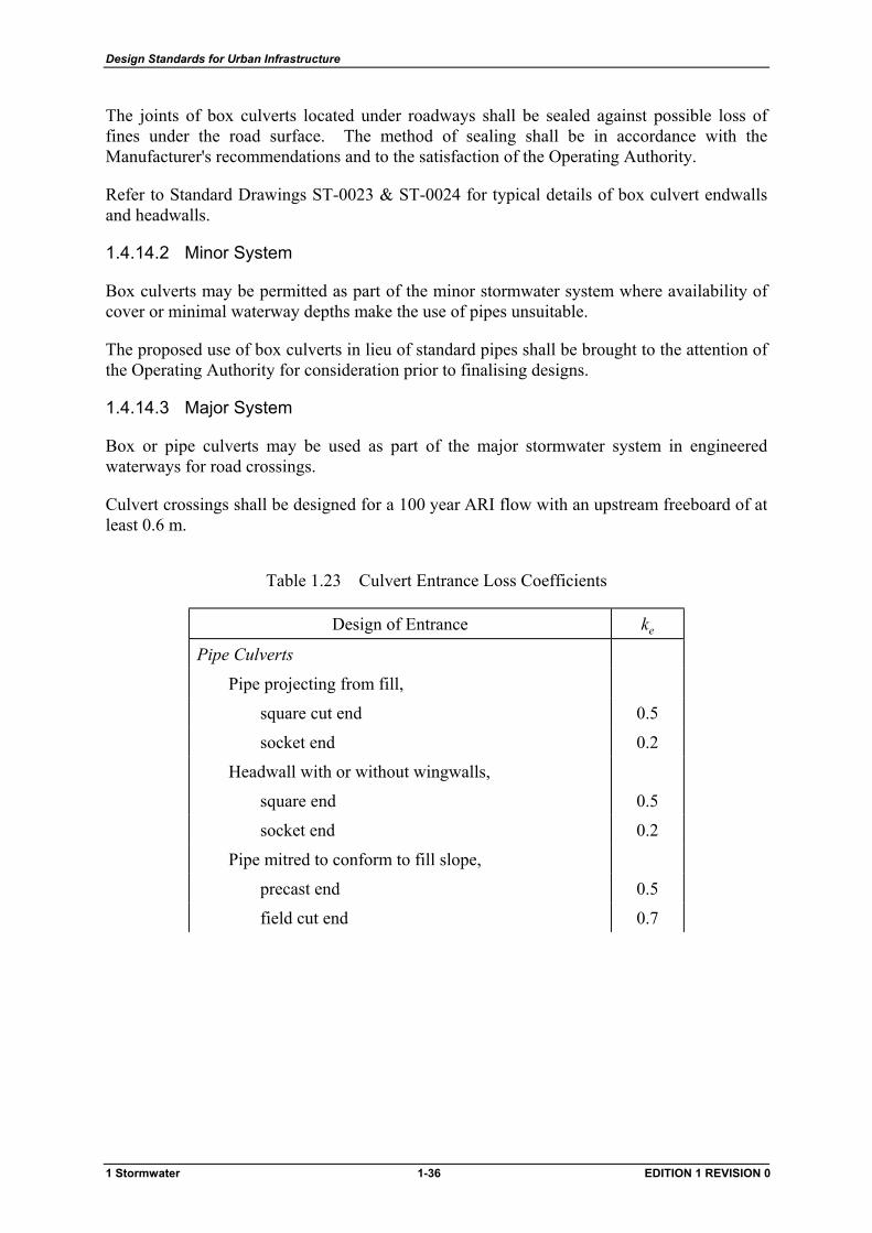
Table 1.23 Culvert Entrance Loss Coefficients
Design of Entrance ke
Pipe Culverts
Pipe projecting from fill,
square cut end 0.5
socket end 0.2
Headwall with or without wingwalls,
square end 0.5
socket end 0.2
Pipe mitred to conform to fill slope,
precast end 0.5
field cut end 0.7
1 Stormwater 1-36 EDITION 1 REVISION 0
Design Standards for Urban Infrastructure
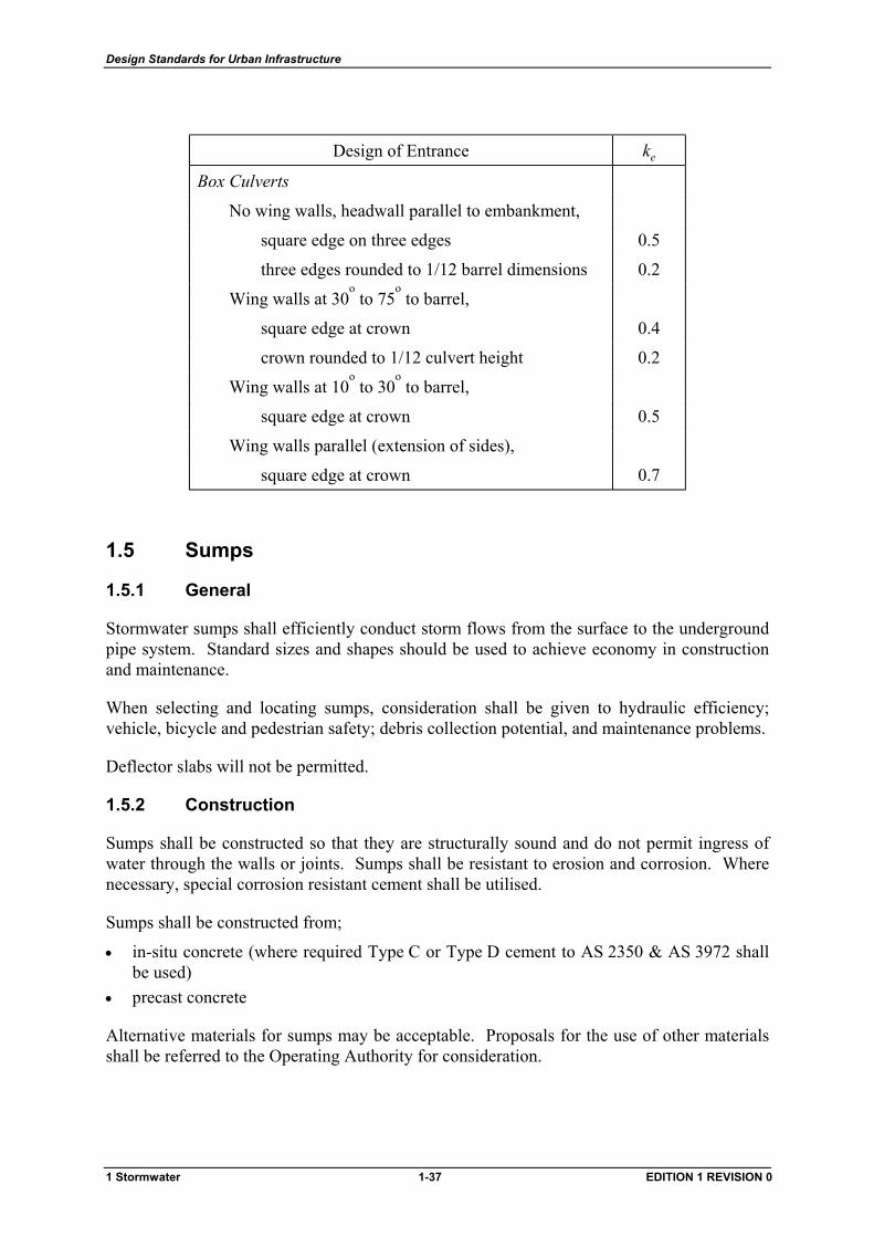
Design of Entrance ke
Box Culverts
No wing walls, headwall parallel to embankment,
square edge on three edges 0.5
three edges rounded to 1/12 barrel dimensions 0.2
Wing walls at 30o to 75
o to barrel,
square edge at crown 0.4
crown rounded to 1/12 culvert height 0.2
Wing walls at 10o to 30
o to barrel,
square edge at crown 0.5
Wing walls parallel (extension of sides),
square edge at crown 0.7
1.5 Sumps
1.5.1 General
Stormwater sumps shall efficiently conduct storm flows from the surface to the underground pipe system. Standard sizes and shapes should be used to achieve economy in construction and maintenance.
When selecting and locating sumps, consideration shall be given to hydraulic efficiency; vehicle, bicycle and pedestrian safety; debris collection potential, and maintenance problems.
Deflector slabs will not be permitted.
1.5.2 Construction
Sumps shall be constructed so that they are structurally sound and do not permit ingress of water through the walls or joints. Sumps shall be resistant to erosion and corrosion. Where necessary, special corrosion resistant cement shall be utilised.
Sumps shall be constructed from;
• in-situ concrete (where required Type C or Type D cement to AS 2350 & AS 3972 shall be used)
• precast concrete
Alternative materials for sumps may be acceptable. Proposals for the use of other materials shall be referred to the Operating Authority for consideration.
1 Stormwater 1-37 EDITION 1 REVISION 0
Design Standards for Urban Infrastructure
1.5.3 Standard Sump Types
Types of sumps for general use are;
1.5.3.1 Type R Sump
This is a double sump suitable for pipe depths up to a maximum of 3.5 m. All kerbside sumps at low points and on-grade shall generally be type R sumps.
Refer to Standard Drawing ST-0012 for details.
1.5.3.2 Type QS Sump
This is a single sump suitable for pipe depths up to a maximum of 1.8 m.
A QS sump may be used;
• at changes in direction where entry of water is not essential (ie. side entry may be sealed) • in tight radius kerb returns where the length of a type R sump is inappropriate • as a plantation sump
Refer to Standard Drawing ST-0012 for details.
1.5.3.3 Plantation Sump
This may be either a type QS or type R sump with a single or double-sided concrete apron. Plantation sumps shall be used in medians or grassed areas.
Refer to Standard Drawing ST-0013 for details.
1.5.3.4 Grated Sump
This type of sump blocks easily and should be avoided wherever possible. The use of grated sumps for roadway or underpass drainage is not permitted except in laneways with narrow verges where a type R or QS sump would conflict with other services.
Single and double-grated sumps may be used in paved pedestrian areas for pipe depths up to a maximum of 1.0 m, subject to the following conditions;
• the sump catchment area is minor • grates shall conform to the requirements of AS 3996 • the inlet capacity of grated sumps shall be assumed to be zero in the design of the major
drainage system (ie. allowance for 100% blockage) • in the event of blockage of the inlets, the resulting depth of flooding shall not exceed
50 mm and a safe passage for overflow shall be provided • light duty grates will not be permitted • all grates shall be hinged and bolted
Refer to Standard Drawing ST-0013 for details.
1 Stormwater 1-38 EDITION 1 REVISION 0
Design Standards for Urban Infrastructure
1.5.3.5 High Inlet Capacity
Where high inlet capacity is required, the preferred solution is multiple type R sumps placed side by side.
As an alternative to multiple type R sumps, special sumps may be designed and used.
The proposed sump arrangement for any location where high inlet capacity is required shall be submitted to the Operating Authority for consideration.
Refer to Standard Drawing ST-0019 for details of multiple type R sumps.
1.5.3.6 Surcharge Sump
Surcharge sumps shall be provided;
• where branch pipelines connect to low flow pipelines in floodways • where there are shallow points in the system to form an emergency overflow relief path in
times of acute hydraulic overload or blockage of the pipe system
The surcharge capacity of the sump shall be at least twice the total inflow to the sump to allow for partial blockage of the outlet during surcharge.
Refer to Standard Drawing ST-0016 for details.
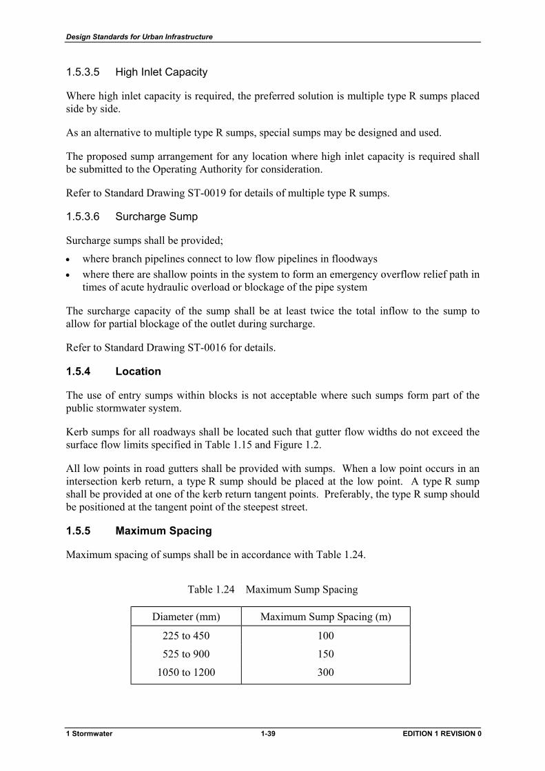
1.5.4 Location
The use of entry sumps within blocks is not acceptable where such sumps form part of the public stormwater system.
Kerb sumps for all roadways shall be located such that gutter flow widths do not exceed the surface flow limits specified in Table 1.15 and Figure 1.2.
All low points in road gutters shall be provided with sumps. When a low point occurs in an intersection kerb return, a type R sump should be placed at the low point. A type R sump shall be provided at one of the kerb return tangent points. Preferably, the type R sump should be positioned at the tangent point of the steepest street.
1.5.5 Maximum Spacing
Maximum spacing of sumps shall be in accordance with Table 1.24.
Table 1.24 Maximum Sump Spacing
Diameter (mm) Maximum Sump Spacing (m)
225 to 450 100
525 to 900 150
1050 to 1200 300
1 Stormwater 1-39 EDITION 1 REVISION 0
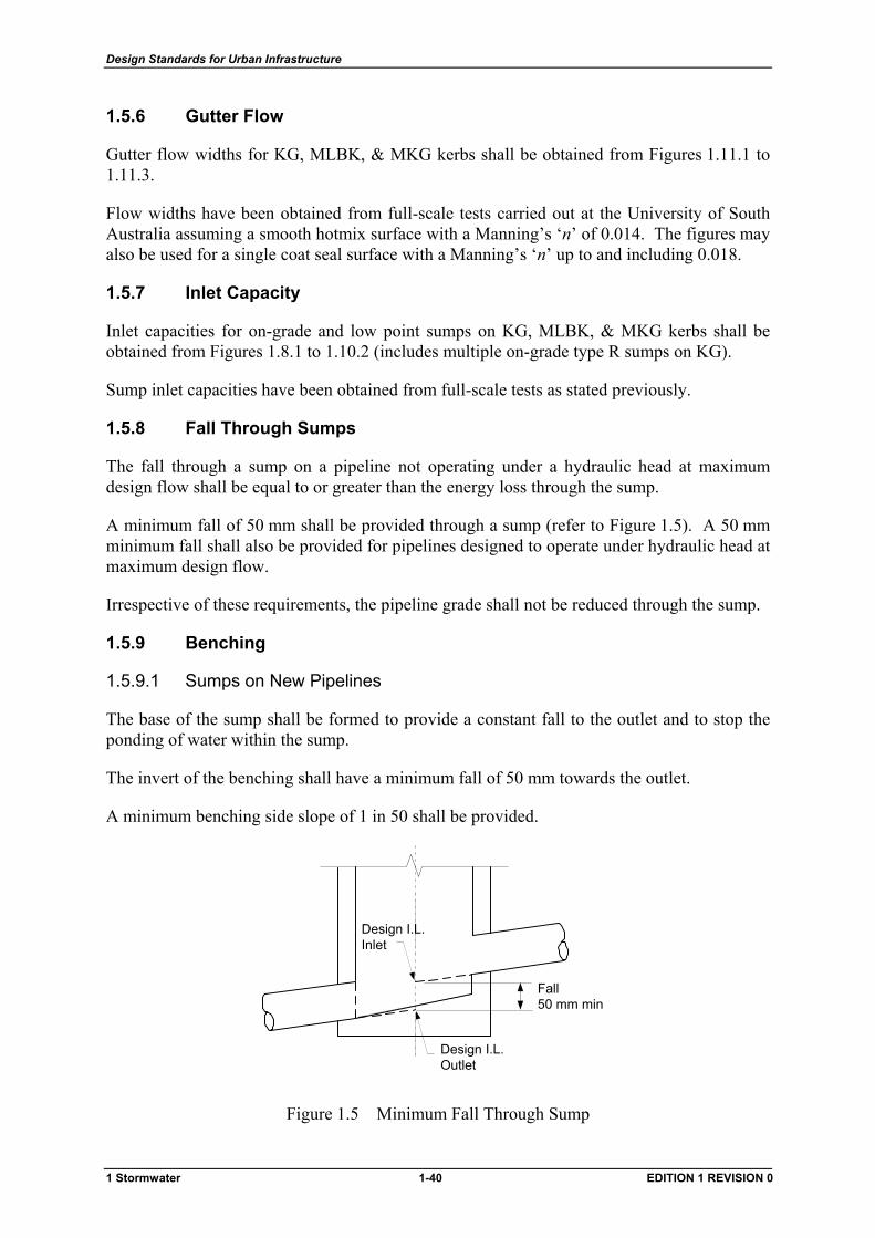
Design Standards for Urban Infrastructure
1.5.6 Gutter Flow
Gutter flow widths for KG, MLBK, & MKG kerbs shall be obtained from Figures 1.11.1 to 1.11.3.
Flow widths have been obtained from full-scale tests carried out at the University of South Australia assuming a smooth hotmix surface with a Manning’s ‘n’ of 0.014. The figures may also be used for a single coat seal surface with a Manning’s ‘n’ up to and including 0.018.
1.5.7 Inlet Capacity
Inlet capacities for on-grade and low point sumps on KG, MLBK, & MKG kerbs shall be obtained from Figures 1.8.1 to 1.10.2 (includes multiple on-grade type R sumps on KG).
Sump inlet capacities have been obtained from full-scale tests as stated previously.
1.5.8 Fall Through Sumps
The fall through a sump on a pipeline not operating under a hydraulic head at maximum design flow shall be equal to or greater than the energy loss through the sump.
A minimum fall of 50 mm shall be provided through a sump (refer to Figure 1.5). A 50 mm minimum fall shall also be provided for pipelines designed to operate under hydraulic head at maximum design flow.
Irrespective of these requirements, the pipeline grade shall not be reduced through the sump.
1.5.9 Benching
1.5.9.1 Sumps on New Pipelines
The base of the sump shall be formed to provide a constant fall to the outlet and to stop the ponding of water within the sump.
The invert of the benching shall have a minimum fall of 50 mm towards the outlet.
A minimum benching side slope of 1 in 50 shall be provided.
Design I.L.Inlet
Fall50 mm min
Design I.L.Outlet
Figure 1.5 Minimum Fall Through Sump
1 Stormwater 1-40 EDITION 1 REVISION 0
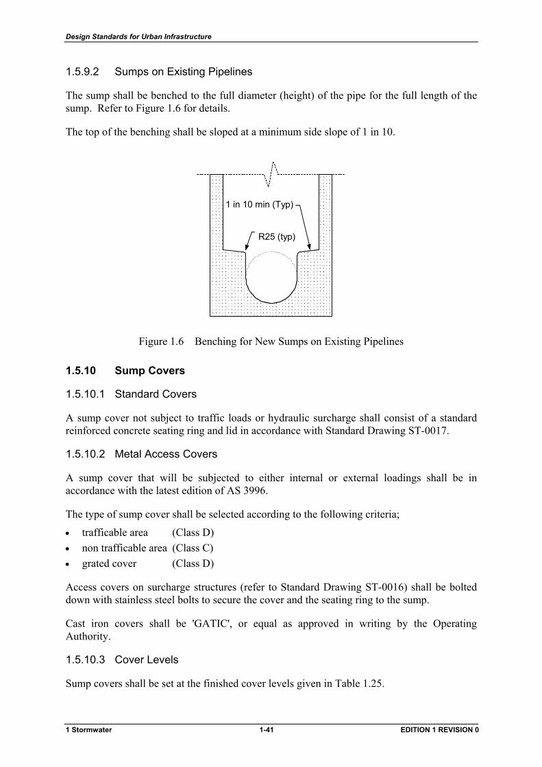
Design Standards for Urban Infrastructure
1.5.9.2 Sumps on Existing Pipelines
The sump shall be benched to the full diameter (height) of the pipe for the full length of the sump. Refer to Figure 1.6 for details.
The top of the benching shall be sloped at a minimum side slope of 1 in 10.
1 in 10 min (Typ)
R25 (typ)
���������������������������������������������������������������������������������������������������������������������������������������������������������������������������������������������������������������������������������������������������������������������������������������������������������������������������������������������������������������������������������������������������������������������������������������������������������������������������������������������������������������������������������������������������������������������������������������������������������������������������������������������������������������������������������������������������������������������������������������������������������������������������������������������������������������������������������������������������������������������������������������������������������������������������������������������������������������������������������������������������������������������������������������������������������������������������������������������������������
Figure 1.6 Benching for New Sumps on Existing Pipelines
1.5.10 Sump Covers
1.5.10.1 Standard Covers
A sump cover not subject to traffic loads or hydraulic surcharge shall consist of a standard reinforced concrete seating ring and lid in accordance with Standard Drawing ST-0017.
1.5.10.2 Metal Access Covers
A sump cover that will be subjected to either internal or external loadings shall be in accordance with the latest edition of AS 3996.
The type of sump cover shall be selected according to the following criteria;
• trafficable area (Class D) • non trafficable area (Class C) • grated cover (Class D)
Access covers on surcharge structures (refer to Standard Drawing ST-0016) shall be bolted down with stainless steel bolts to secure the cover and the seating ring to the sump.
Cast iron covers shall be 'GATIC', or equal as approved in writing by the Operating Authority.
1.5.10.3 Cover Levels
Sump covers shall be set at the finished cover levels given in Table 1.25.
1 Stormwater 1-41 EDITION 1 REVISION 0
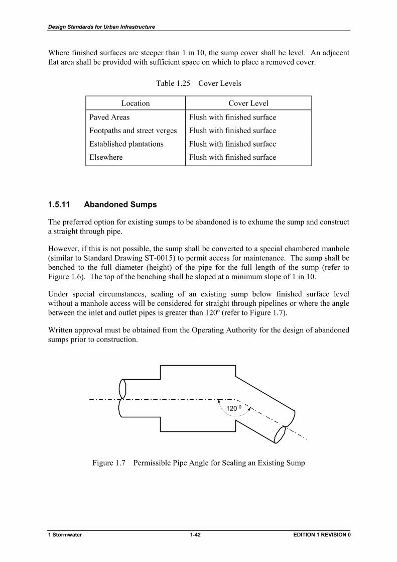
Design Standards for Urban Infrastructure
Where finished surfaces are steeper than 1 in 10, the sump cover shall be level. An adjacent flat area shall be provided with sufficient space on which to place a removed cover.
Table 1.25 Cover Levels
Location Cover Level
Paved Areas Flush with finished surface
Footpaths and street verges Flush with finished surface
Established plantations Flush with finished surface
Elsewhere Flush with finished surface
1.5.11 Abandoned Sumps
The preferred option for existing sumps to be abandoned is to exhume the sump and construct a straight through pipe.
However, if this is not possible, the sump shall be converted to a special chambered manhole (similar to Standard Drawing ST-0015) to permit access for maintenance. The sump shall be benched to the full diameter (height) of the pipe for the full length of the sump (refer to Figure 1.6). The top of the benching shall be sloped at a minimum slope of 1 in 10.
Under special circumstances, sealing of an existing sump below finished surface level without a manhole access will be considered for straight through pipelines or where the angle between the inlet and outlet pipes is greater than 120º (refer to Figure 1.7).
Written approval must be obtained from the Operating Authority for the design of abandoned sumps prior to construction.
120 0
Figure 1.7 Permissible Pipe Angle for Sealing an Existing Sump
1 Stormwater 1-42 EDITION 1 REVISION 0
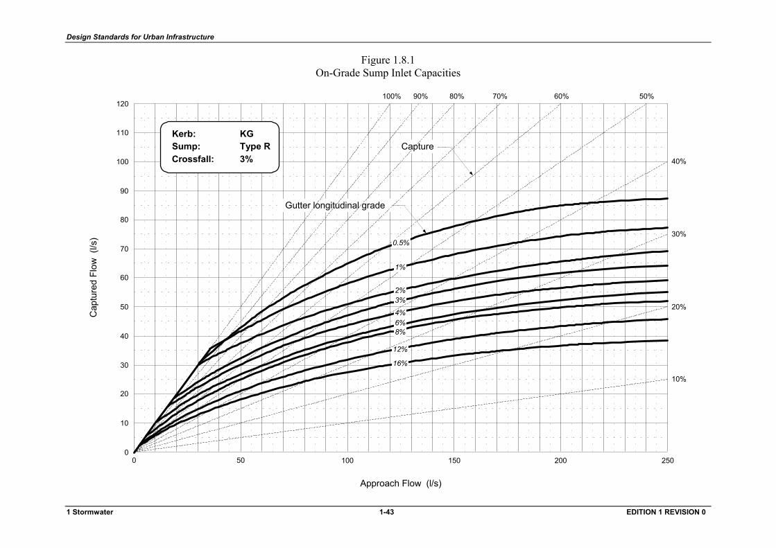
Design Standards for Urban Infrastructure
Figure 1.8.1 On-Grade Sump Inlet Capacities
50 1000 150 200 250
10
20
30
40
50
60
70
80
90
100
0
110
120100% 90% 80% 70% 60% 50%
40%
30%
20%
10%
Capture
Gutter longitudinal grade
Kerb:Sump:Crossfall:
KGType R3%
1%
0.5%
12%
2%3%
6%8%
16%
4%
Approach Flow (l/s)
Cap
ture
d Fl
ow (
l/s)
1 Stormwater 1-43 EDITION 1 REVISION 0
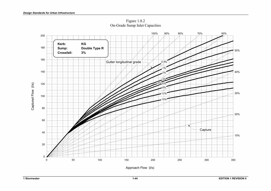
Design Standards for Urban Infrastructure
Figure 1.8.2 On-Grade Sump Inlet Capacities
100% 90% 80% 70% 60%
50%
40%
Approach Flow (l/s)
Cap
ture
d Fl
ow (
l/s)
30%
20%
10%
50 1000 150 200 250 300 3500
20
40
60
80
100
120
140
160
180
200
1%
0.5%
12%
2%
8%
15%
6%3%
4%
Gutter longitudinal grade
Capture
Kerb:Sump:Crossfall:
KGDouble Type R3%
1 Stormwater 1-44 EDITION 1 REVISION 0
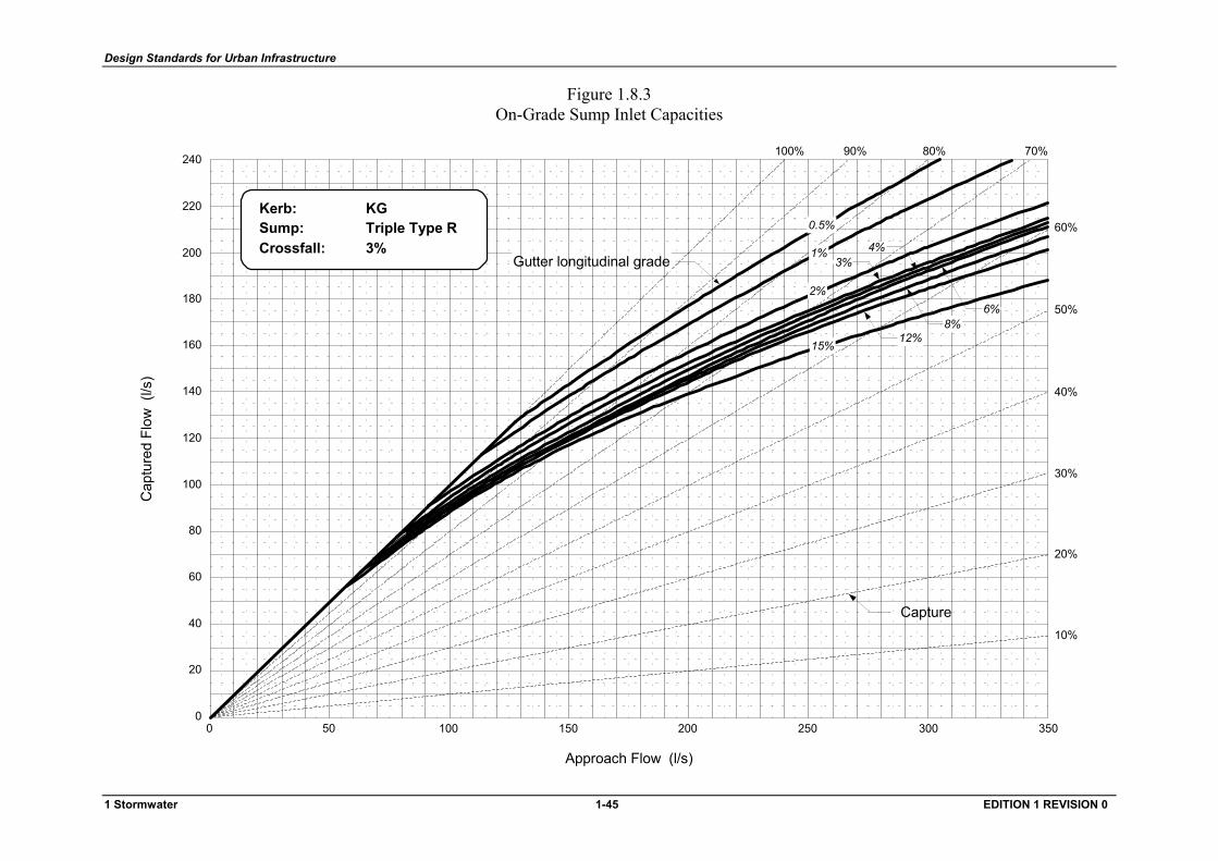
Design Standards for Urban Infrastructure
Figure 1.8.3 On-Grade Sump Inlet Capacities
100% 90% 80% 70%
60%
50%
40%
Approach Flow (l/s)
Cap
ture
d Fl
ow (
l/s)
30%
20%
10%
50 1000 150 200 250 300 3500
20
40
60
80
100
120
140
160
180
200 Gutter longitudinal grade
Capture
Kerb:Sump:Crossfall:
KGTriple Type R3%
220
240
0.5%
1%
12%
2%
8%
15%
6%
3%4%
1 Stormwater 1-45 EDITION 1 REVISION 0
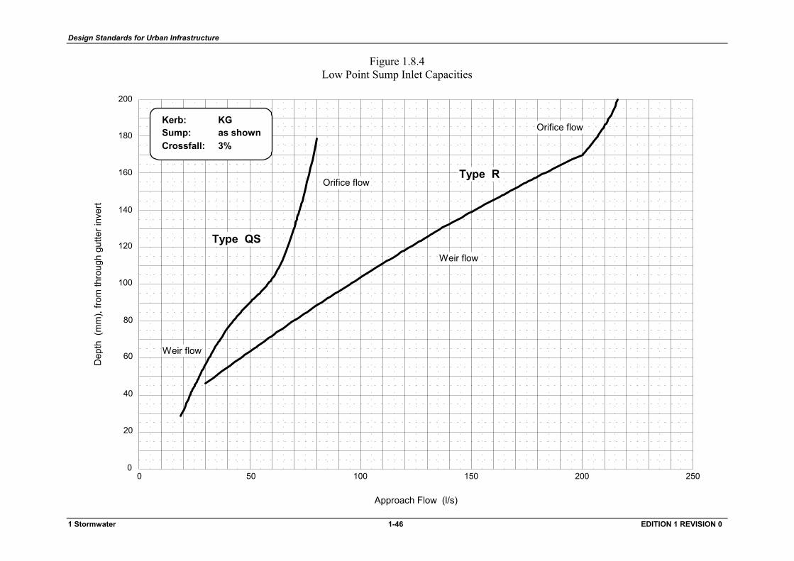
Design Standards for Urban Infrastructure
Figure 1.8.4 Low Point Sump Inlet Capacities
Weir flow
Orifice flow
Weir flow
Orifice flowType R
Type QS
50 1000 150 200 250
20
40
60
80
100
0
120
140
160
180
200
Kerb:Sump:Crossfall:
Approach Flow (l/s)
Dep
th (
mm
), fro
m th
roug
h gu
tter i
nver
t
KGas shown3%
1 Stormwater 1-46 EDITION 1 REVISION 0

Design Standards for Urban Infrastructure
Figure 1.9.1 On-Grade Sump Inlet Capacities
50 1000 150 200 250
10
20
30
40
50
60
70
80
90
100
0
110
120
100% 90% 80% 70% 60%
50%
40%
Approach Flow (l/s)
Cap
ture
d Fl
ow (
l/s)
Gutter longitudinal grade
Capture
1%
0.5%
12%
2%
6%
8%
16%
4%
30%
20%
10%
130
150
140Kerb:Sump:Crossfall:
MLBKType R3%
1 Stormwater 1-47 EDITION 1 REVISION 0
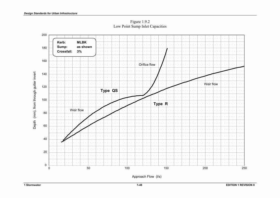
Design Standards for Urban Infrastructure
Figure 1.9.2 Low Point Sump Inlet Capacities
50 1000 150 200 250
20
40
60
80
100
0
120
140
160
180
200
Approach Flow (l/s)
Dep
th (
mm
), fro
m th
roug
h gu
tter i
nver
t
Kerb:Sump:Crossfall:
Type R
Orifice flow
Weir flow
Type QS
Weir flow
MLBKas shown3%
1 Stormwater 1-48 EDITION 1 REVISION 0
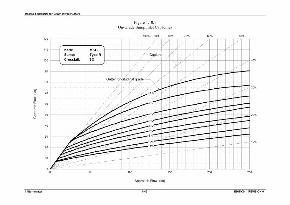
Design Standards for Urban Infrastructure
Figure 1.10.1 On-Grade Sump Inlet Capacities
50 1000 150 200 250
10
20
30
40
50
60
70
80
90
100
0
110
120100% 90% 80% 70% 60% 50%
40%
Approach Flow (l/s)
Cap
ture
d Fl
ow (
l/s)
Kerb:Sump:Crossfall:
MKGType R3%
1%
0.5%
12%
2%
3%
6%8%
16%
4%
30%
20%
10%
Gutter longitudinal grade
Capture
1 Stormwater 1-49 EDITION 1 REVISION 0
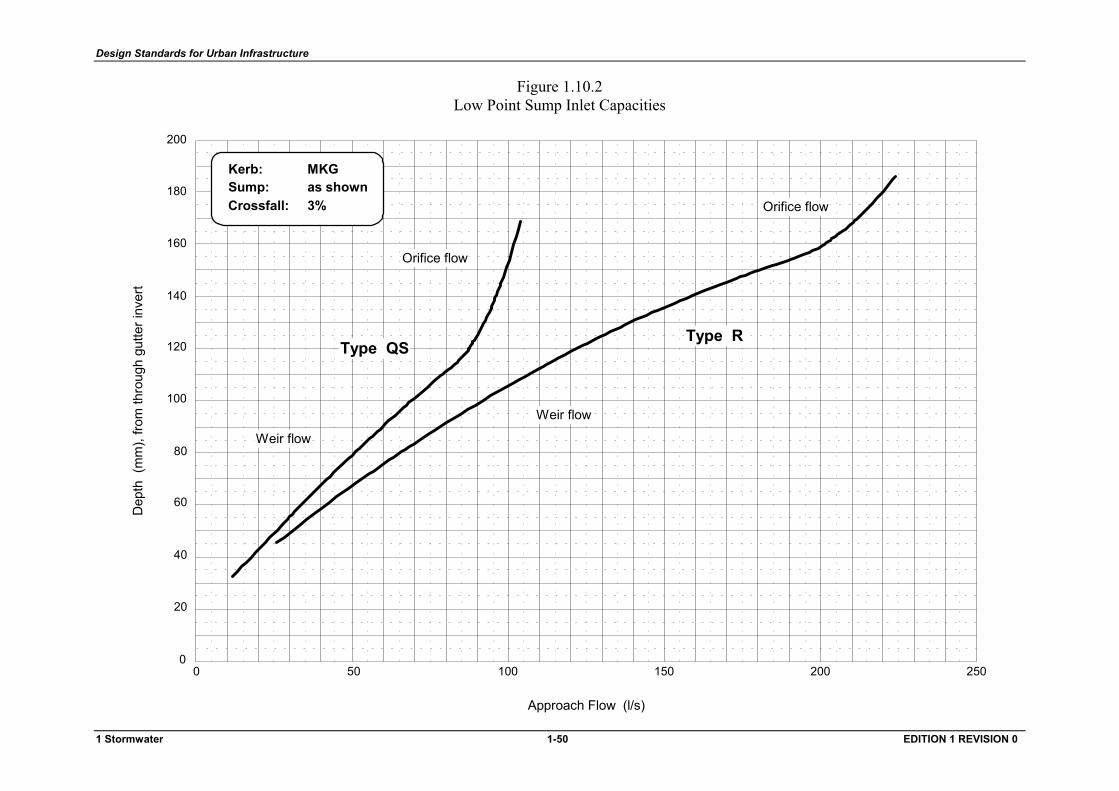
Design Standards for Urban Infrastructure
Figure 1.10.2 Low Point Sump Inlet Capacities
50 1000 150 200 250
20
40
60
80
100
0
120
140
160
180
200
Approach Flow (l/s)
Dep
th (
mm
), fro
m th
roug
h gu
tter i
nver
t
Kerb:Sump:Crossfall: Orifice flow
Orifice flow
Weir flow
Type QS
Weir flow
MKGas shown3%
Type R
1 Stormwater 1-50 EDITION 1 REVISION 0
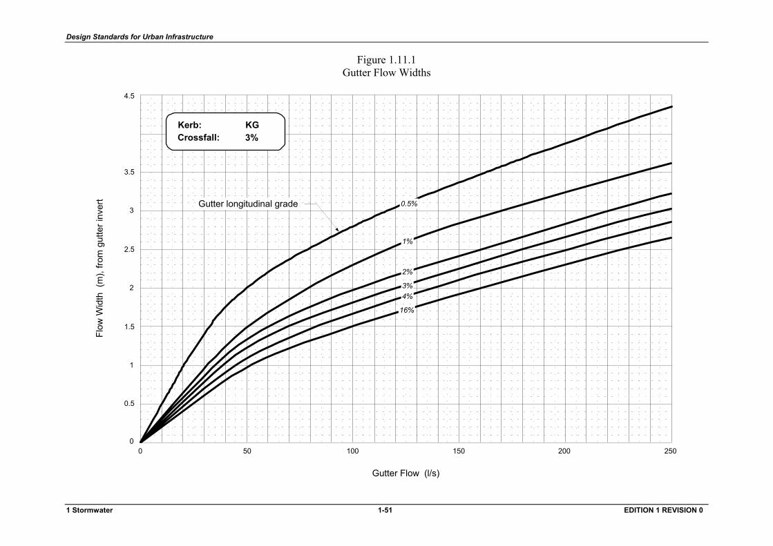
Design Standards for Urban Infrastructure
Figure 1.11.1 Gutter Flow Widths
Gutter Flow (l/s)
Flow
Wid
th (
m),
from
gut
ter i
nver
t
0.5
1
1.5
2
2.5
0
3
3.5
4.5
50 1000 150 200 250
Gutter longitudinal grade
1%
0.5%
2%
3%
16%
4%
Kerb:Crossfall:
KG3%
1 Stormwater 1-51 EDITION 1 REVISION 0
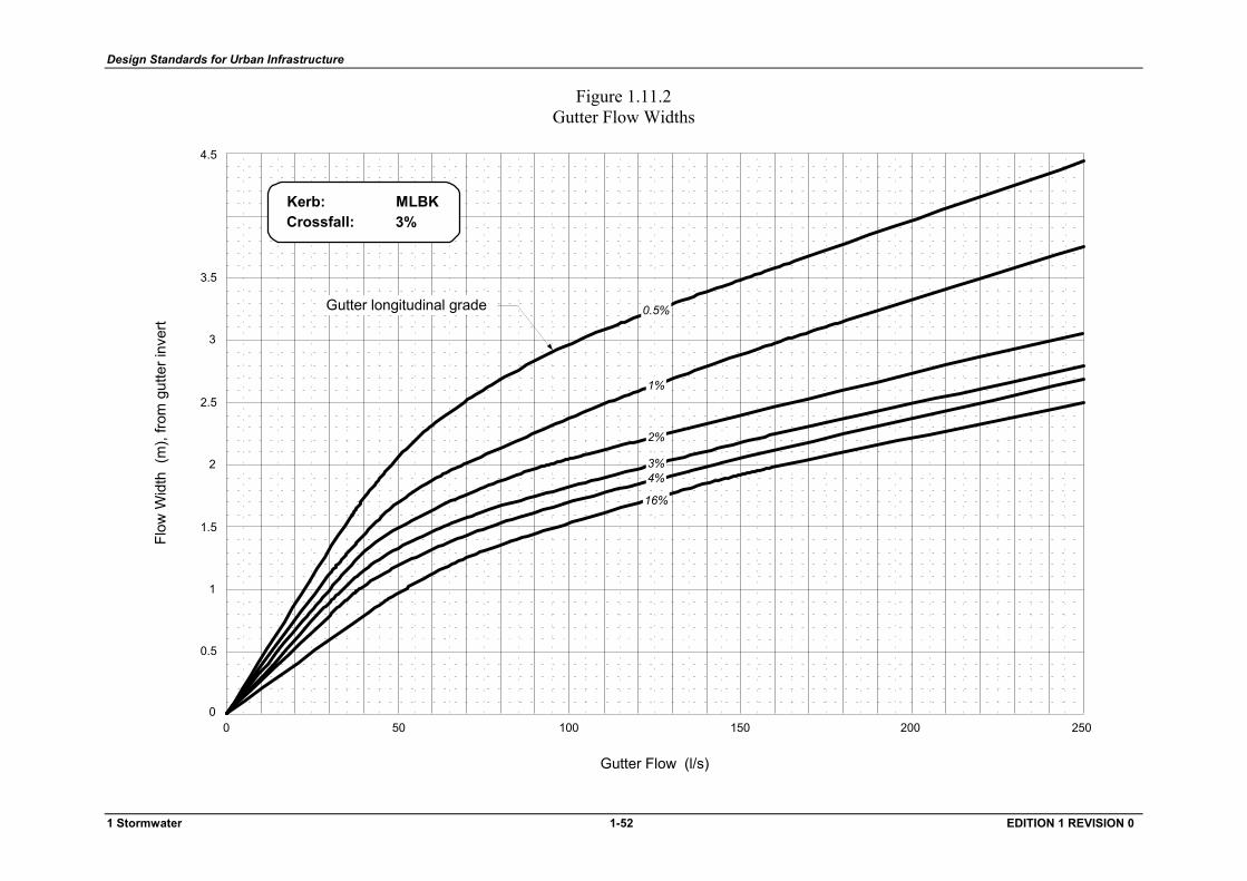
Design Standards for Urban Infrastructure
Figure 1.11.2 Gutter Flow Widths
Gutter Flow (l/s)
Flow
Wid
th (
m),
from
gut
ter i
nver
t
0.5
1
1.5
2
2.5
0
3
3.5
4.5
50 1000 150 200 250
Gutter longitudinal grade
Kerb:Crossfall:
MLBK3%
1%
0.5%
2%
3%
16%
4%
1 Stormwater 1-52 EDITION 1 REVISION 0
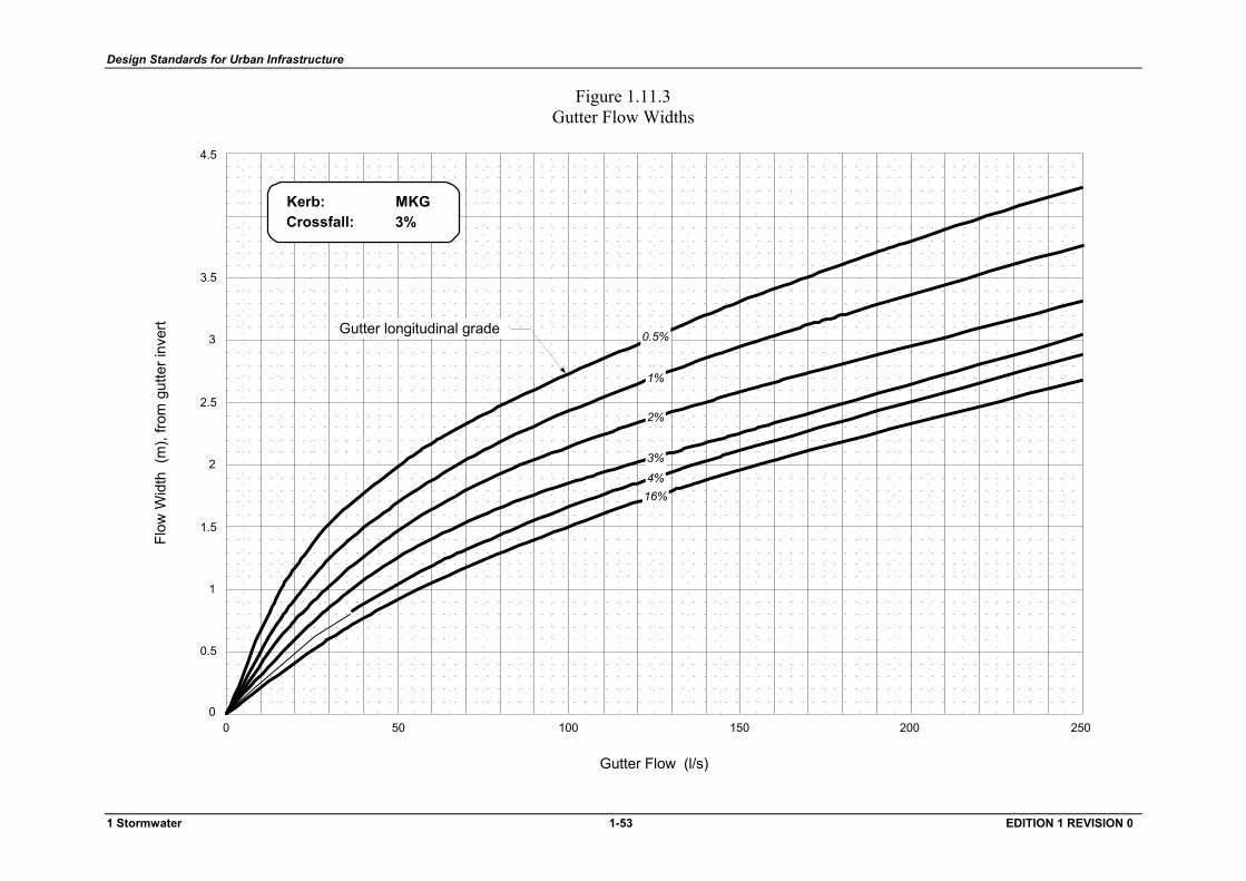
Design Standards for Urban Infrastructure
Figure 1.11.3 Gutter Flow Widths
Gutter Flow (l/s)
Flow
Wid
th (
m),
from
gut
ter i
nver
t
0.5
1
1.5
2
2.5
0
3
3.5
4.5
50 1000 150 200 250
Gutter longitudinal grade
Kerb:Crossfall:
MKG3%
1%
0.5%
2%
3%
16%4%
1 Stormwater 1-53 EDITION 1 REVISION 0

Design Standards for Urban Infrastructure
1.6 Manholes
1.6.1 General
Manholes are required to gain access to the stormwater system for maintenance purposes.
Manholes shall be located;
• where there is a high risk of blockage (eg. at changes in direction, grade, pipe size) • where junction structures are required to combine flows efficiently • at regular intervals for operation and maintenance access
Manholes shall be constructed in accordance with Standard Drawings ST-0014 or ST-0015 as required.
1.6.2 Construction
Manholes shall be constructed so that they are structurally sound and do not permit ingress of water through the walls or joints. Manholes shall be resistant to erosion and corrosion. Where necessary, special corrosion resistant cement shall be utilised.
Manholes shall be constructed from;
• in-situ concrete (where required Type C or Type D cement to AS 2350 & AS 3972 shall be used)
• precast concrete
Alternative materials for manholes may be acceptable. Proposals for the use of other materials shall be referred to the Operating Authority for consideration.
Manholes shall have a maximum depth to invert of 6 m.
Pipe connections into the cone section of a manhole will not be permitted.
1.6.3 Standard Manhole Types
The maximum length of the neck on standard manholes shall be 200 mm.
Standard step irons located over the outlet pipe shall be provided.
1.6.3.1 1050 ND Manhole
A 1050 ND manhole shall be used for pipelines from 225 mm to 675 mm diameter as shown on Standard Drawing ST-0014.
1.6.3.2 Special Chambered Manhole
A special chambered manhole shall be provided for pipelines 750 mm diameter and larger in accordance with Standard Drawing ST-0015.
It is preferable that straight-through flow be provided at these manholes by taking up angles between pipelines with curved alignments.
1 Stormwater 1-55 EDITION 1 REVISION 0
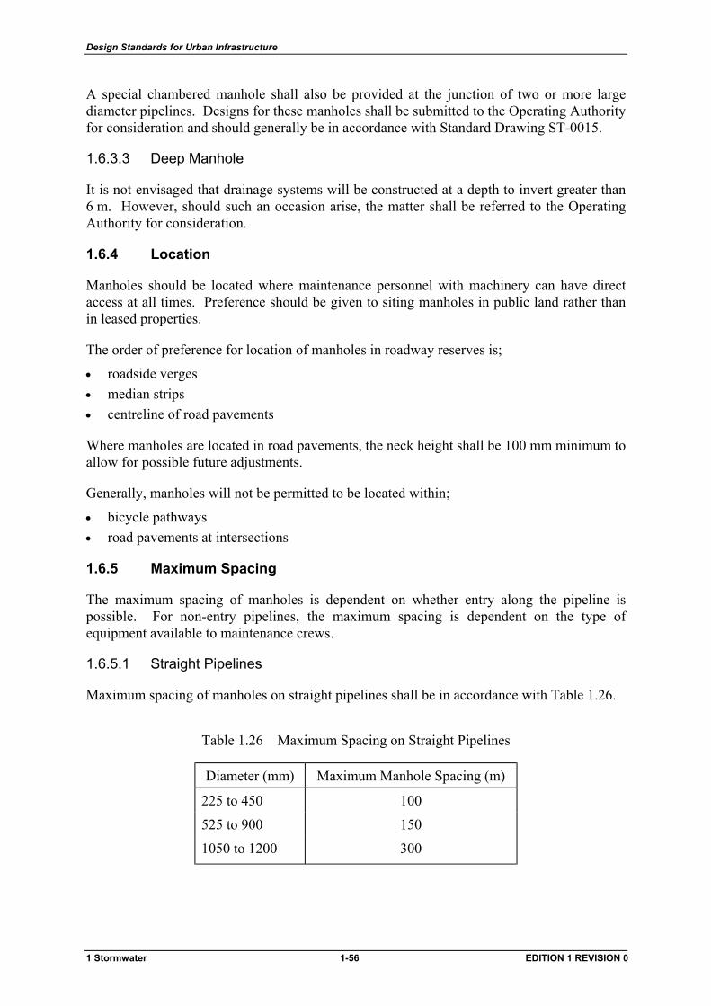
Design Standards for Urban Infrastructure
A special chambered manhole shall also be provided at the junction of two or more large diameter pipelines. Designs for these manholes shall be submitted to the Operating Authority for consideration and should generally be in accordance with Standard Drawing ST-0015.
1.6.3.3 Deep Manhole
It is not envisaged that drainage systems will be constructed at a depth to invert greater than 6 m. However, should such an occasion arise, the matter shall be referred to the Operating Authority for consideration.
1.6.4 Location
Manholes should be located where maintenance personnel with machinery can have direct access at all times. Preference should be given to siting manholes in public land rather than in leased properties.
The order of preference for location of manholes in roadway reserves is;
• roadside verges • median strips • centreline of road pavements
Where manholes are located in road pavements, the neck height shall be 100 mm minimum to allow for possible future adjustments.
Generally, manholes will not be permitted to be located within;
• bicycle pathways • road pavements at intersections
1.6.5 Maximum Spacing
The maximum spacing of manholes is dependent on whether entry along the pipeline is possible. For non-entry pipelines, the maximum spacing is dependent on the type of equipment available to maintenance crews.
1.6.5.1 Straight Pipelines
Maximum spacing of manholes on straight pipelines shall be in accordance with Table 1.26.
Table 1.26 Maximum Spacing on Straight Pipelines
Diameter (mm) Maximum Manhole Spacing (m)
225 to 450 100
525 to 900 150
1050 to 1200 300
1 Stormwater 1-56 EDITION 1 REVISION 0
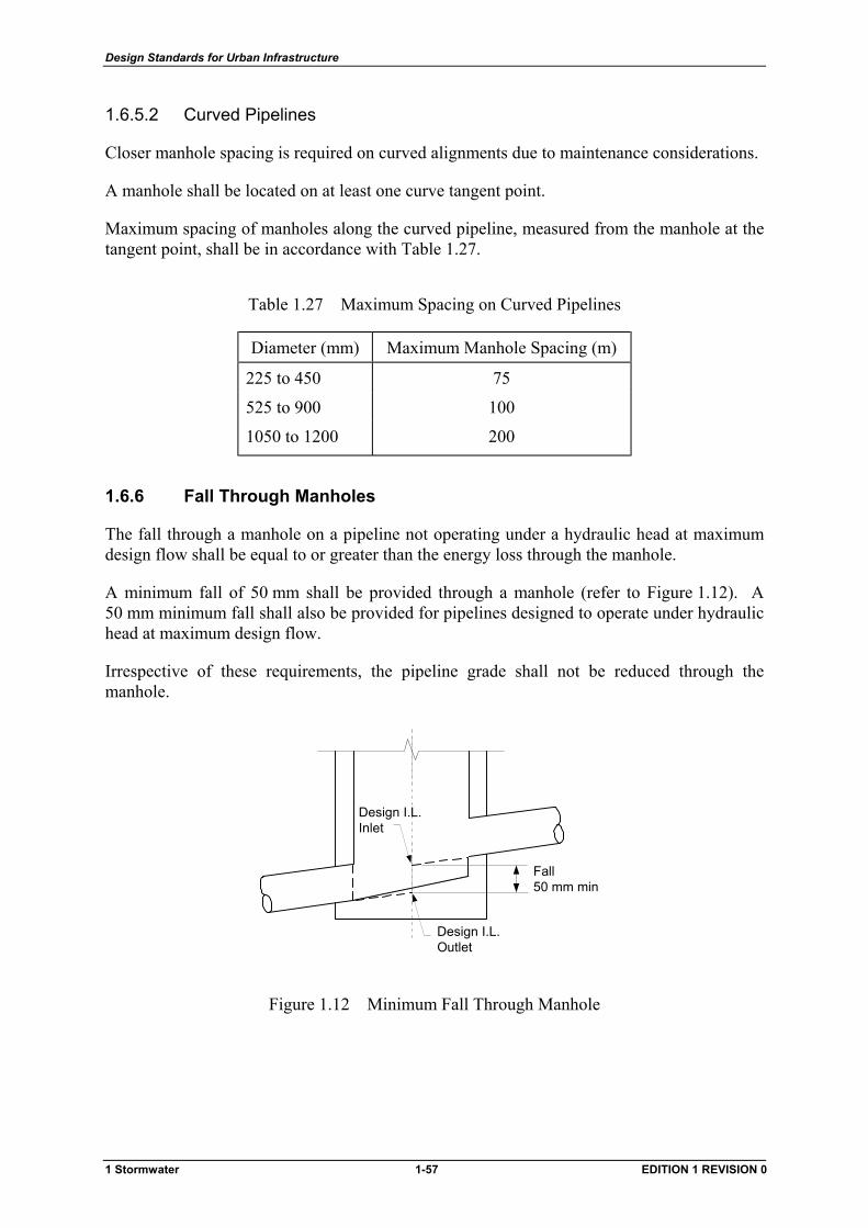
Design Standards for Urban Infrastructure
1.6.5.2 Curved Pipelines
Closer manhole spacing is required on curved alignments due to maintenance considerations.
A manhole shall be located on at least one curve tangent point.
Maximum spacing of manholes along the curved pipeline, measured from the manhole at the tangent point, shall be in accordance with Table 1.27.
Table 1.27 Maximum Spacing on Curved Pipelines
Diameter (mm) Maximum Manhole Spacing (m)
225 to 450 75
525 to 900 100
1050 to 1200 200
1.6.6 Fall Through Manholes
The fall through a manhole on a pipeline not operating under a hydraulic head at maximum design flow shall be equal to or greater than the energy loss through the manhole.
A minimum fall of 50 mm shall be provided through a manhole (refer to Figure 1.12). A 50 mm minimum fall shall also be provided for pipelines designed to operate under hydraulic head at maximum design flow.
Irrespective of these requirements, the pipeline grade shall not be reduced through the manhole.
Design I.L.Inlet
Fall50 mm min
Design I.L.Outlet
Figure 1.12 Minimum Fall Through Manhole
1 Stormwater 1-57 EDITION 1 REVISION 0
Design Standards for Urban Infrastructure
1.6.7 Benching
1.6.7.1 Depth of Benching
The minimum depth of benching for all manholes shall be half the diameter of the outlet pipe.
1.6.7.2 Radius of Benching
Changes in direction at a standard manhole shall be accommodated entirely within the structure. This shall be achieved by a curved channel of uniform radius. The minimum radius shall be three times the diameter of the largest pipe connected to the structure.
1.6.8 Manhole Centreline Offset
To accommodate benching requirements within standard manholes at a change of direction or at pipeline junctions, offsets from the pipeline centreline will be permitted.
1.6.9 Vertical Drops
Designs where the invert of an inlet pipe is located above the obvert of an outlet pipe should be avoided wherever possible. However, in cases where this is unavoidable, a free fall within the manhole should be provided.
Where a significant continuous baseflow is likely, consideration should be given to providing an external drop pipe. Such instances shall be brought to the attention of the Operating Authority for consideration.
1.6.10 Manhole Covers
1.6.10.1 Standard Covers
A manhole cover not subject to traffic loads or hydraulic surcharge shall consist of a standard reinforced concrete seating ring and lid in accordance with Standard Drawing ST-0017.
1.6.10.2 Metal Access Covers
A manhole cover that will be subjected to either internal or external loadings shall be in accordance with the latest edition of AS 3996. This type of cover shall be specified as a sealed (watertight) solid top. The class of cover shall be selected according to the following criteria;
• trafficable area (Class D) • non trafficable area (Class C) • grated cover (Class D)
Cast iron covers shall be 'GATIC', or equal as approved in writing by the Operating Authority.
1 Stormwater 1-58 EDITION 1 REVISION 0
Design Standards for Urban Infrastructure
1.6.10.3 Cover Levels
Manhole covers shall be set at the finished cover levels given in Table 1.28.
In locations where a cover at or above the surface could cause a hazard (eg. in a golf course or playing field), a cover level below the surface will be permitted providing that;
• there are no junctions or drops in the manhole • the change in direction is less than 30o • an unburied manhole is provided within 100 m • the precise location of the manhole is recorded on "work-as-executed" drawings • a heavy duty sealed cover is set at 200 mm below finished grass level
Where finished surfaces are steeper than 1 in 10, the manhole cover shall be level. An adjacent flat area shall be provided with sufficient space on which to place a removed cover.
Table 1.28 Cover Levels
Location Cover Level
Paved Areas Flush with finished surface
Footpaths and street verges Flush with finished surface
Established plantations Flush with finished surface
Elsewhere 100 mm above surface to allow for topsoiling and grassing (see note)
Note: Manhole tops shall be protected by placing fill against the top. The fill shall be graded down to natural surface at a maximum slope of 1 in 10.
1.7 Engineered Waterways
1.7.1 General Requirements
Engineered waterways are overland flow conveyance systems that are the major components of the major drainage system. Floodways and natural waterways are classified as major waterways which shall be provided wherever the estimated minor system ARI flow exceeds the capacity of two 1200 mm pipelines in parallel. Swales and roadways are classified as minor waterways which may be utilised for training overland flows to a major waterway system.
Adjoining low-lying land may be reclaimed to ensure effective surface drainage and containment of the design ARI flow within the engineered waterway.
The requirements for engineering waterways shall be approved at the Master Plan design stage.
1 Stormwater 1-59 EDITION 1 REVISION 0
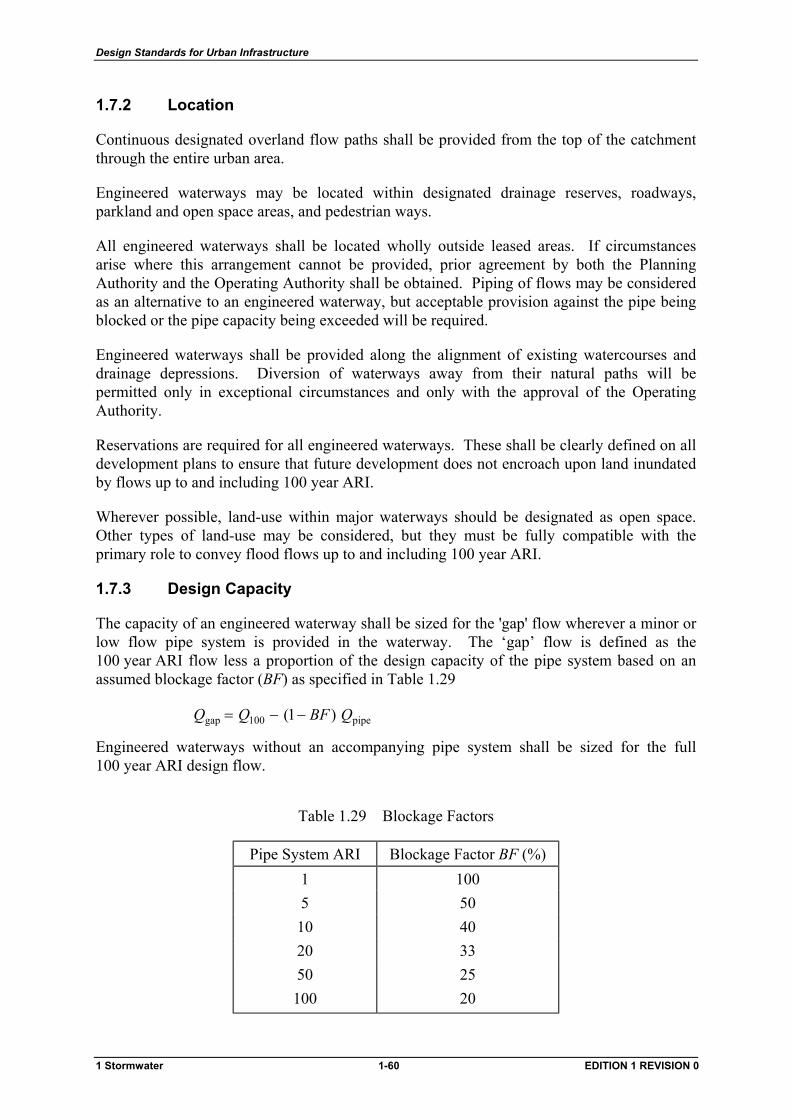
Design Standards for Urban Infrastructure
1.7.2 Location
Continuous designated overland flow paths shall be provided from the top of the catchment through the entire urban area.
Engineered waterways may be located within designated drainage reserves, roadways, parkland and open space areas, and pedestrian ways.
All engineered waterways shall be located wholly outside leased areas. If circumstances arise where this arrangement cannot be provided, prior agreement by both the Planning Authority and the Operating Authority shall be obtained. Piping of flows may be considered as an alternative to an engineered waterway, but acceptable provision against the pipe being blocked or the pipe capacity being exceeded will be required.
Engineered waterways shall be provided along the alignment of existing watercourses and drainage depressions. Diversion of waterways away from their natural paths will be permitted only in exceptional circumstances and only with the approval of the Operating Authority.
Reservations are required for all engineered waterways. These shall be clearly defined on all development plans to ensure that future development does not encroach upon land inundated by flows up to and including 100 year ARI.
Wherever possible, land-use within major waterways should be designated as open space. Other types of land-use may be considered, but they must be fully compatible with the primary role to convey flood flows up to and including 100 year ARI.
1.7.3 Design Capacity
The capacity of an engineered waterway shall be sized for the 'gap' flow wherever a minor or low flow pipe system is provided in the waterway. The ‘gap’ flow is defined as the 100 year ARI flow less a proportion of the design capacity of the pipe system based on an assumed blockage factor (BF) as specified in Table 1.29
pipe100gap )1( QBFQQ −−=
Engineered waterways without an accompanying pipe system shall be sized for the full 100 year ARI design flow.
Table 1.29 Blockage Factors
Pipe System ARI Blockage Factor BF (%) 1 100 5 50 10 40 20 33 50 25 100 20
1 Stormwater 1-60 EDITION 1 REVISION 0
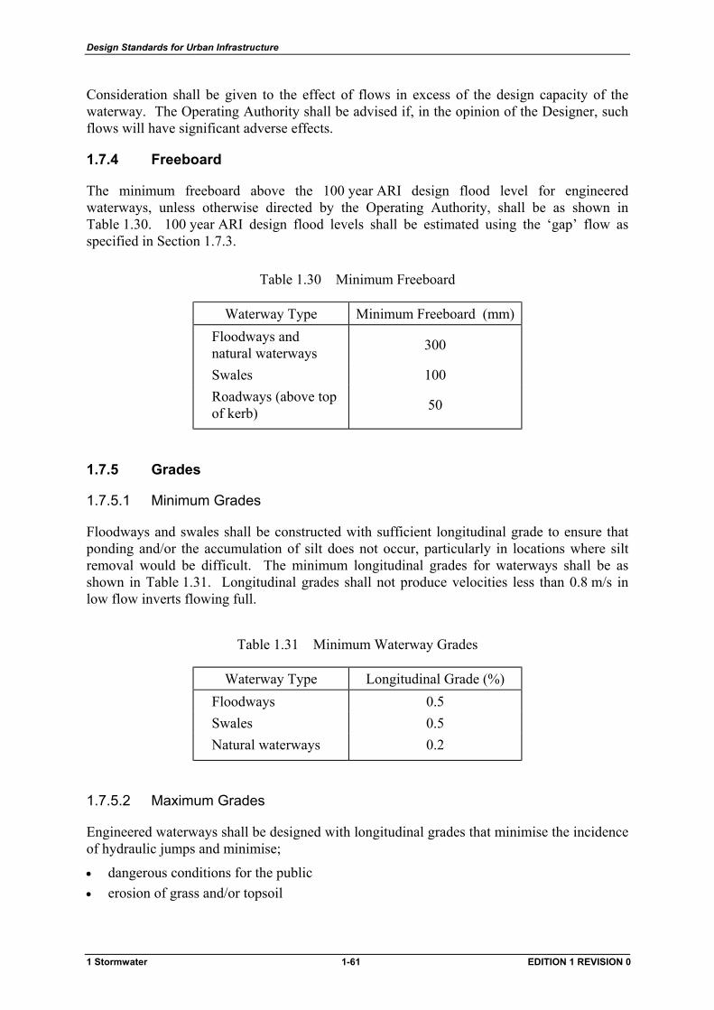
Design Standards for Urban Infrastructure
Consideration shall be given to the effect of flows in excess of the design capacity of the waterway. The Operating Authority shall be advised if, in the opinion of the Designer, such flows will have significant adverse effects.
1.7.4 Freeboard
The minimum freeboard above the 100 year ARI design flood level for engineered waterways, unless otherwise directed by the Operating Authority, shall be as shown in Table 1.30. 100 year ARI design flood levels shall be estimated using the ‘gap’ flow as specified in Section 1.7.3.
Table 1.30 Minimum Freeboard
Waterway Type Minimum Freeboard (mm) Floodways and natural waterways 300
Swales 100 Roadways (above top of kerb) 50
1.7.5 Grades
1.7.5.1 Minimum Grades
Floodways and swales shall be constructed with sufficient longitudinal grade to ensure that ponding and/or the accumulation of silt does not occur, particularly in locations where silt removal would be difficult. The minimum longitudinal grades for waterways shall be as shown in Table 1.31. Longitudinal grades shall not produce velocities less than 0.8 m/s in low flow inverts flowing full.
Table 1.31 Minimum Waterway Grades
Waterway Type Longitudinal Grade (%) Floodways 0.5 Swales 0.5 Natural waterways 0.2
1.7.5.2 Maximum Grades
Engineered waterways shall be designed with longitudinal grades that minimise the incidence of hydraulic jumps and minimise;
• dangerous conditions for the public • erosion of grass and/or topsoil
1 Stormwater 1-61 EDITION 1 REVISION 0
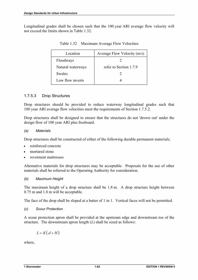
Design Standards for Urban Infrastructure
Longitudinal grades shall be chosen such that the 100 year ARI average flow velocity will not exceed the limits shown in Table 1.32.
Table 1.32 Maximum Average Flow Velocities
Location Average Flow Velocity (m/s)
Floodways 2
Natural waterways refer to Section 1.7.9
Swales 2
Low flow inverts 4
1.7.5.3 Drop Structures
Drop structures should be provided to reduce waterway longitudinal grades such that 100 year ARI average flow velocities meet the requirements of Section 1.7.5.2.
Drop structures shall be designed to ensure that the structures do not 'drown out' under the design flow of 100 year ARI plus freeboard.
(a) Materials
Drop structures shall be constructed of either of the following durable permanent materials;
• reinforced concrete • mortared stone • revetment mattresses
Alternative materials for drop structures may be acceptable. Proposals for the use of other materials shall be referred to the Operating Authority for consideration.
(b) Maximum Height
The maximum height of a drop structure shall be 1.8 m. A drop structure height between 0.75 m and 1.8 m will be acceptable.
The face of the drop shall be sloped at a batter of 1 in 1. Vertical faces will not be permitted.
(c) Scour Protection
A scour protection apron shall be provided at the upstream edge and downstream toe of the structure. The downstream apron length (L) shall be sized as follows:
( )HdKL +=
where,
1 Stormwater 1-62 EDITION 1 REVISION 0
Design Standards for Urban Infrastructure
K = 1 for hard clay = 2 for fine gravel = 2.5 for sandy loam = 3.5 to 4.5 for sand
d = 100 year ARI flow depth H = height of drop
1.7.6 Grassing
The grass species chosen for lining of an engineered waterway must be sturdy, drought resistant, easy to establish, and able to spread and develop a strong turf layer after establishment. A thick root structure is necessary to control weed growth and erosion.
Grass mixtures shall be selected in accordance with the requirements of the Standard Specification.
1.7.7 Advisory Signs
1.7.7.1 Location
Floodway advisory signs shall be provided within floodways and natural waterways. The adopted sign is one that does not inhibit people from using the environs of the waterway but rather advises them to take care at certain times.
The signs shall be located at points of congregation and generally at about 500 m intervals along waterways within the 10 year ARI floodplain. Points of congregation would be, for example, pathways leading to low-level pedestrian crossings.
1.7.7.2 Type
The sign shall be 450 mm x 600 mm with black lettering on a white light reflective plate. Refer to Standard Drawing ST-0041 for details.
Signs shall be erected back to back on a 75 mm grey galvanised steel pole and be located 1.5 m above the ground.
In general, the signs should be erected as part of waterway or landscaping contracts.
1.7.8 Floodways
1.7.8.1 General
Floodways shall conform to the following requirements;
• floodways shall be grassed with provision for low flows • footpath paving within a floodway shall be designed to withstand the design discharge in
areas of high velocity such as adjacent to underpasses
The following factors may need consideration;
• drop structures may be provided to reduce flow velocities to acceptable levels
1 Stormwater 1-63 EDITION 1 REVISION 0
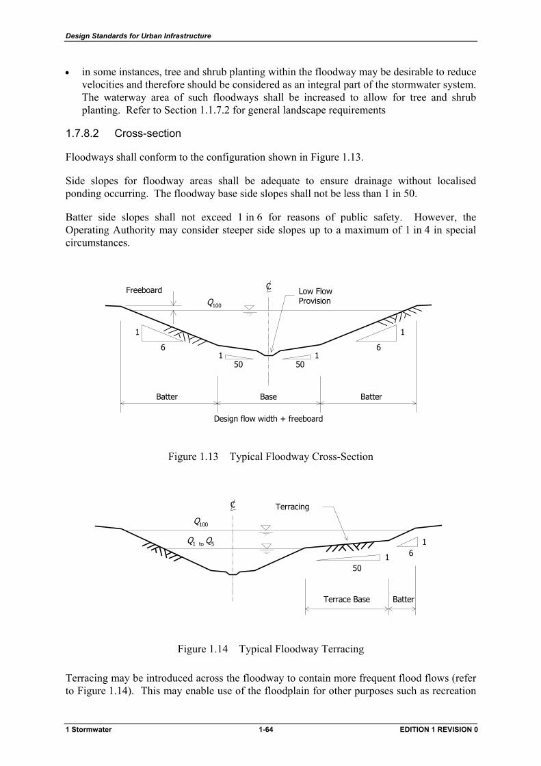
Design Standards for Urban Infrastructure
• in some instances, tree and shrub planting within the floodway may be desirable to reduce velocities and therefore should be considered as an integral part of the stormwater system. The waterway area of such floodways shall be increased to allow for tree and shrub planting. Refer to Section 1.1.7.2 for general landscape requirements
1.7.8.2 Cross-section
Floodways shall conform to the configuration shown in Figure 1.13.
Side slopes for floodway areas shall be adequate to ensure drainage without localised ponding occurring. The floodway base side slopes shall not be less than 1 in 50.
Batter side slopes shall not exceed 1 in 6 for reasons of public safety. However, the Operating Authority may consider steeper side slopes up to a maximum of 1 in 4 in special circumstances.
6
1
6
1
15050
1
Batter BatterBase
C Low FlowProvision
Freeboard
Design flow width + freeboard
Q100
Figure 1.13 Typical Floodway Cross-Section
Q100
Q1 to Q5
C Terracing
161
50
BatterTerrace Base
Figure 1.14 Typical Floodway Terracing
Terracing may be introduced across the floodway to contain more frequent flood flows (refer to Figure 1.14). This may enable use of the floodplain for other purposes such as recreation
1 Stormwater 1-64 EDITION 1 REVISION 0
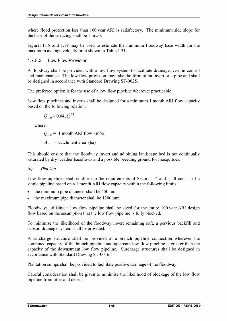
Design Standards for Urban Infrastructure
where flood protection less than 100 year ARI is satisfactory. The minimum side slope for the base of the terracing shall be 1 in 50.
Figures 1.18 and 1.19 may be used to estimate the minimum floodway base width for the maximum average velocity limit shown in Table 1.31.
1.7.8.3 Low Flow Provision
A floodway shall be provided with a low flow system to facilitate drainage, vermin control and maintenance. The low flow provision may take the form of an invert or a pipe and shall be designed in accordance with Standard Drawing ST-0025.
The preferred option is for the use of a low flow pipeline wherever practicable.
Low flow pipelines and inverts shall be designed for a minimum 1 month ARI flow capacity based on the following relation;
75.01 04.0 cm AQ =
where,
mQ 1 = 1 month ARI flow (m3/s)
cA = catchment area (ha)
This should ensure that the floodway invert and adjoining landscape bed is not continually saturated by dry weather baseflows and a possible breeding ground for mosquitoes.
(a) Pipeline
Low flow pipelines shall conform to the requirements of Section 1.4 and shall consist of a single pipeline based on a 1 month ARI flow capacity within the following limits;
• the minimum pipe diameter shall be 450 mm • the maximum pipe diameter shall be 1200 mm
Floodways utilising a low flow pipeline shall be sized for the entire 100 year ARI design flow based on the assumption that the low flow pipeline is fully blocked.
To minimise the likelihood of the floodway invert remaining soft, a pervious backfill and subsoil drainage system shall be provided.
A surcharge structure shall be provided at a branch pipeline connection wherever the combined capacity of the branch pipeline and upstream low flow pipeline is greater than the capacity of the downstream low flow pipeline. Surcharge structures shall be designed in accordance with Standard Drawing ST-0016.
Plantation sumps shall be provided to facilitate positive drainage of the floodway.
Careful consideration shall be given to minimise the likelihood of blockage of the low flow pipeline from litter and debris.
1 Stormwater 1-65 EDITION 1 REVISION 0
Design Standards for Urban Infrastructure
(b) Invert
A low flow invert may be used in the following circumstances;
• the use of pipes could result in costly excavation in solid rock • very flat waterway grades could result in problems with siltation of pipes • in specially designated areas where it is desirable to create an open water landscape
Low flow inverts should be sized in accordance with Figures 1.20 and 1.21.
Careful consideration shall be given to minimising the possibility of scour at the interface between the invert edge and the grassed surface of the floodway. It may be necessary to provide a transition zone using a stabilisation system such as reinforced grass.
Attention shall also be given to making the transition of branch pipelines as smooth as practicable to minimise turbulence and potential scour. Stabilisation may also be required on the downstream side of branch pipeline transitions.
Designated crossing points for maintenance machinery shall be provided at regular intervals of not more than 200 m.
A subsoil system shall be provided for the invert. This may take the form of a standard subsoil drain, geofabric wrapped aggregate or a strip drain. Refer to Standard Drawing ST-0025 for typical details.
Inverts shall be constructed of reinforced concrete, mortared stone, revetment mattresses or other approved materials.
1.7.8.4 At-grade Crossings
At-grade footpath and cycleway crossings of floodways will be permitted and should be designed in accordance with Standard Drawing ST-0026.
Crossings shall follow the shape and grade of the floodway as far as practical to avoid any flow restrictions and minimise changes to the flow regime.
(a) Grassed Invert
A hardstand area shall be provided at the floodway invert on the downstream side of the crossing to prevent the likelihood of water ponding on the crossing due to grass build-up.
(b) Low Flow Invert
Crossings spanning low flow inverts shall have a minimum 200 mm clearance above the base of the invert to minimise the likelihood of blockage by litter and debris.
Adequate provision for public safety shall be included in the design.
Where it is likely that maintenance vehicles will use a crossing, it shall be designed for a 7 tonne wheel load in a W-7 configuration in accordance with the AUSTROADS Bridge Code.
1 Stormwater 1-66 EDITION 1 REVISION 0
Design Standards for Urban Infrastructure
1.7.9 Natural Waterways
Natural waterways are generally in the form of steeply banked streams, which have erodible banks and bottoms, or mild channels, which are reasonably stabilised. For either type of waterway, it can be assumed initially that the changed runoff regime resulting from urbanisation will result in highly active erosional tendencies. In nearly all cases, some form of modification of the waterway will be required to create a somewhat stabilised condition for the waterway.
The design guidelines for floodways do not necessarily apply to natural waterways, but such criteria can be utilised in gauging the adequacy of a natural waterway for future changes in runoff regime.
Design criteria and techniques, which should be used in the design of natural waterways, include the following:
• channel and over-bank capacity shall be adequate for 100 year ARI • channel velocity shall not exceed the lesser of 2 m/s or the critical velocity for any
particular section. Manning’s roughness factors, n, which are representative of maintained channel conditions shall be used for determining critical channel velocities
• water surface limits shall be defined so that the floodplain can be zoned and protected. Manning’s roughness factors, n , which are representative of unmaintained channel conditions shall be used for the analysis of water surface profiles
• drop structures should be provided to limit flow velocities and control water surface profiles to acceptable limits
1.7.10 Swales
1.7.10.1 General
Swales shall be grassed. However, the Operating Authority may approve the use of alternative lining materials in special circumstances.
Drop structures must be provided to reduce flow velocities to acceptable levels.
1.7.10.2 Alignment
(a) Roadway Reserves
Swales are not permitted in urban street verges where on-street parking is provided.
In new roadways, the edge of a swale should generally be located adjacent to the road shoulder. In existing roadways, this alignment may be varied depending on the alignment and depth of existing underground services within the road verge. The Designer should consult the Operating Authority for appropriate alignments in existing areas.
Swales may also be located within road median strips, provided the median is of sufficient width to contain the swale plus a 1.0 m berm on either side. The swale should be centrally located within the median.
Where temporary ponding of water is likely to occur due to a roadway embankment;
1 Stormwater 1-67 EDITION 1 REVISION 0
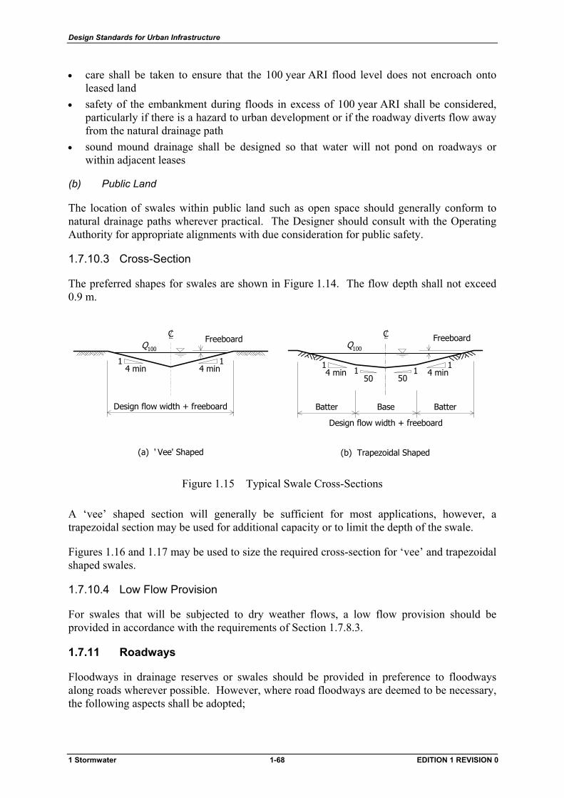
Design Standards for Urban Infrastructure
• care shall be taken to ensure that the 100 year ARI flood level does not encroach onto leased land
• safety of the embankment during floods in excess of 100 year ARI shall be considered, particularly if there is a hazard to urban development or if the roadway diverts flow away from the natural drainage path
• sound mound drainage shall be designed so that water will not pond on roadways or within adjacent leases
(b) Public Land
The location of swales within public land such as open space should generally conform to natural drainage paths wherever practical. The Designer should consult with the Operating Authority for appropriate alignments with due consideration for public safety.
1.7.10.3 Cross-Section
The preferred shapes for swales are shown in Figure 1.14. The flow depth shall not exceed 0.9 m.
15050
11
4 min14 min
Batter Base Batter
Q100
Design flow width + freeboard
(b) Trapezoidal Shaped
C FreeboardC
Design flow width + freeboard
4 min1 1
4 min
Q100
(a) ' Vee' Shaped
Freeboard
Figure 1.15 Typical Swale Cross-Sections
A ‘vee’ shaped section will generally be sufficient for most applications, however, a trapezoidal section may be used for additional capacity or to limit the depth of the swale.
Figures 1.16 and 1.17 may be used to size the required cross-section for ‘vee’ and trapezoidal shaped swales.
1.7.10.4 Low Flow Provision
For swales that will be subjected to dry weather flows, a low flow provision should be provided in accordance with the requirements of Section 1.7.8.3.
1.7.11 Roadways
Floodways in drainage reserves or swales should be provided in preference to floodways along roads wherever possible. However, where road floodways are deemed to be necessary, the following aspects shall be adopted;
1 Stormwater 1-68 EDITION 1 REVISION 0
Design Standards for Urban Infrastructure
• the flow characteristics of the ‘gap’ flow (refer to Section 1.7.3) shall not exceed the surface flow criteria limits specified in Table 1.15
• the catchment area feeding a road floodway shall be kept as small as possible. Conditions creating high water velocities and excessive water depths in a road floodway shall be avoided
• ready discharge from road floodways at low points or other relief points shall be provided to remove water quickly, avoid ponding, and prevent deposition of gravel and silt on the roadway
• a drainage reserve or open space area incorporating a designated overland flow path shall be provided on the downstream side of road low points. The overland flow path shall be sized for the 'gap' flow and located such that flows do not encroach onto leases A depressed kerb and verge may be required to limit the depth of ponding on the roadway
• the floodway cross-section and continuity shall be maintained to protect properties on the low side of roadways from inundation by flows overtopping verges. The high point of all low side road verges, including driveway entrances, shall be at least 50 mm above the 'gap' flow flood level
• materials used in the construction of medians, paths, verges, etc, shall be able to withstand inundation at anticipated design flow velocities. Pine bark, gravel and other loose materials shall not be used as they are likely to scour and cause blockage of inlet sumps
1.7.12 Roughness Coefficients
1.7.12.1 General
Care must be taken in the estimation of the waterway Manning ‘s roughness coefficient ‘n’. The choice of an appropriate value for the roughness coefficient of an engineered waterway is often critical in the overall design procedure and requires a considerable degree of judgement.
Suggested Manning's roughness coefficient values for the design of engineered waterways are provided in Table 1.33.
The Designer should use judgement in selecting an appropriate design value from the range of values given. However, the maximum and minimum values should be used to check the sensitivity of an engineered waterway to varying roughness value conditions as discussed in the following section.
1.7.12.2 Sensitivity Analyses
The Designer should ensure that the parameters adopted in the design of an engineered waterway system accurately represent the range of anticipated conditions that could reasonably be expected to occur throughout the design life of the waterway. The surface roughness of a waterway is dependent on a number of variables including vegetal type, time or season of year, and degree of maintenance.
The Designer shall assess the capacity of an engineered waterway for both the lowest and highest likely values of Manning’s roughness coefficient during the design life of the waterway. The lowest coefficient will give the highest velocity and therefore the most
1 Stormwater 1-69 EDITION 1 REVISION 0
Design Standards for Urban Infrastructure
critical situation in relation to waterway scour. The highest coefficient will give the lowest velocity and therefore the highest flood levels and the greatest likelihood of silt deposition.
1.7.12.3 Composite Waterways
Estimation of an equivalent or composite Manning’s roughness value in a waterway of varying roughness is required where there is a marked variation in the boundary roughness across an individual cross-section. Examples of this situation include a floodway containing a concrete low flow invert, or a waterway containing a low level footpath, cycleway or access track along the waterway.
The following equation may be used to estimate the overall roughness coefficient in engineered waterways of composite roughness;
∑=
=m
i ii
i
*
Pn
APA
n
13/2
3/5
3/2
3/5
where,
n* = equivalent Manning’s roughness coefficient for the whole cross-section ni = Manning's roughness coefficient for segment i A = flow area of whole cross-section (m2) Ai = flow area of segment i (m2) P = wetted perimeter of whole cross-section (m) Pi = wetted perimeter of segment i (m) m = total number of segments
It is important that the Designer check that the composite Manning’s roughness coefficient value is reasonable. A distorted or inaccurate value will result in inaccurate predictions of waterway flow conditions.
1.7.13 Erosion and Scour Protection
1.7.13.1 General
The design average flow velocity limits specified in Section 1.7.5.2 have been selected to prevent erosion and scour of waterway surfaces under normal conditions. However, waterways may be subject to intense local erosion or scour at obstructions (e.g. bridge piers, pipe headwalls), sudden changes in waterway cross-sections, drops, regions of changes in waterway bed materials and other similar conditions.
The following locations are the most common areas where localised erosion can occur and will require careful consideration of the need for erosion protection measures:
• Transitions : Any changes in cross-section or changes in waterway lining material. Particular attention should be paid to the region immediately alongside low flow inverts
• Bends : The outside bank of bends will be subject to higher flow velocities
1 Stormwater 1-70 EDITION 1 REVISION 0

Design Standards for Urban Infrastructure
• Branch pipelines : Waterways usually have many small capacity branch pipeline connections. Flows from these branch pipelines will normally be of relatively high velocity and the angle of entry will cause turbulence in the waterway
• Waterway tributaries : Other waterways entering the main waterway system may cause turbulence and erosion of the waterway bottom and opposing bank
• Energy dissipator structures : Changes in the flow regime will usually occur immediately upstream and downstream of drop structures and energy dissipation basins
• Culverts : Exit velocities from culvert crossings will normally be supercritical • Bridges and underpasses : Flow velocities around piers and abutments may be higher
than the waterway limit
Waterway protection must be provided to suit the local physical and scour characteristics. Erosion protection is required for engineered waterway linings in reaches where the maximum permissible average flow velocities specified in Table 1.15 or critical tractive forces are exceeded under 100 year ARI flow conditions.
Localised scour or general degradation can quickly lower the bottom of a channel. Erosion protection facilities must have deep toe protection to prevent failure by undermining.
1 Stormwater 1-71 EDITION 1 REVISION 0
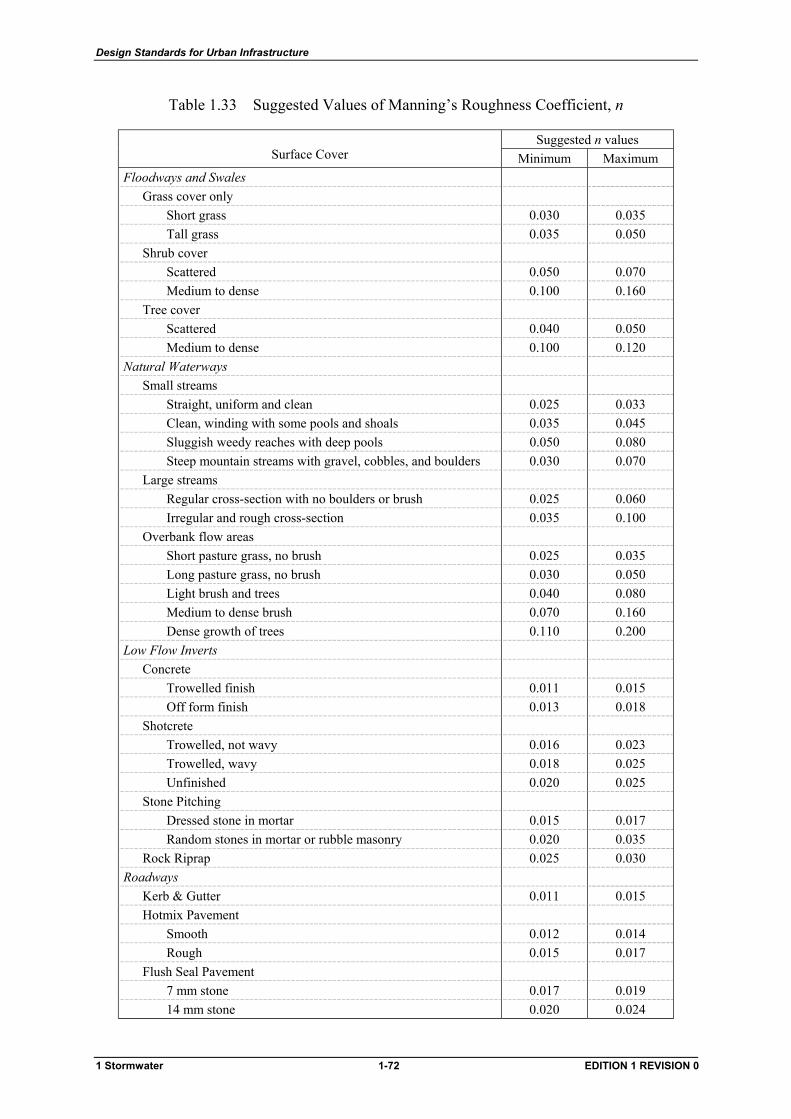
Design Standards for Urban Infrastructure
Table 1.33 Suggested Values of Manning’s Roughness Coefficient, n
Suggested n values Surface Cover Minimum Maximum
Floodways and Swales Grass cover only
Short grass 0.030 0.035 Tall grass 0.035 0.050
Shrub cover Scattered 0.050 0.070 Medium to dense 0.100 0.160
Tree cover Scattered 0.040 0.050 Medium to dense 0.100 0.120
Natural Waterways Small streams
Straight, uniform and clean 0.025 0.033 Clean, winding with some pools and shoals 0.035 0.045 Sluggish weedy reaches with deep pools 0.050 0.080 Steep mountain streams with gravel, cobbles, and boulders 0.030 0.070
Large streams Regular cross-section with no boulders or brush 0.025 0.060 Irregular and rough cross-section 0.035 0.100
Overbank flow areas Short pasture grass, no brush 0.025 0.035 Long pasture grass, no brush 0.030 0.050 Light brush and trees 0.040 0.080 Medium to dense brush 0.070 0.160 Dense growth of trees 0.110 0.200
Low Flow Inverts Concrete
Trowelled finish 0.011 0.015 Off form finish 0.013 0.018
Shotcrete Trowelled, not wavy 0.016 0.023 Trowelled, wavy 0.018 0.025 Unfinished 0.020 0.025
Stone Pitching Dressed stone in mortar 0.015 0.017 Random stones in mortar or rubble masonry 0.020 0.035
Rock Riprap 0.025 0.030 Roadways
Kerb & Gutter 0.011 0.015 Hotmix Pavement
Smooth 0.012 0.014 Rough 0.015 0.017
Flush Seal Pavement 7 mm stone 0.017 0.019 14 mm stone 0.020 0.024
1 Stormwater 1-72 EDITION 1 REVISION 0
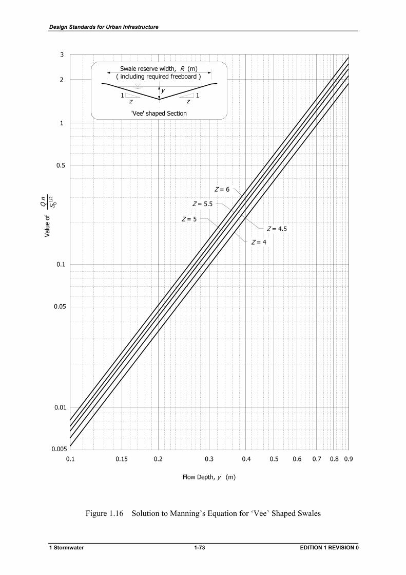
Design Standards for Urban Infrastructure
0.1 0.90.5
Flow Depth, y (m)
0.2 0.3 0.4 0.6 0.7 0.8
1
0.01
0.5
0.1
3
0.005
0.05
2
Valu
e of
Q n
S 01/
2
0.15
Z = 5.5
Z = 6
Z = 5
Z = 4.5
Z = 4
Swale reserve width, R (m)( including required freeboard )
y
z1
z1
'Vee' shaped Section
Figure 1.16 Solution to Manning’s Equation for ‘Vee’ Shaped Swales
1 Stormwater 1-73 EDITION 1 REVISION 0
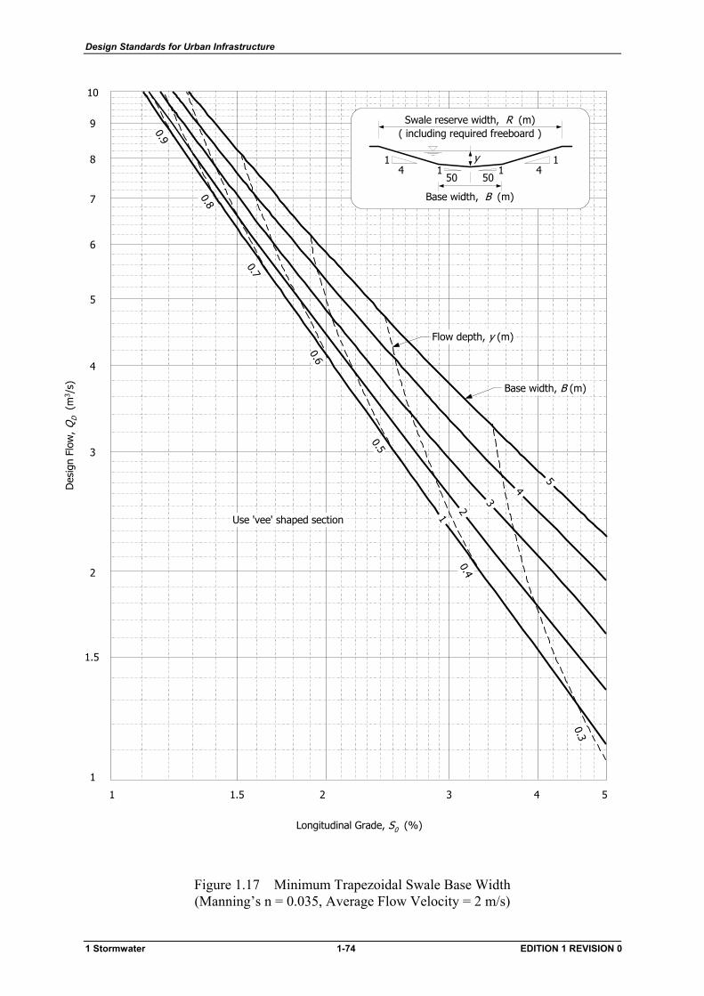
Design Standards for Urban Infrastructure
Longitudinal Grade, S0 (%)
1
10
1 52 3 4
2
3
4
5
6
7
8
9
Des
ign
Flow
, QD (
m3 /
s)
501 1
504
14
1
Base width, B (m)
Swale reserve width, R (m)( including required freeboard )
y
Base width, B (m)
Flow depth, y (m)
1.5
1.5
0.4
0.6
0.9
0.8
0.7
0.5
0.3
1
2
3
4
5
Use 'vee' shaped section
Figure 1.17 Minimum Trapezoidal Swale Base Width (Manning’s n = 0.035, Average Flow Velocity = 2 m/s)
1 Stormwater 1-74 EDITION 1 REVISION 0
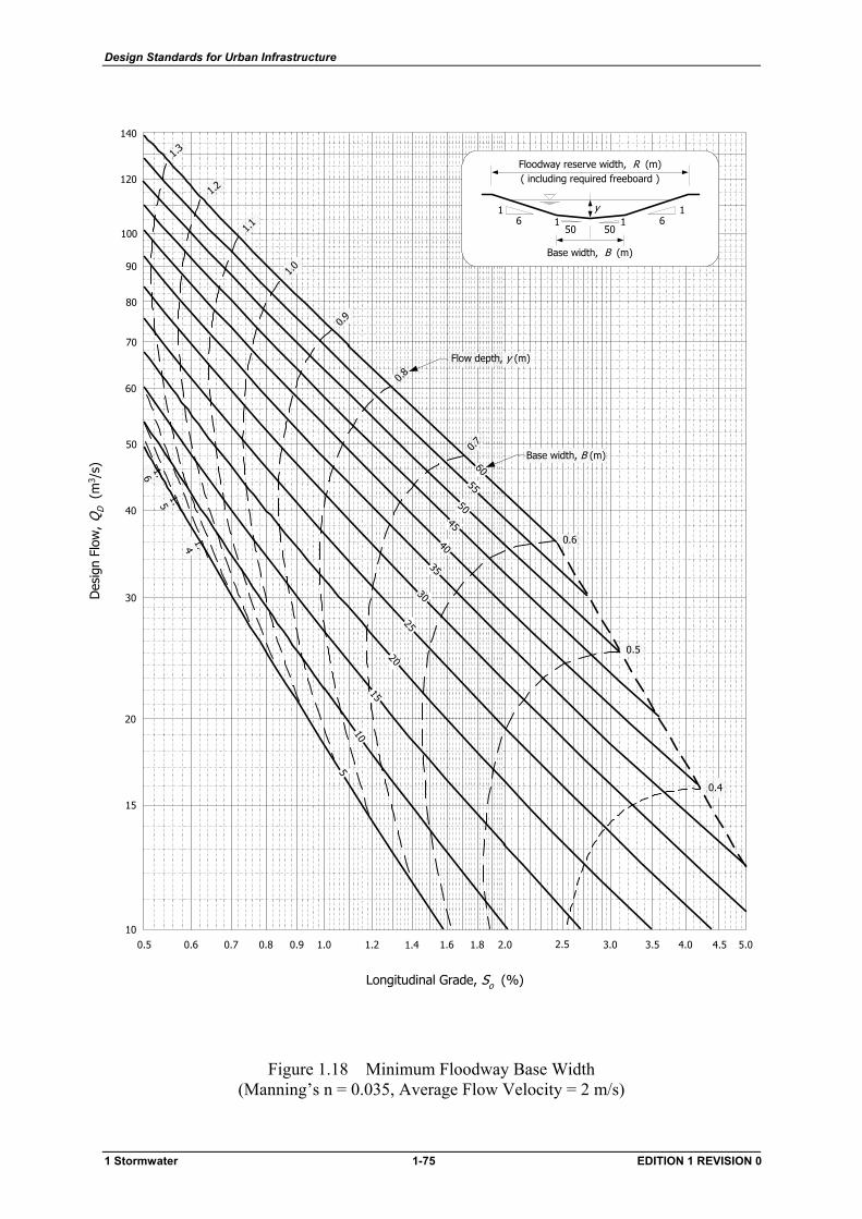
Design Standards for Urban Infrastructure
Des
ign
Flow
, Q
D (
m3 /
s)
0.4
0.6
1.2
1.3
1.41.5
1.6
1.1
1.0
0.9
0.8
0.7
Longitudinal Grade, So (%)
0.6 0.8 1.0 2.00.5 0.7 0.9 1.2 1.4 1.6 1.8 2.5 3.0 3.5 4.0 4.5 5.010
20
40
60
80
100
30
120
140
50
70
90
15
0.5
Flow depth, y (m)
1520
2530
35
5055
60
4045
10
5
Base width, B (m)
501 1
506
16
1
Base width, B (m)
Floodway reserve width, R (m)( including required freeboard )
y
Figure 1.18 Minimum Floodway Base Width (Manning’s n = 0.035, Average Flow Velocity = 2 m/s)
1 Stormwater 1-75 EDITION 1 REVISION 0
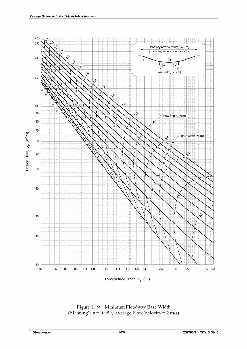
Design Standards for Urban Infrastructure
Des
ign
Flow
, Q
D (
m3 /
s)
150
200
270
10
20
40
60
80
100
30
50
70
90
15
2.0
1.5
1.7
1.9
1.2
1.1
1.0
0.9
0.8
0.7
0.6
0.5
1.3
1.4
1.8
1.6
2.1250
5
15
20
25
45
6055
50
40
35
30
10
Longitudinal Grade, So (%)
0.6 0.8 1.0 2.00.5 0.7 0.9 1.2 1.4 1.6 1.8 2.5 3.0 3.5 4.0 4.5 5.0
Base width, B (m)
Flow depth, y (m)
2.2
2.32.4
2.52.6
2.7
501 1
506
16
1
Base width, B (m)
Floodway reserve width, R (m)( including required freeboard )
y
Figure 1.19 Minimum Floodway Base Width (Manning’s n = 0.050, Average Flow Velocity = 2 m/s)
1 Stormwater 1-76 EDITION 1 REVISION 0
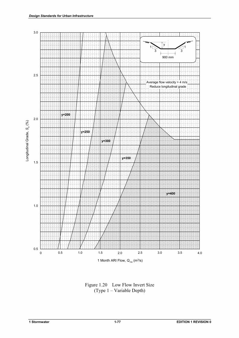
Design Standards for Urban Infrastructure
1.0
1.5
2.0
2.5
3.0
0.50.5 1.0 1.5 2.0 2.5 3.0 3.5 4.00
y=200
y=250
y=300
y=350
y=400
Average flow velocity > 4 m/sReduce longitudinal grade
31
900 mm
31
y
1 Month ARI Flow, Q1m (m3/s)
Long
itudi
nal G
rade
, So (
%)
Figure 1.20 Low Flow Invert Size (Type 1 – Variable Depth)
1 Stormwater 1-77 EDITION 1 REVISION 0
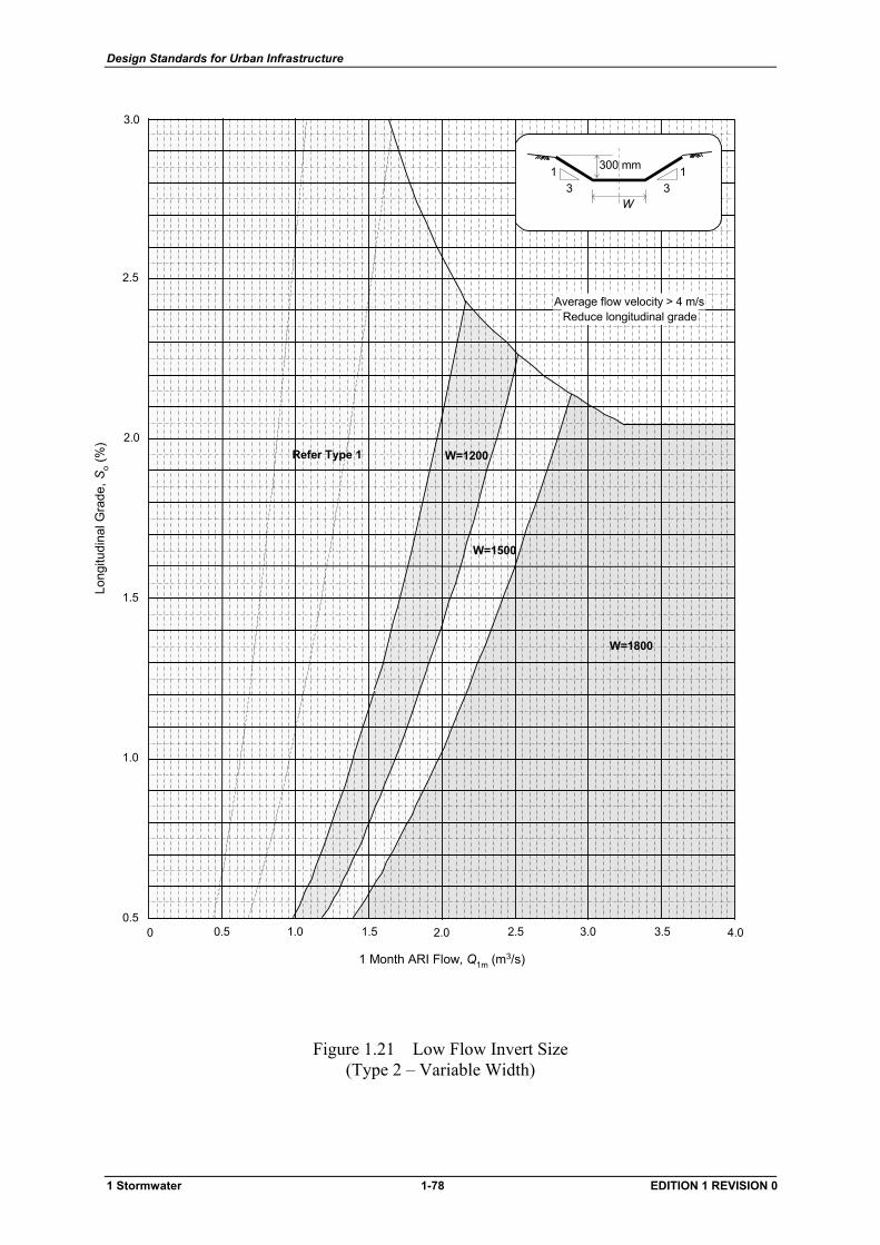
Design Standards for Urban Infrastructure
0.5 1.0 1.5 2.0 2.5 3.0 3.5 4.00
3.0
0.5
1.0
1.5
2.0
2.5
W=1800
W=1500
W=1200Refer Type 1
31
31300 mm
W
1 Month ARI Flow, Q1m (m3/s)
Long
itudi
nal G
rade
, So (
%)
Average flow velocity > 4 m/sReduce longitudinal grade
Figure 1.21 Low Flow Invert Size (Type 2 – Variable Width)
1 Stormwater 1-78 EDITION 1 REVISION 0
Design Standards for Urban Infrastructure
1.8 Cut-off Drains
1.8.1 General Requirements
Cut-off drains shall be provided to regulate surface runoff from public and unleased land adjacent to;
• road reserves • lease boundaries where the total uphill catchment is greater than 0.5 hectares
Cut-off drains shall be sized for flows up to and including 100 year ARI.
Cut-off drains shall divert surface runoff clear of leases and road reserves to discharge into the nearest natural watercourse, floodway, or overland flow path.
Cut-off drains should be located such that the area between the drain and lease boundaries which will contribute surface runoff directly to leases is minimised as far as practicable (refer to Figure 1.22).
Traversing of large natural gullies or major ridges is not desirable and will be permitted only when subject to special planning and design.
Cut-off drains are part of the urban edge zone and shall be considered in the context of the Design Standard 22 – Urban Edge Zone. The Operating Authority shall be consulted regarding landscape requirements in the vicinity of cut-off drains. Trees shall not be planted within the embankment zones of cut-off drains.
The management of the urban edge zone will generally incorporate a number of diverse functions other than protection of development from surface runoff. Designers should consider the total objectives of the edge zone and provide multi-functional facilities wherever possible.
1.8.1.1 Minor Drain
For small catchment areas, or in relatively flat terrain, it may be possible to utilise the access track as the cut-off drain to provide 100 year ARI flow capacity. Refer to Figure 1.22(a).
1.8.1.2 Major Drain
A separate cut-off drain must be provided wherever the cross sectional area of a cambered track is insufficient to provide 100 year ARI flow capacity. Refer to Figure 1.22(b).
1.8.2 Primary Outlets
Provision shall be made to discharge flows up to and including 100 year ARI.
Design flows shall normally be discharged to a designated overland flow path via an outlet pipe or a spillway chute. Discharge points shall be provided at intervals not exceeding 600 m.
1 Stormwater 1-79 EDITION 1 REVISION 0
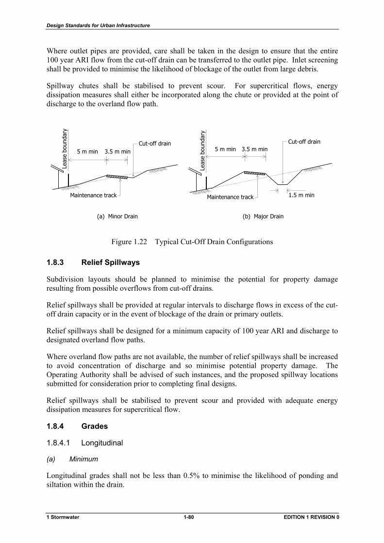
Design Standards for Urban Infrastructure
Where outlet pipes are provided, care shall be taken in the design to ensure that the entire 100 year ARI flow from the cut-off drain can be transferred to the outlet pipe. Inlet screening shall be provided to minimise the likelihood of blockage of the outlet from large debris.
Spillway chutes shall be stabilised to prevent scour. For supercritical flows, energy dissipation measures shall either be incorporated along the chute or provided at the point of discharge to the overland flow path.
1.5 m min
���
Cut-off drain
Maintenance track
5 m min
Leas
e bo
unda
ry
3.5 m min
(b) Major Drain
3.5 m min5 m min
���
Cut-off drain
Maintenance track
Leas
e bo
unda
ry
(a) Minor Drain
Figure 1.22 Typical Cut-Off Drain Configurations
1.8.3 Relief Spillways
Subdivision layouts should be planned to minimise the potential for property damage resulting from possible overflows from cut-off drains.
Relief spillways shall be provided at regular intervals to discharge flows in excess of the cut-off drain capacity or in the event of blockage of the drain or primary outlets.
Relief spillways shall be designed for a minimum capacity of 100 year ARI and discharge to designated overland flow paths.
Where overland flow paths are not available, the number of relief spillways shall be increased to avoid concentration of discharge and so minimise potential property damage. The Operating Authority shall be advised of such instances, and the proposed spillway locations submitted for consideration prior to completing final designs.
Relief spillways shall be stabilised to prevent scour and provided with adequate energy dissipation measures for supercritical flow.
1.8.4 Grades
1.8.4.1 Longitudinal
(a) Minimum
Longitudinal grades shall not be less than 0.5% to minimise the likelihood of ponding and siltation within the drain.
1 Stormwater 1-80 EDITION 1 REVISION 0
Design Standards for Urban Infrastructure
(b) Maximum
The maximum longitudinal grade shall be selected such that the average flow velocity in the drain does not exceed the following values under any operating conditions;
• 2 m/s for unlined drains • 4 m/s for lined drains
1.8.4.2 Side Slopes
The maximum side slopes of the cut-off drain invert section shall be;
• slope in fill 1 in 2 • slope in cut: earth 1 in 2
rock 1 in 0.25
1.8.5 Maintenance
1.8.5.1 Access Criteria
Cut-off drains shall be designed to allow for ease of maintenance, including ready access for maintenance machinery.
In general, cut-off drains shall be designed so that mechanical grass cutting equipment (ie. motor mowers or tractor mounted mowers) can be used to control grass and weed growth. Maintenance of the drain cross section should be possible using conventional earthmoving equipment such as backhoes, front-end loaders, and trucks.
Where conditions do not permit ready access, cut-off drains shall be designed for minimum maintenance by providing such measures as concrete lining or stone pitching of the drain.
1.8.5.2 Access Tracks
An all weather access track with a minimum width of 3.5 m shall be provided.
The access track shall be designed with the cross fall into the slope. The cross fall shall be within the following limits;
• 3% minimum • 10% maximum
The preferred location for the track is on top of the drain embankment. However, in some instances it may be preferable to locate the track on the downstream side of the embankment.
Adequate scour protection shall be provided for the track. For longitudinal gradients exceeding 10%, the track should be surfaced with one of the following;
• two coat seal • reinforced concrete • unit paving • bitumen stabilised decomposed granite gravel
1 Stormwater 1-81 EDITION 1 REVISION 0
Design Standards for Urban Infrastructure
Where access tracks have insufficient width to allow maintenance vehicles to pass, pull over bays shall be provided at a maximum spacing of 250 m.
1.8.5.3 Access Points from Urban Area
Access from the urban road network via feeder roads, culs-de-sac, pedestrian ways, or floodways shall be provided at intervals not exceeding 500 m.
Access points shall have a minimum width of 3.5 m to allow unconstrained access for maintenance vehicles. Structures should not be allowed to impinge on the access.
Provision shall be made to prevent access to the cut-off drain by unauthorised vehicles.
Hard surfacing shall be provided for access points steeper than 10% in accordance with Section 1.8.5.2.
1.8.5.4 Crossing Points
Crossing points may be required to gain access to areas above a cut-off drain. The Designer shall refer to the Operating Authority for the requirement and location of crossing points.
Generally, the crossing may be designed at-grade where side slopes are not steeper than 1 in 6. The crossing point shall be provided with a hard surface to delineate the point as a crossing, provide scour protection, and prevent damage to the embankment and drain by vehicles.
Where cross sectional side slopes are steeper than 1 in 6, the crossing should be formed using a culvert or bridge crossing with a minimum capacity of 100 year ARI. Adequate scour protection of the drain shall be provided on both sides of the culvert.
1.9 Retarding Basins
1.9.1 General
Retarding basins may be provided as an integral part of the major drainage system in new development areas to either;
• provide a more economic system by reducing downstream flow rates and waterway reserve widths, or
• meet a specific planning requirement that downstream flow rates not exceed pre-development values for both the minor and major system design ARI
It should be recognised that the provision of a retarding basin is only one method in a number of techniques available to manage stormwater runoff and therefore should be tested against other drainage strategies to arrive at the optimum solution to meet either of the above objectives.
The provision of retarding basins in the drainage system should be planned and designed as part of an overall catchment drainage strategy.
1 Stormwater 1-82 EDITION 1 REVISION 0
Design Standards for Urban Infrastructure
To gain maximum landuse benefit, retarding basins should be designed for multi-purpose use wherever possible. Recreational uses such as sporting fields and open space are considered most suitable. Sporting fields shall be provided with local drainage and a low flow by-pass for the minor drainage system.
1.9.2 Flow Control Requirements
Refer to Section 1.1.5 for general design flow control requirements for retarding basins.
Embankments shall be designed and constructed such that they will not breach under any operating conditions for all flows up to and including 100 year ARI. The maximum inundation period during the critical duration 100 year ARI design storm shall be 72 hours to prevent long term damage to grassed surfaces.
Retarding basins shall not cause floodwaters up to and including the 100 year ARI event to inundate upstream roads or leases.
1.9.3 Analysis
The Designer shall test the performance of the basin using a range of 'design' storms or a long term record of rainfall to determine the maximum storage requirements and the size of outlets for the basin.
A hydrograph estimation technique shall be used to estimate appropriate inflow hydrographs to the basin. Inflow hydrographs shall be routed through the basin using full reservoir routing calculations to determine the basin characteristics and resultant outflow hydrographs.
1.9.4 Outlet Design
1.9.4.1 Bypass Flows
Provision should be made in a retarding basin to bypass low flows through or around the basin. This is necessary to ensure that the basin floor, particularly if it is grassed, is not inundated by small storms or continually wetted by dry weather baseflow. The minimum amount of bypass shall be the 1 month ARI flow (refer to Section 1.7.8.3).
In existing areas, it may be desirable to bypass a larger amount than the 1 year ARI flow if a chosen site has insufficient capacity to attenuate both the minor and major system design storms. However, the level of flow bypassed should not exceed the downstream minor system design ARI. It should also be noted that the larger the amount of flow bypassed, the more difficult it will be to reduce the post-development minor system design flow to the pre-development level.
1.9.4.2 Primary Outlet
To achieve the general design flow control requirements specified in Section 1.1.5, the primary outlet configuration will generally consist of a multi-outlet structure or several outlet structures combined to provide multi-stage outlet control.
The outlet hydraulics for multi-outlet structures may be complicated and difficult to analyse. Care must be taken to ensure that the stage-discharge relationship adequately reflects the
1 Stormwater 1-83 EDITION 1 REVISION 0
Design Standards for Urban Infrastructure
range of different flow regimes that the structure will operate under. In some cases, particularly if the consequences of failure of the structure are high, the stage-discharge characteristics may need to be verified by physical modelling.
Primary outlets shall be designed to minimise the risk of blocking. The consequences of partial blockage of primary outlets shall be investigated and accounted for in the basin design if found to be significant.
Where a headwall or an open type structure is provided at the entrance to an outlet, an anti-vortex device should be considered to maximise hydraulic efficiency. The need for venting of the outlet should also be investigated.
1.9.4.3 Secondary Outlet
A secondary outlet to allow a non-catastrophic means of failure above the 100 year ARI event shall be provided. The most common outlet is a high-level weir crest and overflow spillway. Spillway design criteria shall be based on the Australian National Committee on Large Dams (ANCOLD) document, "Guidelines on Design Floods for Dams", 1986.
The spillway should be located at or adjacent to one of the embankment abutments to limit the possibility of embankment failure by scour.
1.9.5 Grades
Retarding basin embankment slopes shall have a maximum batter of 1 in 6. Slopes up to 1 in 4 may be approved in special circumstances.
The floor of the basin shall be designed with a minimum fall of 1 in 50 to provide positive drainage and minimise the likelihood of ponding.
1.9.6 Safety
It is inevitable that people will have access to a retarding basin, especially if it is designed for multi-purpose usage incorporating active or passive recreation, or sporting facilities. A retarding basin must be designed with public safety in mind both when the facility is in operation and also during periods between storms when the facility is empty. Appropriate ways must be considered to prevent and to discourage the public from being exposed to high-hazard areas during these periods.
The Designer must consider the following safety measures in the basin design;
• Provision of signs that clearly indicate the purpose and potential danger of a basin during storms. Signs should be located such that they are clearly visible at public access points and at entrances and exits to outlet structures.
• Gratings and trash racks at the inlet of a primary outlet structure. These should be inclined at an angle of 60o to the horizontal and placed a sufficient distance upstream of the inlet where the velocity through the rack is low. This should ensure that a person would not become held under the water against the grating or trash rack.
• Safety fencing on steep or vertical drops, such as headwalls and wingwalls, at the inlet and outlet to a primary outlet structure to discourage public access. Safety fencing can
1 Stormwater 1-84 EDITION 1 REVISION 0
Design Standards for Urban Infrastructure
also prevent a person inadvertently walking into or falling off these structures during periods when the basin is not in operation.
• Screening of outlet structures with bunds or shrubs to reduce their attraction potential to playing children or curious adults during periods that the basin is not in operation.
1.9.7 Erosion Protection
1.9.7.1 Primary Outlet
Consideration must be given to the need to protect the toe of the basin embankment and the bed and banks of the downstream waterway from erosion by high velocity outlet discharges.
For operating heads less than 1.8 m, a scour protection apron sized in accordance with Section 1.7.5.3(c) may only be required. For operating heads in excess of 1.8 m, an energy dissipating structure should be provided.
1.9.7.2 Embankment and Secondary Outlet
The surfaces of the embankment and secondary outlet (normally an overflow spillway) must also be protected against damage by scour when subject to high velocities. The degree of protection required depends on the velocity of flow, v, to which the bank will be subjected. The following treatments are recommended as a guide:
• v ≤ 3 m/s: a dense well-knit turf cover • 3 m/s < v < 7 m/s: a dense well-knit turf cover incorporating a turf reinforcement system • v ≥ 7 m/s: hard surfacing with concrete, riprap or similar
An open stilling basin may be required at the bottom of the spillway prior to discharge into the downstream waterway. It may be possible, and more cost effective, to provide a single stilling basin for both the secondary and primary basin outlets.
1.9.8 Landscaping
Retarding basins should be tastefully incorporated into the urban setting in which they reside. This is not a hydrologic consideration, but it is a consideration the community will use to judge these facilities. Aesthetics of the finished facility is therefore extremely important.
Wherever possible, designs should incorporate naturally shaped basins with landscaped banks, footpaths, and selective planting of vegetation to help enrich the area and provide a focal point for surrounding development. Sympathetic landscaping and the resulting improvement in local visual amenity will also encourage the public to accept retarding basins as an element of the urban natural environment and not as a target for vandalism.
Trees and shrubs shall not be planted on basin embankments as they may increase the danger of embankment failure by ‘piping’ along the line of the roots.
1.9.9 Maintenance
Retarding basins shall be provided with adequate access for maintenance machinery to remove silt or debris from the floor of the basin. Access for maintenance shall also be provided to the primary and secondary outlets.
1 Stormwater 1-85 EDITION 1 REVISION 0

Design Standards for Urban Infrastructure
1.10 Gross Pollutant Traps
1.10.1 General Requirements
Unless otherwise directed by the Planning Authority, gross pollutant traps (GPTs) shall be provided at the downstream end of pipelines and engineered waterways that discharge into water pollution control ponds (WQCPs), urban lakes and receiving waters (eg. Murrumbidgee River) whenever the catchment area of the pipeline or engineered waterway exceeds 8 hectares.
GPTs provide initial water pollution control for WQCPs and urban lakes by removing litter, debris and coarse sediment from stormwater. Most GPTs will also provide some reduction in other pollutants. For example, trapping of coarse sediment may also provide:
• removal of particulate nutrients • removal of trace metals, oil and grease • reduction in bacteria • reduction in dissolved oxygen demanding substances
All of the above substances can be partly bound to sediments, and will be removed along with the trapped sediment.
1.10.1.1 GPT Types
The most commonly used types of GPT in Canberra to date have been the ‘Minor GPT’ and the ‘Major GPT’ which consist of a concrete sediment basin with a fixed trash rack at the downstream end of the basin. However, in recent years there have been numerous proprietary devices developed for trapping gross solids that may be suitable for use in Canberra. To help distinguish Minor and Major GPTs from the newer proprietary traps available, the former shall now be referred to as Minor and Major DUS GPTs. The term GPT shall refer to any device designed to trap gross solids.
Selection of suitable devices depends on many factors including catchment size, pollutant load, type of drainage system and cost. Table 1.34 provides an overall classification of the types of GPT that may be permissible for use in Canberra, and the range of catchment areas for which they are suitable.
The Australian CRCCH (Co-operative Research Centre for Catchment Hydrology) markets a spreadsheet-based decision support system for GPTs. This may be of assistance in selecting the most suitable types of GPT.
Proposals for the use of GPT devices other than DUS GPTs shall be referred to the Operating Authority for consideration. Only devices capable of being maintained with conventional maintenance equipment will be considered.
1 Stormwater 1-86 EDITION 1 REVISION 0
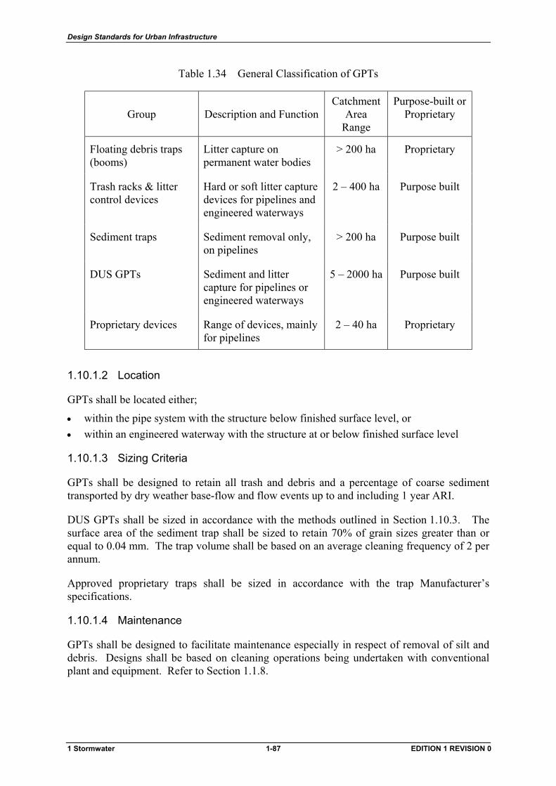
Design Standards for Urban Infrastructure
Table 1.34 General Classification of GPTs
Group Description and Function Catchment
Area Range
Purpose-built or Proprietary
Floating debris traps (booms)
Litter capture on permanent water bodies
> 200 ha Proprietary
Trash racks & litter control devices
Hard or soft litter capture devices for pipelines and engineered waterways
2 – 400 ha Purpose built
Sediment traps Sediment removal only, on pipelines
> 200 ha Purpose built
DUS GPTs Sediment and litter capture for pipelines or engineered waterways
5 – 2000 ha Purpose built
Proprietary devices Range of devices, mainly for pipelines
2 – 40 ha Proprietary
1.10.1.2 Location
GPTs shall be located either;
• within the pipe system with the structure below finished surface level, or • within an engineered waterway with the structure at or below finished surface level
1.10.1.3 Sizing Criteria
GPTs shall be designed to retain all trash and debris and a percentage of coarse sediment transported by dry weather base-flow and flow events up to and including 1 year ARI.
DUS GPTs shall be sized in accordance with the methods outlined in Section 1.10.3. The surface area of the sediment trap shall be sized to retain 70% of grain sizes greater than or equal to 0.04 mm. The trap volume shall be based on an average cleaning frequency of 2 per annum.
Approved proprietary traps shall be sized in accordance with the trap Manufacturer’s specifications.
1.10.1.4 Maintenance
GPTs shall be designed to facilitate maintenance especially in respect of removal of silt and debris. Designs shall be based on cleaning operations being undertaken with conventional plant and equipment. Refer to Section 1.1.8.
1 Stormwater 1-87 EDITION 1 REVISION 0
Design Standards for Urban Infrastructure
1.10.1.5 Dewatering
GPTs shall be designed to allow dewatering of supernatant water within the trap by gravity drainage or pumping to a downstream waterway or WQCP.
Dewatering facilities shall be;
• designed for ease of maintenance • screened to minimise the likelihood of pump or pipe blockage by sediment and debris • located such that maintenance equipment operating within the trap will not be obstructed
1.10.2 DUS GPT Design Requirements
1.10.2.1 Major DUS GPT
Major DUS GPTs shall conform to the general requirements of Standard Drawing ST-0033 and shall incorporate the following specific features;
(a) Trash Rack
• grill spacing shall be capable of retaining a 375 ml metal drink container • trash racks shall be sized to operate effectively during flows up to and including the
1 year ARI • trash racks shall be structurally stable when overtopped by flood events up to
100 year ARI or when fully blocked • trash racks shall be able to withstand impact from a piece of debris weighing 500 kg and
travelling at 3.0 m/s • trash racks shall conform to Standard Drawing ST-0034 • panel widths may be either 2.8 m or 4.8 m
(b) Sediment Trap
• the minimum plan dimensions of the trap shall be 6 m x 12 m • the trap shall be dimensioned such that the length to width ratio is between 2 and 3 and
the width is a multiple of 3.0 m or 5.0 m. The width shall be sized for a minimum of two trash rack panels
• a base-flow bypass shall be provided around the sediment trap and trash rack to facilitate access for cleaning. The bypass shall operate under gravity and have a minimum capacity of 1.5 l/s per km2 of catchment area
• a sediment drying area with a minimum area equal to 1.5 m2 for each cubic metre of trap volume shall be provided. The area shall be surfaced with 300 mm of compacted gravel
• the sediment trap floor shall be graded to a low point to facilitate dewatering of the trap • the width of base-flow discharge over the trash rack weir wall and dowstream apron shall
be kept to a minimum, preferably confined within a single trash rack panel • the minimum level of the top of the trash rack side wall returns shall be the greater of the
1 year ARI flow level in the sediment trap when the trash rack is fully blocked or 300 mm above the top of the trash rack. The top of the return walls shall slope upward from the trash rack to finished ground level at a minimum slope of 1 in 10
• side walls shall be keyed into original ground for a minimum depth of 300mm
1 Stormwater 1-88 EDITION 1 REVISION 0
Design Standards for Urban Infrastructure
(c) Access
• access shall be provided for cleaning by mechanical equipment such as front end loaders, back hoes, and tip trucks. The access shall be a separate all-weather track and ramp designed for a 7 tonne wheel load in a W-7 configuration in accordance with the AUSTROADS Bridge Code. Where possible, trucks should be able to drive within close proximity to where the loader is operating
• the access track to the trap shall have a minimum clear width of 3.7 m and a maximum longitudinal grade of 1 in 6
• the access ramp into the sediment trap shall have a minimum clear width of 6.0 m and a maximum longitudinal grade of 1 in 6. The 6.0 m clear width shall extend from the floor of the trap to the end of the side wall returns. Where the length of a trap is less than or equal to 15.0 m, the access ramp shall extend for the entire length of the trap
• an access ramp and apron shall also be provided for the downstream side of the trash rack and shall have a minimum clear width of 4.0 m and a maximum longitudinal grade of 1 in 6
• transitions shall be provided at the crest and toe of the ramps. Adequate space shall also be provided to allow vehicles to manoeuvre on and off the ramps
(d) Public safety
Public safety shall be considered and the following minimum safeguards shall be provided;
• hand rails at vertical drops where appropriate • maximum side slopes adjacent to side walls shall be 1 in 6
1.10.2.2 Minor DUS GPT
Minor DUS GPTs shall conform to the general requirements of Standard Drawing ST-0032 and shall incorporate the following specific features;
(a) Trash Rack
• grill spacing shall be capable of retaining a 375 ml metal drink container • trash racks shall be sized to operate effectively during flows up to and including the
1 year ARI • trash racks shall be structurally stable when overtopped by flows up to the total inlet
design capacity or when fully blocked • trash racks shall be able to withstand impact from a piece of debris weighing 250 kg and
travelling at 2.0 m/s • trash racks shall conform to Standard Drawing ST-0034 • the standard panel width shall be 1.9 m
(b) Sediment Trap
• the width shall be 2.0 m • the allowable length shall be in multiples of 2.0 m within the following limits,
minimum length: 4.0 m maximum length: 12.0 m
1 Stormwater 1-89 EDITION 1 REVISION 0
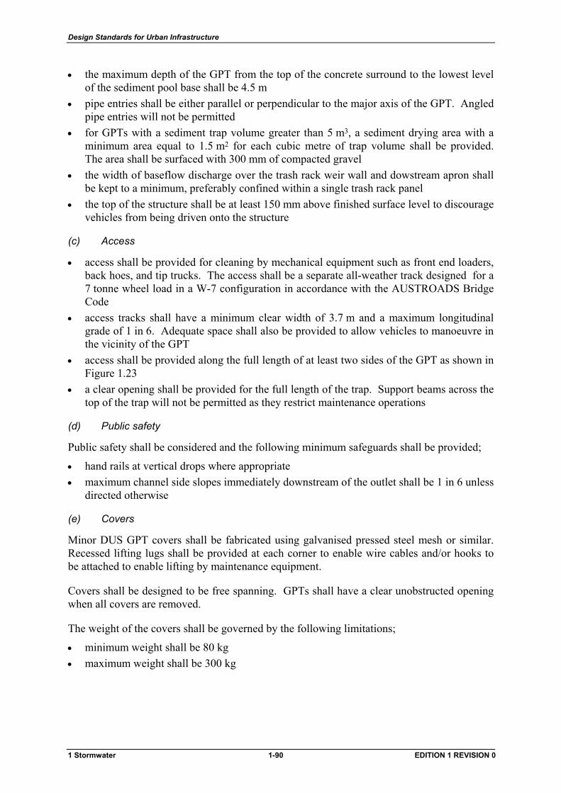
Design Standards for Urban Infrastructure
• the maximum depth of the GPT from the top of the concrete surround to the lowest level of the sediment pool base shall be 4.5 m
• pipe entries shall be either parallel or perpendicular to the major axis of the GPT. Angled pipe entries will not be permitted
• for GPTs with a sediment trap volume greater than 5 m3, a sediment drying area with a minimum area equal to 1.5 m2 for each cubic metre of trap volume shall be provided. The area shall be surfaced with 300 mm of compacted gravel
• the width of baseflow discharge over the trash rack weir wall and dowstream apron shall be kept to a minimum, preferably confined within a single trash rack panel
• the top of the structure shall be at least 150 mm above finished surface level to discourage vehicles from being driven onto the structure
(c) Access
• access shall be provided for cleaning by mechanical equipment such as front end loaders, back hoes, and tip trucks. The access shall be a separate all-weather track designed for a 7 tonne wheel load in a W-7 configuration in accordance with the AUSTROADS Bridge Code
• access tracks shall have a minimum clear width of 3.7 m and a maximum longitudinal grade of 1 in 6. Adequate space shall also be provided to allow vehicles to manoeuvre in the vicinity of the GPT
• access shall be provided along the full length of at least two sides of the GPT as shown in Figure 1.23
• a clear opening shall be provided for the full length of the trap. Support beams across the top of the trap will not be permitted as they restrict maintenance operations
(d) Public safety
Public safety shall be considered and the following minimum safeguards shall be provided;
• hand rails at vertical drops where appropriate • maximum channel side slopes immediately downstream of the outlet shall be 1 in 6 unless
directed otherwise
(e) Covers
Minor DUS GPT covers shall be fabricated using galvanised pressed steel mesh or similar. Recessed lifting lugs shall be provided at each corner to enable wire cables and/or hooks to be attached to enable lifting by maintenance equipment.
Covers shall be designed to be free spanning. GPTs shall have a clear unobstructed opening when all covers are removed.
The weight of the covers shall be governed by the following limitations;
• minimum weight shall be 80 kg • maximum weight shall be 300 kg
1 Stormwater 1-90 EDITION 1 REVISION 0
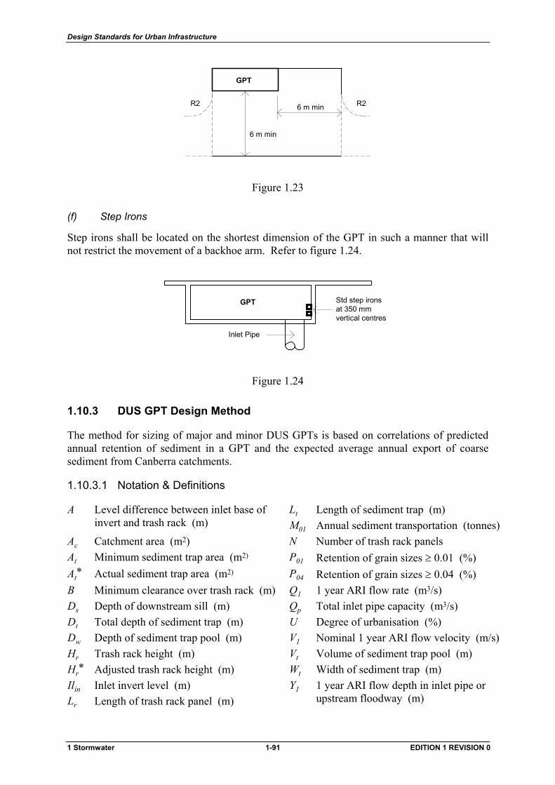
Design Standards for Urban Infrastructure
6 m min
6 m min
GPT
R2R2
Figure 1.23
(f) Step Irons
Step irons shall be located on the shortest dimension of the GPT in such a manner that will not restrict the movement of a backhoe arm. Refer to figure 1.24.
Std step ironsat 350 mmvertical centres
Inlet Pipe
GPT
Figure 1.24
1.10.3 DUS GPT Design Method
The method for sizing of major and minor DUS GPTs is based on correlations of predicted annual retention of sediment in a GPT and the expected average annual export of coarse sediment from Canberra catchments.
1.10.3.1 Notation & Definitions
A Level difference between inlet base of invert and trash rack (m)
Lt
M01 Length of sediment trap (m) Annual sediment transportation (tonnes)
Ac Catchment area (m2) N Number of trash rack panels At Minimum sediment trap area (m2) P01 Retention of grain sizes ≥ 0.01 (%) At* Actual sediment trap area (m2) P04 Retention of grain sizes ≥ 0.04 (%) B Minimum clearance over trash rack (m) Q1 1 year ARI flow rate (m3/s) Ds Depth of downstream sill (m) Qp Total inlet pipe capacity (m3/s) Dt Total depth of sediment trap (m) U Degree of urbanisation (%) Dw Depth of sediment trap pool (m) V1 Nominal 1 year ARI flow velocity (m/s) Hr Trash rack height (m) Vt Volume of sediment trap pool (m) Hr* Adjusted trash rack height (m) Wt Width of sediment trap (m) Ilin
Lr Inlet invert level (m) Length of trash rack panel (m)
Y1 1 year ARI flow depth in inlet pipe or upstream floodway (m)
1 Stormwater 1-91 EDITION 1 REVISION 0
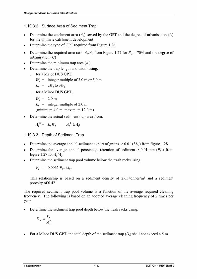
Design Standards for Urban Infrastructure
1.10.3.2 Surface Area of Sediment Trap
• Determine the catchment area (Ac) served by the GPT and the degree of urbanisation (U) for the ultimate catchment development
• Determine the type of GPT required from Figure 1.26
• Determine the required area ratio At /Ac from Figure 1.27 for P04 = 70% and the degree of urbanisation (U)
• Determine the minimum trap area (At) • Determine the trap length and width using,
for a Major DUS GPT,
Wt = integer multiple of 3.0 m or 5.0 m Lt = 2Wt to 3Wt
for a Minor DUS GPT,
Wt = 2.0 m Lt = integer multiple of 2.0 m (minimum 4.0 m, maximum 12.0 m)
• Determine the actual sediment trap area from,
At* = Lt Wt (At* ≥ At)
1.10.3.3 Depth of Sediment Trap
• Determine the average annual sediment export of grains ≥ 0.01 (M01) from figure 1.28 • Determine the average annual percentage retention of sediment ≥ 0.01 mm (P01) from
figure 1.27 for At /Ac • Determine the sediment trap pool volume below the trash racks using,
Vt = 0.0065 P01 M01
This relationship is based on a sediment density of 2.65 tonnes/m3 and a sediment porosity of 0.42.
The required sediment trap pool volume is a function of the average required cleaning frequency. The following is based on an adopted average cleaning frequency of 2 times per year.
• Determine the sediment trap pool depth below the trash racks using,
*t
tw A
VD =
• For a Minor DUS GPT, the total depth of the sediment trap (Dt) shall not exceed 4.5 m
1 Stormwater 1-92 EDITION 1 REVISION 0
Design Standards for Urban Infrastructure
1.10.3.4 Trash Rack
(a) Number of Panels
• Determine the number of trash rack panels (N) required based on the following centre to centre panel dimensions;
3.0 m or 5.0 m (Major DUS GPT)
2.0 m (Minor DUS GPT)
(b) Height
Generally, the trash rack height is based on the rack not being overtopped by a 1 year ARI flow when the rack is 50% blocked.
The following is based on a standard trash rack with vertical 10 mm galvanised flat steel bars at 60 mm centres. A coefficient of 0.8 to account for contraction of flow through the trash rack has been assumed.
• Determine the trash rack height using, for a Major DUS GPT,
3/2
122.1
=
NxLQHr
r
for a Minor DUS GPT,
Hr = 0.3 m (Q1 ≤ 0.23 N ) Hr = 0.5 m ( 0.23 N < Q1 ≤ 0.50 N ) Hr = 0.7 m (Q1 > 0.50 N )
Where a trash rack is easily accessible, the height shall be increased for public safety to,
Hr* = 1.2 m
• Determine the maximum trash rack sill level in relation to the 1 year ARI flow depth (Y1) and the inlet invert level (ILin) using,
for a Major DUS GPT,
1
3/2
1
7.1Y
WQHA
tr −
+=
for a Minor DUS GPT,
1
3/21
23.3Y
NQHA r −
+=
1 Stormwater 1-93 EDITION 1 REVISION 0
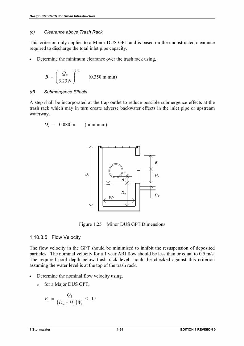
Design Standards for Urban Infrastructure
(c) Clearance above Trash Rack
This criterion only applies to a Minor DUS GPT and is based on the unobstructed clearance required to discharge the total inlet pipe capacity.
• Determine the minimum clearance over the trash rack using,
3/2
23.3
=
NQ
B p (0.350 m min)
(d) Submergence Effects
A step shall be incorporated at the trap outlet to reduce possible submergence effects at the trash rack which may in turn create adverse backwater effects in the inlet pipe or upstream waterway.
Ds = 0.080 m (minimum)
A
B
D w D s
H r t D
W t
in IL
Figure 1.25 Minor DUS GPT Dimensions
1.10.3.5 Flow Velocity
The flow velocity in the GPT should be minimised to inhibit the resuspension of deposited particles. The nominal velocity for a 1 year ARI flow should be less than or equal to 0.5 m/s. The required pool depth below trash rack level should be checked against this criterion assuming the water level is at the top of the trash rack.
• Determine the nominal flow velocity using,
for a Major DUS GPT,
( ) 5.011 ≤
+=
trw WHDQ
V
1 Stormwater 1-94 EDITION 1 REVISION 0

Design Standards for Urban Infrastructure
for a Minor DUS GPT,
( ) 5.011 ≤
+=
trw LHDQ
V
• Increase the dimensions of the sediment trap pool or increase the track rack height if the flow velocity is greater than 0.5 m/s
1 Stormwater 1-95 EDITION 1 REVISION 0
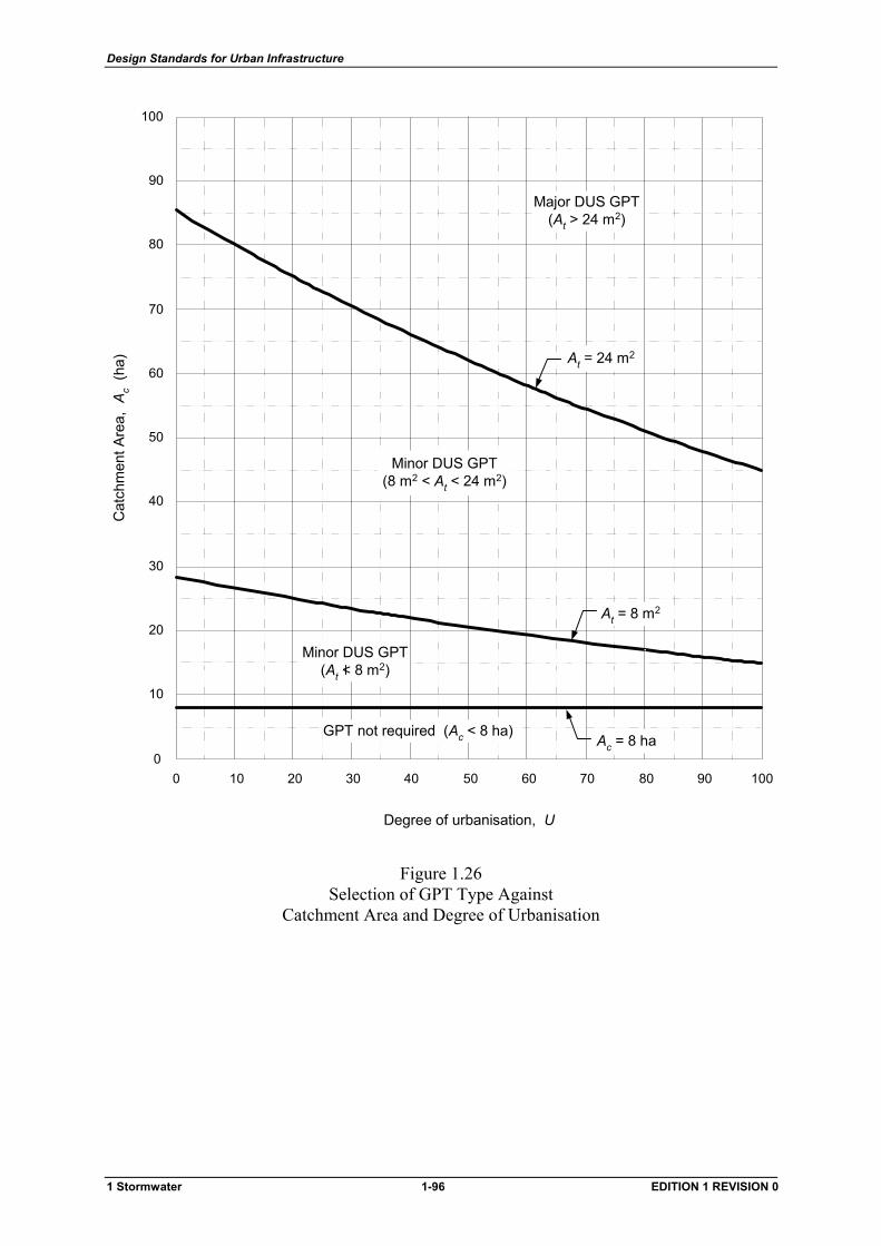
Design Standards for Urban Infrastructure
10 20 30 40 50 60 70 80 90 1000
10
20
30
40
50
60
70
80
90
100
0
Degree of urbanisation, U
Cat
chm
ent A
rea,
Ac
(ha)
U
GPT not required (Ac < 8 ha)Ac = 8 ha
Minor DUS GPT(8 m2 < At < 24 m2)
Major DUS GPT(At > 24 m2)
At = 8 m2
At = 24 m2
Minor DUS GPT(At < 8 m2)
Figure 1.26 Selection of GPT Type Against
Catchment Area and Degree of Urbanisation
1 Stormwater 1-96 EDITION 1 REVISION 0
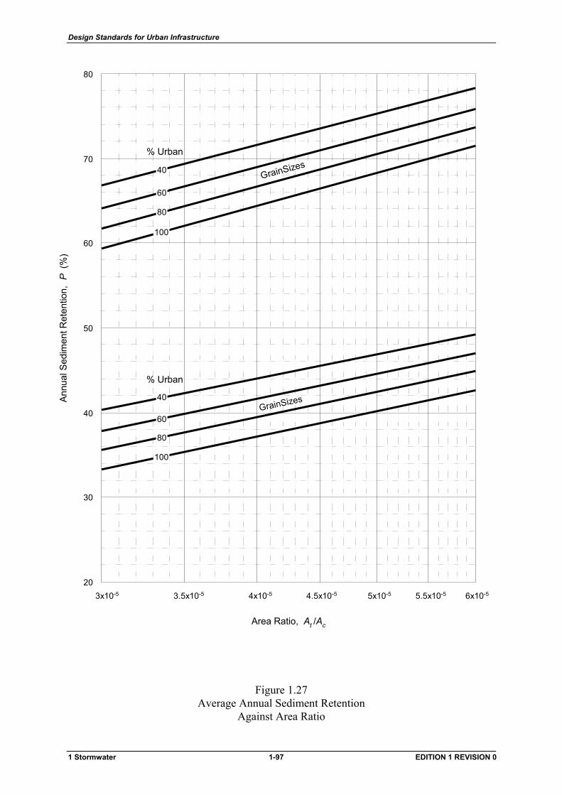
Design Standards for Urban Infrastructure
3x10⁻⁵ 4x10⁻⁵ 5x10⁻⁵ 6x10-55.5x10-54.5x10-53.5x10-5
Area Ratio, At /Ac
80
20
40
70
50
30
60
Annu
al S
edim
ent R
eten
tion,
P (
%)
% Urban
40
60
80
100
% Urban
40
60
80
100
ssssssssesesesesi esi esSi esSi esSi esSi esSizesSizesSizesSizesSizesSizesSizesSizesSizesSizesSizesSizesSizesSizesSizesSizesSizesSizesi Sizesi Sizesi Sizesi Sizesi SizesinSizesinSizesinSizesinSizesinSizesinSizesinSizesinSizesinSizeinSizeinSizeG inSizeG ainSizeG ainSizeG ainSizeG ainSizeG ainSizeG ainSizG ainSizG ainSizGrainSizGrainSizGrainSizGrainSizGrainSizGrainSiGrainSiGrainSiGrainSGrainSGrainSGrainSGrainSGrainSGrainSGrainSGrainSGrainSGrainSGrainSGrainGrainGrainGrainGrainGrainGrainGrainGraiGraiGraiGraiGraGraGraGraGraGraGraGraGraGraGrGrGrGrGGGGGGGGGGGGGGG
ssssssssssesesesesesesesesi esi esi esi esSizesSizesSizesSizesSizesSizesSizesSizesSizesSizesSizesSizesSizesSizesSizesSizesSizesSizesSizesSizesSizesSizesSizesSizesSizesSizesSizesi Sizesi Sizesi SizesinSizesinSizeinSizeinSizeinSizeinSizeinSizeinSizeinSizeinSizeinSizeinSizeinSizinSizinSizinSizainSizainSizainSizainSiz
G ainSizG ainSizG ainSiG ainSiG ainSiG ainSiG ainSGrainSGrainSGrainSGrainSGrainSGrainSGrainSGrainSGrainSGrainSGrainSGrainSGrainSGrainSGrainSGrainGrainGrainGrainGrainGrainGrainGrainGrainGrainGraiGraiGraiGraiGraiGraGraGraGraGraGraGraGraGraGraGraGraGraGrGrGrGrGrGrGGGGGGGGGGGGGGGGGG
Figure 1.27 Average Annual Sediment Retention
Against Area Ratio
1 Stormwater 1-97 EDITION 1 REVISION 0
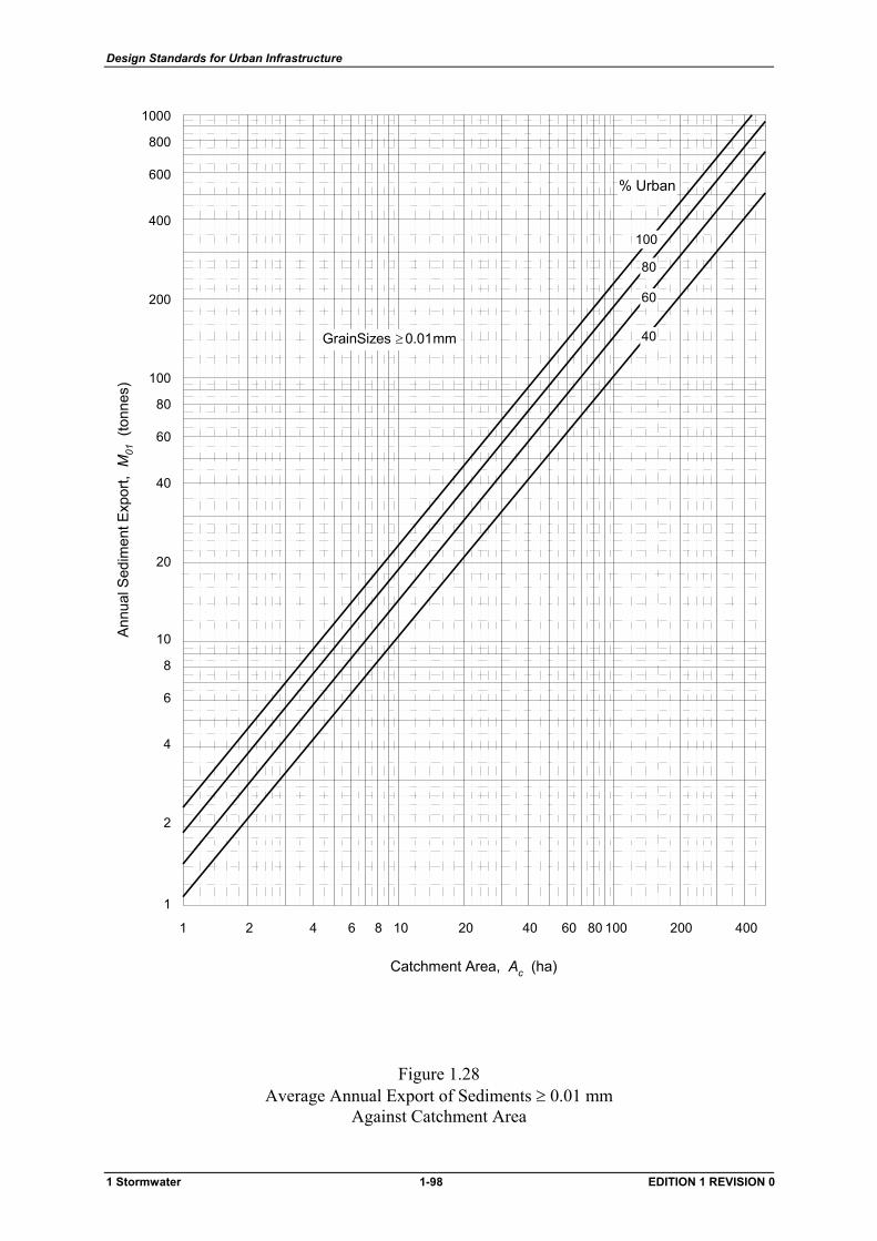
Design Standards for Urban Infrastructure
Catchment Area, Ac (ha)
1 2 4 6 8 10 20 40 60 80 100 200 400
Annu
al S
edim
ent E
xpor
t, M
01 (
tonn
es)
1
2
4
6
8
10
20
40
60
80
100
200
400
600
800
1000
% Urban
40
60
80
100
mm0.01GrainSizes ≥
Figure 1.28 Average Annual Export of Sediments ≥ 0.01 mm
Against Catchment Area
1 Stormwater 1-98 EDITION 1 REVISION 0
Design Standards for Urban Infrastructure
1.11 Further reading
Guidelines for Design Floods for Dams, ANCOLD. 1986
Storm Drainage Design in Small Urban Catchments: a handbook for Australian practice Australian Road Research Board, Special Report No.34, Argue J.
A comparative Analysis of Alternative Stormwater Systems in Australia, Concrete Pipe Association of Australia, prepared by WP Research, Final Report, June 1990.
Drainage Design Practice - Part 2, Department of Urban Services, prepared by Willing & Partners Pty Ltd, July 1992 (Draft).
Energy Losses in Pipe Systems, Advances in Urban Drainage Design, Hare C. M., Insearch Ltd, NSW Institute of Technology, 1981.
Pressure Changes at Storm Drain Junctions, Sangster W. M. J., Wood H. W., Smerdon E. T., University of Missouri.
Drainage Design Practice for Land Development in the ACT - Part 1: Rational Formula Procedures, National Capital Development Commission. , prepared by Willing & Partners Pty Ltd, January 1989.
Pressure Changes at Storm Drain Junctions', Engineering Series, Bulletin No. 41, Sangster W. M., Wood H. W., Smerdon E. T. and Bossy H. G. Engineering Experimental Station, University of Missouri, 1958.
Engineered Waterway Design Guidelines, Scott & Furphy Pty Ltd. July 1989 (Draft).
Car Stability on Road Floodways, Technical Report No. 73/12. University of NSW, Water Research Laboratory.
Low Level Causeways, Report No. 100 University of NSW, Water Research Laboratory.
ACT Floodplain Protection Policies and Guidelines, Interim Territory Planning Authority, October 1989.
1 Stormwater 1-99 EDITION 1 REVISION 0

Design Standards for Urban Infrastructure
1.12 Standard Drawings
TITLE NUMBER REV DATE
Pipe Junctions ST-0001 02 March 1998
Pipe Details ST-0002 02 March 1998
Sump Inlets on Kerbs and Gutters ST-0011 04 March 1998
Type R and QS Sumps ST-0012 02 March 1998
Plantation and Grated Sumps ST-0013 02 March 1998
1050 ND Manholes ST-0014 02 March 1998
Special Chambered Manholes ST-0015 02 March 1998
Surcharge Structures ST-0016 02 March 1998
Structures - Miscellaneous Details ST-0017 02 March 1998
Pipe Connections to Structures ST-0018 02 March 1998
Multiple Type R Sumps ST-0019 01 March 2002
Pipe Culverts 300 - 675 Dia - Endwalls ST-0021 02 March 1998
Pipe Culverts 750 - 1200 Dia - Headwalls ST-0022 02 March 1998
Precast Box Culverts - Endwalls ST-0023 02 March 1998
Precast Box Culverts - Headwalls ST-0024 02 March 1998
Floodway Low Flow Provisions ST-0025 02 March 1998
At-Grade Floodway Crossings ST-0026 02 March 1998
Minor GPT Layout - Parallel to Floodway ST-0031 02 March 1998
Minor GPT Layout - Perpendicular to Floodway ST-0032 02 March 1998
Major GPT Layout ST-0033 02 March 1998
GPT Trash Racks ST-0034 02 March 1998
Floodway Advisory Sign ST-0041 02 March 1998
1 Stormwater 1-100 EDITION 1 REVISION 0
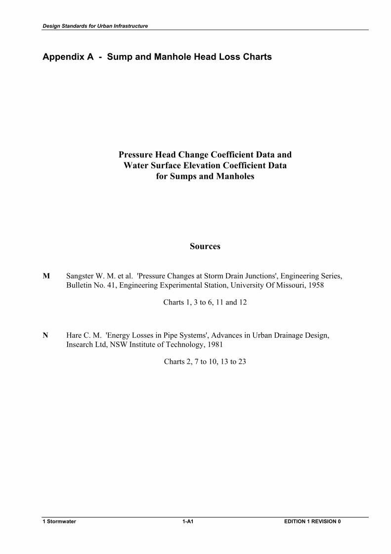
Design Standards for Urban Infrastructure
Appendix A - Sump and Manhole Head Loss Charts
Pressure Head Change Coefficient Data and Water Surface Elevation Coefficient Data
for Sumps and Manholes
Sources
M Sangster W. M. et al. 'Pressure Changes at Storm Drain Junctions', Engineering Series, Bulletin No. 41, Engineering Experimental Station, University Of Missouri, 1958
Charts 1, 3 to 6, 11 and 12
N Hare C. M. 'Energy Losses in Pipe Systems', Advances in Urban Drainage Design, Insearch Ltd, NSW Institute of Technology, 1981
Charts 2, 7 to 10, 13 to 23
1 Stormwater 1-A1 EDITION 1 REVISION 0
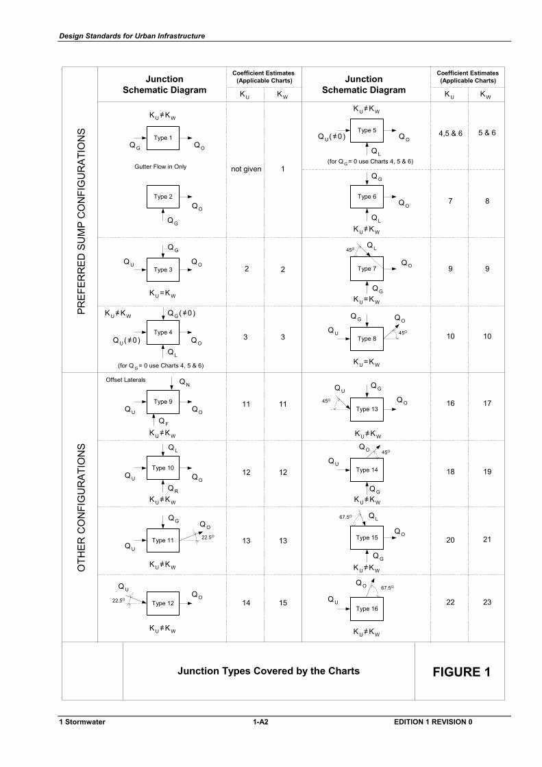
Design Standards for Urban Infrastructure
Type 7
Type 8
Type 13
Type 16
Type 15
Type 14
Type 9
Type 3
Type 2
Type 4
Type 1
FIGURE 1Junction Types Covered by the Charts
23221514
2120
12 1918
171611
1313
10103
9922
87
4,5 & 6
1not given
Offset Laterals
Gutter Flow in Only
(for Q G = 0 use Charts 4, 5 & 6)
(Applicable Charts)Coefficient Estimates
JunctionSchematic Diagram
Type 10
Type 11
Type 12
Type 5
Type 6
5 & 6
3
11
12
(Applicable Charts)Coefficient Estimates
JunctionSchematic Diagram
PREF
ERR
ED S
UM
P C
ON
FIG
UR
ATIO
NS
OTH
ER C
ON
FIG
UR
ATIO
NS
QOQ G
QO
QG
QO
QG
QU
QO
QG (=0)/
QU(=0)/QL
/KU=KW
KU=KW
/KU=KW
QO
QF
/KU=KW
QU
QN
QL
QOQU
QR
/KU=KW
/KU=KW
QG Q O
QU
22.5O
22.5OQO
Q U
/KU=KW
67.5OQO
Q U
/KU=KW
67.5O
QO
Q G
/KU=KW
QL
45OQO
QG/KU=KW
Q U
45O Q O
QG
/KU=KW
QU
QOQ G
Q U
KU=KW
45O
QO
QG
QL
KU=KW
45O
Q O
QG
QL
/KU=KW
/KU=KW
(for Q G = 0 use Charts 4, 5 & 6)
Q O
QL
Q U(=0)/
KU KWKU KW
1 Stormwater 1-A2 EDITION 1 REVISION 0
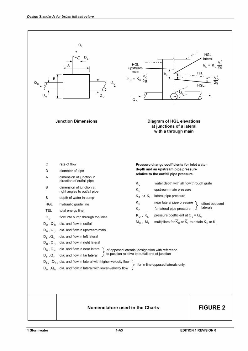
Design Standards for Urban Infrastructure
FIGURE 2Nomenclature used in the Charts
Junction Dimensions
B
A
QL
HGL
TEL
HGLlateral
Diagram of HGL elevationsat junctions of a lateral
with a through main
HGLupstream
main
relative to the outfall pipe pressure.depth and an upstream pipe pressurePressure change coefficients for inlet water
pressure coefficient at Q L = QO
far lateral pipe pressure
near lateral pipe pressure
lateral pipe pressure
upstream main pressure
water depth with all flow through grate
lateralsoffset opposed
flow into sump through top inlet
rate of flowQ
direction of outfall pipedimension of junction in
diameter of pipeD
A
depth of water in sump
right angles to outfall pipedimension of junction atB
S
of opposed laterals; designation with reference
dia. and flow in lateral with lower-velocity flow
dia. and flow in lateral with higher-velocity flow
dia. and flow in far lateral
dia. and flow in near lateral
dia. and flow in right lateral
dia. and flow in left lateral
dia. and flow in upstream main
dia. and flow in outfall
for in-line opposed laterals only
to position relative to outfall end of junction
hydraulic grade lineHGL
total energy lineTEL
D L
QU
D U
QO
DOQO
QL
hLhU
QG
DO ,QO
DU ,QU
DL ,QL
DN ,QN
DF ,QF
Dh v ,Qh v
D l v ,Q l v
DR ,QR
KG
KU
KR or KL
KN
KF
MU , ML multipliers for KU or KL to obtain KU or KL
KU , KL
hU = KU 2gVO
2
hL = KL 2gVO
2
2gVO
2
1 Stormwater 1-A3 EDITION 1 REVISION 0
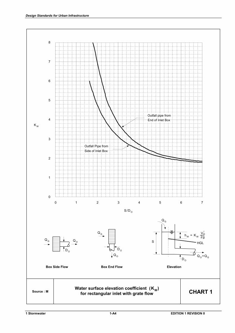
Design Standards for Urban Infrastructure
Water surface elevation coefficient (KW)for rectangular inlet with grate flowSource : M CHART 1
S/D O
Box End FlowBox Side Flow
QOQ G
D O
QO
QG
D O
Elevation
HGL
QG
QO =QGDO
hW = KW 2gOV2
S
76543210
0
1
2
3
4
5
6
7
8
End of Inlet BoxOutfall pipe from
Side of Inlet BoxOutfall Pipe from
KW
1 Stormwater 1-A4 EDITION 1 REVISION 0
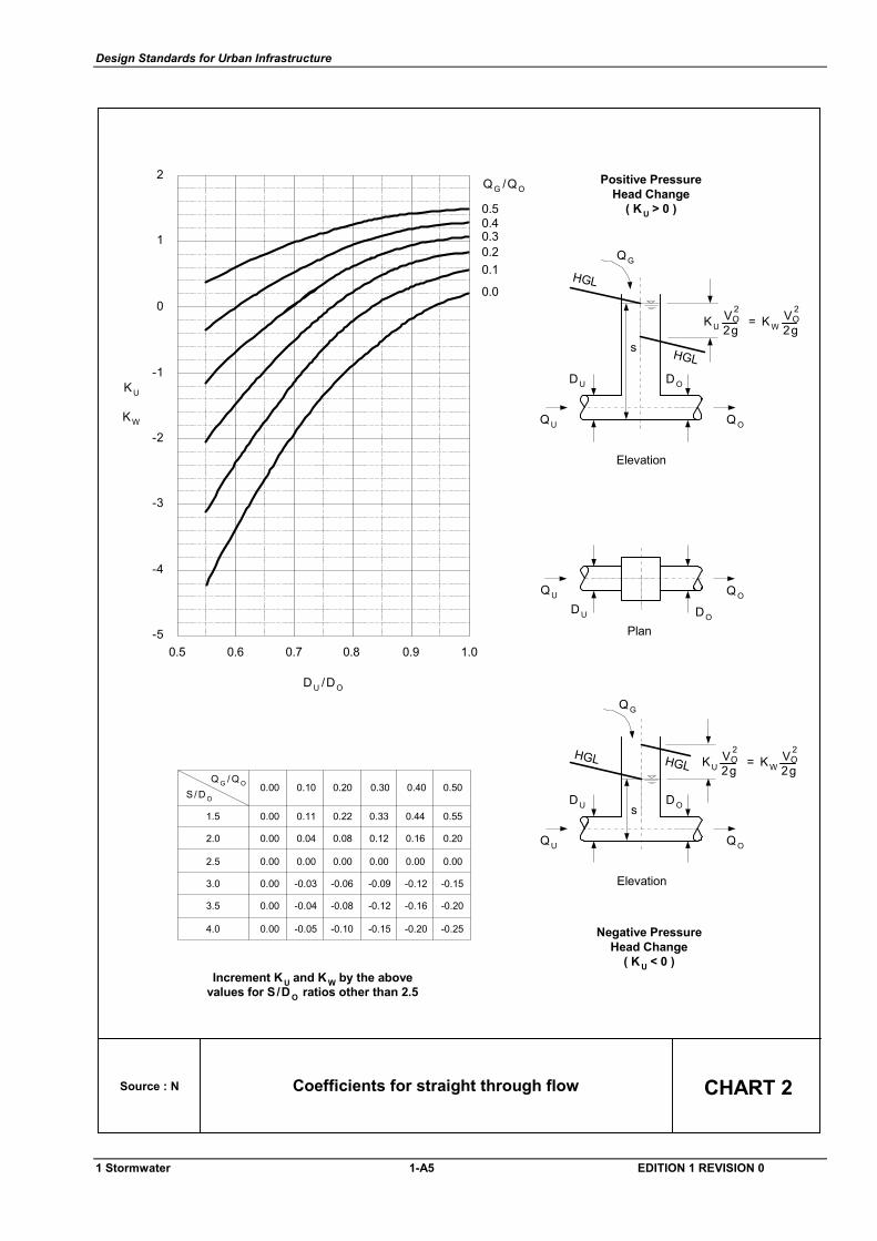
Design Standards for Urban Infrastructure
Source : N CHART 2Coefficients for straight through flow
0.50.40.30.20.1
0.0
1.00.90.80.70.60.5-5
-4
-3
-2
1
0
1
2QG /QO
KW
KU
D U /DO
-
Increment KU and K W by the abovevalues for S/D O ratios other than 2.5
0.00
0.00
0.00
0.00
0.00
0.00
0.11
0.04
0.00
-0.03
-0.04
-0.05
0.22
0.08
0.00
-0.06
-0.08
-0.10
0.33
0.12
0.00
-0.09
-0.12
-0.15
0.44
0.16
0.00
-0.12
-0.16
-0.20
0.55
0.20
0.00
-0.15
-0.20
-0.25
1.5
2.0
2.5
3.0
3.5
4.0
0.00 0.10 0.20 0.30 0.40 0.50S / D O
Q G / Q O
s
Elevation
QG
KU = KW 2gOV 2
2gOV 2
Negative PressureHead Change
( K U < 0 )
HGLHGL
Plan
QU Q O
Positive PressureHead Change
( K U > 0 )
s
Elevation
QG
KU = KW 2gOV 2
2gOV 2
HGL
HGL
D U DO
QU
D U D O
Q O
QU
D U D O
Q O
1 Stormwater 1-A5 EDITION 1 REVISION 0
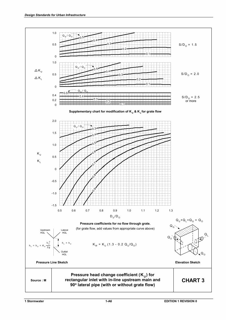
Design Standards for Urban Infrastructure
Pressure coefficients for no flow through grate.(for grate flow, add values from appropriate curve above)
OutfallHGL
Pressure Line Sketch Elevation Sketch
Source : M CHART 3
Supplementary chart for modification of KU & K Lfor grate flow
0.4
0.20
1.0
0
0.5
0.5
0
1.0
S/D O = 1 .5
KU
-1.5
-1.0
-0.5
0
0.5
1.0
1.5
2.0
DU/DO
QL
Q O
Q G / Q O
0.1
0.30.4
0.5
0.2
S/D O = 2 .0
S/D O = 2 .5or more
h L = h U = K U 2 g
V O2
LateralHGL
UpstreamHGL
h L = h U
Pressure head change coefficient (KU) forrectangular inlet with in-line upstream main and
90o lateral pipe (with or without grate flow)
Q U
QG
QU+QL+QG = QO
KW = KU (1.3 - 0.2 QU/QO )
Q G / Q O
0.1
0.30.4
0.5
0.2
Q G / Q O
0.10.3
0.4
0.2
0.5
0.5 0.6 0.7 0.8 0.9 1.0 1.1 1.2 1.3
KL
KU
KL
Q U / Q O
0.7
0.3
0.4
0.5
0.6
0.90.8
1 Stormwater 1-A6 EDITION 1 REVISION 0
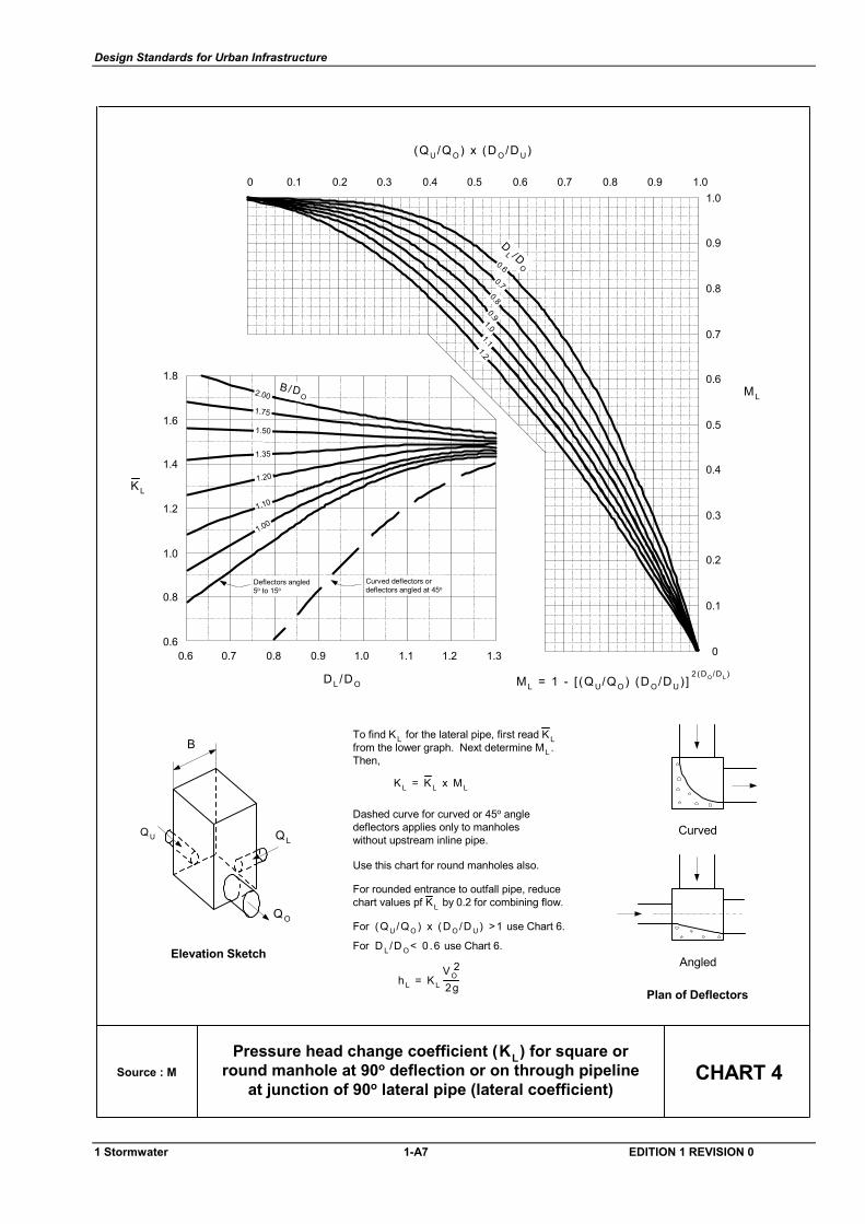
Design Standards for Urban Infrastructure
Source : M CHART 4Pressure head change coefficient (KL) for square or
round manhole at 90o deflection or on through pipelineat junction of 90o lateral pipe (lateral coefficient)
B
Elevation Sketch
Q U Q L
QO
1.31.21.11.00.90.80.7
1.8
1.6
1.4
1.2
1.0
0.8
0.60.6
1.00.90.80.70.60.50.40.30.20.101.0
0.9
0.8
0.7
0.6
0.5
0.4
0.3
0.2
0.1
0
Curved deflectors ordeflectors angled at 45o
Deflectors angled5o to 15o
B /DO2.00
1.75
1.50
1.35
1.20
1.10
1.00
0.60.7
0.80.9
1.11.2
1.0
DL /DO
KL
DL /D
O
(QU/QO ) x (D O/D U)
ML
2 (DO /D L )ML = 1 - [ (Q U/QO ) (D O/DU) ]
Use this chart for round manholes also.
Dashed curve for curved or 45o angledeflectors applies only to manholeswithout upstream inline pipe.
For (Q U /Q O ) x (D O /D U ) >1 use Chart 6.
For D L /D O < 0 .6 use Chart 6.
To find K L for the lateral pipe, first read K Lfrom the lower graph. Next determine ML .Then,
For rounded entrance to outfall pipe, reducechart values pf KL by 0.2 for combining flow.
K L = K L x M L
h L = K L 2gVO
2
Plan of Deflectors
Angled
Curved
1 Stormwater 1-A7 EDITION 1 REVISION 0
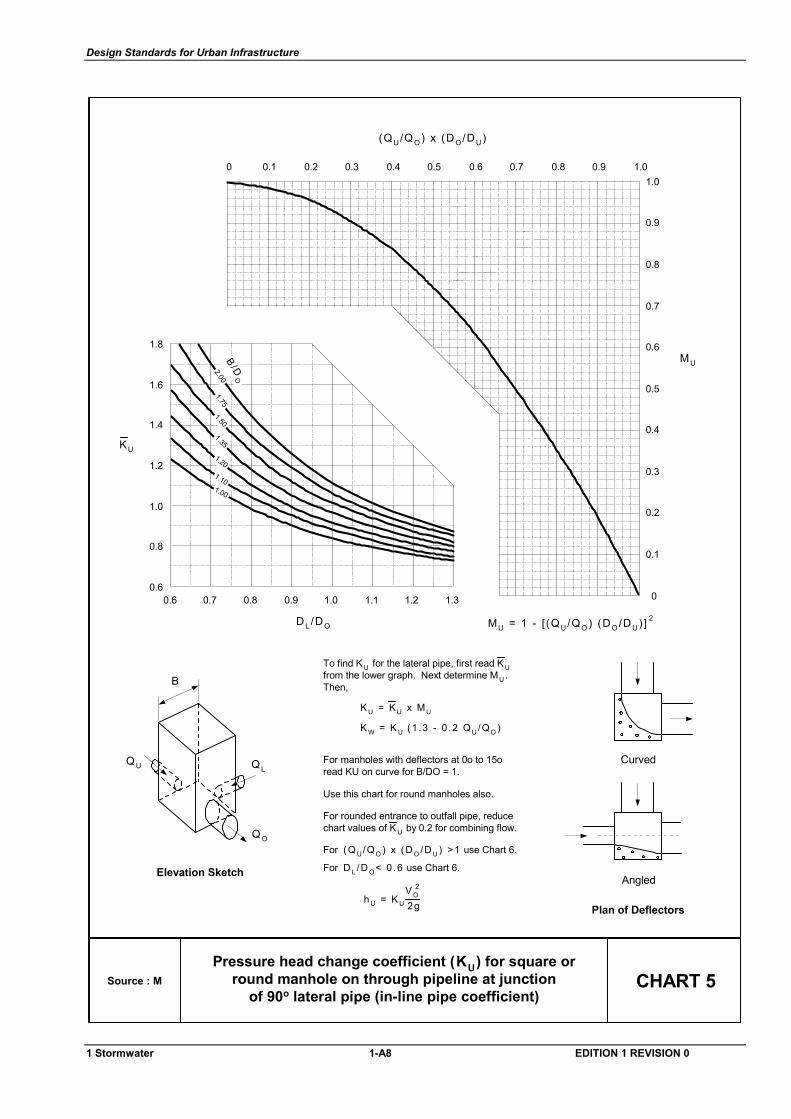
Design Standards for Urban Infrastructure
Source : M CHART 5Pressure head change coefficient (KU) for square or
round manhole on through pipeline at junctionof 90o lateral pipe (in-line pipe coefficient)
1.31.21.11.00.90.80.7
1.8
1.6
1.4
1.2
1.0
0.8
0.60.6
1.00.90.80.70.60.50.40.30.20.101.0
0.9
0.8
0.7
0.6
0.5
0.4
0.3
0.2
0.1
0
D L /D O
KU
(QU/QO ) x (D O/DU)
MU
1.00
1.10
1.20
1.35
1.501.75
2.00B /D
O
MU = 1 - [ (QU/QO ) (DO /DU) ] 2
B
Elevation Sketch
QU QL
QO
To find KU for the lateral pipe, first read K Ufrom the lower graph. Next determine MU .Then,
K U = KU x MU
K W = K U ( 1 .3 - 0 .2 Q U/Q O )
For manholes with deflectors at 0o to 15oread KU on curve for B/DO = 1.
Use this chart for round manholes also.
For (Q U/Q O ) x (D O /D U ) >1 use Chart 6.
For D L /D O < 0 .6 use Chart 6.
For rounded entrance to outfall pipe, reducechart values of KU by 0.2 for combining flow.
h U = K U 2gVO
2
Plan of Deflectors
Angled
Curved
1 Stormwater 1-A8 EDITION 1 REVISION 0
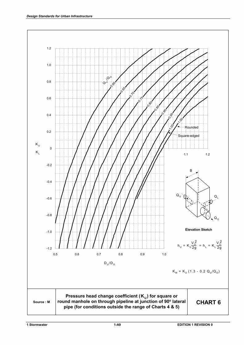
Design Standards for Urban Infrastructure
Source : M CHART 6
2gVO
2 = hL = KL
KW = KU (1.3 - 0.2 QU/Q O)
Pressure head change coefficient (KU) for square orround manhole on through pipeline at junction of 90o lateral
pipe (for conditions outside the range of Charts 4 & 5)
B
Elevation Sketch
QU QL
QO
1.21.1
1.00.90.80.70.60.5
KU
DU/DO
KL
hU = KU 2gVO
2
1.2
1.0
0.6
0.4
0.2
0
-0.2
-0.4
-0.6
-0.8
-1.0
-1.2
0.8 Q U/Q
O0.6
0
0.65
0.70
0.75
0.80
0.85
0.90
0.95
1.00
1.00
Square-edged
Rounded
1 Stormwater 1-A9 EDITION 1 REVISION 0
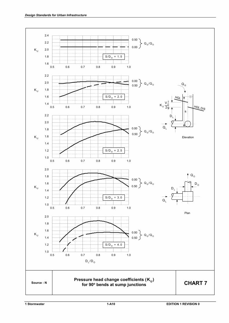
Design Standards for Urban Infrastructure
Source : N CHART 7
Plan
QL
Q O
D O
DL
Pressure head change coefficients (KU)for 90o bends at sump junctions
2.0
1.6
1.8
2.4
2.2
0.5 0.6 0.7 0.8 0.9 1.0
S/D O = 1 .5
Q G /Q O
0.50
0.00KU
1.4
1.0
1.2
1.8
1.6
0.5 0.6 0.7 0.8 0.9 1.0
Q G /Q O0.50
0.00
KU
2.0
S/D O = 3 .0
1.4
1.0
1.2
1.8
1.6
0.5 0.6 0.7 0.8 0.9 1.0
Q G /Q O0.50
0.00KU
2.0
S/D O = 4 .0
DL /DO
1.8
1.4
1.6
2.2
2.0
0.5 0.6 0.7 0.8 0.9 1.0
S/D O = 2 .0
Q G /Q O0.500.00
KU
1.4
1.0
1.2
1.8
1.6
0.5 0.6 0.7 0.8 0.9 1.0
Q G /Q O0.50
0.00
KU
2.0
2.2
S/D O = 2 .5
s
Elevation
HGL D/S
HGL
QL
QG
KU 2gVO
2
D L
1 Stormwater 1-A10 EDITION 1 REVISION 0
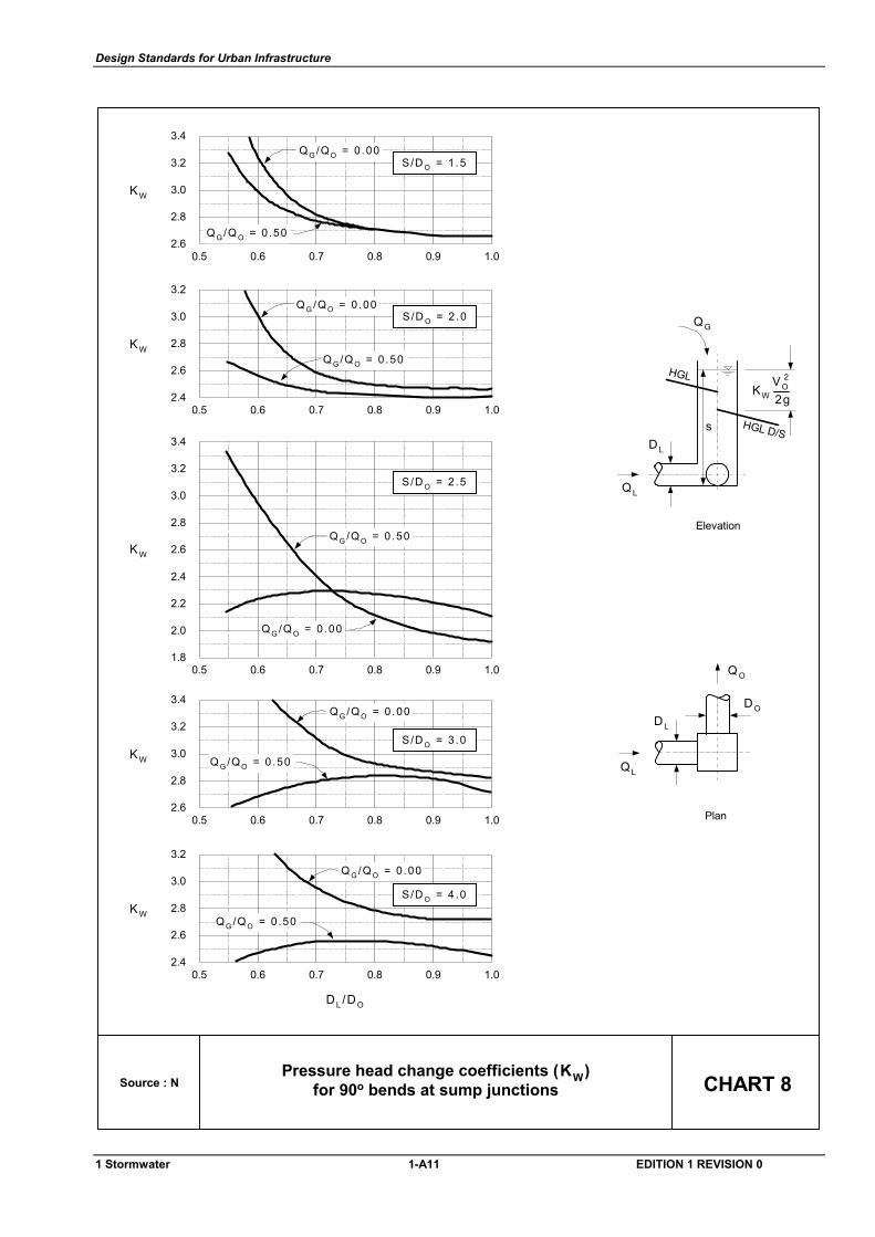
Design Standards for Urban Infrastructure
2.8
2.4
2.6
3.2
3.0
0.5 0.6 0.7 0.8 0.9 1.0
S/D O = 4 .0KW
DL /DO
Q G /Q O = 0 .50
Q G /Q O = 0 .00
3.0
2.6
2.8
3.4
3.2
0.5 0.6 0.7 0.8 0.9 1.0
S/D O = 3 .0KW Q G /Q O = 0 .50
Q G /Q O = 0 .00
Source : N CHART 8
s
Elevation
HGL D/S
HGL
QL
QG
Plan
QL
Q O
D O
DL
Pressure head change coefficients (KW)for 90o bends at sump junctions
KW 2gVO
2
3.0
2.6
2.8
3.4
3.2
0.5 0.6 0.7 0.8 0.9 1.0
S/D O = 1 .5
KW
Q G /Q O = 0 .50
Q G /Q O = 0 .00
2.8
2.4
2.6
3.2
3.0
0.5 0.6 0.7 0.8 0.9 1.0
S/D O = 2 .0
KW
Q G /Q O = 0 .00
Q G /Q O = 0 .50
2.6
2.2
2.4
3.0
2.8
KW
3.2
3.4
0.5 0.6 0.7 0.8 0.9 1.01.8
2.0 Q G /Q O = 0 .00
Q G /Q O = 0 .50
S/D O = 2 .5
D L
1 Stormwater 1-A11 EDITION 1 REVISION 0
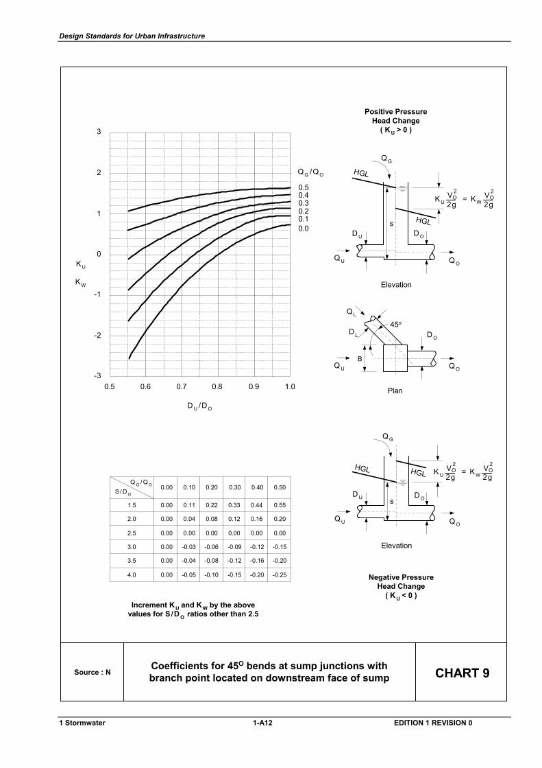
Design Standards for Urban Infrastructure
Source : N CHART 9Coefficients for 45O bends at sump junctions withbranch point located on downstream face of sump
0.50.40.30.20.10.0
1.00.90.80.70.60.5-3
-2
-1
0
1
2
3
QG /QO
KW
KU
D U /DO
Increment KU and K W by the abovevalues for S/D O ratios other than 2.5
0.00
0.00
0.00
0.00
0.00
0.00
0.11
0.04
0.00
-0.03
-0.04
-0.05
0.22
0.08
0.00
-0.06
-0.08
-0.10
0.33
0.12
0.00
-0.09
-0.12
-0.15
0.44
0.16
0.00
-0.12
-0.16
-0.20
0.55
0.20
0.00
-0.15
-0.20
-0.25
1.5
2.0
2.5
3.0
3.5
4.0
0.00 0.10 0.20 0.30 0.40 0.50S / D O
Q G / Q O
s
Elevation
HGLHGL
QG
KU = KW 2gOV 2
2gOV 2
Negative PressureHead Change
( K U < 0 )
Positive PressureHead Change
( KU > 0 )
s
Elevation
HGL
HGL
QG
KU = KW 2gOV 2
2gOV 2
Plan
QU Q O
QL
DL
B
45o
D O
D U D O
Q OQU
D U D O
Q OQU
1 Stormwater 1-A12 EDITION 1 REVISION 0
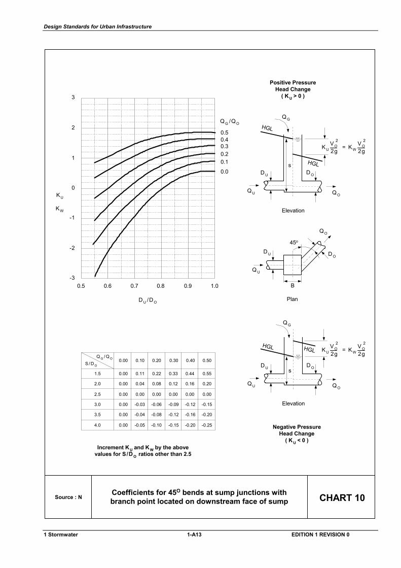
Design Standards for Urban Infrastructure
Source : N CHART 10Coefficients for 45O bends at sump junctions withbranch point located on downstream face of sump
0.50.40.30.20.1
0.0
1.00.90.80.70.60.5-3
-2
-1
0
1
2
3
QG /QO
KW
KU
D U /DO
Increment KU and K W by the abovevalues for S/D O ratios other than 2.5
0.00
0.00
0.00
0.00
0.00
0.00
0.11
0.04
0.00
-0.03
-0.04
-0.05
0.22
0.08
0.00
-0.06
-0.08
-0.10
0.33
0.12
0.00
-0.09
-0.12
-0.15
0.44
0.16
0.00
-0.12
-0.16
-0.20
0.55
0.20
0.00
-0.15
-0.20
-0.25
1.5
2.0
2.5
3.0
3.5
4.0
0.00 0.10 0.20 0.30 0.40 0.50S / D O
Q G / Q O
s
Elevation
HGLHGL
QG
Negative PressureHead Change
( K U < 0 )
Positive PressureHead Change
( KU > 0 )
s
Elevation
HGL
HGL
QG
Plan
Q U
QO
DU
B
DO
45o
D U D O
Q OQU
D U D O
Q OQU
KU = KW 2g2gVO
2VO2
KU = KW 2g2gVO
2VO2
1 Stormwater 1-A13 EDITION 1 REVISION 0
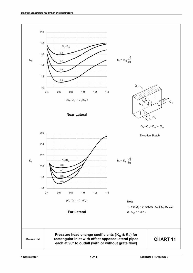
Design Standards for Urban Infrastructure
CHART 11Source : M
0.6
0.7
0.8
1.41.21.00.80.60.4
2.0
1.8
1.6
1.4
1.2
1.0
KN
(Q N/Q O ) (D O /D N)
hN= KN 2gOV 2
0.5
Near Lateral
D N /D O
0.6
0.7
0.8
0.9
1.41.21.00.80.60.4
2.6
2.4
2.2
2.0
1.8
1.6
KF
(Q F /Q O ) (D O /D F )
hF= KF 2gOV 2
Far Lateral
D F /D O
Note
1. For QG = 0 reduce KN& KF by 0.2
2. KW = 1.3 KF
Pressure head change coefficients (KN & KF) forrectangular inlet with offset opposed lateral pipeseach at 90o to outfall (with or without grate flow)
Elevation Sketch
QOQ N
Q G
QF
QF+QN+QG = Q O
1 Stormwater 1-A14 EDITION 1 REVISION 0
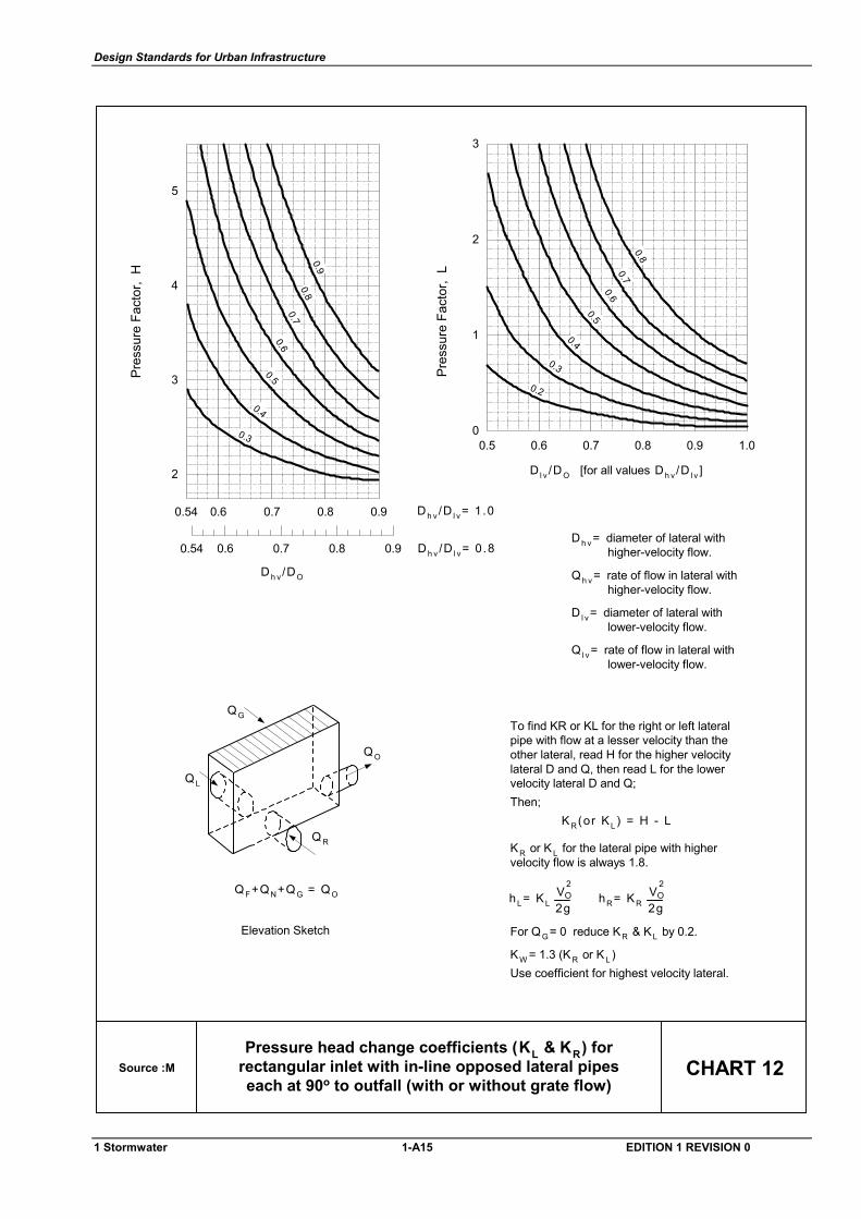
Design Standards for Urban Infrastructure
Source :M CHART 12
0.90.600.5 0.7 0.8
1
2
3
1.0
0.8
0.7
0.6
0.5
0.4
0.3
0.23
2
4
5
0.54 0.80.6 0.7 0.9
0.80.7
0.60.5
0.4
0.3
0.90.54 0.90.80.70.6
Elevation Sketch
QO
Q L
QG
Q R
QF+QN+QG = QO
Pressure head change coefficients (KL & KR) forrectangular inlet with in-line opposed lateral pipeseach at 90o to outfall (with or without grate flow)
Pres
sure
Fac
tor,
H
Pres
sure
Fac
tor,
L
D h v /DO
Dh v /D l v = 1 .0
D l v /DO [for all values Dh v /D l v ]
Dh v /D l v = 0 .8Dh v = diameter of lateral with higher-velocity flow.
Qh v = rate of flow in lateral with higher-velocity flow.
D l v = diameter of lateral with lower-velocity flow.
Q l v = rate of flow in lateral with lower-velocity flow.
To find KR or KL for the right or left lateralpipe with flow at a lesser velocity than theother lateral, read H for the higher velocitylateral D and Q, then read L for the lowervelocity lateral D and Q;Then; KR(or KL) = H - L
KR or KL for the lateral pipe with highervelocity flow is always 1.8.
For QG = 0 reduce KR & KL by 0.2.
KW = 1.3 (K R or KL )Use coefficient for highest velocity lateral.
hL= KL 2gOV2
hR= KR 2gOV2
1 Stormwater 1-A15 EDITION 1 REVISION 0
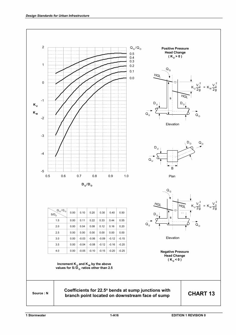
Design Standards for Urban Infrastructure
Source : N CHART 13Coefficients for 22.5o bends at sump junctions withbranch point located on downstream face of sump
QG /QO
0.50.40.30.20.1
0.0
1.00.90.80.70.60.5-5
-4
-3
-2
1
0
1
2
KW
K U
D U /DO
-
Increment KU and K W by the abovevalues for S/D O ratios other than 2.5
0.00
0.00
0.00
0.00
0.00
0.00
0.11
0.04
0.00
-0.03
-0.04
-0.05
0.22
0.08
0.00
-0.06
-0.08
-0.10
0.33
0.12
0.00
-0.09
-0.12
-0.15
0.44
0.16
0.00
-0.12
-0.16
-0.20
0.55
0.20
0.00
-0.15
-0.20
-0.25
1.5
2.0
2.5
3.0
3.5
4.0
0.00 0.10 0.20 0.30 0.40 0.50S/DO
Q G / Q O
Q U
QO
D U
DO
B
Plan
Positive PressureHead Change
( K U > 0 )
s
Elevation
D U D O
QG
Q O
HGL
HGL
s
Elevation
D U ` `
QG
Q O
Negative PressureHead Change
( K U < 0 )
HGLHGL
QU
QU
KU = KW 2g2gVO
2VO2
KU = KW 2g2gVO
2VO2
1 Stormwater 1-A16 EDITION 1 REVISION 0
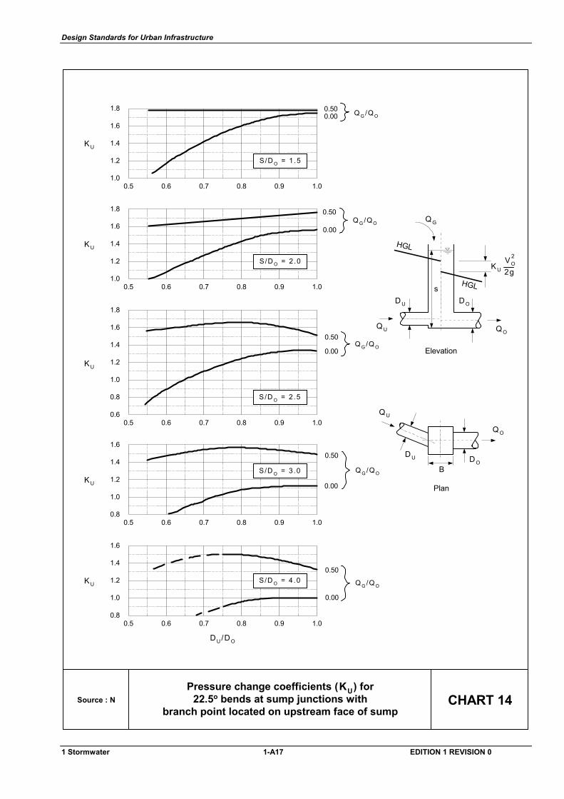
Design Standards for Urban Infrastructure
Source : N CHART 14
1.0
0.6
0.8
1.4
1.2
0.5 0.6 0.7 0.8 0.9 1.0
Q G /Q O
0.50
0.00
KU
1.6
1.8
S/D O = 2 .5
1.4
1.0
1.2
1.8
1.6
0.5 0.6 0.7 0.8 0.9 1.0
S/D O = 2 .0
Q G /Q O0.00
0.50
KU
1.2
0.8
1.0
1.6
1.4
0.5 0.6 0.7 0.8 0.9 1.0
S/D O = 3 .0 Q G /Q O
0.50
0.00KU
1.2
0.8
1.0
1.6
1.4
0.5 0.6 0.7 0.8 0.9 1.0
S/D O = 4 .0 Q G /Q O
0.50
0.00
KU
DU/DO
Pressure change coefficients (KU) for22.5o bends at sump junctions with
branch point located on upstream face of sump
1.4
1.0
1.2
1.8
1.6
0.5 0.6 0.7 0.8 0.9 1.0
S/D O = 1 .5
Q G /Q O0.000.50
KU
s
Elevation
D U DO
QG
QO
HGL
HGL
KU 2gVO
2
QU
Q O
Q U
D OD U
B
Plan
1 Stormwater 1-A17 EDITION 1 REVISION 0
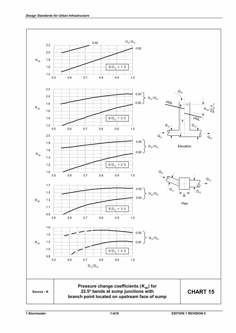
Design Standards for Urban Infrastructure
Source : N CHART 15Pressure change coefficients (KW) for
22.5o bends at sump junctions withbranch point located on upstream face of sump
KW 2gVO
2
s
Elevation
D U DO
QG
QO
HGL
HGL
QU
1.8
1.4
1.6
2.2
2.0
0.5 0.6 0.7 0.8 0.9 1.0
S/D O = 1 .5
Q G /Q O
0.00
0.50
KW
1.6
1.2
1.4
2.0
1.8
0.5 0.6 0.7 0.8 0.9 1.0
Q G /Q O
0.50
0.00KW
2.2
S/D O = 2 .0
1.4
1.0
1.2
1.8
1.6
0.5 0.6 0.7 0.8 0.9 1.0
Q G /Q O
0.50
0.00KW
2.0
S/D O = 2 .5
1.3
0.9
1.1
1.7
1.5
0.5 0.6 0.7 0.8 0.9 1.0
S/D O = 3 .0
Q G /Q O
0.50
0.00KW
1.2
0.8
1.0
1.6
1.4
0.5 0.6 0.7 0.8 0.9 1.0
S/D O = 4 .0
Q G /Q O
0.50
0.00KW
DU/DO
Q O
Q U
D OD U
B
Plan
1 Stormwater 1-A18 EDITION 1 REVISION 0
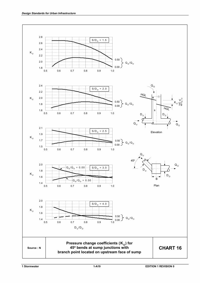
Design Standards for Urban Infrastructure
Source : N CHART 16Pressure change coefficients (KU) for
45o bends at sump junctions withbranch point located on upstream face of sump
Q O
Q U
D O
D U
B
Plan
45o
2.2
1.8
2.0
2.6
2.4
0.5 0.6 0.7 0.8 0.9 1.0
Q G /Q O
0.50
0.00
KU
2.8S/D O = 1 .5
2.0
1.6
1.8
2.4
2.2
0.5 0.6 0.7 0.8 0.9 1.0
S/D O = 2 .0
KU
Q G /Q O0.500.00
1.9
1.5
1.7
2.1
0.5 0.6 0.7 0.8 0.9 1.0
Q G /Q O0.500.00
KU
S/D O = 2 .5
DU/DO
1.8
1.4
1.6
2.0
0.5 0.6 0.7 0.8 0.9 1.0Q G /Q O
0.500.00
KU
S/D O = 4 .0
1.8
1.4
1.6
2.0
0.5 0.6 0.7 0.8 0.9 1.0
KU
Q G /Q O = 0 .00
Q G /Q O = 0 .00
S/D O = 3 .0
s
Elevation
D U DO
QG
QO
HGL
HGL
KU 2gVO
2
QU
1 Stormwater 1-A19 EDITION 1 REVISION 0
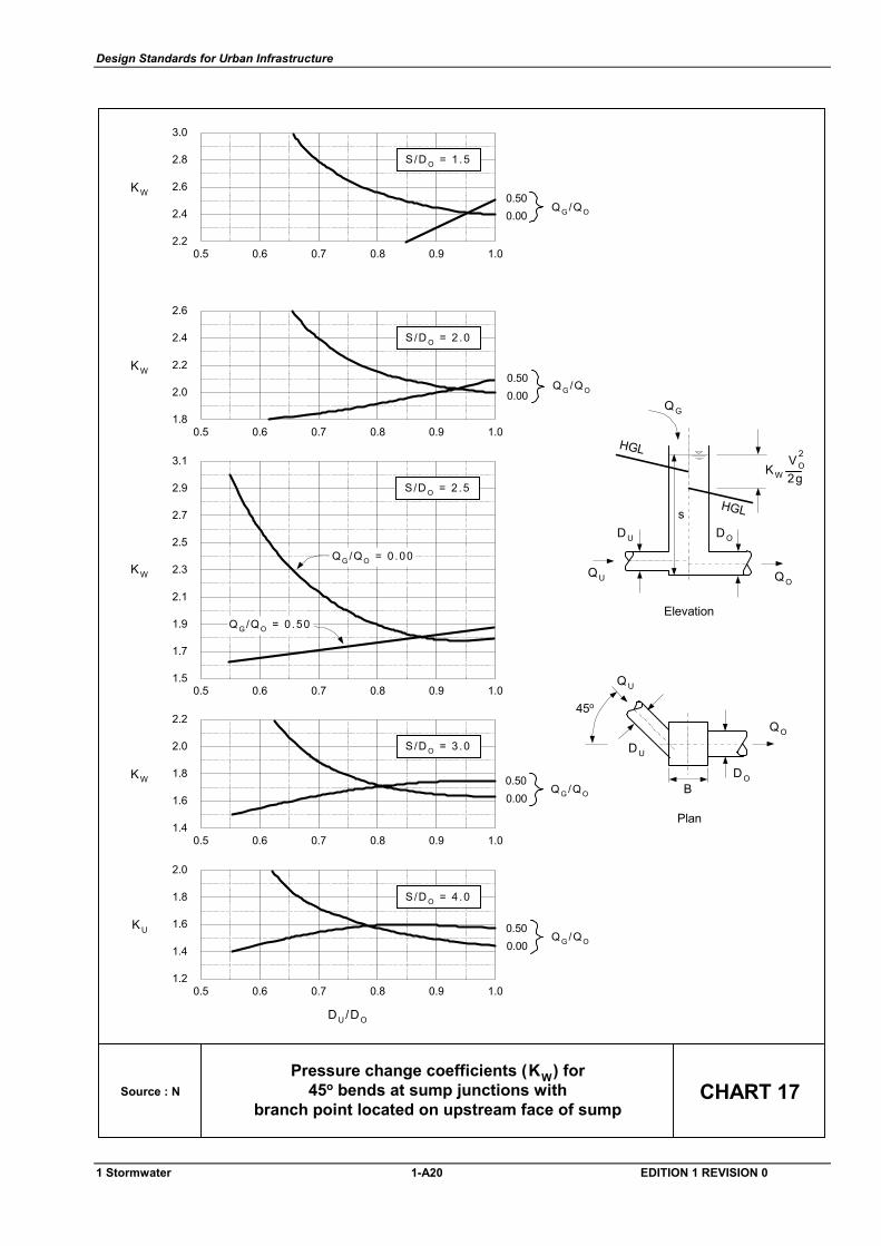
Design Standards for Urban Infrastructure
Source : N CHART 17Pressure change coefficients (KW) for
45o bends at sump junctions withbranch point located on upstream face of sump
Q O
Q U
D O
D U
B
Plan
45o
2.6
2.2
2.4
3.0
2.8
0.5 0.6 0.7 0.8 0.9 1.0
S/D O = 1 .5
KW
Q G /Q O0.500.00
1.8
1.4
1.6
2.2
2.0
0.5 0.6 0.7 0.8 0.9 1.0
S/D O = 3 .0
KWQ G /Q O
0.500.00
1.6
1.2
1.4
2.0
1.8
0.5 0.6 0.7 0.8 0.9 1.0
S/D O = 4 .0
KUQ G /Q O
0.500.00
DU/DO
s
Elevation
D U DO
QG
QO
HGL
HGL
KW 2gVO
2
QU
2.2
1.8
2.0
2.6
2.4
0.5 0.6 0.7 0.8 0.9 1.0
S/D O = 2 .0
KW
Q G /Q O0.500.00
2.3
1.9
2.1
2.7
2.5
KW
2.9
3.1
0.5 0.6 0.7 0.8 0.9 1.01.5
1.7
Q G /Q O = 0 .50
Q G /Q O = 0 .00
S/D O = 2 .5
1 Stormwater 1-A20 EDITION 1 REVISION 0
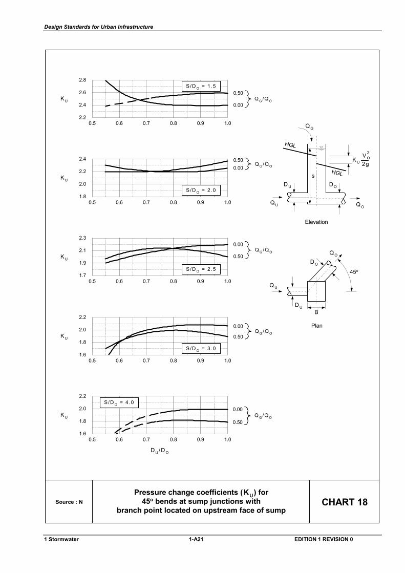
Design Standards for Urban Infrastructure
Source : N CHART 18Pressure change coefficients (KU) for
45o bends at sump junctions withbranch point located on upstream face of sump
sD U DO
QG
QO
HGL
HGL
KU 2gVO
2
Elevation
QU
QO
QU
D O
DUB
Plan
45o
DU/DO
2.0
1.6
1.8
2.2
0.5 0.6 0.7 0.8 0.9 1.0
Q G /Q O0.50
0.00KU
S/D O = 4 .0
2.0
1.6
1.8
2.2
0.5 0.6 0.7 0.8 0.9 1.0
Q G /Q O0.50
0.00
KU
S/D O = 3 .0
2.1
1.7
1.9
2.3
0.5 0.6 0.7 0.8 0.9 1.0
Q G /Q O0.50
0.00
KU
S/D O = 2 .5
2.2
1.8
2.0
2.4
0.5 0.6 0.7 0.8 0.9 1.0
Q G /Q O0.500.00
KU
S/D O = 2 .0
2.6
2.2
2.4
2.8
0.5 0.6 0.7 0.8 0.9 1.0
Q G /Q O
0.50
0.00KU
S/D O = 1 .5
1 Stormwater 1-A21 EDITION 1 REVISION 0
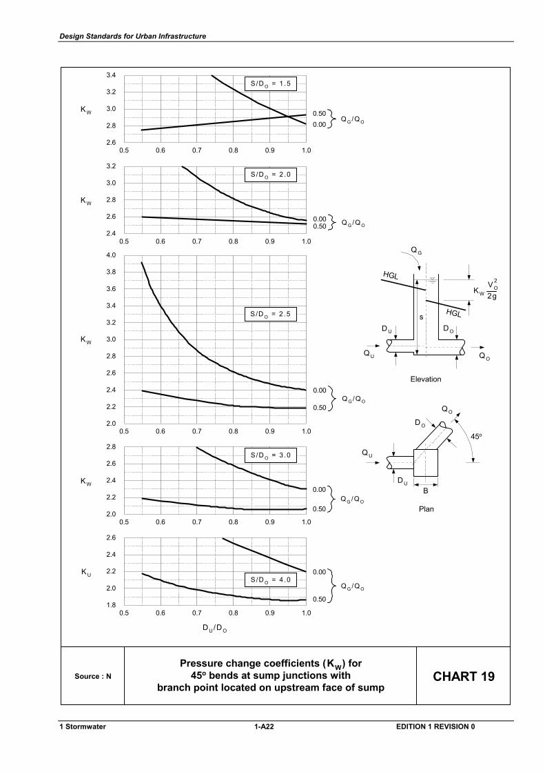
Design Standards for Urban Infrastructure
Source : N CHART 19Pressure change coefficients (KW) for
45o bends at sump junctions withbranch point located on upstream face of sump
2.2
1.8
2.0
2.6
2.4
0.5 0.6 0.7 0.8 0.9 1.0
S/D O = 4 .0KU
Q G /Q O
0.50
0.00
DU/DO
2.4
2.0
2.2
2.8
2.6
0.5 0.6 0.7 0.8 0.9 1.0
S/D O = 3 .0
KW
Q G /Q O
0.50
0.00
2.8
2.4
2.6
3.2
3.0KW
3.4
3.6
0.5 0.6 0.7 0.8 0.9 1.02.0
2.2
3.8
4.0
0.00
0.50
S/D O = 2 .5
2.8
2.4
2.6
3.2
3.0
0.5 0.6 0.7 0.8 0.9 1.0
S/D O = 2 .0
KW
Q G /Q O0.000.50
3.0
2.6
2.8
3.4
3.2
0.5 0.6 0.7 0.8 0.9 1.0
S/D O = 1 .5
KWQ G /Q O
0.500.00
sD U DO
QG
QO
HGL
HGL
Elevation
QU
QO
QU
D O
DUB
Plan
45o
Q G /Q O
KW 2gVO
2
1 Stormwater 1-A22 EDITION 1 REVISION 0
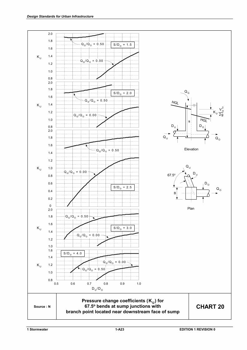
Design Standards for Urban Infrastructure
Source : N CHART 20Pressure change coefficients (KU) for
67.5o bends at sump junctions withbranch point located near downstream face of sump
1.2
0.8
1.0
1.6
1.4
0.5 0.6 0.7 0.8 0.9 1.0
S/D O = 4 .0
KU
DU/DO
Q G /Q O = 0 .50
Q G /Q O = 0 .00
1.2
1.0
1.6
1.4KU
1.8
2.0
S/D O = 2 .0
Q G /Q O = 0 .50
Q G /Q O = 0 .00
1.2
0.8
1.0
1.6
1.4KU
1.8
2.0
S/D O = 1 .5Q G /Q O = 0 .50
Q G /Q O = 0 .00
0.8
0.4
0
0.2
0.8
0.6
KU 1.0
1.2
2.0
1.4
1.8
1.6
2.0
S/D O = 2 .5
Q G /Q O = 0 .50
Q G /Q O = 0 .00
1.4
1.0
1.2
1.8
1.6KU S/D O = 3 .0
Q G /Q O = 0 .50
Q G /Q O = 0 .00
s
Elevation
HGL
HGL
QG
D U D O
Q OQU
Plan
Q O
QU
D U
B
67.5o
D O
KU 2gVO
2
1 Stormwater 1-A23 EDITION 1 REVISION 0
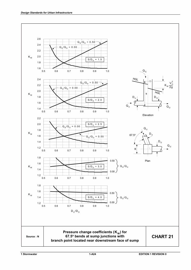
Design Standards for Urban Infrastructure
Source : N CHART 21Pressure change coefficients (KW) for
67.5o bends at sump junctions withbranch point located near downstream face of sump
DU/DO
1.6
1.2
1.4
1.8
0.5 0.6 0.7 0.8 0.9 1.0
Q G /Q O
0.50
0.00
KWS/D O = 4 .0
1.6
1.2
1.4
1.8
0.5 0.6 0.7 0.8 0.9 1.0
0.50
0.00
KW S/D O = 3 .0 Q G /Q O
1.6
1.2
1.4
2.0
1.8
0.5 0.6 0.7 0.8 0.9 1.0
KW
2.2
S/D O = 2 .5
Q G /Q O = 0 .50
Q G /Q O = 0 .00
1.8
1.4
1.6
2.2
2.0
0.5 0.6 0.7 0.8 0.9 1.0
KW
2.4
S/D O = 2 .0
Q G /Q O = 0 .50
Q G /Q O = 0 .00
2.0
1.6
1.8
2.4
2.2
0.5 0.6 0.7 0.8 0.9 1.0
KW
2.6
S/D O = 1 .5
Q G /Q O = 0 .50
Q G /Q O = 0 .00
s
Elevation
HGL
HGL
QG
D U D O
Q OQU
Plan
Q O
QU
D U
B
67.5o
D O
KW 2gVO
2
1 Stormwater 1-A24 EDITION 1 REVISION 0
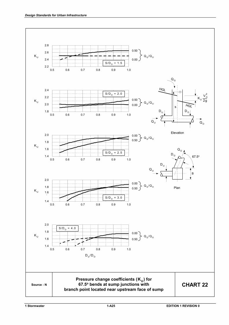
Design Standards for Urban Infrastructure
Source : N CHART 22Pressure change coefficients (KU) for
67.5o bends at sump junctions withbranch point located near upstream face of sump
2.6
2.2
2.4
2.8
0.5 0.6 0.7 0.8 0.9 1.0
Q G /Q O
0.50
0.00KU
S/D O = 1 .5
2.2
1.8
2.0
2.4
0.5 0.6 0.7 0.8 0.9 1.0
Q G /Q O
0.50
0.00KU
S/D O = 2 .0
1.8
1.4
1.6
2.0
0.5 0.6 0.7 0.8 0.9 1.0
Q G /Q O0.500.00
KU
S/D O = 2 .5
1.8
1.4
1.6`
2.0
0.5 0.6 0.7 0.8 0.9 1.0
Q G /Q O0.50
0.00
KU
S/D O = 3 .0
DU/DO
1.8
1.4
1.6
2.0
0.5 0.6 0.7 0.8 0.9 1.0
Q G /Q O0.50
0.00KU
S/D O = 4 .0
s
Elevation
HGL
HGL
QG
D U D O
Q OQU
67.5o
KU 2gVO
2
Plan
Q U
QO
DO
B
D U
1 Stormwater 1-A25 EDITION 1 REVISION 0
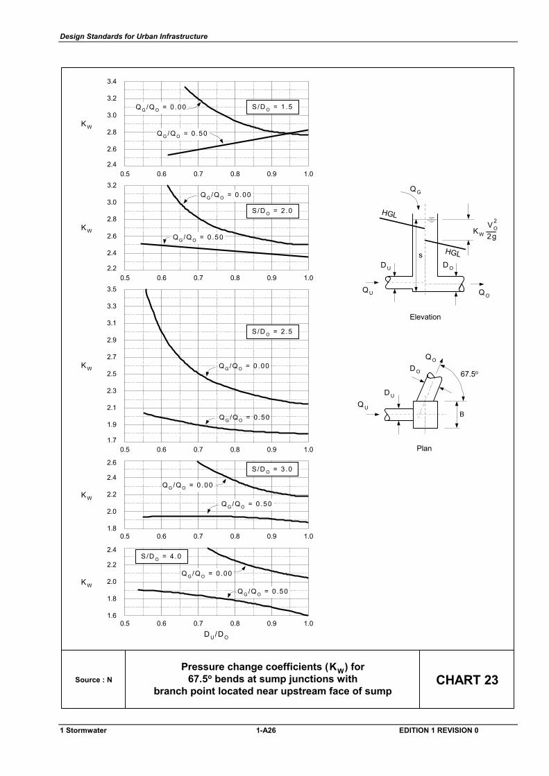
Design Standards for Urban Infrastructure
CHART 23Source : NPressure change coefficients (KW) for
67.5o bends at sump junctions withbranch point located near upstream face of sump
s
Elevation
HGL
HGL
QG
D U D O
Q OQU
67.5o
Plan
Q U
QO
DO
B
D U
KW 2gVO
2
2.8
2.4
2.6
3.2
3.0KW
S/D O = 1 .5Q G /Q O = 0 .00
Q G /Q O = 0 .50
0.5 0.6 0.7 0.8 0.9 1.0
3.4
2.6
2.2
2.4
3.0
2.8KW
S/D O = 2 .0
Q G /Q O = 0 .50
Q G /Q O = 0 .00
0.5 0.6 0.7 0.8 0.9 1.0
3.2
2.2
1.8
2.0
2.6
2.4
0.5 0.6 0.7 0.8 0.9 1.0
S/D O = 3 .0
KWQ G /Q O = 0 .50
Q G /Q O = 0 .00
2.0
1.6
1.8
2.4
2.2
0.5 0.6 0.7 0.8 0.9 1.0
S/D O = 4 .0
KW
D U/DO
Q G /Q O = 0 .50
Q G /Q O = 0 .00
2.1
1.7
1.9
2.5
2.3
KW
2.7
2.9
3.1
3.5
3.3
Q G /Q O = 0 .50
Q G /Q O = 0 .00
0.5 0.6 0.7 0.8 0.9 1.0
S/D O = 2 .5
1 Stormwater 1-A26 EDITION 1 REVISION 0