Embed Size (px)
Citation preview
Design, Simulation, and Testing of a Flexible Actuated Spine forQuadruped Robots
Andrew P. Sabelhaus1*, Student Member, IEEE, Lara Janse van Vuuren1, Ankita Joshi1,Edward Zhu1, Hunter J. Garnier1, Kimberly A. Sover1, Jesus Navarro1,
Adrian K. Agogino2, Alice M. Agogino1, Senior Member, IEEE
Abstract— Walking quadruped robots face challenges in po-sitioning their feet and lifting their legs during gait cycles overuneven terrain. The robot Laika is under development as aquadruped with a flexible, actuated spine designed to assistwith foot movement and balance during these gaits. This paperpresents the first set of hardware designs for the spine of Laika,a physical prototype of those designs, and tests in both hardwareand simulations that show the prototype’s capabilities. Laika’sspine is a tensegrity structure, used for its advantages withweight and force distribution, and represents the first workingprototype of a tensegrity spine for a quadruped robot. Thespine bends by adjusting the lengths of the cables that separateits vertebrae, and twists using an actuated rotating vertebra atits center. The current prototype of Laika has stiff legs attachedto the spine, and is used as a test setup for evaluation of thespine itself. This work shows the advantages of Laika’s spineby demonstrating the spine lifting each of the robot’s four feet,both as a form of balancing and as a precursor for a walkinggait. These foot motions, using specific combinations of bendingand rotation movements of the spine, are measured in bothsimulation and hardware experiments. Hardware data are usedto calibrate the simulations, such that the simulations can beused for control of balancing or gait cycles in the future. Futurework will attach actuated legs to Laika’s spine, and examinebalancing and gait cycles when combined with leg movements.
I. INTRODUCTIONWalking over uneven terrain is a common goal of many
robotic systems, especially for quadruped (four-legged)robots [1], [2], [3], [4], [5], [6], [7], [8]. Such terrain couldbe as diverse as the stairs inside buildings [8], [9], [10]or rocky planets. However, balancing and locomotion overlarge obstacles can be challenging for robots built with rigidstructures that cannot conform to the environment, limitingthem to obstacles that are small in comparison to their totalsize [11], [2].
This research presents a flexible, actuated spine forquadruped robots that can assist in a robot’s locomotion overuneven terrain in space applications. The spine is used hereas part of an early prototype of the robot Laika, named afterthe first dog in space, as adapted from earlier concepts [12].
*Authors with the NASA Ames Research Center Intelligent RoboticsGroup, Moffett Field, CA 94035, USA
1A.P. Sabelhaus, L. Janse van Vuuren, A. Joshi, E. Zhu, H.J. Garnier, K.A.Sover, J. Navarro, and A.M. Agogino are with the Department of MechanicalEngineering, University of California Berkeley, USA apsabelhaus,larajvv, ankitaj, edward.zhu, hgarnier,kasover, foamjay, agogino @berkeley.edu
2A.K. Agogino is with the Intelligent Systems Divison,NASA Ames Research Center, Moffet Field CA [email protected]
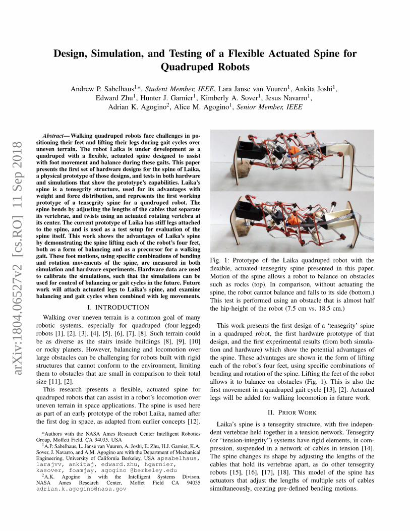
Fig. 1: Prototype of the Laika quadruped robot with theflexible, actuated tensegrity spine presented in this paper.Motion of the spine allows a robot to balance on obstaclessuch as rocks (top). In comparison, without actuating thespine, the robot cannot balance and falls to its side (bottom.)This test is performed using an obstacle that is almost halfthe hip-height of the robot (7.5 cm vs. 18.5 cm.)
This work presents the first design of a ‘tensegrity’ spinein a quadruped robot, the first hardware prototype of thatdesign, and the first experimental results (from both simula-tion and hardware) which show the potential advantages ofthe spine. These advantages are shown in the form of liftingeach of the robot’s four feet, using specific combinations ofbending and rotation of the spine. Lifting the feet of the robotallows it to balance on obstacles (Fig. 1). This is also thefirst movement in a quadruped gait cycle [13], [2]. Actuatedlegs will be added for walking locomotion in future work.
II. PRIOR WORK
Laika’s spine is a tensegrity structure, with five indepen-dent vertebrae held together in a tension network. Tensegrity(or “tension-integrity”) systems have rigid elements, in com-pression, suspended in a network of cables in tension [14].The spine changes its shape by adjusting the lengths of thecables that hold its vertebrae apart, as do other tensegrityrobots [15], [16], [17], [18]. This model of the spine hasactuators that adjust the lengths of multiple sets of cablessimultaneously, creating pre-defined bending motions.
arX
iv:1
804.
0652
7v2
[cs
.RO
] 1
1 Se
p 20
18
A large body of other work on quadruped robots hasincorporated a spine in different ways. [19], [20], [21], [22],[23], [24], [9], [25], including passive and actuated designsfor different purposes. Laika and its spine differ from priorquadrupeds with spines in multiple important ways.
First, Laika’s spine is both actively actuated and passivelycompliant. Other passive spines that assist with locomotioncannot actively move to balance the robot [19], [20], [26].In contrast, robots with actuated spines often do not includecompliance or flexible mechanisms [27], [28], enforcingsignificant design constraints for walking over obstacles.
Second, Laika’s spine can perform complex and multi-degree-of-freedom motions simultaneously, including themain three studied in spine robots: axial rotation, and bend-ing in both the sagittal and coronal planes. Other robots withboth flexible and fixed-twisting spines are often designed forto sagittal-only [21], [24] or coronal-only [29] bending.
Third, Laika’s spine is designed for balancing and ad-justing the robot’s foot placement. Other spines are morecommonly used as a part of a dynamic running or gallopinggait [21], [22], [24], or as an input to change the directionof running [29].
Finally, this is the first spine built as a tensegrity sys-tem. This approach includes adjustable compliance, passiveforce distribution, redundancy and robustness to failure, andlightweight construction [30], [12], [15].
III. ROBOT STRUCTURE
The current design of Laika consists of a spine supportedby rigid hips, shoulders, and legs. As its spine moves, thecenter of mass shifts in three dimensions, enabling lifting ofeach foot accordingly. The design of the robot’s vertebrae,and its tendon placement, evolved from both biologicalconcepts as well as iteration on designs that could createall three basic motions [12]. Actuated legs will be added infuture work to test the spine with locomotion.
A. Spine Topology
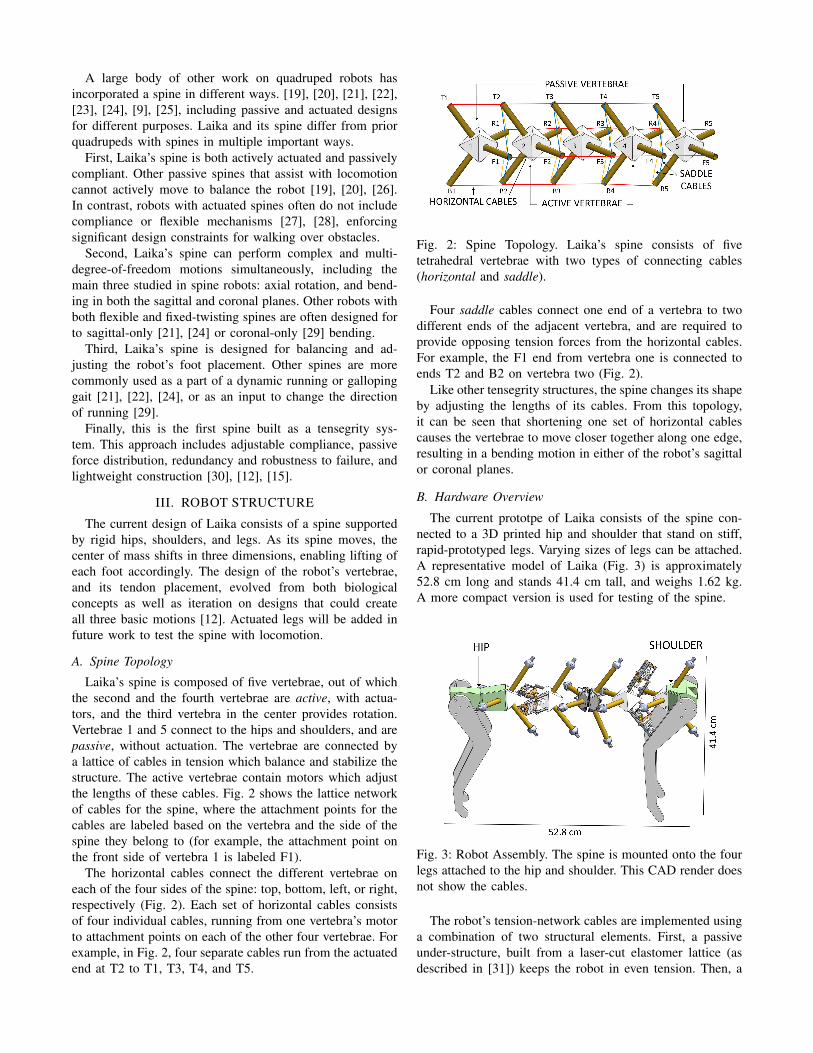
Laika’s spine is composed of five vertebrae, out of whichthe second and the fourth vertebrae are active, with actua-tors, and the third vertebra in the center provides rotation.Vertebrae 1 and 5 connect to the hips and shoulders, and arepassive, without actuation. The vertebrae are connected bya lattice of cables in tension which balance and stabilize thestructure. The active vertebrae contain motors which adjustthe lengths of these cables. Fig. 2 shows the lattice networkof cables for the spine, where the attachment points for thecables are labeled based on the vertebra and the side of thespine they belong to (for example, the attachment point onthe front side of vertebra 1 is labeled F1).
The horizontal cables connect the different vertebrae oneach of the four sides of the spine: top, bottom, left, or right,respectively (Fig. 2). Each set of horizontal cables consistsof four individual cables, running from one vertebra’s motorto attachment points on each of the other four vertebrae. Forexample, in Fig. 2, four separate cables run from the actuatedend at T2 to T1, T3, T4, and T5.
Fig. 2: Spine Topology. Laika’s spine consists of fivetetrahedral vertebrae with two types of connecting cables(horizontal and saddle).
Four saddle cables connect one end of a vertebra to twodifferent ends of the adjacent vertebra, and are required toprovide opposing tension forces from the horizontal cables.For example, the F1 end from vertebra one is connected toends T2 and B2 on vertebra two (Fig. 2).
Like other tensegrity structures, the spine changes its shapeby adjusting the lengths of its cables. From this topology,it can be seen that shortening one set of horizontal cablescauses the vertebrae to move closer together along one edge,resulting in a bending motion in either of the robot’s sagittalor coronal planes.
B. Hardware Overview
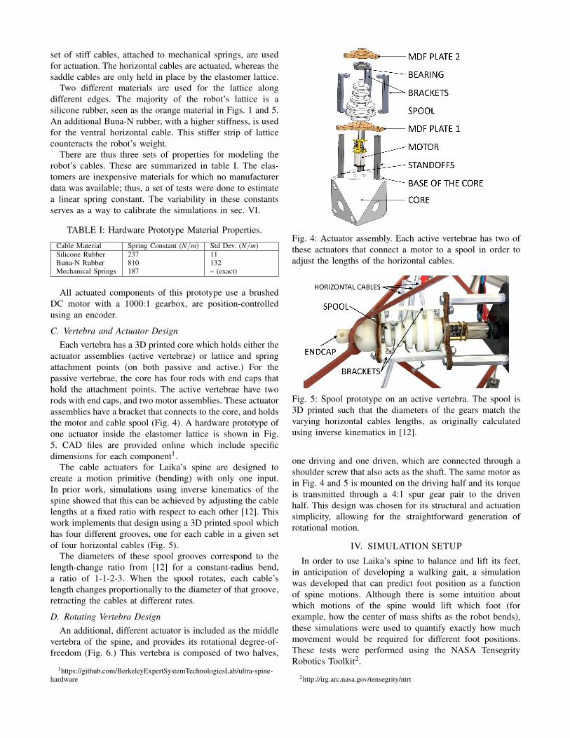
The current prototpe of Laika consists of the spine con-nected to a 3D printed hip and shoulder that stand on stiff,rapid-prototyped legs. Varying sizes of legs can be attached.A representative model of Laika (Fig. 3) is approximately52.8 cm long and stands 41.4 cm tall, and weighs 1.62 kg.A more compact version is used for testing of the spine.
Fig. 3: Robot Assembly. The spine is mounted onto the fourlegs attached to the hip and shoulder. This CAD render doesnot show the cables.
The robot’s tension-network cables are implemented usinga combination of two structural elements. First, a passiveunder-structure, built from a laser-cut elastomer lattice (asdescribed in [31]) keeps the robot in even tension. Then, a
set of stiff cables, attached to mechanical springs, are usedfor actuation. The horizontal cables are actuated, whereas thesaddle cables are only held in place by the elastomer lattice.
Two different materials are used for the lattice alongdifferent edges. The majority of the robot’s lattice is asilicone rubber, seen as the orange material in Figs. 1 and 5.An additional Buna-N rubber, with a higher stiffness, is usedfor the ventral horizontal cable. This stiffer strip of latticecounteracts the robot’s weight.
There are thus three sets of properties for modeling therobot’s cables. These are summarized in table I. The elas-tomers are inexpensive materials for which no manufacturerdata was available; thus, a set of tests were done to estimatea linear spring constant. The variability in these constantsserves as a way to calibrate the simulations in sec. VI.
TABLE I: Hardware Prototype Material Properties.
Cable Material Spring Constant (N/m) Std Dev. (N/m)Silicone Rubber 237 11Buna-N Rubber 810 132Mechanical Springs 187 – (exact)
All actuated components of this prototype use a brushedDC motor with a 1000:1 gearbox, are position-controlledusing an encoder.
C. Vertebra and Actuator DesignEach vertebra has a 3D printed core which holds either the
actuator assemblies (active vertebrae) or lattice and springattachment points (on both passive and active.) For thepassive vertebrae, the core has four rods with end caps thathold the attachment points. The active vertebrae have tworods with end caps, and two motor assemblies. These actuatorassemblies have a bracket that connects to the core, and holdsthe motor and cable spool (Fig. 4). A hardware prototype ofone actuator inside the elastomer lattice is shown in Fig.5. CAD files are provided online which include specificdimensions for each component1.
The cable actuators for Laika’s spine are designed tocreate a motion primitive (bending) with only one input.In prior work, simulations using inverse kinematics of thespine showed that this can be achieved by adjusting the cablelengths at a fixed ratio with respect to each other [12]. Thiswork implements that design using a 3D printed spool whichhas four different grooves, one for each cable in a given setof four horizontal cables (Fig. 5).
The diameters of these spool grooves correspond to thelength-change ratio from [12] for a constant-radius bend,a ratio of 1-1-2-3. When the spool rotates, each cable’slength changes proportionally to the diameter of that groove,retracting the cables at different rates.
D. Rotating Vertebra DesignAn additional, different actuator is included as the middle
vertebra of the spine, and provides its rotational degree-of-freedom (Fig. 6.) This vertebra is composed of two halves,
1https://github.com/BerkeleyExpertSystemTechnologiesLab/ultra-spine-hardware
Fig. 4: Actuator assembly. Each active vertebrae has two ofthese actuators that connect a motor to a spool in order toadjust the lengths of the horizontal cables.
Fig. 5: Spool prototype on an active vertebra. The spool is3D printed such that the diameters of the gears match thevarying horizontal cables lengths, as originally calculatedusing inverse kinematics in [12].
one driving and one driven, which are connected through ashoulder screw that also acts as the shaft. The same motor asin Fig. 4 and 5 is mounted on the driving half and its torqueis transmitted through a 4:1 spur gear pair to the drivenhalf. This design was chosen for its structural and actuationsimplicity, allowing for the straightforward generation ofrotational motion.
IV. SIMULATION SETUP
In order to use Laika’s spine to balance and lift its feet,in anticipation of developing a walking gait, a simulationwas developed that can predict foot position as a functionof spine motions. Although there is some intuition aboutwhich motions of the spine would lift which foot (forexample, how the center of mass shifts as the robot bends),these simulations were used to quantify exactly how muchmovement would be required for different foot positions.These tests were performed using the NASA TensegrityRobotics Toolkit2.
2http://irg.arc.nasa.gov/tensegrity/ntrt
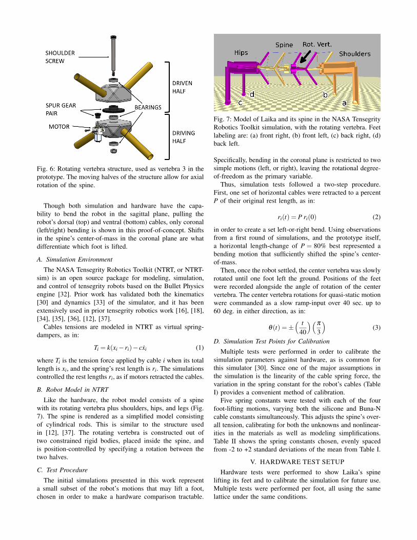
Fig. 6: Rotating vertebra structure, used as vertebra 3 in theprototype. The moving halves of the structure allow for axialrotation of the spine.
Though both simulation and hardware have the capa-bility to bend the robot in the sagittal plane, pulling therobot’s dorsal (top) and ventral (bottom) cables, only coronal(left/right) bending is shown in this proof-of-concept. Shiftsin the spine’s center-of-mass in the coronal plane are whatdifferentiate which foot is lifted.
A. Simulation Environment
The NASA Tensegrity Robotics Toolkit (NTRT, or NTRT-sim) is an open source package for modeling, simulation,and control of tensegrity robots based on the Bullet Physicsengine [32]. Prior work has validated both the kinematics[30] and dynamics [33] of the simulator, and it has beenextensively used in prior tensegrity robotics work [16], [18],[34], [35], [36], [12], [37].
Cables tensions are modeled in NTRT as virtual spring-dampers, as in:
Ti = k(xi − ri)− cxi (1)
where Ti is the tension force applied by cable i when its totallength is xi, and the spring’s rest length is ri. The simulationscontrolled the rest lengths ri, as if motors retracted the cables.
B. Robot Model in NTRT
Like the hardware, the robot model consists of a spinewith its rotating vertebra plus shoulders, hips, and legs (Fig.7). The spine is rendered as a simplified model consistingof cylindrical rods. This is similar to the structure usedin [12], [37]. The rotating vertebra is constructed out oftwo constrained rigid bodies, placed inside the spine, andis position-controlled by specifying a rotation between thetwo halves.
C. Test Procedure
The initial simulations presented in this work representa small subset of the robot’s motions that may lift a foot,chosen in order to make a hardware comparison tractable.
Fig. 7: Model of Laika and its spine in the NASA TensegrityRobotics Toolkit simulation, with the rotating vertebra. Feetlabeling are: (a) front right, (b) front left, (c) back right, (d)back left.
Specifically, bending in the coronal plane is restricted to twosimple motions (left, or right), leaving the rotational degree-of-freedom as the primary variable.
Thus, simulation tests followed a two-step procedure.First, one set of horizontal cables were retracted to a percentP of their original rest length, as in:
ri(t) = P ri(0) (2)
in order to create a set left-or-right bend. Using observationsfrom a first round of simulations, and the prototype itself,a horizontal length-change of P = 80% best represented abending motion that sufficiently shifted the spine’s center-of-mass.
Then, once the robot settled, the center vertebra was slowlyrotated until one foot left the ground. Positions of the feetwere recorded alongside the angle of rotation of the centervertebra. The center vertebra rotations for quasi-static motionwere commanded as a slow ramp-input over 40 sec. up to60 deg. in either direction, as in:
θ(t) =±( t
40
)(π
3
)(3)
D. Simulation Test Points for Calibration
Multiple tests were performed in order to calibrate thesimulation parameters against hardware, as is common forthis simulator [30]. Since one of the major assumptions inthe simulation is the linearity of the cable spring force, thevariation in the spring constant for the robot’s cables (TableI) provides a convenient method of calibration.
Five spring constants were tested with each of the fourfoot-lifting motions, varying both the silicone and Buna-Ncable constants simultaneously. This adjusts the spine’s over-all tension, calibrating for both the unknowns and nonlinear-ities in the materials as well as modeling simplifications.Table II shows the spring constants chosen, evenly spacedfrom -2 to +2 standard deviations of the mean from Table I.
V. HARDWARE TEST SETUP
Hardware tests were performed to show Laika’s spinelifting its feet and to calibrate the simulation for future use.Multiple tests were performed per foot, all using the samelattice under the same conditions.

TABLE II: Five spring constant test points (in N/m) for thesimulation, adjusting the overall tension of the robot.
Material Low(−2σ )
Med-Low
Mean(µ)
Med-High
High(+2σ )
Silicone 216 227 237 248 258Buna-N 547 678 810 941 1073
A. Hardware Testing Platform
The prototype of Laika was set up in placed of a camera,with off-board power and control (Fig. 8). The robot’s controlsystem consisted of microcontroller connected to a powersupply, with two connected motors: one for a horizontalcable set, and one for the center vertebra. Power cableswere wound through the spine to connect the motors to thecontroller. During testing, the motors’ encoders were usedto track rotations, which were converted to percent-length-change in the controller.
B. Hardware Test Procedure
For each test, the spine was actuated along the sametrajectories as in sec. IV-C for the simulation. Switchingbetween tests involved rotating the robot, re-routing themotors’ cables, and if needed, attaching and detaching therequired horizontal cables. The robot was rotated by 180degrees when switching between the tests for its anterior andposterior ends. This required re-routing the motors’ cables,causing a slight change in center-of-mass.
Prior to each test, the single set of actuated horizontalcables were tensioned until just past slackness, as an ap-proximation to the simulation’s initial conditions. Markerswere placed on the bed of the test setup, and the robot wasre-positioned to the same state between tests.
For each test, the video camera recorded the feet as thecontroller tracked the rotations. A small LED, placed withinthe viewing frame of the camera, was activated at the startof the test, and a time series of data was recorded from themicrocontroller. After each test, the video was analyzed forthe time at which the LED activated, and at which the desiredfoot just began to lift. This time difference was then indexedinto the controller data to find the rotation at that time.
Fig. 8: One test of Laika’s spine. An offboard control circuitpowered the motors and tracked rotations, and an LED wasactivated at the start of the test such that the video camera(out-of-frame) could correlate timestamps.
VI. RESULTS
By choosing four combinations of rotation direction andcoronal-plane bending, Laika’s spine was able to lift eachof its four feet. Each of the four motions are summarized inTable III, and shown in Fig. 10 on the following page. Thesemotions can be interpreted as a rotation lifting one diagonalset of legs, and bending shifting the robot’s mass to raiseone foot or the other.
TABLE III: Motion combinations of spine for foot lifting.
Bend Dir. / Cabled Pulled Vert. Rotation Dir. Foot Lifted?Left Bend / Horiz. Right (+), CCW A, Front RightRight Bend / Horiz. Left (+), CCW C, Back LeftLeft Bend / Horiz. Right (-), CW B, Front LeftRight Bend / Horiz. Left (-), CW D, Back Right
A. Foot Position and Required Rotation
The results of five hardware tests per foot are plottedagainst the simulation results in Fig. 9. The center-vertebrarotations at foot lift-off, observed in hardware, are plotted asblack vertical lines representing the minimum and maximumdatapoints. Colored curves are simulation data at the differentlattice tension levels from Table II.
Fig. 9: Simulations and hardware results of foot-lifting testsfor Laika’s spine. Black dashed lines represent the range oflift-off points in hardware. Colored curves represent verticalposition of each foot (A, B, C, D) at varying levels oflattice tension in simulation. The highest-tension simulationresult (red) matches hardware most closely, and represents acalibration of the simulation for future work.
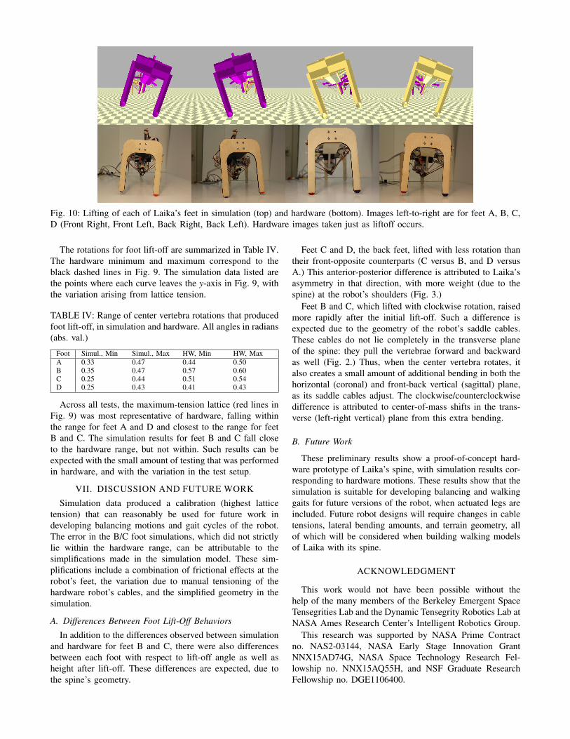
Fig. 10: Lifting of each of Laika’s feet in simulation (top) and hardware (bottom). Images left-to-right are for feet A, B, C,D (Front Right, Front Left, Back Right, Back Left). Hardware images taken just as liftoff occurs.
The rotations for foot lift-off are summarized in Table IV.The hardware minimum and maximum correspond to theblack dashed lines in Fig. 9. The simulation data listed arethe points where each curve leaves the y-axis in Fig. 9, withthe variation arising from lattice tension.
TABLE IV: Range of center vertebra rotations that producedfoot lift-off, in simulation and hardware. All angles in radians(abs. val.)
Foot Simul., Min Simul., Max HW, Min HW, MaxA 0.33 0.47 0.44 0.50B 0.35 0.47 0.57 0.60C 0.25 0.44 0.51 0.54D 0.25 0.43 0.41 0.43
Across all tests, the maximum-tension lattice (red lines inFig. 9) was most representative of hardware, falling withinthe range for feet A and D and closest to the range for feetB and C. The simulation results for feet B and C fall closeto the hardware range, but not within. Such results can beexpected with the small amount of testing that was performedin hardware, and with the variation in the test setup.
VII. DISCUSSION AND FUTURE WORK
Simulation data produced a calibration (highest latticetension) that can reasonably be used for future work indeveloping balancing motions and gait cycles of the robot.The error in the B/C foot simulations, which did not strictlylie within the hardware range, can be attributable to thesimplifications made in the simulation model. These sim-plifications include a combination of frictional effects at therobot’s feet, the variation due to manual tensioning of thehardware robot’s cables, and the simplified geometry in thesimulation.
A. Differences Between Foot Lift-Off Behaviors
In addition to the differences observed between simulationand hardware for feet B and C, there were also differencesbetween each foot with respect to lift-off angle as well asheight after lift-off. These differences are expected, due tothe spine’s geometry.
Feet C and D, the back feet, lifted with less rotation thantheir front-opposite counterparts (C versus B, and D versusA.) This anterior-posterior difference is attributed to Laika’sasymmetry in that direction, with more weight (due to thespine) at the robot’s shoulders (Fig. 3.)
Feet B and C, which lifted with clockwise rotation, raisedmore rapidly after the initial lift-off. Such a difference isexpected due to the geometry of the robot’s saddle cables.These cables do not lie completely in the transverse planeof the spine: they pull the vertebrae forward and backwardas well (Fig. 2.) Thus, when the center vertebra rotates, italso creates a small amount of additional bending in both thehorizontal (coronal) and front-back vertical (sagittal) plane,as its saddle cables adjust. The clockwise/counterclockwisedifference is attributed to center-of-mass shifts in the trans-verse (left-right vertical) plane from this extra bending.
B. Future Work
These preliminary results show a proof-of-concept hard-ware prototype of Laika’s spine, with simulation results cor-responding to hardware motions. These results show that thesimulation is suitable for developing balancing and walkinggaits for future versions of the robot, when actuated legs areincluded. Future robot designs will require changes in cabletensions, lateral bending amounts, and terrain geometry, allof which will be considered when building walking modelsof Laika with its spine.
ACKNOWLEDGMENT
This work would not have been possible without thehelp of the many members of the Berkeley Emergent SpaceTensegrities Lab and the Dynamic Tensegrity Robotics Lab atNASA Ames Research Center’s Intelligent Robotics Group.
This research was supported by NASA Prime Contractno. NAS2-03144, NASA Early Stage Innovation GrantNNX15AD74G, NASA Space Technology Research Fel-lowship no. NNX15AQ55H, and NSF Graduate ResearchFellowship no. DGE1106400.
REFERENCES
[1] Y. Fukuoka, H. Nakamura, and H. Kimura, “Biologically-inspiredadaptive dynamic walking of the quadruped on irregular terrain,” inProceedings of the 1999 IEEE International Conference on ControlApplications (Cat. No.99CH36328). IEEE, 1999.
[2] Y. Fukuoka, H. Kimura, and A. H. Cohen, “Adaptive Dynamic Walk-ing of a Quadruped Robot on Irregular Terrain Based on BiologicalConcepts,” The International Journal of Robotics Research, mar 2003.
[3] J. Z. Kolter, P. Abbeel, and A. Y. Ng, “Hierarchical apprenticeshiplearning with application to quadruped locomotion,” Advances inNeural Information Processing Systems 20, 2007.
[4] L. R. Palmer and D. E. Orin, “Quadrupedal running at high speedover uneven terrain,” in 2007 IEEE/RSJ International Conference onIntelligent Robots and Systems. IEEE, oct 2007.
[5] D. Pongas, M. Mistry, and S. Schaal, “A Robust Quadruped Walk-ing Gait for Traversing Rough Terrain,” in Proceedings 2007 IEEEInternational Conference on Robotics and Automation. IEEE, apr2007.
[6] M. Raibert, K. Blankespoor, G. Nelson, and R. Playter, “BigDog, theRough-Terrain Quadruped Robot,” IFAC Proceedings Volumes, 2008.
[7] J. Buchli, M. Kalakrishnan, M. Mistry, P. Pastor, and S. Schaal, “Com-pliant quadruped locomotion over rough terrain,” in 2009 IEEE/RSJInternational Conference on Intelligent Robots and Systems. IEEE,oct 2009.
[8] S. Hirose, Y. Fukuda, K. Yoneda, A. Nagakubo, H. Tsukagoshi,K. Arikawa, G. Endo, T. Doi, and R. Hodoshima, “Quadruped walkingrobots at Tokyo Institute of Technology,” IEEE Robotics & AutomationMagazine, jun 2009.
[9] A. Sprowitz, A. Tuleu, M. Vespignani, M. Ajallooeian, E. Badri, andA. J. Ijspeert, “Towards dynamic trot gait locomotion: Design, control,and experiments with Cheetah-cub, a compliant quadruped robot,” TheInternational Journal of Robotics Research, 2013.
[10] E. Ackerman, “Boston Dynamics’ SpotMini Is All Electric, Agile, andHas a Capable Face-Arm,” 2016.
[11] C. Gehring, S. Coros, M. Hutter, M. Bloesch, P. Fankhauser, M. A.Hoepflinger, and R. Siegwart, “Towards automatic discovery of agilegaits for quadrupedal robots,” in 2014 IEEE International Conferenceon Robotics and Automation (ICRA). IEEE, may 2014.
[12] A. P. Sabelhaus, H. Ji, P. Hylton, Y. Madaan, C. Yang, A. M. Agogino,J. Friesen, and V. SunSpiral, “Mechanism Design and Simulationof the ULTRA Spine: A Tensegrity Robot,” in ASME InternationalDesign Engineering Technical Conference (IDETC) 39th Mechanismsand Robotics Conference. ASME, aug 2015.
[13] J. Furusho, A. Sano, M. Sakaguchi, and E. Koizumi, “Realizationof Bounce Gait in a Quadruped Robot with Articular-Joint-TypeLegs,” Proceedings of IEEE International Conference on Robotics andAutomation, 1995.
[14] C. Paul, F. Valero-Cuevas, and H. Lipson, “Design and control oftensegrity robots for locomotion,” IEEE Transactions on Robotics, oct2006.
[15] A. P. Sabelhaus, J. Bruce, K. Caluwaerts, P. Manovi, R. F. Firoozi,S. Dobi, A. M. Agogino, and V. SunSpiral, “System design andlocomotion of SUPERball, an untethered tensegrity robot,” in 2015IEEE International Conference on Robotics and Automation (ICRA).IEEE, may 2015.
[16] J. Friesen, A. Pogue, T. Bewley, M. de Oliveira, R. Skelton, andV. Sunspiral, “DuCTT: A tensegrity robot for exploring duct systems,”in 2014 IEEE International Conference on Robotics and Automation(ICRA). IEEE, may 2014.
[17] K. Caluwaerts, J. Bruce, J. M. Friesen, and V. SunSpiral, “State esti-mation for tensegrity robots,” in 2016 IEEE International Conferenceon Robotics and Automation (ICRA). IEEE, may 2016.
[18] J. M. Friesen, P. Glick, M. Fanton, P. Manovi, A. Xydes, T. Bew-ley, and V. Sunspiral, “The second generation prototype of a DuctClimbing Tensegrity robot, DuCTTv2,” in 2016 IEEE InternationalConference on Robotics and Automation (ICRA). IEEE, may 2016.
[19] T. Takuma, M. Ikeda, and T. Masuda, “Facilitating multi-modal loco-motion in a quadruped robot utilizing passive oscillation of the spinestructure,” in 2010 IEEE/RSJ International Conference on IntelligentRobots and Systems. IEEE, oct 2010.
[20] M. H. H. Kani, M. Derafshian, H. J. Bidgoly, and M. N. Ahmadabadi,“Effect of flexible spine on stability of a passive quadruped robot:Experimental results,” in 2011 IEEE International Conference onRobotics and Biomimetics. IEEE, dec 2011.
[21] M. Khoramshahi, A. Sprowitz, A. Tuleu, M. N. Ahmadabadi, and A. J.Ijspeert, “Benefits of an active spine supported bounding locomotionwith a small compliant quadruped robot,” in 2013 IEEE InternationalConference on Robotics and Automation. IEEE, may 2013.
[22] H.-W. Park, M. Y. Chuah, and S. Kim, “Quadruped bounding con-trol with variable duty cycle via vertical impulse scaling,” in 2014IEEE/RSJ International Conference on Intelligent Robots and Systems.IEEE, sep 2014.
[23] T. Horvat, K. Karakasiliotis, K. Melo, L. Fleury, R. Thandiackal,and A. J. Ijspeert, “Inverse kinematics and reflex based controller forbody-limb coordination of a salamander-like robot walking on uneventerrain,” in 2015 IEEE/RSJ International Conference on IntelligentRobots and Systems (IROS). IEEE, sep 2015.
[24] P. Eckert, A. Sprowitz, H. Witte, and A. J. Ijspeert, “Comparingthe effect of different spine and leg designs for a small boundingquadruped robot,” in 2015 IEEE International Conference on Roboticsand Automation (ICRA). IEEE, may 2015.
[25] B. Ugurlu, K. Kotaka, and T. Narikiyo, “Actively-compliant locomo-tion control on rough terrain: Cyclic jumping and trotting experimentson a stiff-by-nature quadruped,” in 2013 IEEE International Confer-ence on Robotics and Automation. IEEE, may 2013.
[26] S. Seok, A. Wang, M. Y. Michael Chuah, D. J. Hyun, J. Lee, D. M.Otten, J. H. Lang, and S. Kim, “Design Principles for Energy-EfficientLegged Locomotion and Implementation on the MIT Cheetah Robot,”IEEE/ASME Transactions on Mechatronics, jun 2015.
[27] K. Berns, W. Ilg, M. Deck, and R. Dillmann, “The mammalian-likequadrupedal walking machine BISAM,” in AMC’98 - Coimbra. 19985th International Workshop on Advanced Motion Control. Proceedings(Cat. No.98TH8354). IEEE, 1998.
[28] K. Berns, W. Ilg, M. Deck, J. Albiez, and R. Dillmann, “Mechanicalconstruction and computer architecture of the four-legged walkingmachine BISAM,” IEEE/ASME Transactions on Mechatronics, 1999.
[29] K. Weinmeister, P. Eckert, H. Witte, and A.-J. Ijspeert, “Cheetah-cub-S: Steering of a quadruped robot using trunk motion,” in 2015 IEEEInternational Symposium on Safety, Security, and Rescue Robotics(SSRR). IEEE, oct 2015.
[30] K. Caluwaerts, J. Despraz, A. I cen, A. P. Sabelhaus, J. Bruce,B. Schrauwen, and V. SunSpiral, “Design and control of complianttensegrity robots through simulation and hardware validation,” Journalof The Royal Society Interface, jul 2014.
[31] L.-H. Chen, M. C. Daly, A. P. Sabelhaus, L. A. Janse van Vuuren,H. J. Garnier, M. I. Verdugo, E. Tang, C. U. Spangenberg, F. Ghahani,A. K. Agogino, and A. M. Agogino, “Modular Elastic Lattice Platformfor Rapid Prototyping of Tensegrity Robots,” in ASME InternationalDesign Engineering Technical Conference (IDETC) 41st Mechanismsand Robotics Conference, 2017.
[32] BulletPhysicsEngine, “http://www.bulletphysics.org/,” 2013.[33] B. T. Mirletz, I.-W. Park, R. D. Quinn, and V. SunSpiral, “Towards
bridging the reality gap between tensegrity simulation and robotichardware,” in 2015 IEEE/RSJ International Conference on IntelligentRobots and Systems (IROS). IEEE, sep 2015.
[34] S. Lessard, J. Bruce, E. Jung, M. Teodorescu, V. SunSpiral, andA. Agogino, “A lightweight, multi-axis compliant tensegrity joint,”in 2016 IEEE International Conference on Robotics and Automation(ICRA). IEEE, may 2016.
[35] K. Kim, A. K. Agogino, D. Moon, L. Taneja, A. Toghyan, B. De-hghani, V. SunSpiral, and A. M. Agogino, “Rapid prototyping designand control of tensegrity soft robot for locomotion,” in 2014 IEEEInternational Conference on Robotics and Biomimetics (ROBIO 2014).IEEE, dec 2014.
[36] L.-h. Chen, K. Kim, E. Tang, K. Li, R. House, E. Jung, A. M.Agogino, A. Agogino, and V. SunSpiral, “Soft Spherical TensegrityRobot Design Using Rod-Centered Actuation and Control,” in ASMEInternational Design Engineering Technical Conference (IDETC)Mechanisms and Robotics Conference. Charlotte, NC: AmericanSociety of Mechanical Engineers, 2016.
[37] B. T. Mirletz, P. Bhandal, R. D. Adams, A. K. Agogino, R. D. Quinn,and V. SunSpiral, “Goal-Directed CPG-Based Control for TensegritySpines with Many Degrees of Freedom Traversing Irregular Terrain,”Soft Robotics, dec 2015.