Embed Size (px)
Citation preview
Research ArticleDesign, Simulation, and Analysis ofMicro/Nanoelectromechanical System Rotational Devices
A. R. Kalaiarasi,1 T. Deepa ,2 S. Angalaeswari ,2 D. Subbulekshmi,2
and Raja Kathiravan 3
1Department of Electronics and Instrumentation, Saveetha Engineering College, Chennai, India2School of Electrical Engineering, Vellore Institute of Technology, Chennai, India3School of Mechanical Engineering, Bahir Dar University, Bahir Dar, Ethiopia 6000
Correspondence should be addressed to T. Deepa; [email protected], S. Angalaeswari; [email protected],and Raja Kathiravan; [email protected]
Received 8 September 2021; Revised 29 September 2021; Accepted 21 October 2021; Published 9 November 2021
Academic Editor: Lakshmipathy R
Copyright © 2021 A. R. Kalaiarasi et al. This is an open access article distributed under the Creative Commons AttributionLicense, which permits unrestricted use, distribution, and reproduction in any medium, provided the original work isproperly cited.
This work is focused on design and simulation of microelectromechanical system (MEMS)/nanoelectromechanical system(NEMS) rotational devices such as micro/nanothermal rotary actuator and micro/nanogear. MEMS/NEMS technologies haveallowed the development of advanced miniaturized rotational devices. MEMS/NEMS-based thermal actuator is a scaledversion of movable device which will produce amplified motion when it is subjected to thermal forces. One of theapplications of such thermal micro/nanoactuator is integrating it into micro/nanomotor that makes a thermal actuatedmicro/nanomotor. In this work, design and simulation of micro/nanothermal rotary actuator are done using MEMS/NEMStechnology. Stress, current density, and temperature analysis are done for microthermal rotary actuator. The performanceof the device is observed by varying the dimensions and materials such as silicon and polysilicon. Stress analysis is used tocalculate the yield strength of the material. Current density is used to calculate the safer limit of the material. Temperatureanalysis is used to calculate the melting point of the material. Also, in this work, design and simulation of microgear havebeen done. Micro/nanogears are devices that can be used to improve motion performance. The essential is that ittransmits rotational motion to a different axis.
1. Introduction
MEMS technology is a representation of microscopic imple-mentations of sensors and actuators which are fabricatedusing microfabrication techniques. MEMS/NEMS devicesgenerally fall in the range between 1 and 1000 nanometersin size. MEMS/NEMS technologies are developed for thefabrication of integrated circuits (IC). MEMS/NEMS devicescan be categorized in to sensors and actuators in μ scale,which can be further used in macroworld. They have wideapplications in the fields as diverse as microsatellites, auto-motive, aerospace, telecommunication, biomedical, windtunnel instrumentation etc. MEMS/NEMS has strong multi-disciplinary character. MEMS/NEMS devices have the fol-lowing advantages like less power consumption, small size,
improved performance, increasing reliability, lesser weight,and less cost than devices which are working on similar fun-damental principle in macrosize. MEMS/NEMS-baseddevices are fabricated using IC fabrication techniques alongwith special techniques to fabricate three dimensional (3D)structures. It has high precision and high aspect ratio. Itscales the size of the device without changing the propertyof the materials.
MEMS-based thermal actuator is an electromechanicallyactuated device which works based on Joules’ law of electro-thermal heating. Amplification of thermal force may be donein design of thermal actuator. Electrothermal actuator fabri-cated using single crystal silicon or polysilicon as a compli-ance structure. Atre and Boedo [1] analyzed the variationof tip deflection of actuator with respect to the applied
HindawiJournal of NanomaterialsVolume 2021, Article ID 6244874, 13 pageshttps://doi.org/10.1155/2021/6244874

voltage. The thermal behavior of the polysilicon materialand its relationship in the calculation of deflection by analyt-ical methods are studied. The experimental and simulationresults of six different actuator designs are compared. Athigh voltages, the finite element model overestimates exper-imentally determined values. Thermal conductivity of poly-silicon plays an important role in predicting actuatordeflection. Geisberger et al. [2] discussed about the influenceof dopant concentration in electrical and thermal conductiv-ity. Investigating the static and transient response of the ther-mal actuator at different excitation frequency and voltage, thesimulated and measured data are compared. Relatively poorfit of simulation data using constant conductivities explainsthe importance of thermal properties of the material. Heoand Kim [3, 4] designed a robust to maximize the actuatordeflection with respect to applied voltage and baseline designby the topology optimization method. Optimize the thermalactuator design, which is robust to noise factors.
Heo and Kim [5] described the optimal design to maxi-mize the rotation angle of the actuator for fixed input power.Element connectivity parameterization formulation methodis used to eradicate numerical instabilities. Haefner et al.[6] evaluated the lifetime evaluation of microgears, whichdepend on the geometry shape deviations (tooth deforma-tion) and finite element model-based prognostic method.Islam and Islam [7] analyzed the finite element method ofstress, contact stress, and bending stress for spur gears, usedin the hybrid vehicle power transmission system. Arefinet al. [8] implemented both PV module and wind turbinein internal combustion engine-based vehicle. Wind turbineblade design was simulated using ANSYS CFD. Jin et al.[9] designed impact of upstream deflector parameters (rotordistance influence, width influence, distance influence, andheight influence) in vertical axis wind turbines. Comparewith the simulated and experimental results with and with-out deflector, Deflector reduces negative torque andincreases efficiency of wind turbine.
Arefin and Islam [10] studied about noise characteristicsand emission characteristics of micro gas turbine, which isused as range extender for electric truck. Suitable tempera-ture of operating the micro gas turbine for maximum poweris studied. Noise reduction methods are proposed at higherspeed, output power is increased, and vibration (noise) andCO emission are reduced. Karbosi et al. [11] compared theproperties of two microactuators such as distribution of tem-perature, power consumed, and actuation of two microac-tuators. Analysis of two designs is like design a—differentbeam lengths and design B—different beam sections andflexure part, to produce maximum deflection. GA Optimaldesign produces 70% increase in tip deflection. Lo et al.[12] modeled the electrothermal-mechanical system into acombination of electrical, thermal, and mechanical modelusing the lumped model technique. Deflection and fre-quency bandwidth are analyzed to attain and determinestatic gain.
Dhinakaran et al. [13] demonstrated the combination ofelectrothermal and electrostatic actuation mechanisms. Itgives pull-in behavior at low voltage and makes hybrid actu-ator and hybrid bidirectional actuator perfect for switching
applications. Chiorean et al. [14] analyzed the effect of geo-metrical parameters on the output force of Chevron actua-tors. The authors also considered the effect of thermalexpansion of substrate. It studies about the impact ofsubstrate silicon deformation due to forces in anchors andthermal expansion of substrate silicon or effect of centralshaft expansion in actuator displacement. Suocheng et al.[15] studied bimetal film thermal expansion-based micro-thermal actuator variation of actuator displacement at
X = 0X = lh
X = lh + lc
X = 2lh + lc
Figure 4: 1D of actuator.
Hot beam Connector
Anchors
Flexure Cold beam
Figure 1: A-symmetric (bimorph).
Anchor
ShuttleL + ΔL
L
Figure 2: Chevron single beam actuator.
–200
–2000
0
x
zy
Figure 3: Microthermal rotary actuator structure.
2 Journal of Nanomaterials
different voltage values and temperature ranges. Time takento achieve maximum displacement (response time) at differ-ent voltage levels is also investigated. Potekhina and Wang[16] designed hot and cold arm type actuators where differ-ential thermal expansion is achieved by various geometricalshapes like changing beam shape, modifying electricalparameters like selective doping, modified resistance, ortopological parameter changes like multimode or bidirec-tional operation. Sun et al. [17] explained about the singlewalled carbon nanotube (SWCNT) electrothermal actuatorsthermal expansion that is based on the following parameterssuch as amount of joule heating and coefficient of thermalexpansion, induced stress relaxation mechanism and post-secondary curing. Li et al. [18] studied the application ofseries of V-beam thermal actuator amplification for MEMSapplications in specific areas like safety and arming. Yogesh-waran et al. [19] discussed about the temperature distribu-tion dynamics and displacement and its impact on thedevice dimensions and properties of material and applied
Table 1: Parameters used.
Sl. No. Parameters Values
1. Coefficient of thermal expansion of polysilicon (α) 2:7 × 10⁻⁶ K−1
2. Electrical specific resistance of polysilicon at room temperature (ρ0) 2 × 10⁻³ Ω − cm3. Thermal conductivity of polysilicon (kp) 32W-m-1-K-1
4. Thermal conductivity of air (ka) 0.006W-m-1-K-1
5. Thermal conductivity of silicon(kn) 2.25W-m-1-K-1
6. Thickness of polysilicon (tp) 2000 nm
7. Thickness of air (ta) 2000 nm
8. Thickness (tp0) 2000 nm
9. Thickness of silicon (tn) 2000 nm
200
0
–200
298
298v0(5) = 5 Surface: Temperature (K)
–200
0
200
–100
zx
y
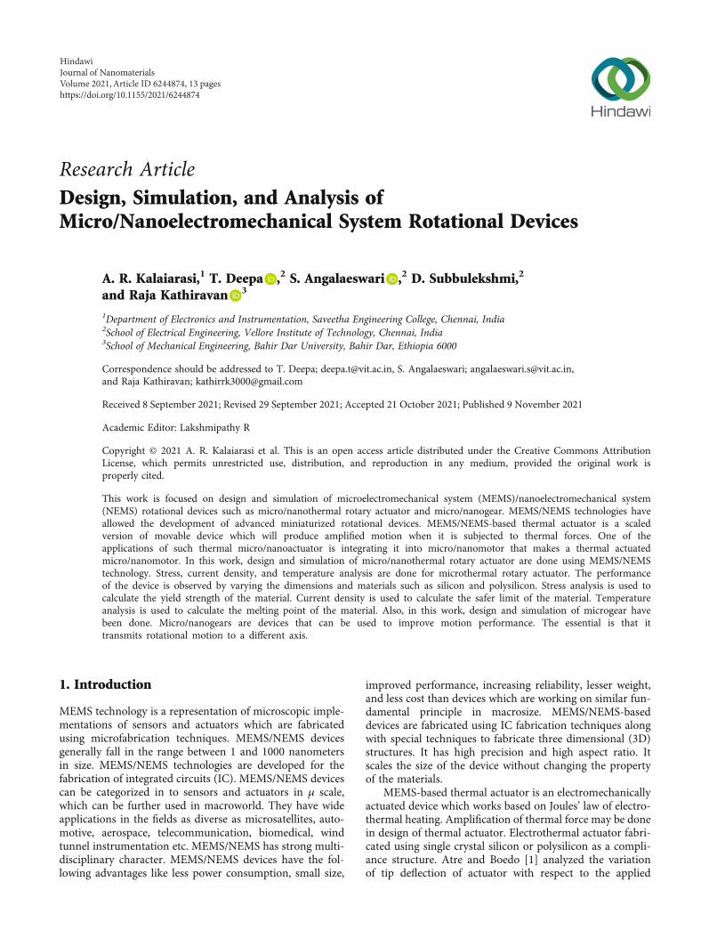
Figure 5: Temperature analysis of silicon (circular disc 5 μm).
298
298
Figure 6: Temperature analysis of silicon (square arm 10μm).
3Journal of Nanomaterials
voltage. Kim et al. [20] designed and fabricated the multilay-ered structure with platinum heater. Ni-Co-based flexiblesubstrate as thermal bimorph actuators and thermal insula-tion (isolation) layers are also employed. Ulkir [21] designedbidirectional electrothermal actuator which displaces in twodirections. Authors compared the fabrication process of 2photon polymerization (2PP) and digital light processing(DLP) methods, which are 3D printing techniques. Steineret al. [22] studied the relation between actuator area anddeflection distance based on V-shaped Chevron type beams.
Duzng [23] modeled the V-shaped thermal actuatorusing ordinary differential equations. Author studied aboutthe thermal inertia of the system, if the applied voltage isin the form of square pulse, the output is in form of concavetrapezium. Li et al. [24] discussed the application of thermalactuator in testing the fracture strength of thin films. Voltageis applied to thermal actuator, which creates the thermal
expansion; due to thermal expansion force that is createdwhich is used to fracture the test structure. Suryanarayananet al. [25] compared experimental results, and simulationresults are correlated using back propagation neural net-work. Simulation results fitted with neural network providea cost-effective model for V-shaped thermal actuator. Gonget al. [26] studied the relation between length of flexureand thermal deflection of bimorph thermal actuator. Theauthor proposes that the length of flexure would not increasethe stress on the arm length, and it also increases the lifetimeof actuator. López-Walle et al. [27] discussed heat transfercharacteristics that are important in improving the perfor-mance of thermal actuator. Kim et al. [28] discussed theapplication of bimorph thermal actuators in rotation controlof micromirrors. Two bimorph actuators produce verticaldisplacement of 25μm at 10V, which rotates micromirrorby 20°.
298Surface: Temperature (K)
298
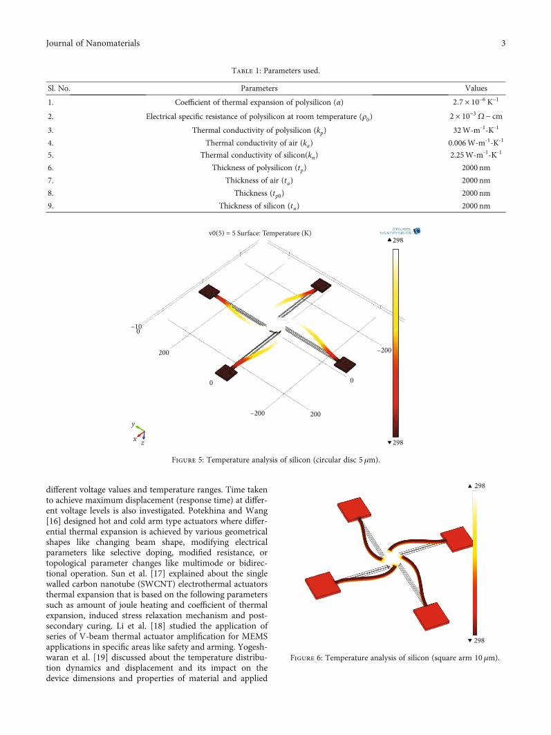
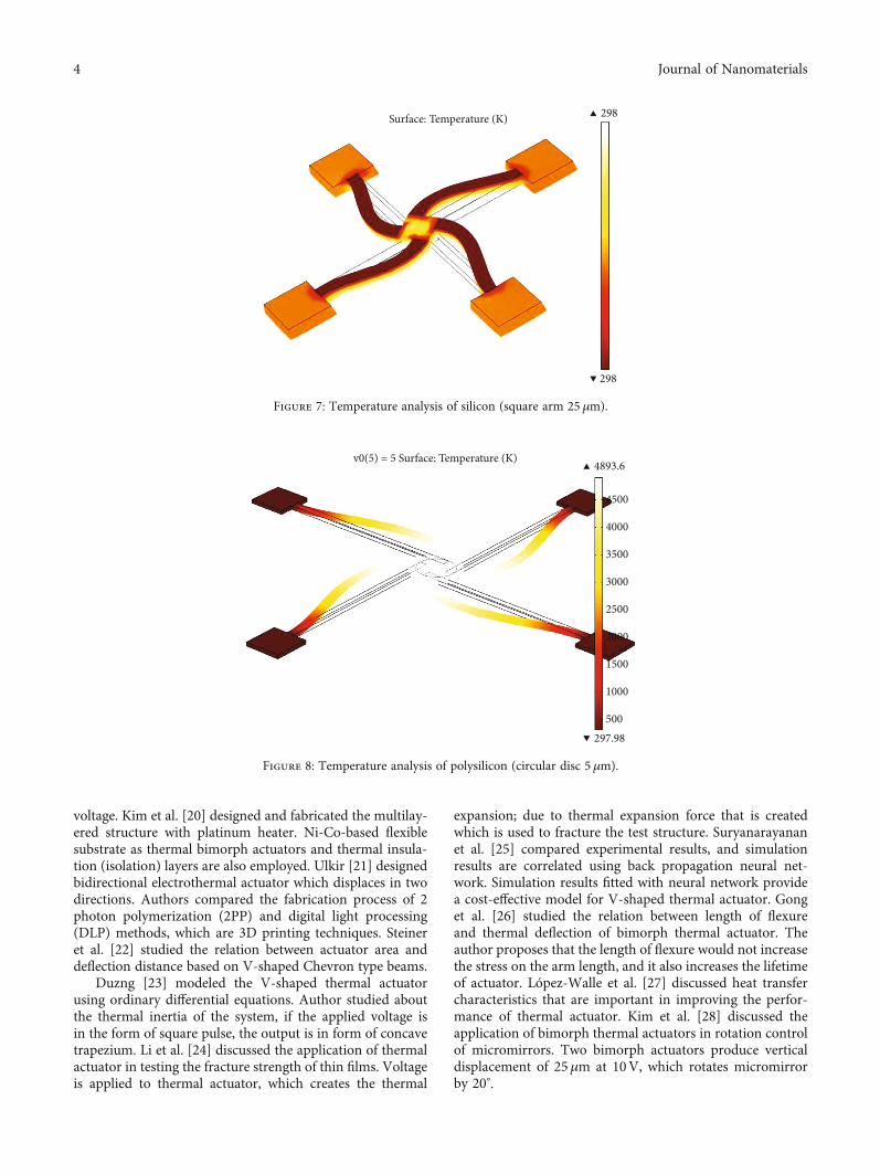
Figure 7: Temperature analysis of silicon (square arm 25 μm).
v0(5) = 5 Surface: Temperature (K) 4893.6
4500
4000
3500
3000
2500
2000
1500
1000
500297.98
Figure 8: Temperature analysis of polysilicon (circular disc 5 μm).
4 Journal of Nanomaterials
2. Importance of Microthermal Rotary Actuator
Electrostatic actuation and thermal actuation are methods toobtain actuation in MEMS. This method of actuations isvery popular since this actuation provides simplicity, fastactuation rates, and low power consumption, and it uses sil-icon as its material. This type of actuation method is a com-mon method of driving MEMS devices because it iscompatible with microfabrication.
Thermal microactuators have the following advantageslike higher force, lesser operating voltages, and less suscepti-bility to adhesion failures compared to electrostatic actua-tors. Microthermal actuators do require more power, andtheir switching speeds are limited by cooling times. It pro-duces higher displacement and higher force than electro-static actuators.
3. Types of Microthermal Rotary Actuator
3.1. A-Symmetric (Bimorph). A bimorph is a microcantileverbased thermal actuator used as an actuator or sensor whichconsists of two metal layers. In some applications, it alsohas a passive layer between the two active layers. The termbimorph is most commonly used with thermal bimorphs.The first theory about the bending of thermally actuatedbimorph was given by Stoney. In Figure 1, schematic dia-gram of A-symmetric (bimorph) is shown. It has generallya single material. The deflection is produced here due toasymmetry in the shape. This type of thermal actuator is alsocalled as hot-cold beam actuator.
3.2. Symmetric (Bent Beam, Chevron). Chevron-shaped actu-ators are one of the most popular actuators in the MEMS
Surface: Temperature (K)
2
1.5
1
0.5
273
2.2305×107
×107
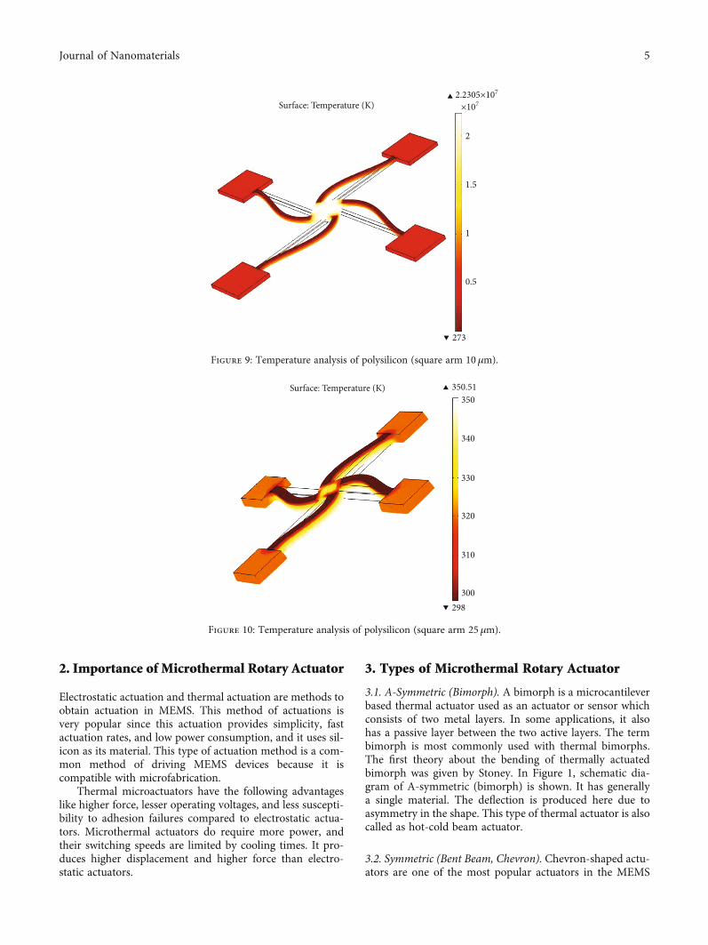
Figure 9: Temperature analysis of polysilicon (square arm 10 μm).
Surface: Temperature (K)350
340
330
320
310
300
350.51
298
Figure 10: Temperature analysis of polysilicon (square arm 25 μm).
5Journal of Nanomaterials
community (also called V-beam thermal actuator). Its prin-ciple is based on the thermal expansion of a single materialto generate the motion, which is amplified using differentgeometric constraints. The V-beam thermal actuators arecapable of producing high output force for low operatingvoltage. The output force (displacement) depends on theinclination of the beam. In Figure 2, Chevron beam actuatoris shown.
3.3. Designing of Microthermal Rotary Actuator. Designingof microthermal rotary actuator is done using structuralmechanics. For designing the microthermal rotary actuator,the important parameters used are materials and dimen-sions. Finite element method (FEM) software used to designthe thermal actuator. Here, COMSOL is used for simulation.The actuator’s operation involves three coupled physics phe-
nomena: electric current conduction, heat conduction withheat generation, and structural stresses and strains due tothermal expansion. In COMSOL, the joule heating modeluses the heat equation given in equation as the mathematicalmodel for heat transfer in solids.
3.3.1. Dimensions. Microthermal rotary actuator is doneusing structural differ from varying its length and shape ofthe cold disc. Length of the hot arm is varies from 500nmto 2500 nm. Height of the cold beam is 500nm, and thediameter of the cold beam is 200 nm. Figure 3 shows themicrothermal rotary actuator structure.
3.3.2. Materials. Materials used for designing of microther-mal rotary actuator are silicon and poly silicon. Each mate-rial has a unique property which makes them to use indesigning the microthermal rotary actuator.
v0(5) = 5 Surface: Temperature (K)298
298
200
0
–200–200
0
200
00
xz
y
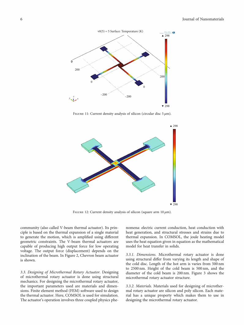
Figure 11: Current density analysis of silicon (circular disc 5μm).
298
298
Figure 12: Current density analysis of silicon (square arm 10μm).
6 Journal of Nanomaterials
3.4. Theoretical Analysis
3.4.1. Electrothermal Analysis. The above Figure 4 shows the1D of actuator. According to joule’s heating,
rate of heat input = rate of heat going out
Qin +Qjoule =Qout,arm +Qout,sub: ð1Þ
Since
Qin = −kpwtpdTdx
� �x
;Qjoule = J2ρwtpdx,
Qout,arm = −kpwtpdTdx
� �x+dx
;Qout,sub = SdxwT − T sub
RT,
ð2Þ
where T is the temperature at any given location of theactuator. Tsub is the substrate temperature. ρ is the resistivityof material. kp is the thermal conductivity of material. J isthe current density of hot arm or cold disc. S is the shape fac-tor. RT is the thermal resistance between the device and thesubstrate.
Substitute above values in Equation (1), and we get
−kpwtpdTdx
� �x
+ J2ρwtpdx =
−kpwtpdTdx
� �x+dx
+ SdxwT − T sub
RT
ð3Þ
Thermal resistance between the device and the substrateis given by
Rt =taka
+tp0kp0
+ tnkn
, ð4Þ
where ta, tp0 , and tn are the thickness of the element
above the polysilicon layer, thickness of polysilayer, andthickness of silicon layer. ka, kp0, and kn are the thermal con-ductivity values of air, polysilicon and silicon, respectively.
Substitute the needed values to Equation (4) fromTable 1. After calculating thermal resistance obtained, itisRt = 7:7205 × 10−5.
Current density is the amount of current by unit area. Thecurrent density of hot arm and cold disc is calculated from
Jh =I
wptp, ð5Þ
Jc = :Using the above equation, the calculated current density
value is Jh = 7:5 × 10¹¹ and Jc = 15 × 1011. The calculatedvalues almost match with the values obtained from simula-tion; so, the device can be able to fabricate.
Shape factor of the hot arm is given by
S =tpwh
2tatp
+ 1" #
+ 1: ð6Þ
The obtained shape factor is S = 1:6 μm.Resistivity is calculated by using the Van der paw
method:
ρ = 2:971 × 10−2� �
T + 20:858: ð7Þ
At room temperature, the resistivity is ρ = 21:5 μΩ.Simplifying the Equation (3), we get
d2T xð Þdx2
= S T xð Þ − Tsubð ÞkptpRT
−J2ρkp
: ð8Þ
3.4.2. Rotational Analysis.
ΔLh = Rδ: ð9Þ
300
310
320
330
340
350350.51
298
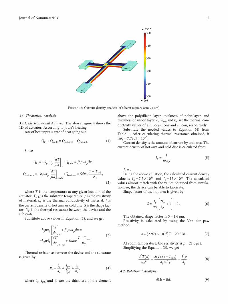
Figure 13: Current density analysis of silicon (square arm 25μm).
7Journal of Nanomaterials
where R is the radius of the disc. ΔLh is the total expan-sion of the free end. δ is the angle of rotation.
Here, taking R as 10 and the angle of rotation as 3.90,then ΔLh = 3900 nm.
4. Results and Discussion
4.1. Stress Analysis. Stress analysis is conducted to find thedeformation of microthermal rotary actuator for the givenpressure. Normal pressure for the stress analysis is about7GPa which is the yield strength of the silicon materialand 8.4GPa for poly silicon.
4.2. Von Mises Stress Analysis. This analysis is used in micro-thermal rotary actuator. So, when the stress is given, the
material starts to yield after the critical value of yieldstrength which depends on von Mises stress.
4.3. Current Density Analysis. Current density is defined asthe amount of charge per unit time that flows through a unitarea of a chosen cross-section. Here, expected current den-sity of a MEMS/NEMS thermal rotary actuator should beless than the electric field for fabrication.
4.4. Temperature Analysis. Temperature is a physical prop-erty of matter that quantitatively defines hot and cold. It isthe indication of thermal energy present in all matter, whichis the source of occurrence of heat, which is a flow of energy,when a body is in contact with another one which is cooler.The obtained temperature plot should be less than meltingpoint of the material used there, and the devices is simulatedunder room temperature 298K.
298
350.51
300
310
320
330
340
350
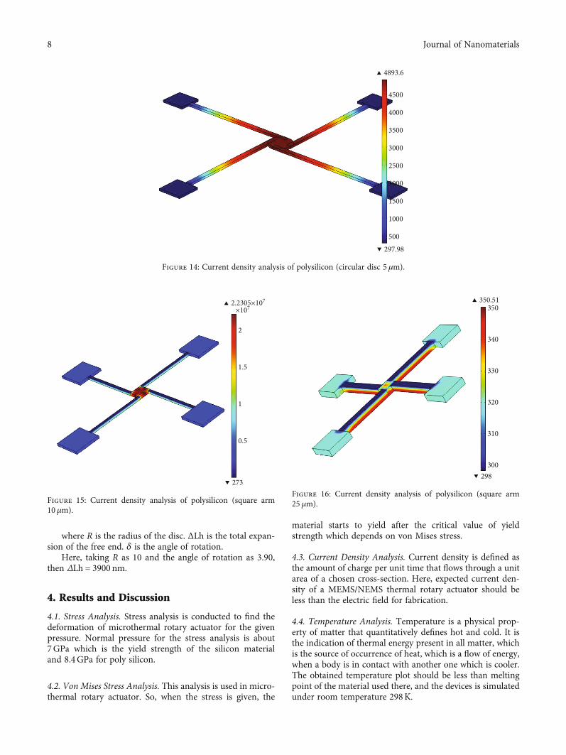
Figure 16: Current density analysis of polysilicon (square arm25 μm).
273
2.2305×107×107
2
1.5
1
0.5
Figure 15: Current density analysis of polysilicon (square arm10μm).
4500
4000
3500
3000
2500
3000
1500
1000
500
4893.6
297.98
Figure 14: Current density analysis of polysilicon (circular disc 5 μm).
8 Journal of Nanomaterials
4.4.1. Temperature Analysis. Figure 5 shows the temperatureplot of silicon actuator at room temperature. Here, centerarm experiences high heat because the current value is high.Figure 6 shows the temperature of silicon actuator at roomtemperature.. If the area of the centre arm is increased, tem-perature is high but less compared to previous square arm of10μm. Figure 7 shows the temperature of silicon actuator.The obtained value is 298K. Polysilicon and silicon arebehaving similar in temperature analysis. If the square armsize is 5μm, temperature developed is so high. Figure 8shows the temperature of polysilicon actuator. The obtainedvalue varies from 297.98K to 4893.6K. As discussed insilicon-based rotary actuator, here, also, if size of arm isincrease, then temperature rise is reduced.
Figure 9 shows the temperature of polysilicon actuator.The obtained value varies from 273K to 2:2305 × 107.Figure 10 shows the temperature of polysilicon actuator.Here, the thickness is increased; hence, heat developed isdecreased. The obtained value varies from 298K to 350.51K.
4.4.2. Current Density Analysis. Figure 11 shows the currentdensity of silicon actuator. The obtained value is 298.Figure 12 shows the current density of Silicon actuator.The value of bending is 298. Figure 13 shows the currentdensity of silicon actuator. The value of bending varies from298 to 350.51. Figure 14 shows the current density of poly Siactuator. The value of bending varies from 297.98 to 4893.6.Figure 15 shows the current density of poly silicon actuator.
70
60
50
40
30
20
10
0
v0(5) = 5 Surface: Total displacement (𝜇m)
200
0
–200–200
0
00
200
xzy
7.9144×10–3
×10–4
0
Figure 17: Von Mises stress of silicon (circular disc 5μm).
Surface: Total displacement (𝜇m)8.4303×10⁻³
80
70
60
50
40
30
20
10
0
×10–4
0
Figure 18: Von Mises stress of silicon (square arm 10 μm).
9Journal of Nanomaterials
The value of bending varies from 272 to 2:2307 × 107.Figure 16 shows the current density of poly silicon actuator.The value of bending varies from 272 to 350.
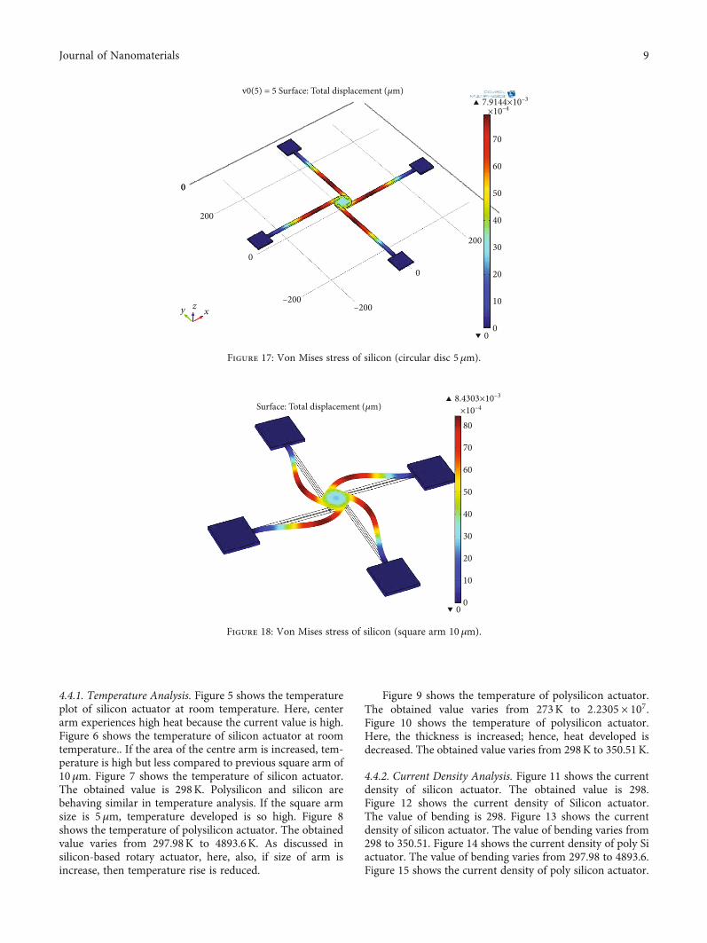
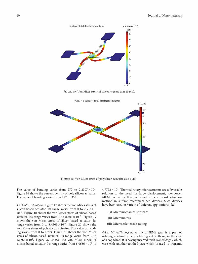
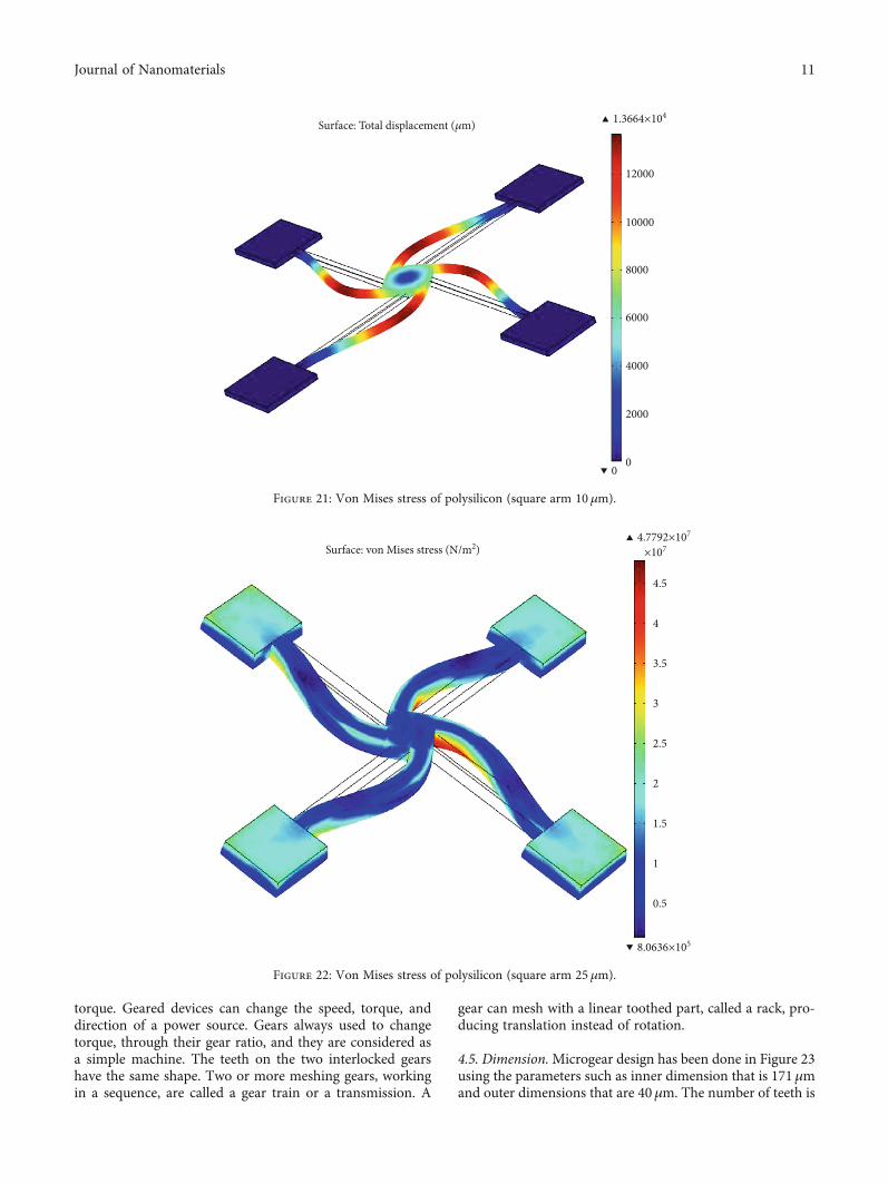
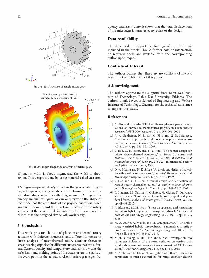
4.4.3. Stress Analysis. Figure 17 shows the von Mises stress ofsilicon-based actuator. Its range varies from 0 to 7:9144 ×10−9. Figure 18 shows the von Mises stress of silicon-basedactuator. Its range varies from 0 to 8:403 × 10−9. Figure 19shows the von Mises stress of silicon-based actuator. Itsrange varies from 0 to 8:4303 × 10−8. Figure 20 shows thevon Mises stress of polysilicon actuator. The value of bend-ing varies from 0 to 4.709. Figure 21 shows the von Misesstress of silicon-based actuator. Its range varies from 0 to1:3664 × 104. Figure 22 shows the von Mises stress ofsilicon-based actuator. Its range varies from 8:0636 × 105 to
4:7792 × 107. Thermal rotary microactuators are a favorablesolution to the need for large displacement, low-powerMEMS actuators. It is confirmed to be a robust actuationmethod in surface micromachined devices. Such deviceshave been used in variety of different applications like
(i) Micromechanical switches
(ii) Micromotors
(iii) Microscale tensile testing
4.4.4. Micro/Nanogear. A micro/NEMS gear is a part ofrotating machine which is having cut teeth or, in the caseof a cog wheel, it is having inserted teeth (called cogs), whichwire with another toothed part which is used to transmit
v0(5) = 5 Surface: Total displacement (𝜇m)
0
0.5
1
1.5
2
2.5
3
3.5
4
4.5
4.709
0
Figure 20: Von Mises stress of polysilicon (circular disc 5 μm).
Surface: Total displacement (𝜇m)
80
70
60
50
40
30
20
10
00
8.4303×10–3
×10–4
Figure 19: Von Mises stress of silicon (square arm 25 μm).
10 Journal of Nanomaterials
torque. Geared devices can change the speed, torque, anddirection of a power source. Gears always used to changetorque, through their gear ratio, and they are considered asa simple machine. The teeth on the two interlocked gearshave the same shape. Two or more meshing gears, workingin a sequence, are called a gear train or a transmission. A
gear can mesh with a linear toothed part, called a rack, pro-ducing translation instead of rotation.
4.5. Dimension.Microgear design has been done in Figure 23using the parameters such as inner dimension that is 171μmand outer dimensions that are 40μm. The number of teeth is
Surface: Total displacement (𝜇m) 1.3664×10⁴
12000
10000
8000
6000
4000
2000
00
Figure 21: Von Mises stress of polysilicon (square arm 10 μm).
Surface: von Mises stress (N/m2)
0.5
1
1.5
2
2.5
3
3.5
4
4.5
4.7792×107
×107
8.0636×10⁵
Figure 22: Von Mises stress of polysilicon (square arm 25 μm).
11Journal of Nanomaterials
17μm, its width is about 14μm, and the width is about50μm. This design is done by using material called cast iron.
4.6. Eigen Frequency Analysis. When the gear is vibrating ateigen frequency, the gear structure deforms into a corre-sponding shape which is called eigen mode. An eigen fre-quency analysis of Figure 24 can only provide the shape ofthe mode, not the amplitude of the physical vibration. Eigenanalysis is done to find the structural behavior of the rotaryactuator. If the structure deformation is less, then it is con-cluded that the designed device will work safely.
5. Conclusion
This work presents the out of plane microthermal rotaryactuator with different structures and different dimensions.Stress analysis of microthermal rotary actuator shows itsstress bearing capacity for different structures that are differ-ent. Current density and temperature analysis show that thesafer limit and melting point of the actuator are the same atthe every point in the actuator. Also, in microgear eigen fre-
quency analysis is done, it shows that the total displacementof the microgear is same as every point of the design.
Data Availability
The data used to support the findings of this study areincluded in the article. Should further data or informationbe required, these are available from the correspondingauthor upon request.
Conflicts of Interest
The authors declare that there are no conflicts of interestregarding the publication of this paper.
Acknowledgments
The authors appreciate the supports from Bahir Dar Insti-tute of Technology, Bahir Dar University, Ethiopia. Theauthors thank Saveetha School of Engineering and VelloreInstitute of Technology, Chennai, for the technical assistanceto support this study.
References
[1] A. Atre and S. Boedo, “Effect of Thermophysical property var-iations on surface micromachined polysilicon beam flexureactuator,” NSTI-Nanotech, vol. 2, pp. 263–266, 2004.
[2] A. A. Geisberger, N. Sarkar, M. Ellis, and G. D. Skidmore,“Electrothermal properties and modeling of polysilicon micro-thermal actuators,” Journal of Microelectromechanical Systems,vol. 12, no. 4, pp. 513–523, 2003.
[3] S. Heo, G. H. Yoon, and Y. Y. Kim, “The robust design formicro electro-thermal actuators,” in Smart Structures andMaterials 2004: Smart Electronics, MEMS, BioMEMS, andNanotechnology (Vol. 5389, pp. 241-247), International Societyfor Optics and Photonics, 2004.
[4] Q.-A. Huang and N. K. S. Lee, “Analysis and design of polysi-licon thermal flexure actuator,” Journal of Micromechanics andMicroengineering, vol. 9, no. 1, pp. 64–70, 1999.
[5] S. Heo and Y. Y. Kim, “Optimal design and fabrication ofMEMS rotary thermal actuators,” Journal of Micromechanicsand Microengineering, vol. 17, no. 11, pp. 2241–2247, 2007.
[6] B. Haefner, M. Quiring, J. Gullasch, G. Glaser, T. Dmytruk,and G. Lanza, “Finite element simulation for quality depen-dent lifetime analysis of micro gears,” Science Direct, vol. 31,pp. 41–46, 2015.
[7] A. Islam and M. M. Islam, “Stress on spur gear and simulationfor micro hybrid systems by Ansys workbench,” Journal ofMechanical and Energy Engineering, vol. 3, no. 1, pp. 25–30,2019.
[8] M. A. Arefin, A. Mallik, and M. Asfaquzzaman, “Renewableenergy–assisted hybrid three-wheeler: a numerical investiga-tion,” Advances in Mechanical Engineering, vol. 10, no. 12,Article ID 168781401881437, 2018.
[9] X. Jin, Y. Wang, W. Ju, J. He, and S. Xie, “Investigation intoparameter influence of upstream deflector on vertical axiswind turbines output power via three-dimensional CFD simu-lation,” Renewable Energy, vol. 115, pp. 41–53, 2018.
[10] A. Arefin and R. Islam, “Investigation of different validationparameters of micro gas turbine for range extender electric
–1–5
–5
5
0
05
–0.5×105
×104
×104y
z
x
00.5
Figure 23: Structure of single microgear.
Eigenfrequency = 3610.605676surface: Total displacement (𝜇m) 2.7405×106
×106
0 0
0.5
1
1.5
2
2.5
Figure 24: Eigen frequency analysis of micro gear.
12 Journal of Nanomaterials
truck,” International Journal of Engineering, vol. 31, no. 10,pp. 1782–1788, 2018.
[11] S. M. Karbosi, M. Shamshrisar, M. Naraghi, and M. Manoufi,“Optimal design analysis of electrothermally driven microac-tuators,” Microsystem Technologies, vol. 16, no. 7, pp. 1065–1071, 2010.
[12] C. Lo, M. Lin, and C. Hwan, “Modeling and analysis of electro‐thermal microactuators,” Journal of the Chinese Institute ofEngineer, vol. 32, no. 3, pp. 351–360, 2009.
[13] D. Veeman, M. S. Sai, P. Sureshkumar et al., “Additivemanufacturing of biopolymers for tissue engineering andregenerative medicine: an overview, potential applications,advancements, and trends,” International Journal of PolymerScience, vol. 2021, Article ID 4907027, 20 pages, 2021.
[14] R. S. Chiorean, M. C. Dudescu, and M. Pustan, “Analyticaland numerical study on the maximum force developed by aV-beam thermal actuator,” Procedia Technology, vol. 12,pp. 359–363, 2014.
[15] S. Wang, Y. Hao, and S. Liu, “The design and analysis of aMEMS electrothermal actuator,” Journal of Semiconductors,vol. 36, no. 4, p. 044012, 2015.
[16] A. Potekhina and C. Wang, “Review of Electrothermal Actua-tors and Applications,” MDPI Actuators, vol. 8, no. 4, 2019.
[17] Y. Sun, B. D. Leaker, J. E. Lee, R. Nam, and H. E. Naguib,“Shape programming of polymeric based electrothermal actu-ator (ETA) via artificially induced stress relaxation,” ScientificReports, vol. 9, no. 1, article 11445, 2019.
[18] X. Li, Y. Zhao, T. Hu et al., “Design of a large displacementthermal actuator with a cascaded V-beam amplification forMEMS safety-and-arming devices,”Microsystem Technologies,vol. 21, no. 11, pp. 2367–2374, 2015.
[19] S. Yogeshwaran, L. Natrayan, S. Rajaraman, S. Parthasarathi,and S. Nestro, “Experimental investigation on mechanicalproperties of epoxy/graphene/fish scale and fermented spinachhybrid bio composite by hand lay-up technique,” MaterialsToday: Proceedings, vol. 37, no. 2, pp. 1578–1583, 2021.
[20] S. Kim, W. Kim, and Y. Kim, “Design and performanceevaluation of thin-film actuators based on flexible Ni-Cosubstrates,” Micro and Nano Systems Letters, vol. 8, no. 1,2020.
[21] O. Ulkir, “Design and fabrication of an electrothermal MEMSmicro-actuator with 3D printing technology,” MaterialsResearch Express, vol. 7, no. 7, 2020.
[22] H. Steiner, F. Keplinger, J. Schalko, W. Hortschitz, andM. Stifter, “Highly efficient passive thermal micro-actuator,”Journal of Microelectromechanical Systems, vol. 24, no. 6,pp. 1981–1988, 2015.
[23] N. T. Duzng, “Modeling and simulation of V-shaped thermalactuator,” American Journal of Engineering Research, vol. 7,no. 4, pp. 222–227, 2018.
[24] M. Li, Z. Zhou, L. Yi, X. Wang, and S. Adnan, “Design of a teststructure based on chevron-shaped thermal actuator for in-situ measurement of the fracture strength of MEMS thinfilms,” Nanotechnology and Precision Engineering, vol. 2,no. 4, pp. 163–168, 2019.
[25] R. Suryanarayanan, V. G. Sridhar, L. Natrayan et al.,“Improvement on mechanical properties of submerged fric-tion stir joining of dissimilar tailor welded aluminum blanks,”Advances in Materials Science and Engineering, vol. 2021, Arti-cle ID 3355692, 6 pages, 2021.
[26] Y. J. Gong, F. Zhao, H. Y. Xiang, and L. Zhang, “Thermal anal-ysis and simulation of MEMS thermal actuator for food indus-try,” Advanced Materials Research, vol. 179-180, pp. 392–397,2011.
[27] B. López-Walle, M. Gauthier, and N. Chaillet, “Dynamicmodelling for thermal micro-actuators using thermal net-works,” International Journal of Thermal Sciences, vol. 49,no. 11, pp. 2108–2116, 2010.
[28] D. H. Kim, K. S. Oh, and S. Park, “Design and analysis of atwisting-type thermal actuator for micromirrors,” Journal ofMechanical Science and Technology, vol. 23, no. 6, pp. 1536–1543, 2009.
13Journal of Nanomaterials