Embed Size (px)
Citation preview
Design ReviewGroup members:
Ed BarnardLizzie HagerJenny Lichter
Kevin McComber
3-11-04
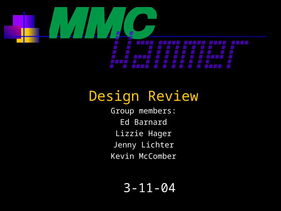
Overview
Goal and Processing Method Ceramic Preform Pressure Vessel Calculations Prototype Mold Design Expected and Threshold Pressures Infiltration ASME Standards for Hammers Methods of Characterization Risks
Halstead
Goal
The goal of our project is to manufacture a light-weight, high fracture toughness hammer using metal matrix composites.
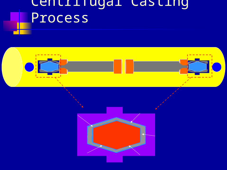
Centrifugal Casting Process
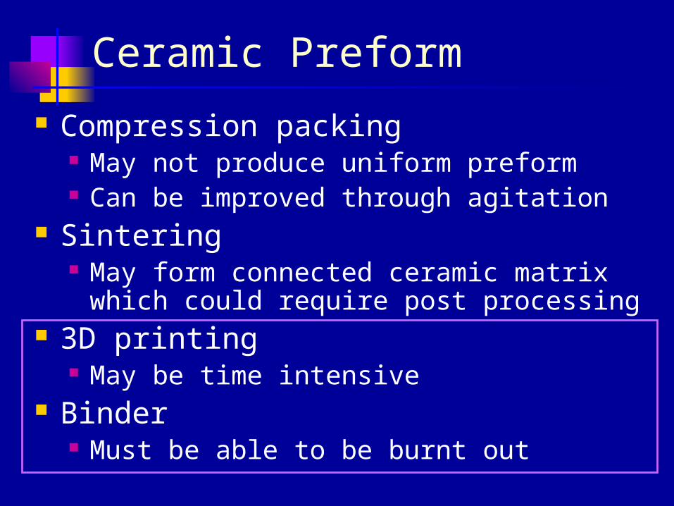
Ceramic Preform
Compression packing May not produce uniform preform Can be improved through agitation
Sintering May form connected ceramic matrix which
could require post processing 3D printing
May be time intensive Binder
Must be able to be burnt out
Numerical Simulations
Monte Carlo Simulations Were considered to model packing density
of ceramic powders Assume spherical particles Our particles are not spherical
Wannasin
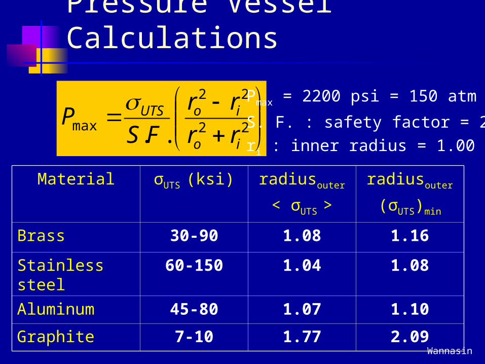
Pressure Vessel Calculations
22
22
max .. io
ioUTS
rr
rr
FSP
Pmax = 2200 psi = 150 atm
S. F. : safety factor = 2ri : inner radius = 1.00 inch
Material σUTS (ksi) radiusouter
< σUTS >
radiusouter
(σUTS)min
Brass 30-90 1.08 1.16
Stainless steel 60-150 1.04 1.08
Aluminum 45-80 1.07 1.10
Graphite 7-10 1.77 2.09
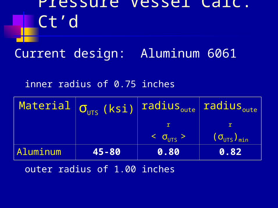
Pressure Vessel Calc. Ct’d
Current design: Aluminum 6061
inner radius of 0.75 inches
outer radius of 1.00 inches
Material σUTS (ksi) radiusouter
< σUTS >
radiusouter
(σUTS)min
Aluminum 45-80 0.80 0.82
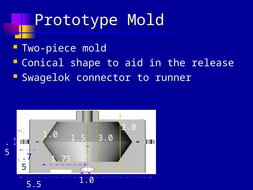
Prototype Mold
Two-piece mold Conical shape to aid in the release Swagelok connector to runner
5.5
1.0 1.5 3.02.0
1.0
1.75.75
.5
Release from mold
Boron Nitride Spray Coating
Graphite powder
Breakaway ceramic TiC – small particle size Need a binder
Wannasin
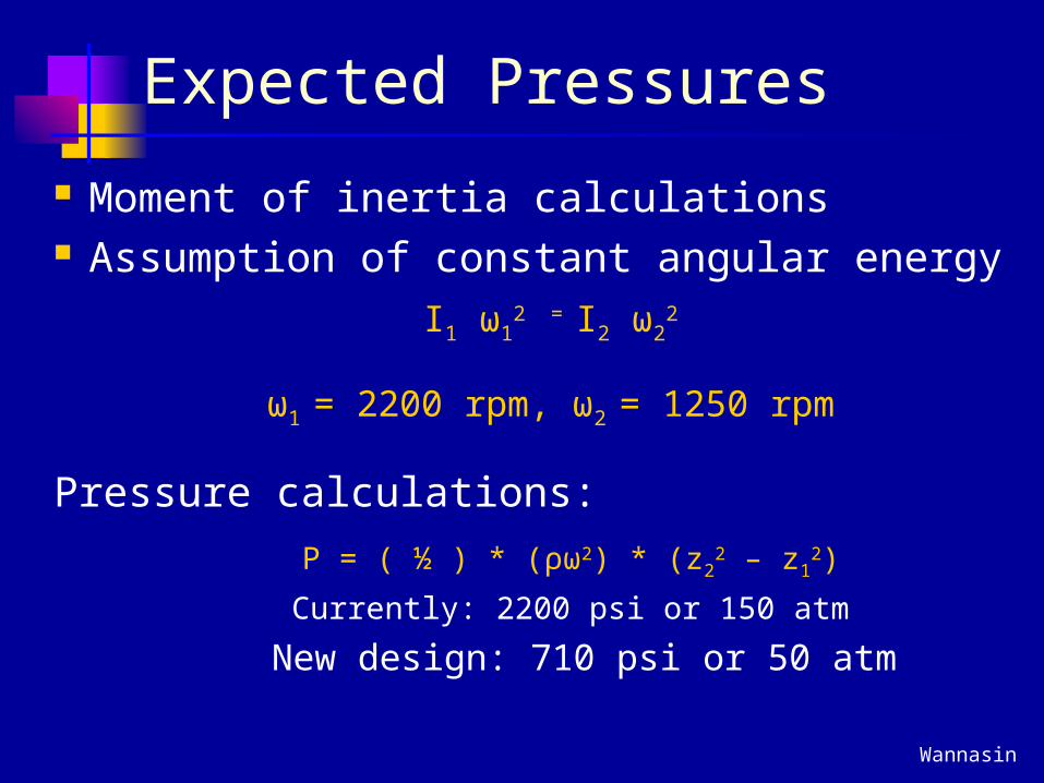
Expected Pressures
Moment of inertia calculations Assumption of constant angular energy
I1 ω12 = I2 ω2
2
ω1 = 2200 rpm, ω2 = 1250 rpm
Pressure calculations:
P = ( ½ ) * (ρω2) * (z22 – z1
2)
Currently: 2200 psi or 150 atm
New design: 710 psi or 50 atm
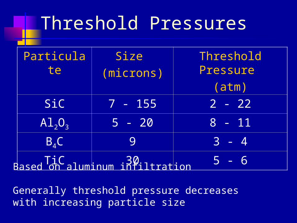
Threshold Pressures
Particulate Size (microns)
Threshold Pressure
(atm)
SiC 7 - 155 2 - 22
Al2O3 5 - 20 8 - 11
B4C 9 3 - 4
TiC 30 5 - 6Based on aluminum infiltration
Generally threshold pressure decreases with increasing particle size
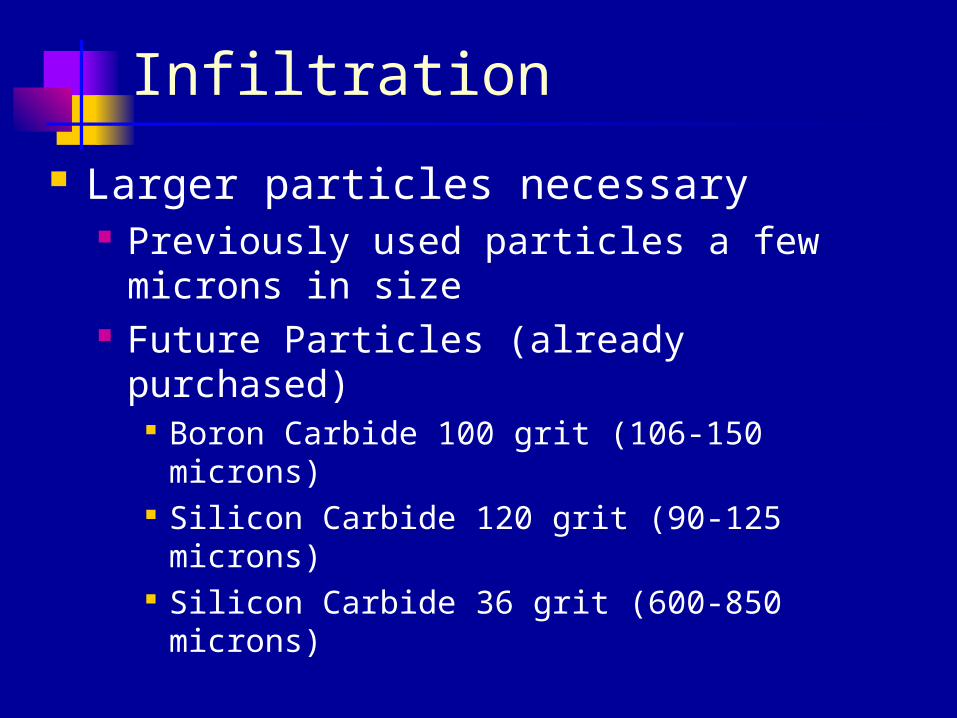
Infiltration
Larger particles necessary Previously used particles a few microns in
size Future Particles (already purchased)
Boron Carbide 100 grit (106-150 microns) Silicon Carbide 120 grit (90-125 microns) Silicon Carbide 36 grit (600-850 microns)
Halstead
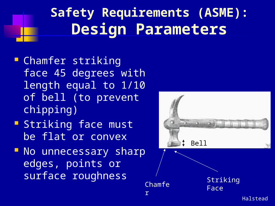
Safety Requirements (ASME):Design Parameters
Chamfer striking face 45 degrees with length equal to 1/10 of bell (to prevent chipping)
Striking face must be flat or convex
No unnecessary sharp edges, points or surface roughness
Striking FaceChamfer
Bell
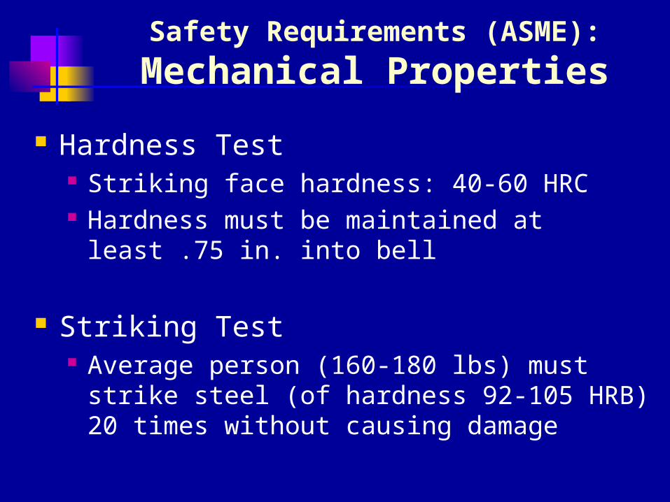
Safety Requirements (ASME):
Mechanical Properties
Hardness Test Striking face hardness: 40-60 HRC Hardness must be maintained at least .75
in. into bell
Striking Test Average person (160-180 lbs) must strike
steel (of hardness 92-105 HRB) 20 times without causing damage
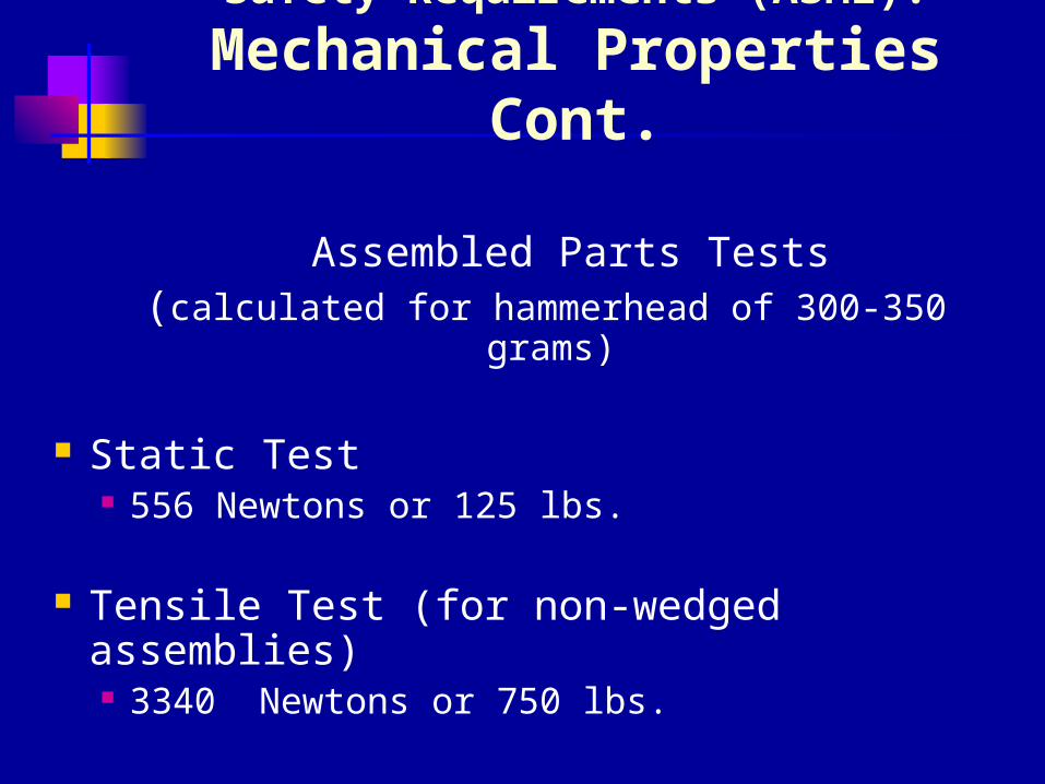
Safety Requirements (ASME):
Mechanical Properties Cont.
Assembled Parts Tests (calculated for hammerhead of 300-350 grams)
Static Test 556 Newtons or 125 lbs.
Tensile Test (for non-wedged assemblies) 3340 Newtons or 750 lbs.
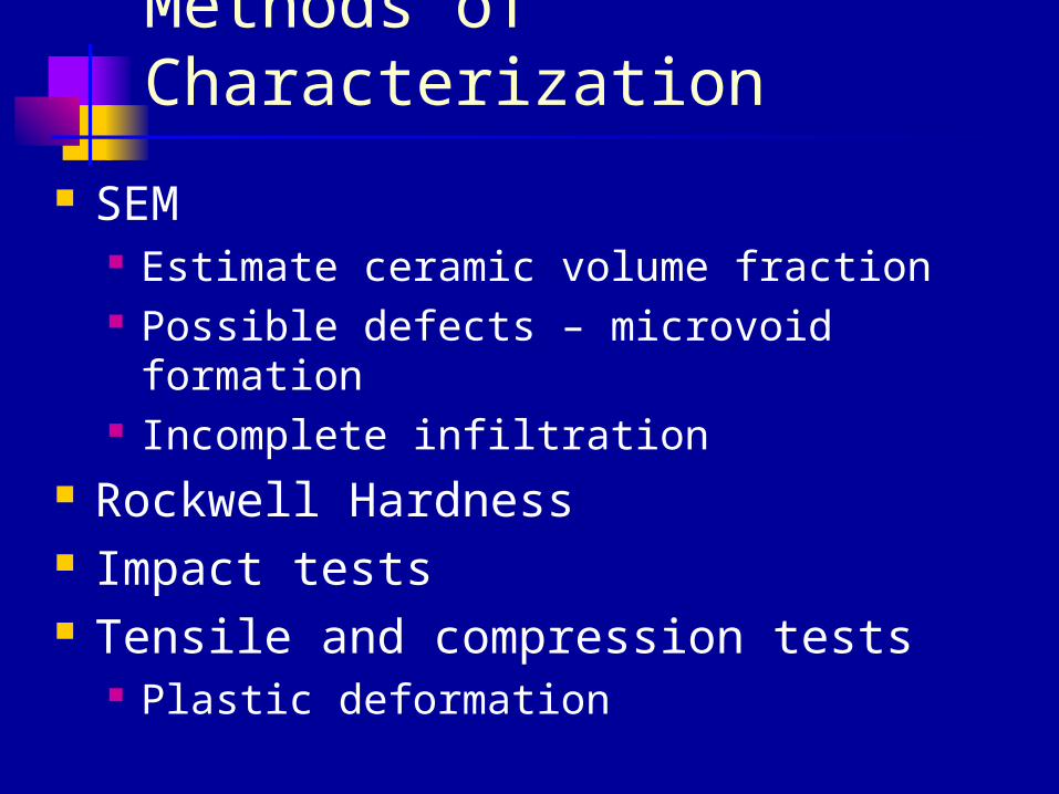
Methods of Characterization
SEM Estimate ceramic volume fraction Possible defects – microvoid formation Incomplete infiltration
Rockwell Hardness Impact tests Tensile and compression tests
Plastic deformation
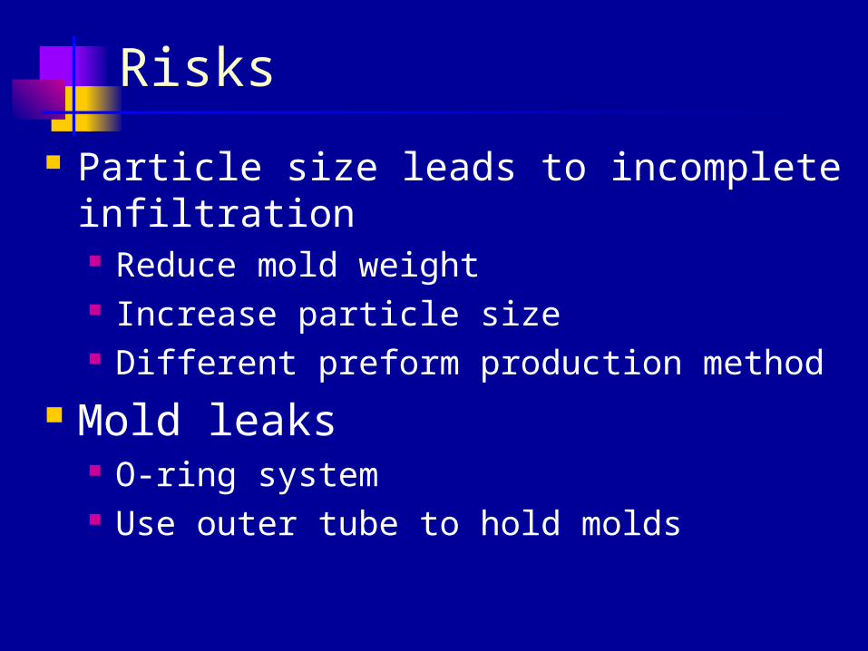
Risks
Particle size leads to incomplete infiltration Reduce mold weight Increase particle size Different preform production method
Mold leaks O-ring system Use outer tube to hold molds
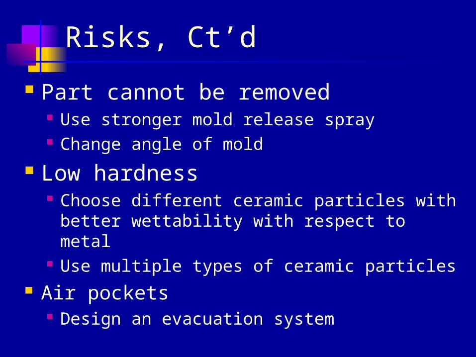
Risks, Ct’d
Part cannot be removed Use stronger mold release spray Change angle of mold
Low hardness Choose different ceramic particles with
better wettability with respect to metal Use multiple types of ceramic particles
Air pockets Design an evacuation system
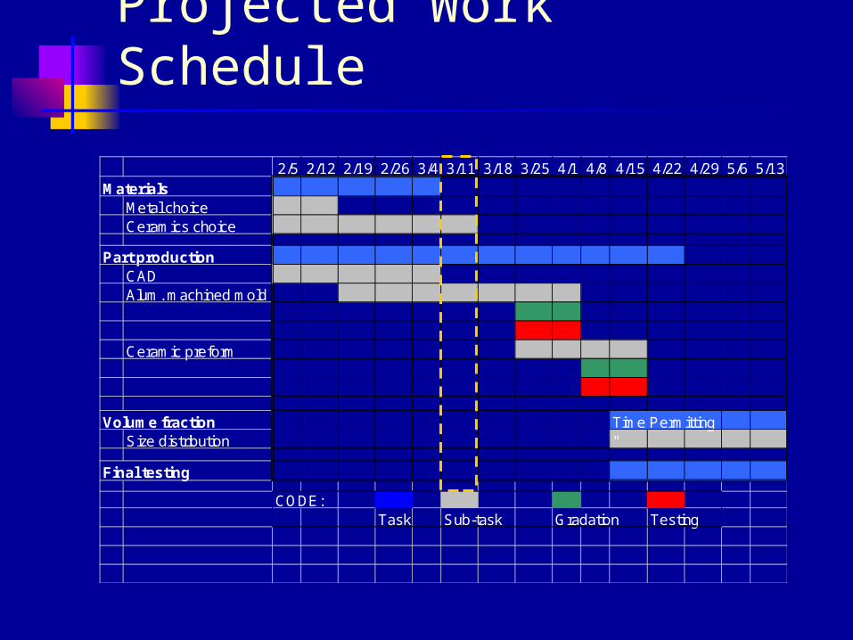
Projected Work Schedule
2/5 2/12 2/19 2/26 3/4 3/11 3/18 3/25 4/1 4/8 4/15 4/22 4/29 5/6 5/13Materials
Metal choiceCeramics choice
Part productionCADAlum. machined mold
Ceramic preform
Volume fraction Time PermittingSize distribution "
Final testing
CODE:Task Sub-task Gradation Testing
Works Cited
Halstead, Gary. “Pictures from Dictionaire Paisonné du Mobilier Français.” Accessed 24
February 2004. Medieval and Renaissance Woodworking. 2003.
<http://www.medievalwoodworking.com/vld_tools.htm >.
Wannasin, Jessada. PhD Thesis. March 2004.