Embed Size (px)
Citation preview

Tin Lizzie 18 Assembly Instructions
Revision: 07/29/16

7 Disassemble the Machine7 Remove the Handle Bars, Mount, PCB box9 Remove Hand Wheel Cover9 Remove the Motor Belt10 Remove the Motor10 Remove the Rocker Arm Covers11 Remove the Handwheel
1
3 Before You Begin5 Aides5 Tools6 Perfect Stitch Parts
12 Modify the Machine 12 Prepare Drill Templates12 Front Display13 Control Box14 Rear Display15 Rear Power Supply16 Motor
2
17 Reassemble the Machine17 Attach Handlebars18 Attach Android Display19 Attach Linux Display20 Feed Handlebar wires21 Attach the Handwheel21 Attach the Motor 24 Attach Cables to the Control Box28 Mount the Index Sensor 31 Attach the control Box31 Attach the Rear Display32 Attach the Rear Handlebars32 Plug in Rear Handlebars32 Attach Rear Access Cover 33 Attach Rocker Arm Cover31 If Faceplate has no Hole
3
Aides
Table of ConTenTs
Page 3
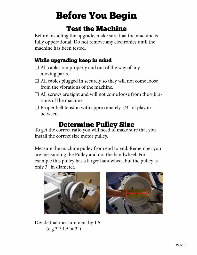
To get the correct ratio you will need to make sure that you install the correct size motor pulley.
Measure the machine pulley from end to end. Remember you are measureing the Pulley and not the handwheel. For example this pulley has a larger handwheel, but the pulley is only 3” in diameter.
Divide that measurement by 1.5 (e.g 3”/ 1.5”= 2”)
Determine Pulley Size
Before You Begin
Before installing the upgrade, make sure that the machine is fully opperational. Do not remove any electronics until the machine has been tested.
While upgrading keep in mind ☐ All cables ran properly and out of the way of any moving parts.
☐ All cables plugged in securely so they will not come loose from the vibrations of the machine.
☐ All screws are tight and will not come loose from the vibra-tions of the machine
☐ Proper belt tension with approximately 1/4” of play in between
Test the Machine

Page 4
The divided number translates to the ratio and corresponding size of pulley to be used in the upgrade. This number is likely to be a fraction, round up or down to the nearest whole number.
Use this rounded number to choose the correct pulley size. The pulley diameter should equal the rounded number.
Pulley Sizes1” 1 1/2”2” 3”
Page 5
aides
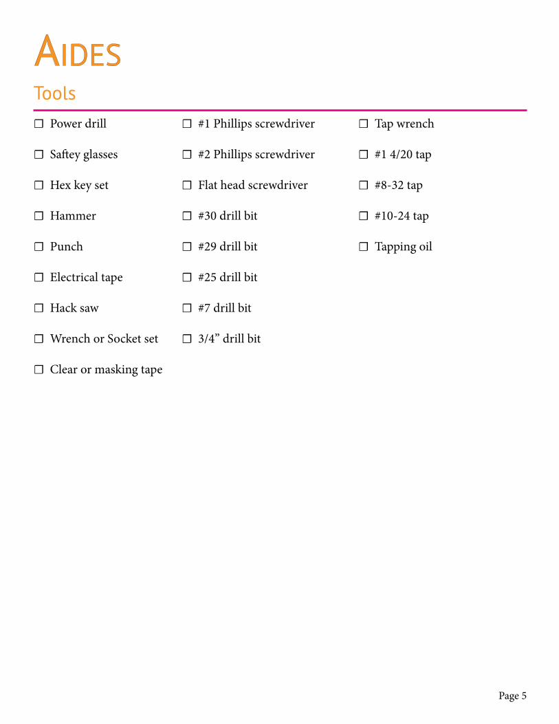
☐ Power drill
☐ Saftey glasses
☐ Hex key set
☐ Hammer
☐ Punch
☐ Electrical tape
☐ Hack saw
☐ Wrench or Socket set
☐ Clear or masking tape
☐ #1 Phillips screwdriver
☐ #2 Phillips screwdriver
☐ Flat head screwdriver
☐ #30 drill bit
☐ #29 drill bit
☐ #25 drill bit
☐ #7 drill bit
☐ 3/4” drill bit
Tools ☐ Tap wrench
☐ #1 4/20 tap
☐ #8-32 tap
☐ #10-24 tap
☐ Tapping oil

Page 6
Perfect Stitch Parts ☐ (1) Touch screen display either:
Android 10” [106AA009] Android 7” [106AA015A-7] Linux 7” [110EA164A-PS]
☐ (1) Handlebar assembly [q-e-uni-han-1-kq]
☐ Power control box [q-a-uni-pbx]
☐ (2) Remote bases [105aw025a-w]
☐ (2) Poly disc [ab146-white]
☐ (1) Index sensor with magnet [q-q-tl-oem-mag-1]
☐ (1) Rocker arm cover [112ew003-white]
☐ (1) Motor bracket [104ah003]
☐ (1) 180W drive motor [105ew57400-amp]
☐ (2) Motor heat sink [ab173]
☐ (1) Encoder kit [130aa007a]
☐ (1) Motor pulley [ab172]
☐ (4) Pan head screws [M3 x 8mm]
☐ (4) Pan head screws [#4 x 1/4”]
☐ (25) Pan head screws [#8-32 x 1/2”]
☐ (4) Hex lock nut [#8-32]
☐ (4) Pan head screws [#10-24 x 1/2”]
☐ (4) Hex lock nut [#10-24 x 1/2”]
☐ (2) Pan head screws [1/4-20 x 1/2”]
☐ (1) Rear handlebar assembly [105aw011a]
☐ (1) 110v power cable [ab178]
☐ (1) Continuous remote cable [106ew109b]
☐ (1) Continuous handlebar cable [105aw005c]

Page 7
1 - disassemble The maChine
Remove the Handlebars, Mount, and PCB box1. Loosen the knob and
remove the handlebars.
2. Unscrew the top two screws and remove the mount.
3. Unscrew the six screws attaching the PCB box face. Remove the face and set it aside.

Page 8
4. Remove the four screws on the right edge of the PCB
5. Pull the first board back to reveal the second board
6. Loosen the two screws on the right of the second board and re-move the ground wires underneath.
7. Using a hex key remove the two screws that attach tothe alluminum frame.
8. Set the screws aside and remove the PCB from the frame.

Page 9
Remove the Handwheel Cover1. Unscrew the three
screws from the belt cover. Remove the cov-er and set aside with the screws for later use.
Remove the Motor Belt1. Use a hex key to
loosen (Do not remove) the motor adjustment bolts.
2. Raise the motor bracket, remove the belt, adn then lower the motor back in place.
loosen motor adjustment bolts
Page 10
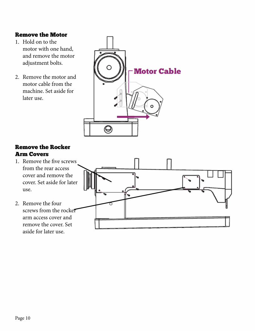
Remove the Motor1. Hold on to the
motor with one hand, and remove the motor adjustment bolts.
2. Remove the motor and motor cable from the machine. Set aside for later use.
Remove the Rocker Arm Covers1. Remove the five screws
from the rear access cover and remove the cover. Set aside for later use.
2. Remove the four screws from the rocker arm access cover and remove the cover. Set aside for later use.
Page 11
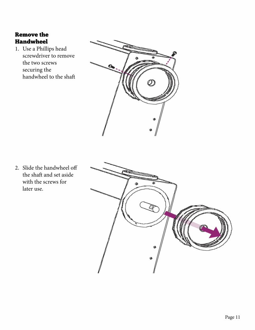
Remove the Handwheel1. Use a Phillips head
screwdriver to remove the two screws securing the handwheel to the shaft
2. Slide the handwheel off the shaft and set aside with the screws for later use.

Page 12
2 - modify The maChine
Prepare Templates1. Cut out the templates
included at the back of this manual. Cut each template along the dotted line. Read the instructions listed on the template before drilling.
Front Display 1. Tape the front display
template to the face plate of the machine.
2. Use a hammer and punch to mark the drill points.
3. Use the power drill and a #25 bit to drill the points.
4. Use a #10-24 tap on the drilled holes.

Page 13
Control Box 1. Tape the control box
template to the side of the machine. (Right from front.)
2. Use a hammer and punch to mark the drill points.
3. Use the power drill and a #29 bit to drill the points.
4. Use a #8-32 tap on the drilled holes.
5. The frame is thicker at the top right, and needs to be drilled 1/2” Mark with tape 1/2” from the tip on the bit, and drill into the frame until the tape reaches

Page 14
the frame.6. Use the #29 drill to
drill a pilot hole in the larger drill point Then drill the point with a 3/4” bit.
Rear Display 1. Tape the rear display
template to the back base of the machine.
2. Use a hammer and punch to mark the drill points.
3. Use the power drill and a #29 bit to drill the two smaller points.
4. Use a #8-32 tap on the drilled holes.
5. Use a #7 bit to drill four larger points.
6. Tap drilled holes with a #1/4-20 tap

Page 15
Rear Power Supply1. Tape the rear power
supply template to the back of the machine.
2. Use a hammer and punch to mark the drill points.
3. Use the power drill and a #29 bit to drill the four center points.
4. If there is not already a hole for the sensor, use a #29 bit to drill this point.
5. Tap the index sensor point with a #8-32 tap.

Page 16
Motor 1. Tape the motor side
template to the side of the machine. (Left from front.)
2. Use a #29 bit to drill a pilot hole through the frame.
3. Use a 3/4” bit and drill the point.

Page 17
Attach Handlebars1. Align the holes on the
handlebar bracket with the two screws facing out on the faceplate.
2. Secure the handlebars with the provided nuts.
3 - Reassemble The maChine
Page 18
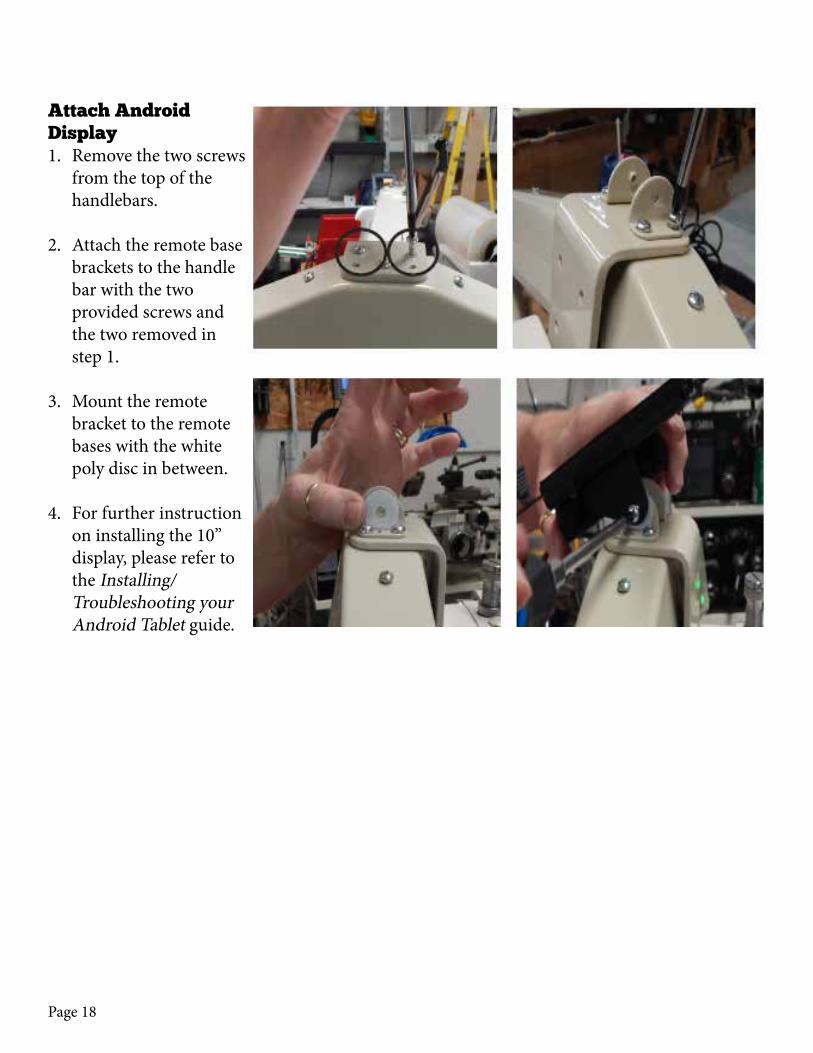
Attach Android Display1. Remove the two screws
from the top of the handlebars.
2. Attach the remote base brackets to the handle bar with the two provided screws and the two removed in step 1.
3. Mount the remote bracket to the remote bases with the white poly disc in between.
4. For further instruction on installing the 10” display, please refer to the Installing/ Troubleshooting your Android Tablet guide.

Page 19
Attach Linux Display1. Remove the two screws
from the top of the handlebars.
2. Attach the remote base brackets to the handle bar with the two provided screws and the two removed in step 1.
3. Mount the remote bracket to the remote bases with the white poly disc in between.
4. Connect the display ca-ble to the display with the side with the trian-gles facing forward.

Page 20
Feed Handlebar Wires1. Feed the three wires
coming from the handlebars through the machine to the rear.
2. Make sure the cables are out of the way of any moving components.
3. Feed the wires through the hole on the control box side.
Page 21
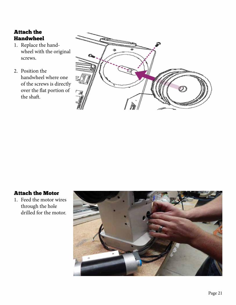
Attach the Motor1. Feed the motor wires
through the hole drilled for the motor.
Attach the Handwheel1. Replace the hand-
wheel with the original screws.
2. Position the handwheel where one of the screws is directly over the flat portion of the shaft.
Page 22
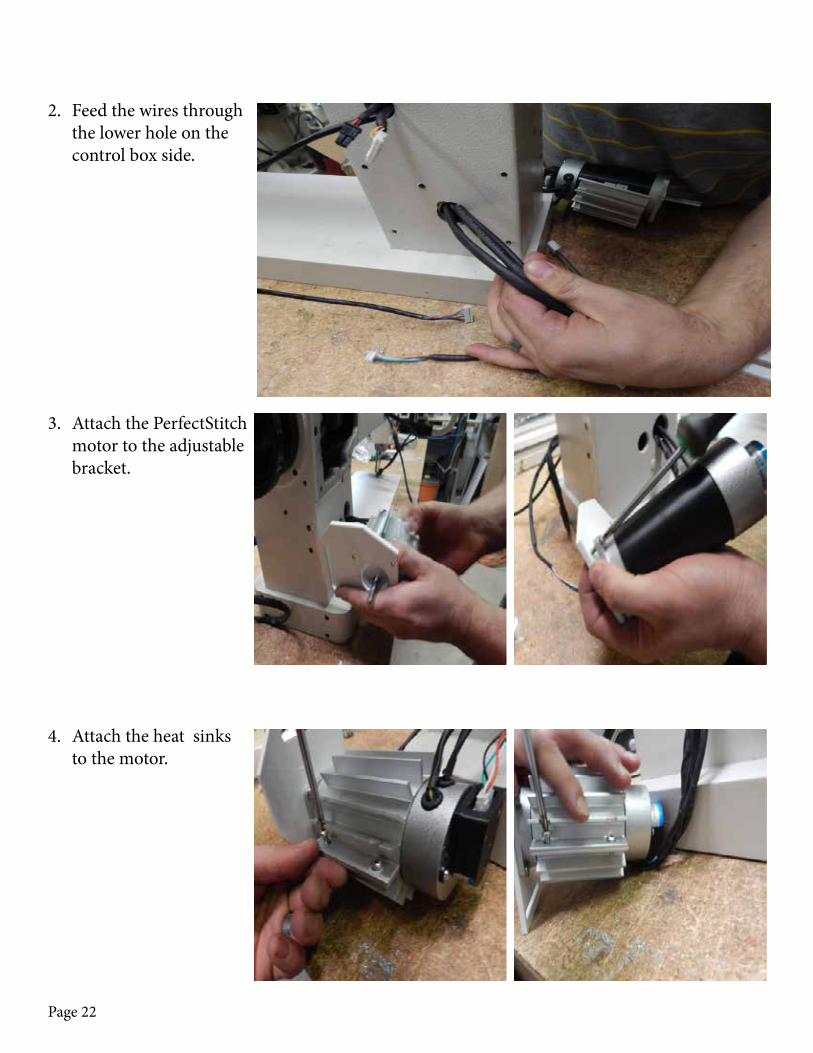
2. Feed the wires through the lower hole on the control box side.
3. Attach the PerfectStitch motor to the adjustable bracket.
4. Attach the heat sinks to the motor.

Page 23
5. Attach the adjustable bracket to the frame and secure the motor pulley.
6. Loop the belt over the pulleys.
7. Tighten down the small screw on the motor pulley with a hex key.
Page 24
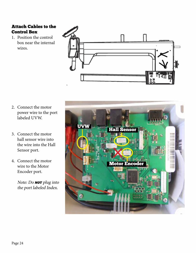
Attach Cables to the Control Box1. Position the control
box near the internal wires.
2. Connect the motor power wire to the port labeled UVW.
3. Connect the motor hall sensor wire into the wire into the Hall Sensor port.
4. Connect the motor wire to the Motor Encoder port. Note: Do not plug into the port labeled Index.
UVWHall Sensor
Motor Encoder
Page 25
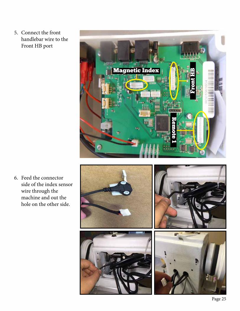
5. Connect the front handlebar wire to the Front HB port
6. Feed the connector side of the index sensor wire through the machine and out the hole on the other side.
Magnetic Index
Fro
nt
HB
Rem
ote 1
Page 26
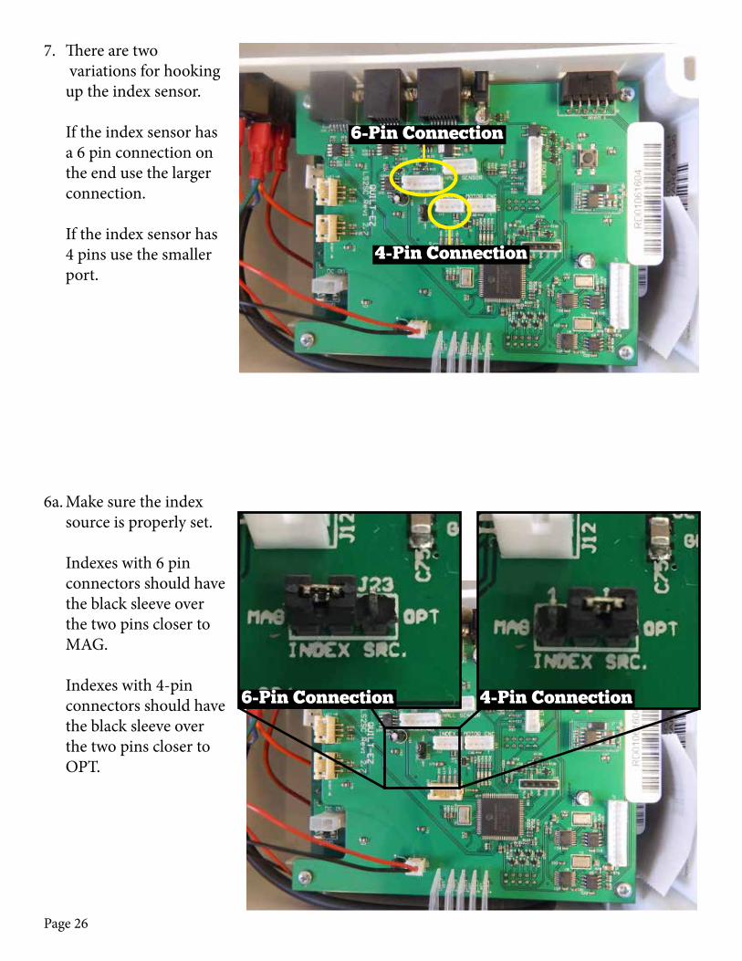
6a. Make sure the index source is properly set. Indexes with 6 pin connectors should have the black sleeve over the two pins closer to MAG. Indexes with 4-pin connectors should have the black sleeve over the two pins closer to OPT.
6-Pin Connection 4-Pin Connection
6-Pin Connection
4-Pin Connection
7. There are two variations for hooking up the index sensor. If the index sensor has a 6 pin connection on the end use the larger connection. If the index sensor has 4 pins use the smaller port.

Page 27
8. Attach the ground wire to the frame using the factory drilled hole and one of the original control box screws.
6b. If the source is not properly set, then remove the sleeve from the two pins and switch it to the appropriate side.
Page 28
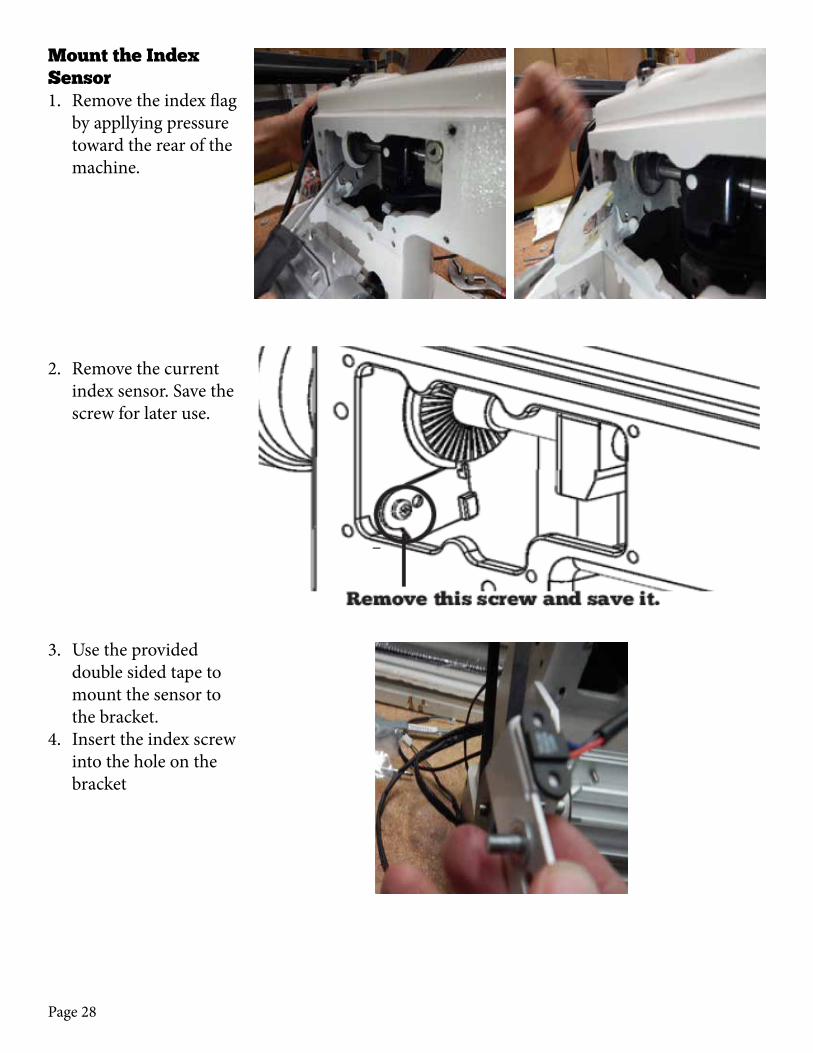
Mount the Index Sensor1. Remove the index flag
by appllying pressure toward the rear of the machine.
2. Remove the current index sensor. Save the screw for later use.
3. Use the provided double sided tape to mount the sensor to the bracket.
4. Insert the index screw into the hole on the bracket
Page 29
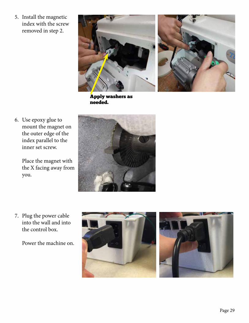
5. Install the magnetic index with the screw removed in step 2.
6. Use epoxy glue to mount the magnet on the outer edge of the index parallel to the inner set screw. Place the magnet with the X facing away from you.
7. Plug the power cable into the wall and into the control box. Power the machine on.
Apply washers as needed.

Page 30
8. Loosen the inner set screw, and spin the handwheel until the needle is top dead center. Rotate the sleeve until the magnet is directly over the index sensor, then tighten the set screw. The magnet should set about 1/4” above the sensor. There is a red light on the control box board. As the index passes over the sensor the light will illuminate. The needle should be top dead center when the light goes from on to off.
9. Power off the control box.
Set screw

Page 31
Attach the Rear Display1. Attach the rear display
to the back of the ma-chine with two 8-32 x 1/2” screws.
Attach the Control Box1. Attach the rear display
to the back of the ma-chine with two 8-32 x 1/2” screws.
Page 32
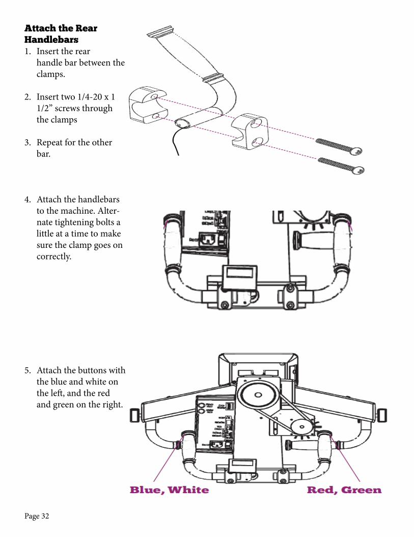
Attach the Rear Handlebars1. Insert the rear
handle bar between the clamps.
2. Insert two 1/4-20 x 1 1/2” screws through the clamps
3. Repeat for the other bar.
4. Attach the handlebars to the machine. Alter-nate tightening bolts a little at a time to make sure the clamp goes on correctly.
5. Attach the buttons with the blue and white on the left, and the red and green on the right.
Page 33
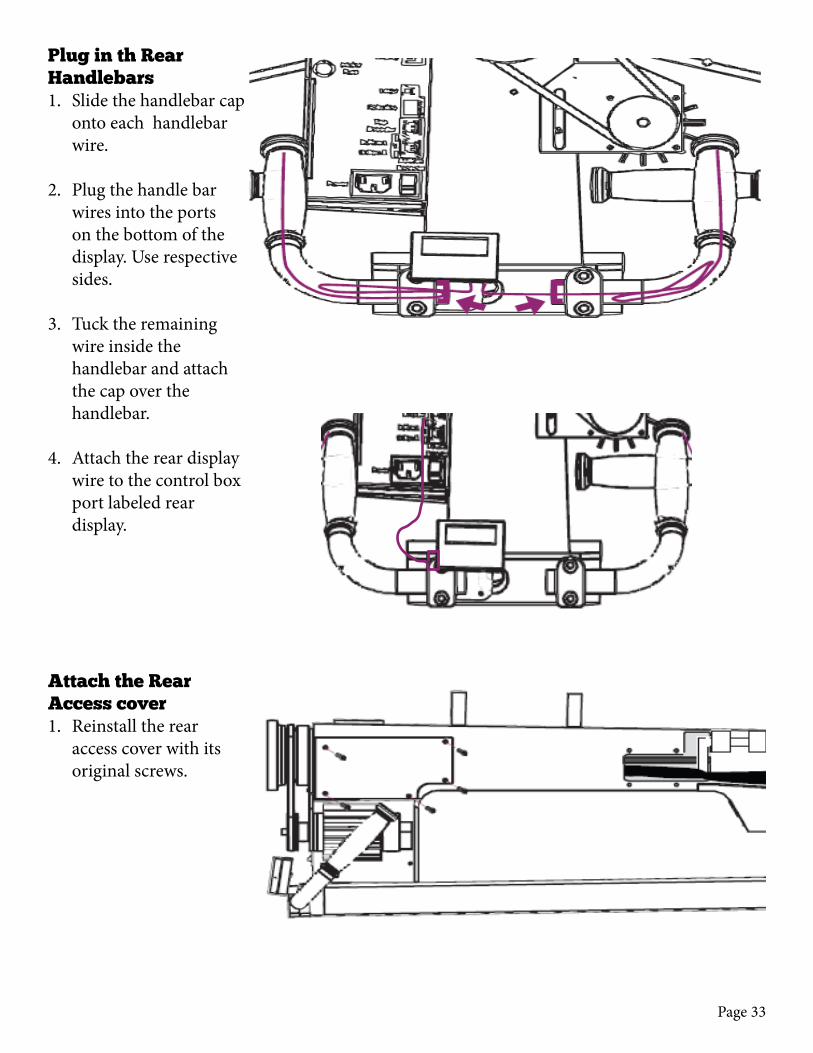
Plug in th Rear Handlebars1. Slide the handlebar cap
onto each handlebar wire.
2. Plug the handle bar wires into the ports on the bottom of the display. Use respective sides.
3. Tuck the remaining wire inside the handlebar and attach the cap over the handlebar.
4. Attach the rear display wire to the control box port labeled rear display.
Attach the Rear Access cover1. Reinstall the rear
access cover with its original screws.
Page 34
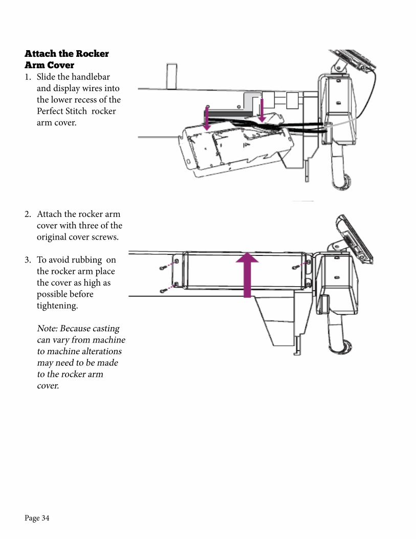
Attach the Rocker Arm Cover1. Slide the handlebar
and display wires into the lower recess of the Perfect Stitch rocker arm cover.
2. Attach the rocker arm cover with three of the original cover screws.
3. To avoid rubbing on the rocker arm place the cover as high as possible before tightening. Note: Because casting can vary from machine to machine alterations may need to be made to the rocker arm cover.
Page 35
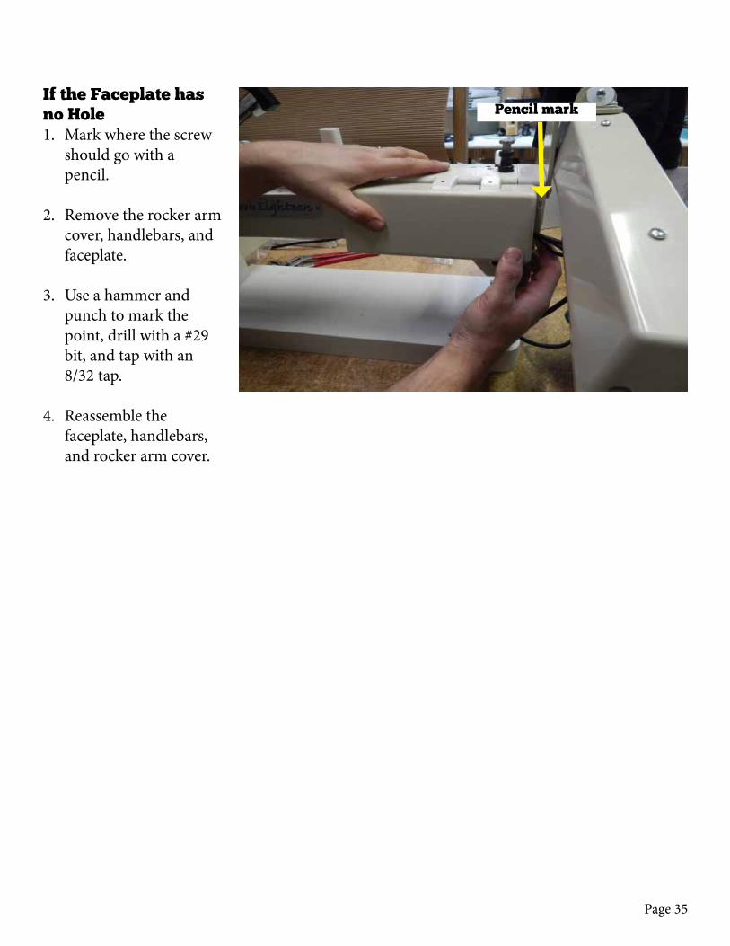
If the Faceplate has no Hole1. Mark where the screw
should go with a pencil.
2. Remove the rocker arm cover, handlebars, and faceplate.
3. Use a hammer and punch to mark the point, drill with a #29 bit, and tap with an 8/32 tap.
4. Reassemble the faceplate, handlebars, and rocker arm cover.
Pencil mark

Page 36

Page 37
To ensure the template has printed correctly, align the Handle Bar Bracket with the two (2) #25 drill bit drill holes in the above template prior to drilling.
Align the drill template horizontally with the top of the machine, with the midpoint as close to center as possible.
How high the template sits depends on customer preference. Base height on desired height for the handlebars.
Tin Lizzie 18 (Ribbon Cable) Drill Templates
Front Display Drill Template
Drill Bit Size: #25 (.1495”)Tap: #10-24
Important steps read before drilling
Front Display Drill Template
Drill Bit Size: #25 (.1495”)Tap: #10-24
==
==
==
==
==
Eã
áÇ
éç
áå
íF

Page 38
Page 39
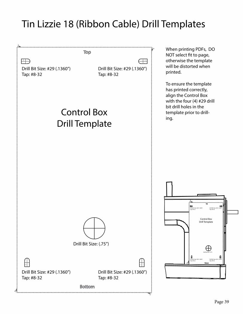
Drill Bit Size: #29 (.1360”)Tap: #8-32
Control Box Drill Template
Drill Bit Size: #29 (.1360”)Tap: #8-32
Drill Bit Size: #29 (.1360”)Tap: #8-32
Drill Bit Size: #29 (.1360”)Tap: #8-32
Drill Bit Size: (.75”)
To ensure the template has printed correctly, align the Control Box with the four (4) #29 drill bit drill holes in the template prior to drill-ing.
Tin Lizzie 18 (Ribbon Cable) Drill Templates
Drill Bit Size: #29 (.1360”)Tap: #8-32
Control Box Drill Template
Drill Bit Size: #29 (.1360”)Tap: #8-32
Drill Bit Size: #29 (.1360”)Tap: #8-32
Drill Bit Size: #29 (.1360”)Tap: #8-32
Drill Bit Size: (.75”)

Page 40

Page 41
Motor SideDrill Template
(.75”) Drill bit size
Align with
factory drilled hole
Align with
factory drilled hole
Motor SideDrill Template
(.75”) Drill bit size
Align with
factory drilled hole
Align with
factory drilled hole
Tin Lizzie 18 (Ribbon Cable) Drill Templates

Page 42
Page 43
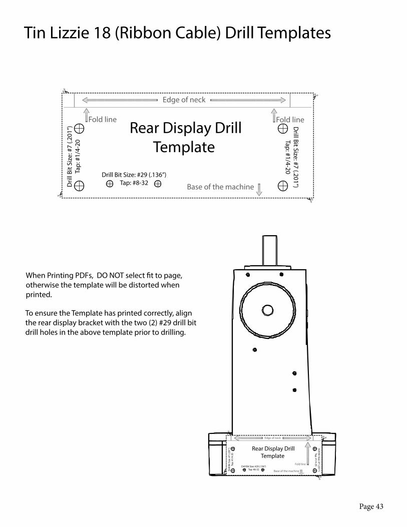
Rear Display Drill Template
Base of the machine
Drill Bit Size: #29 (.136”)Tap: #8-32D
rill B
it Si
ze: #
7 (.2
01”)
Tap:
#1/
4-20
Drill Bit Size: #7 (.201”)
Tap: #1/4-20
Edge of neck
Fold lineFold line
Tin Lizzie 18 (Ribbon Cable) Drill Templates
Rear Display Drill Template
Base of the machine
Drill Bit Size: #29 (.136”)Tap: #8-32D
rill B
it Si
ze: #
7 (.2
01”)
Tap:
#1/
4-20
Drill Bit Size: #7 (.201”)
Tap: #1/4-20
Edge of neck
Fold line
To ensure the Template has printed correctly, align the rear display bracket with the two (2) #29 drill bit drill holes in the above template prior to drilling.

Page 44
Page 45
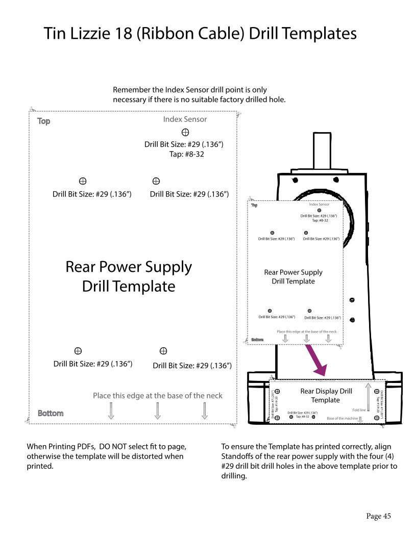
Rear Power Supply Drill Template
Place this edge at the base of the neck
Index Sensor
Drill Bit Size: #29 (.136”)
Drill Bit Size: #29 (.136”)
Drill Bit Size: #29 (.136”)
Drill Bit Size: #29 (.136”)
Drill Bit Size: #29 (.136”)Tap: #8-32
Tin Lizzie 18 (Ribbon Cable) Drill Templates
Remember the Index Sensor drill point is only necessary if there is no suitable factory drilled hole.
Rear Power Supply Drill Template
Place this edge at the base of the neck
Index Sensor
Drill Bit Size: #29 (.136”)
Drill Bit Size: #29 (.136”)
Drill Bit Size: #29 (.136”)
Drill Bit Size: #29 (.136”)
Drill Bit Size: #29 (.136”)Tap: #8-32
Rear Display Drill Template
Base of the machine
Drill Bit Size: #29 (.136”)Tap: #8-32D
rill B
it Si
ze: #
7 (.2
01”)
Tap:
#1/
4-20
Drill Bit Size: #7 (.201”)
Tap: #1/4-20Fold line

Page 46

Page 47
Still need help?
Visit support.quiltez.com for tutorial videos and additional
help documentation