Embed Size (px)
DESCRIPTION
University project. Shows how a design philosophy should be laid out before a set of calculations
Citation preview
REPORT TITLE
1 Dry dock wall
1.1 Design Philosophy
Form of construction
The dimensions of the dry dock are 50m long, 25m wide and approximately 12m deep.
Figure 1
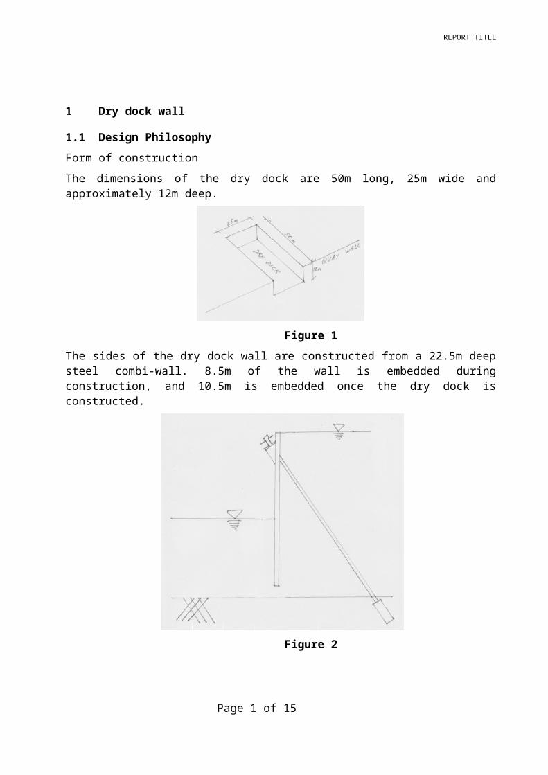
The sides of the dry dock wall are constructed from a 22.5m deep steel combi-wall. 8.5m of the wall is embedded during construction, and 10.5m is embedded once the dry dock is constructed.
Figure 2
Page 1 of 12
[Click here and type Report Title
Figure 3
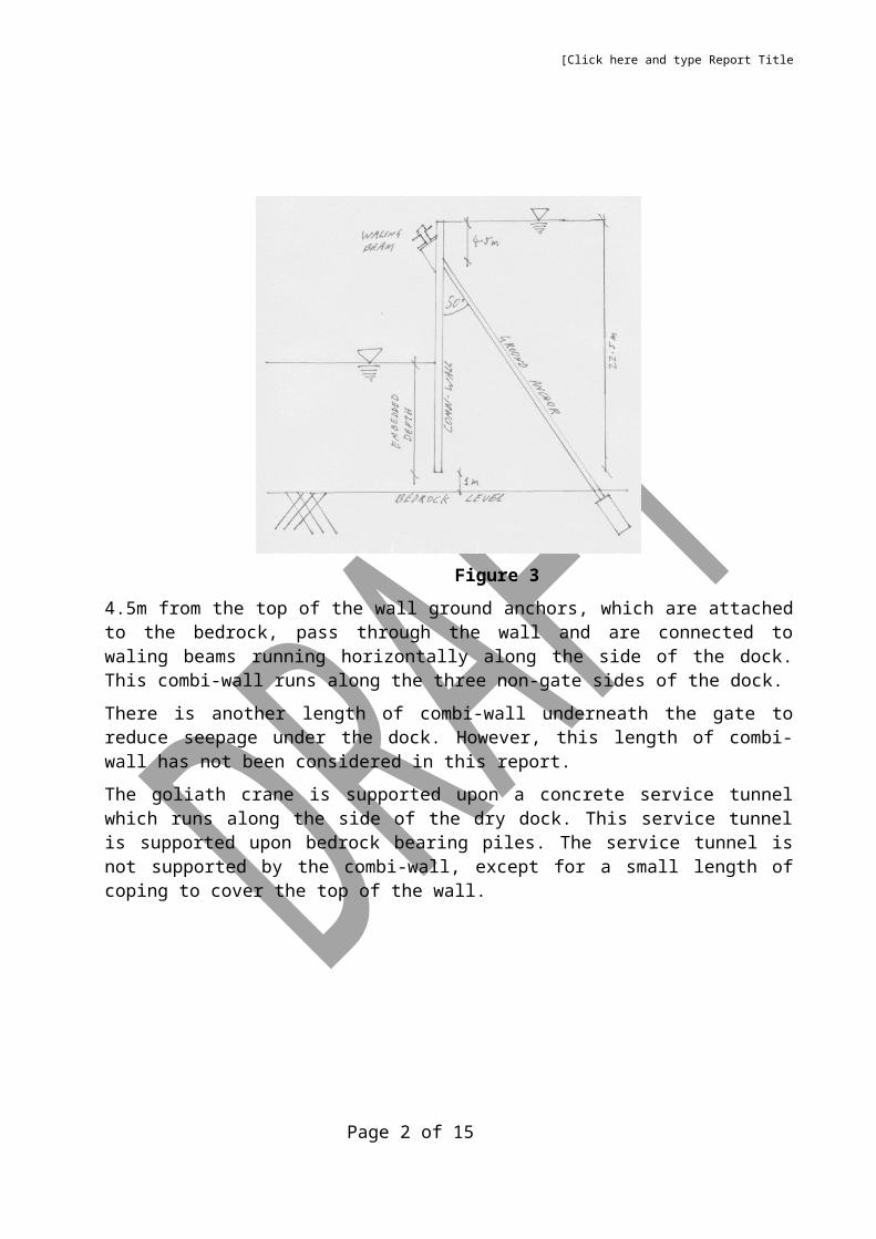
4.5m from the top of the wall ground anchors, which are attached to the bedrock, pass through the wall and are connected to waling beams running horizontally along the side of the dock. This combi-wall runs along the three non-gate sides of the dock.
There is another length of combi-wall underneath the gate to reduce seepage under the dock. However, this length of combi-wall has not been considered in this report.
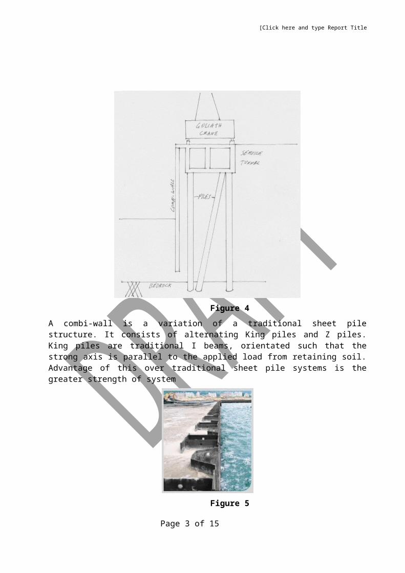
The goliath crane is supported upon a concrete service tunnel which runs along the side of the dry dock. This service tunnel is supported upon bedrock bearing piles. The service tunnel is not supported by the combi-wall, except for a small length of coping to cover the top of the wall.
Page 2 of 12
[Click here and type Report Title
Figure 4
A combi-wall is a variation of a traditional sheet pile structure. It consists of alternating King piles and Z piles. King piles are traditional I beams, orientated such that the strong axis is parallel to the applied load from retaining soil. Advantage of this over traditional sheet pile systems is the greater strength of system
Figure 5
Page 3 of 12
[Click here and type Report Title
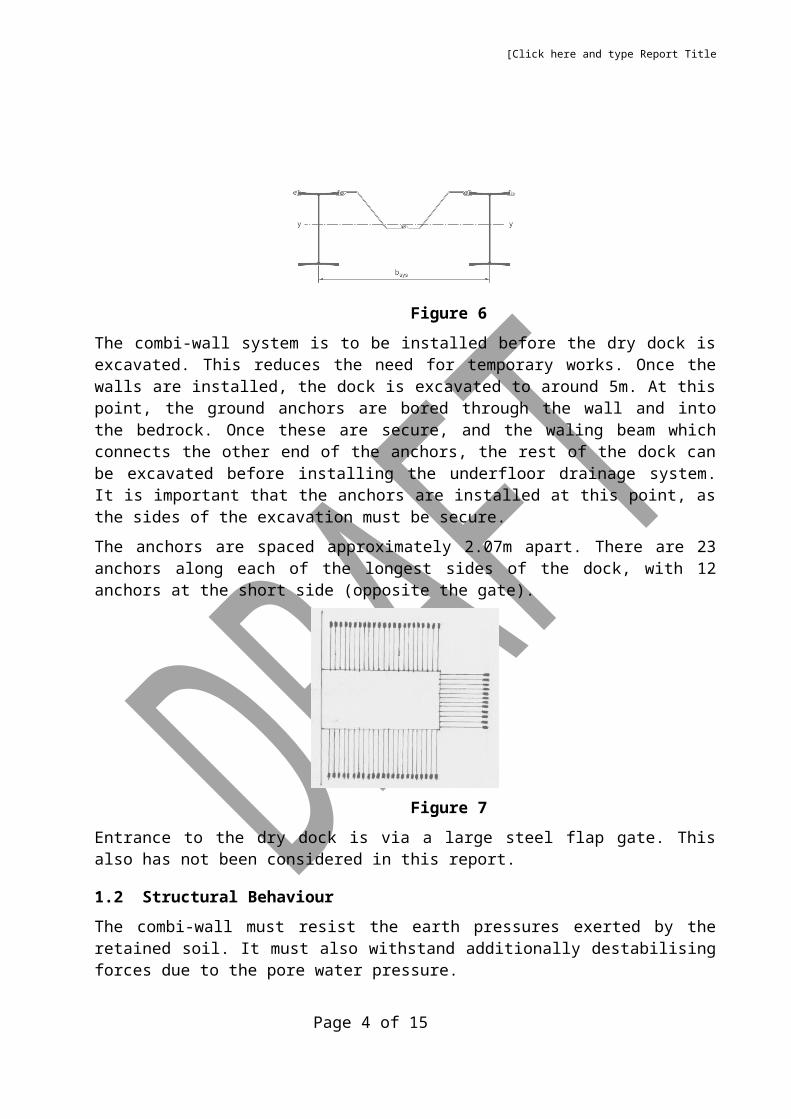
Figure 6
The combi-wall system is to be installed before the dry dock is excavated. This reduces the need for temporary works. Once the walls are installed, the dock is excavated to around 5m. At this point, the ground anchors are bored through the wall and into the bedrock. Once these are secure, and the waling beam which connects the other end of the anchors, the rest of the dock can be excavated before installing the underfloor drainage system. It is important that the anchors are installed at this point, as the sides of the excavation must be secure.
The anchors are spaced approximately 2.07m apart. There are 23 anchors along each of the longest sides of the dock, with 12 anchors at the short side (opposite the gate).
Figure 7
Entrance to the dry dock is via a large steel flap gate. This also has not been considered in this report.
1.2 Structural Behaviour
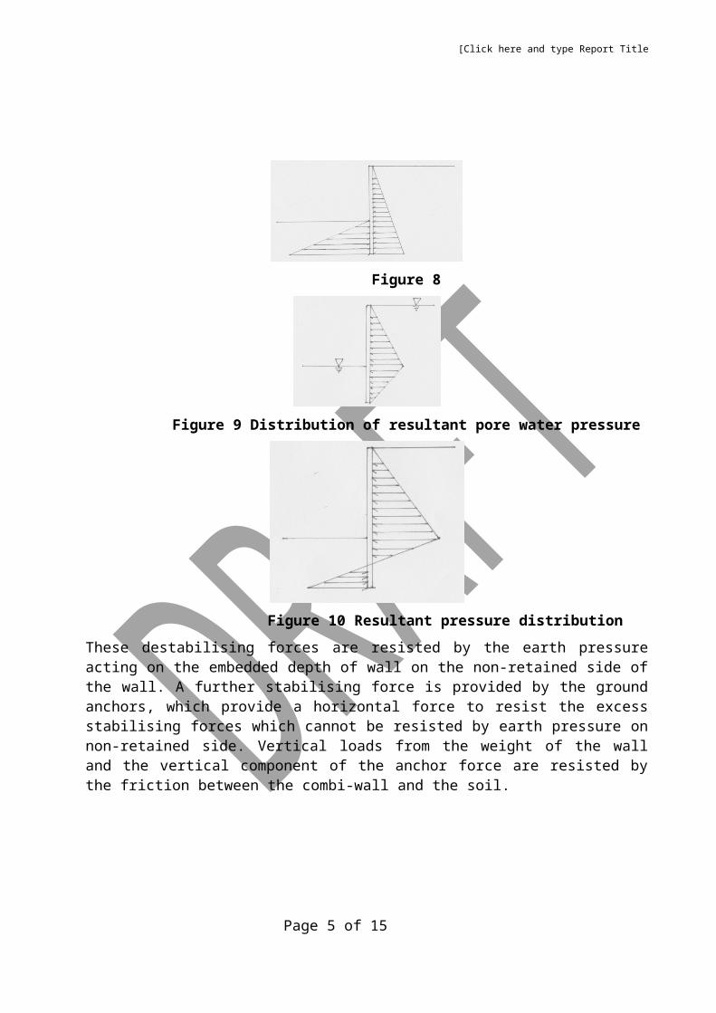
The combi-wall must resist the earth pressures exerted by the retained soil. It must also withstand additionally destabilising forces due to the pore water pressure.
Figure 8
Page 4 of 12
[Click here and type Report Title
Figure 9 Distribution of resultant pore water pressure
Figure 10 Resultant pressure distribution
These destabilising forces are resisted by the earth pressure acting on the embedded depth of wall on the non-retained side of the wall. A further stabilising force is provided by the ground anchors, which provide a horizontal force to resist the excess stabilising forces which cannot be resisted by earth pressure on non-retained side. Vertical loads from the weight of the wall and the vertical component of the anchor force are resisted by the friction between the combi-wall and the soil.
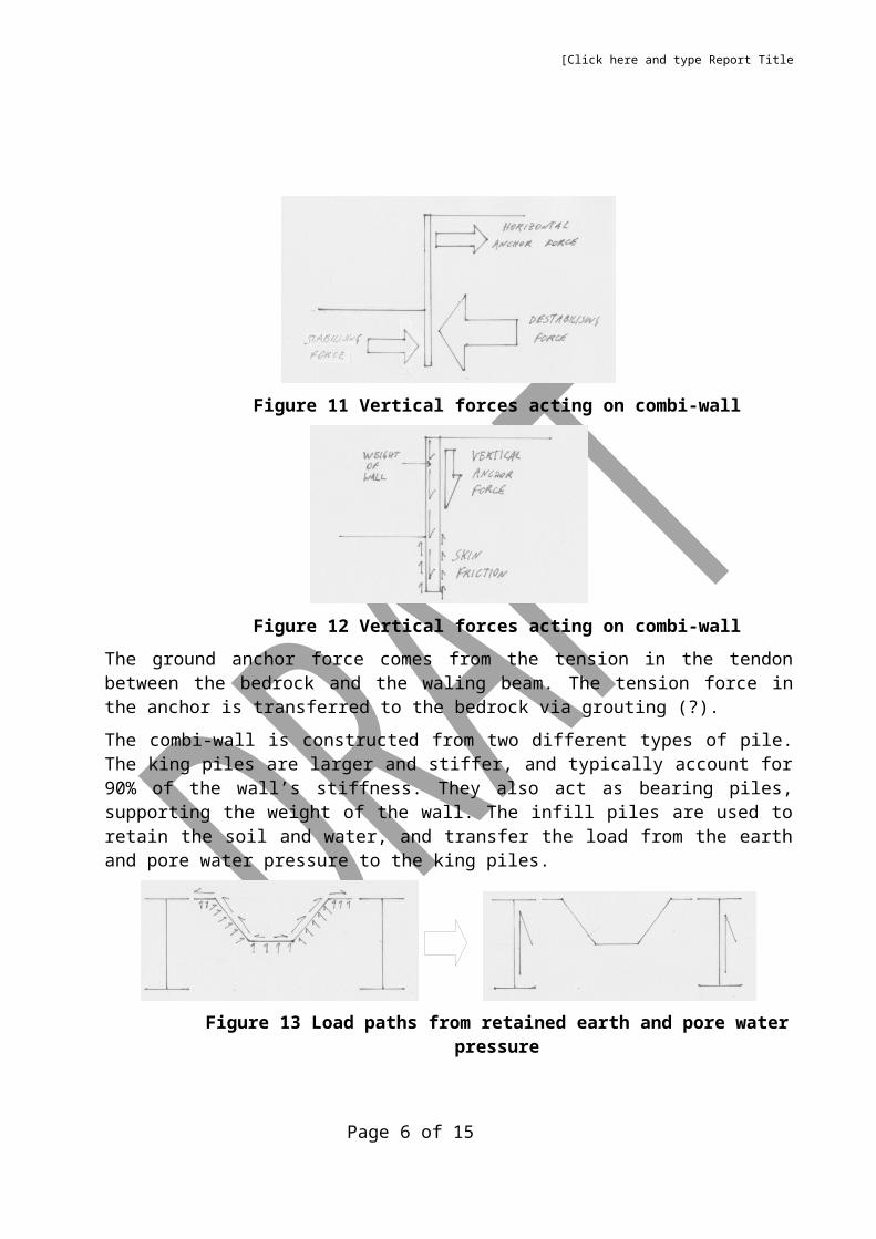
Figure 11 Vertical forces acting on combi-wall
Page 5 of 12
[Click here and type Report Title
Figure 12 Vertical forces acting on combi-wall
The ground anchor force comes from the tension in the tendon between the bedrock and the waling beam. The tension force in the anchor is transferred to the bedrock via grouting (?).
The combi-wall is constructed from two different types of pile. The king piles are larger and stiffer, and typically account for 90% of the wall’s stiffness. They also act as bearing piles, supporting the weight of the wall. The infill piles are used to retain the soil and water, and transfer the load from the earth and pore water pressure to the king piles.
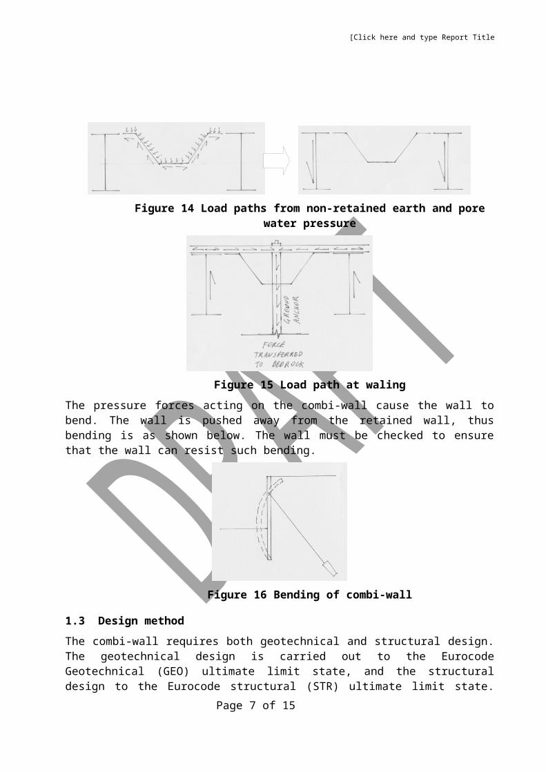
Figure 13 Load paths from retained earth and pore water pressure
Figure 14 Load paths from non-retained earth and pore water pressure
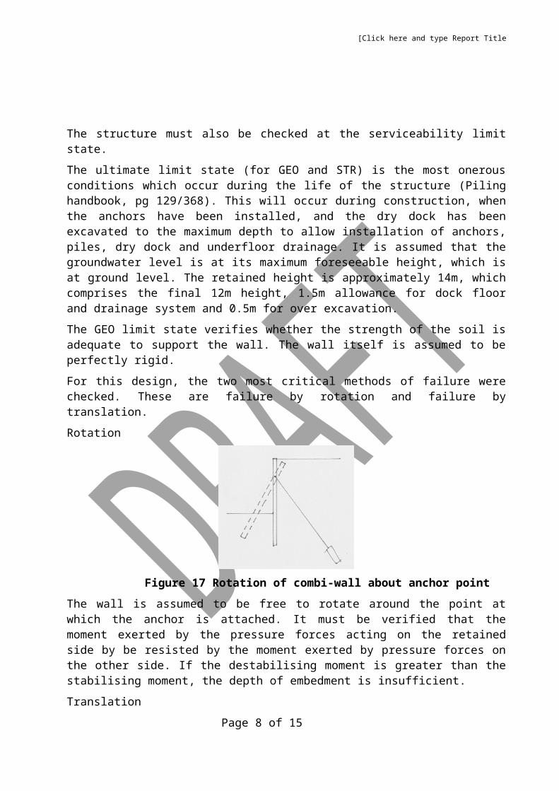
Figure 15 Load path at waling
Page 6 of 12
[Click here and type Report Title
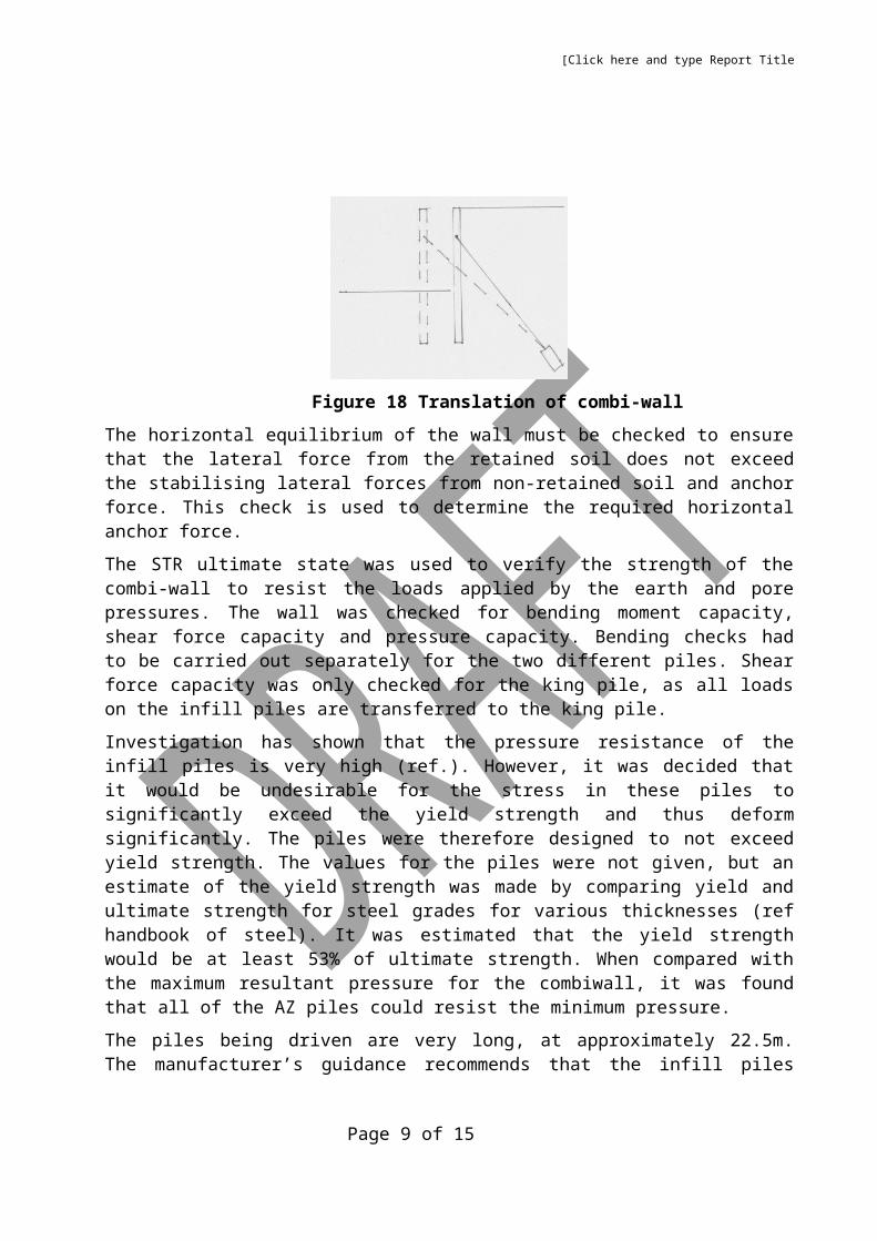
The pressure forces acting on the combi-wall cause the wall to bend. The wall is pushed away from the retained wall, thus bending is as shown below. The wall must be checked to ensure that the wall can resist such bending.
Figure 16 Bending of combi-wall
1.3 Design method
The combi-wall requires both geotechnical and structural design. The geotechnical design is carried out to the Eurocode Geotechnical (GEO) ultimate limit state, and the structural design to the Eurocode structural (STR) ultimate limit state. The structure must also be checked at the serviceability limit state.
The ultimate limit state (for GEO and STR) is the most onerous conditions which occur during the life of the structure (Piling handbook, pg 129/368). This will occur during construction, when the anchors have been installed, and the dry dock has been excavated to the maximum depth to allow installation of anchors, piles, dry dock and underfloor drainage. It is assumed that the groundwater level is at its maximum foreseeable height, which is at ground level. The retained height is approximately 14m, which comprises the final 12m height, 1.5m allowance for dock floor and drainage system and 0.5m for over excavation.
The GEO limit state verifies whether the strength of the soil is adequate to support the wall. The wall itself is assumed to be perfectly rigid.
For this design, the two most critical methods of failure were checked. These are failure by rotation and failure by translation.
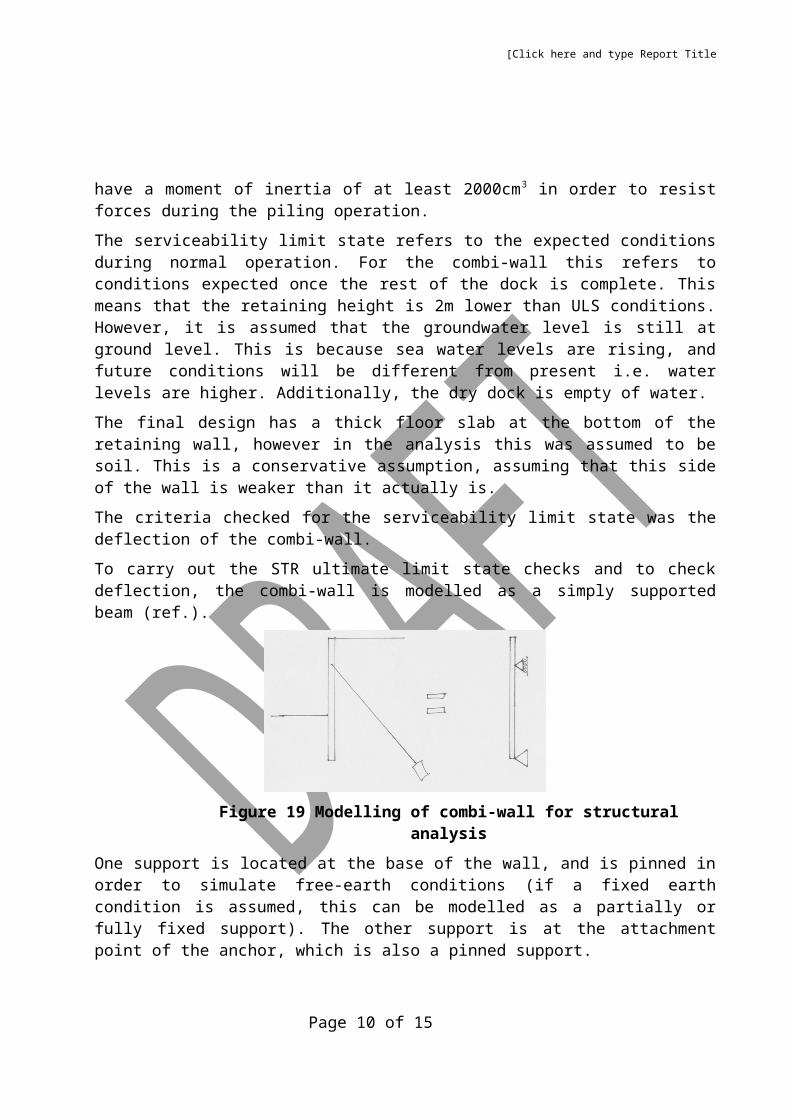
Rotation
Figure 17 Rotation of combi-wall about anchor point
Page 7 of 12
[Click here and type Report Title
The wall is assumed to be free to rotate around the point at which the anchor is attached. It must be verified that the moment exerted by the pressure forces acting on the retained side by be resisted by the moment exerted by pressure forces on the other side. If the destabilising moment is greater than the stabilising moment, the depth of embedment is insufficient.
Translation
Figure 18 Translation of combi-wall
The horizontal equilibrium of the wall must be checked to ensure that the lateral force from the retained soil does not exceed the stabilising lateral forces from non-retained soil and anchor force. This check is used to determine the required horizontal anchor force.
The STR ultimate state was used to verify the strength of the combi-wall to resist the loads applied by the earth and pore pressures. The wall was checked for bending moment capacity, shear force capacity and pressure capacity. Bending checks had to be carried out separately for the two different piles. Shear force capacity was only checked for the king pile, as all loads on the infill piles are transferred to the king pile.
Investigation has shown that the pressure resistance of the infill piles is very high (ref.). However, it was decided that it would be undesirable for the stress in these piles to significantly exceed the yield strength and thus deform significantly. The piles were therefore designed to not exceed yield strength. The values for the piles were not given, but an estimate of the yield strength was made by comparing yield and ultimate strength for steel grades for various thicknesses (ref handbook of steel). It was estimated that the yield strength would be at least 53% of ultimate strength. When compared with the maximum resultant pressure for the combiwall, it was found that all of the AZ piles could resist the minimum pressure.
The piles being driven are very long, at approximately 22.5m. The manufacturer’s guidance recommends that the infill piles have a moment of inertia of at least 2000cm3 in order to resist forces during the piling operation.
The serviceability limit state refers to the expected conditions during normal operation. For the combi-wall this refers to conditions expected once the rest of the dock is complete. This means that the retaining height is 2m lower than ULS conditions. However, it is assumed that the groundwater level is still at ground level. This is because sea water levels are rising, and future conditions will be different from present i.e. water levels are higher. Additionally, the dry dock is empty of water.
Page 8 of 12
[Click here and type Report Title
The final design has a thick floor slab at the bottom of the retaining wall, however in the analysis this was assumed to be soil. This is a conservative assumption, assuming that this side of the wall is weaker than it actually is.
The criteria checked for the serviceability limit state was the deflection of the combi-wall.
To carry out the STR ultimate limit state checks and to check deflection, the combi-wall is modelled as a simply supported beam (ref.).
Figure 19 Modelling of combi-wall for structural analysis
One support is located at the base of the wall, and is pinned in order to simulate free-earth conditions (if a fixed earth condition is assumed, this can be modelled as a partially or fully fixed support). The other support is at the attachment point of the anchor, which is also a pinned support.
The loads acting on the combi-wall for both ultimate limit states are the same.
1.4 Unit Loadings
Earth pressure
For the design of the combi-wall, an effective stress analysis was undertaken (as advised by the British maritime standards). To simplify the analysis, instead of undertaking analyses with four different soil types, only one soil type was assumed, which was alluvium. This is justified for several reasons:
The glacial till layer is very thin, therefore its effect would be minimal. As the alluvium is weaker, it is also a conservative assumption.
The pressure distribution is triangular, therefore the majority of force is generated from the deeper soil layers. The fill is stronger and the made ground is weaker, therefore any difference in results is likely to be small.
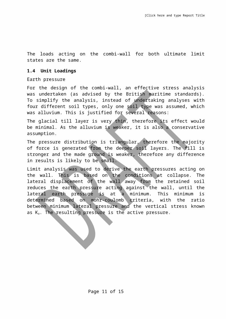
Limit analysis was used to derive the earth pressures acting on the wall. This is based on the conditions at collapse. The lateral displacement of the wall away from the retained soil reduces the earth pressure acting against the wall, until the lateral earth pressure is at a minimum. This minimum is determined based on mohr-coulomb criteria, with the ratio between minimum lateral pressure and the vertical stress known as Ka. The resulting pressure is the active pressure.
Page 9 of 12
[Click here and type Report Title
Figure 20 Active pressure
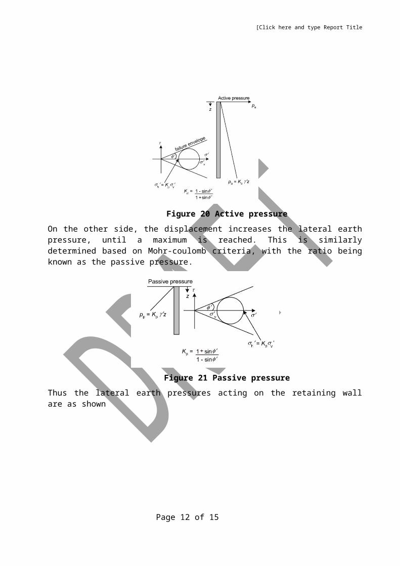
On the other side, the displacement increases the lateral earth pressure, until a maximum is reached. This is similarly determined based on Mohr-coulomb criteria, with the ratio being known as the passive pressure.
Figure 21 Passive pressure
Thus the lateral earth pressures acting on the retaining wall are as shown
Figure 22 Active and passive pressures acting on wall
For ULS analysis, the Design Approach 1b was used to derive earth pressures. This involves the use of partial factors to derive design parameters – in this case, the angle of friction.
Page 10 of 12
[Click here and type Report Title
For the serviceability checks, it is extremely complex to calculate the actual working earth pressures (ref.). Therefore an approximation is made by not factoring the design parameters (i.e. partial factors = 1) (ref. piling handbook). The resulting active and passive pressures are less onerous than under ULS conditions.
Using this method produced a problem however. As the retained height is higher in SLS conditions, the passive force increases significantly. The subsequent strand analysis indicated that the wall would deflect into the retained soil.
This clearly cannot be the case, as if the wall deflects the opposite way then the active and passive pressures would act on opposite sides. Therefore it was decided to reduce the passive force was reduced until it was approximately equal to the magnitude of the active force. This was justified as the magnitude of the passive generated cannot be larger than the resulting force pushing against it (ref. Kenny).
The resulting deflection calculated from FEM analysis showed the wall deflecting away from the retained soil. This is what was to be expected, therefore this method was considered an accurate and valid method for estimating deflection.
Parameters
Table 1 Parameter values used in ULS and SLS calculations
Parameter ULS calculations SLS calculations
φ' 43.6° 50°
Ka 0.184 0.133
Kp 5.45 7.54
A surcharge loading of 10kN/m2 was applied to the retained side of the wall to account for any loads from site traffic which may affect the stability of retained wall.
The unit weight of the soil was assumed to be 20kN/m3.
The calculation of the vertical stresses was done via an effective unit weight. As constant seepage takes place, the effective unit weight on the active side of the wall is higher than on the passive side.
Table 2 Effective unit weights used
ULS SLS
γ’-active side 14.5 kN/m2 13.6 kN/m2
γ’-passive side 5.48 kN/m2 6.36 kN/m2
The distribution of pore water pressure was assumed to be the following (Craig’s)
Page 11 of 12
[Click here and type Report Title
Figure 23 Resultant pore water pressure
The maximum pore water pressure occurs at the lower ground level, and was calculated to be:
Table 3
ULS SLS
uc 76.8 kN/m2 76.4 kN/m2
1.5 Design Standards
BS 6349 (Parts 1 through 8) – Maritime works
BS EN 1537 – Execution of special geotechnical works – Ground anchors
BS EN 12063 – Execution of special geotechnical work – Sheet pile walls
BS EN 1990 – Eurocode - Basis of structural design
BS EN 1991 – Eurocode 1: Actions of structures
BS EN 1993-1-1 – Eurocode 3: Design of steel structures – Part 1-1: General rules and rules for buildings
BS EN 1993-5 – Eurocode 3: Design of steel structures – Part 5: Piling
BS EN 1997-1 – Eurocode 7: Geotechnical design – Part 1: General rules
Above standards include UK national annexes
Page 12 of 12
uc