Embed Size (px)
Citation preview

Design Options for a Creek Crossing for a Utility CompanyDesign Options for a Creek Crossing for a Utility CompanyD gn p n f ng f U y mp nyE i i B id d i C di iProject Description Existing Bridge and Site Condition Scope of Work & DeliverablesProject Description
In order to access its critical communication g g
80 ft Modular BridgeScope of Work & Deliverables• Written Proposal (submitted in Dec ‘11)In order to access its critical communication
t l t d ithi ti l k tilit 80-ft Modular Bridge • Written Proposal (submitted in Dec 11)
Tasks deliverables and milestonestowers located within a national park, a utility l f b d
◦Tasks, deliverables and milestonesS h d l d b d t company currently uses a prefabricated, ◦Schedule and budget p y y p
modular steel bridge that is supported on • Final Design Report (submitted in June ‘12)g pptemporary timber supports. The utility company
g p◦Design drawings & calculation packagetemporary timber supports. The utility company
requested the senior design team to carry out g g p g
◦Preliminary construction sequencerequested the senior design team to carry out structural designs for two alternative
Preliminary construction sequence◦Design specifications for materials and structural designs for two alternative
t k i◦Design specifications for materials and procedurespermanent creek crossings. proceduresC t ti t ti t◦Construction cost estimates
T f ti◦Recommended preferred alternative
Temporary footingsp
Option 1: Design Permanent Abutments for Existing Bridge Option 2: Vented Ford DesignOption 1: Design Permanent Abutments for Existing Bridge Option 2: Vented Ford DesignD i F tDesign Features Design Features
Trash Rackg• Existing modular steel bridge can be • 3-culvert structure replaces existing Trash Rack
Abutments Existing modular steel bridge can be re-used on proposed reinforced
p gsteel bridge.Removable
Abutmentsre-used on proposed reinforced concrete abutments
steel br dge.• Components include reinforced
PanelsCulvert concrete abutments.
P d i l ti (30 Components include reinforced
concrete precast road panels culvert wallsFlow
• Proposed new crossing location (30 f ) h f
concrete precast road panels, culvert walls bottom slab and steel trash rack
Direction
feet upstream) is narrower; therefore walls, bottom slab and steel trash rack. R d l bl t id
pbridge span need not be increased. • Road panels are removable to provide g p• New location provides more free access for debris cleanup.
Existing New location provides more free board thus reducing the potential of
p• Steel trash rack upstream facilitates Flow Direction
Existing temporary board thus reducing the potential of
bridge damage during major runoff Steel trash rack upstream fac l tates
debris to overtop the structuretemporary foundations bridge damage during major runoff
tdebris to overtop the structure.
events. E b d d • Existing bridge can provide access to g g p
communication towers during gconstruction of permanent abutments.construction of permanent abutments.
Cross Sectional View of Vented FordPlan View of Abutment Sectional View of Abutment Cross-Sectional View of Vented FordPlan View of Abutment Sectional View of Abutment
Knowledge and Skills GainedMultidisciplinary Features C t E tim t nd C t Fill Knowledge and Skills GainedT h i l Skill
Multidisciplinary FeaturesH d l l
Cost Estimates and Cut-Fill •Technical Skills
k k l d f 01 l B ld d •Hydraulic Analysis Quantities ◦Working knowledge of 2012 International Building Code,
y y◦carried out preliminary analysis to
Quantities g g g2010 AASHTO LRFD Bridge Design Specification, Naval
p y ydetermine depth of flow and free board of Option1 Option 2 g g p ,
Facilities Foundation Design Manual County Codes Drafting determine depth of flow and free board of crossing
Option1 Option 2 Facilities Foundation Design Manual, County Codes, Drafting Standards AutoCAD 2010 and Construction Specifications
crossing•Geotechnical Analysis Cost $120,000 $114,000 Standards, AutoCAD 2010, and Construction Specifications
◦Cost Estimation using RSMeans and Sponsor’s unit costs•Geotechnical Analysis
i d t t bilit l i f b k l $ , $ ,
Cut 2200 cu yd 1180 cu yd ◦Cost Estimation using RSMeans and Sponsor s unit costs.C i ti Skill
◦carried out stability analysis of bank slopes & b ll b f l
Cut 2200 cu. yd 1180 cu. yd•Communication Skills
l l f l f & abutment walls, bearing capacity of soils Fill 1470 cu. yd 290 cu. yd
◦Oral presentations to class, to professional engineers from p y
•Site Development C t E ti t E l d l b t
y yp p g
department advisory board, to sponsoring company and at p
◦carried out cut and fill analysis and •Cost Estimate Excludes labor costs. 1 l d h f h
p y , p g p ylocal professional society meetings.
carried out cut and fill analysis and regrading Option 1 includes the cost of the local professional society meetings.
◦Developed technical writing skills through proposal final regrading
•Environmental Issuesp
prefabricated steel bridge ◦Developed technical writing skills through proposal, final report technical memos and emails
•Environmental Issuesid d b di f ildlif t
p greport, technical memos and emails.W k d l l ith f i l i j t
◦considered breeding season of wildlife to d f d R d d O ti ◦ Worked closely with professional engineers, a project
f h l d h l define an optimum construction window Recommended Option
manager from the utility company, and a technical writerp
◦mimimum impact on natural environmentp
◦ Vented Ford Crossing preferred g y p y• Project Management and Leadership skills
p• Permit Requirements
Vented Ford Crossing preferred due to lower cost easy j g p
◦Prepared agenda and managed meetings followed up on action Permit Requirements◦researched Federal State county and city
due to lower cost, easy maintenance better ability to Prepared agenda and managed meetings, followed up on action
items; managed schedules and budgets; worked as a team◦researched Federal, State, county and city permits applicable to the project
maintenance, better ability to ith t d d b i fl items; managed schedules and budgets; worked as a team.permits applicable to the project. withstand debris flow.

Design Options for a Creek Crossing for a Utility Company Abstract
All engineering students in our department are required to complete a team-based, nine month long, real life senior design project. A utility company approached our department requesting that one of our capstone teams design a crossing for a creek. The crossing allowed maintenance crew access to communication towers managed by the utility company. Currently a modular steel bridge placed on concrete blocks serves as a temporary crossing. The company wanted the team to provide them with two crossing options: the first option had to reuse the modular bridge placed on permanent supports and the second option had to be an entirely new crossing design. Furthermore, the team was asked to recommend a preferred option. A team of four students worked under the supervision of a licensed Professional Engineer and a Project Manager from the utility company and a faculty advisor who is also a licensed civil engineer to develop the design options. In fall quarter, the team prepared a written proposal to the utility company outlining the scope of work, list of tasks, deliverable, schedule and budget. The team spent the winter and spring quarters carrying out the structural design of the crossings. The first option for the crossing consisted of moving the existing modular bridge 30 feet upstream to higher ground where the creek width is narrower than its current location. Preliminary slope stability analysis showed that the relocation minimized bank instability issues. In addition, the existing modular bridge could provide access to towers during construction of the new crossing. The team designed the abutments and the wing walls for the modular bridge. The second option involved a vented ford crossing which is a concrete culvert with three openings and a trash rack at the upstream end to clear the debris over the structure. The ford crossing was designed such that in the event of a storm event involving large debris, the structural members could be disassembled, the system cleaned up and the crossing reassembled. The team prepared a final report describing the design options and the preferred alternative including the AutoCAD drawings, construction cost estimates and design calculations for both options. In addition to the structural and geotechnical analyses, the team was exposed to other aspects of the project. The team performed a preliminary hydraulic analysis to ensure the new designs could handle the anticipated floods. The crossing was located in a national park and the team had to consider the relevant federal, state, county and city permits. The site was a breeding ground for Marbled Murrelet and Spotted Owl. Therefore the team had to take the breeding period into account when recommending a construction window to the utility company. Throughout the academic year, the team had separate weekly meetings with the faculty advisor and the company liaison. Each team member served as the project manager during the year, running meetings, setting agendas, assigning tasks to members and following up on action items. The team made multiple presentations to the class, the utility company, the departmental advisory board and at professional society meetings. The project strengthened the team’s ability to apply their technical knowledge to a practical problem, to work as a team, to communicate effectively, to develop and hone professional and leadership skills and to meet the client’s needs.

DESIGN OPTIONS FOR A CREEK CROSSING FOR A UTILITY COMPANY
I. Project Description Introduction A local utility company requested one of our capstone design teams to provide two alternative engineering design approaches to cross a creek. The crossing was needed to allow maintenance crews access to the communication towers managed by the utility company. The towers provide services to local power utilities, as well as to cellular and radio communication, dam control and state patrol. Over the past 30 years the utility company (hereafter referred to as Company) has implemented several temporary crossings that have failed due to seasonal floods. The most recent temporary solution was built in 2010 and consists of an 80-foot modular steel bridge placed on timber footings as shown in Figure 1. However, there is concern that the footings are supported on backfilled slopes vulnerable to erosion during heavy floods. The Company had considered either lengthening the existing modular bridge and providing permanent abutments for support or replacing the bridge with a different permanent crossing system. The Company approached our university to carry out the designs for the two options as part of our senior capstone program.
Figure 1. Modular Bridge on Temporary Timber Support Background The creek is typically 25 ft wide but is subject to heavy seasonal flow that can make it much wider. In addition, the 13% slope of the creek bed results in heavy debris flow which has compromised the integrity of the crossing in the past. In 1980 a gravel bedded ford was placed across the creek, as shown in Figure 2a, but was washed off by floods. Subsequently a concrete slab was placed across the creek but in mid 1990’s the Company decided to revert back to the gravel bedded ford. In 2006, a three-culvert crossing was installed as shown in Figure 2b. However, improper placement and grading of gravel
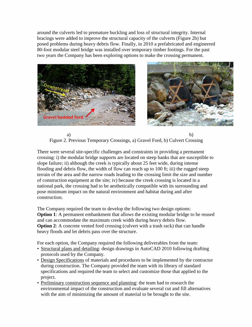
around the culverts led to premature buckling and loss of structural integrity. Internal bracings were added to improve the structural capacity of the culverts (Figure 2b) but posed problems during heavy debris flow. Finally, in 2010 a prefabricated and engineered 80-foot modular steel bridge was installed over temporary timber footings. For the past two years the Company has been exploring options to make the crossing permanent.
a) b)
Figure 2. Previous Temporary Crossings, a) Gravel Ford, b) Culvert Crossing There were several site-specific challenges and constraints in providing a permanent crossing: i) the modular bridge supports are located on steep banks that are susceptible to slope failure; ii) although the creek is typically about 25 feet wide, during intense flooding and debris flow, the width of flow can reach up to 100 ft; iii) the rugged steep terrain of the area and the narrow roads leading to the crossing limit the size and number of construction equipment at the site; iv) because the creek crossing is located in a national park, the crossing had to be aesthetically compatible with its surrounding and pose minimum impact on the natural environment and habitat during and after construction. The Company required the team to develop the following two design options: Option 1: A permanent embankment that allows the existing modular bridge to be reused and can accommodate the maximum creek width during heavy debris flow. Option 2: A concrete vented ford crossing (culvert with a trash rack) that can handle heavy floods and let debris pass over the structure. For each option, the Company required the following deliverables from the team: • Structural plans and detailing: design drawings in AutoCAD 2010 following drafting
protocols used by the Company. • Design Specifications of materials and procedures to be implemented by the contractor
during construction. The Company provided the team with its library of standard specifications and required the team to select and customize those that applied to the project.
• Preliminary construction sequence and planning: the team had to research the environmental impact of the construction and evaluate several cut and fill alternatives with the aim of minimizing the amount of material to be brought to the site.
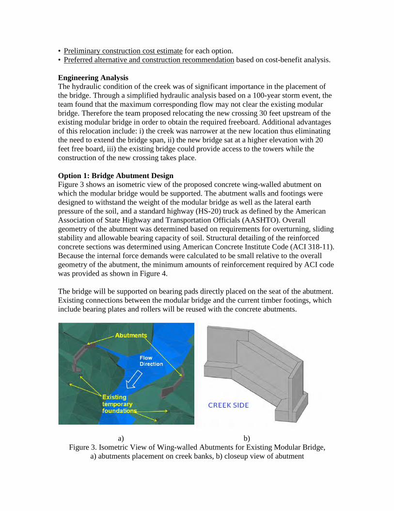
• Preliminary construction cost estimate for each option. • Preferred alternative and construction recommendation based on cost-benefit analysis. Engineering Analysis The hydraulic condition of the creek was of significant importance in the placement of the bridge. Through a simplified hydraulic analysis based on a 100-year storm event, the team found that the maximum corresponding flow may not clear the existing modular bridge. Therefore the team proposed relocating the new crossing 30 feet upstream of the existing modular bridge in order to obtain the required freeboard. Additional advantages of this relocation include: i) the creek was narrower at the new location thus eliminating the need to extend the bridge span, ii) the new bridge sat at a higher elevation with 20 feet free board, iii) the existing bridge could provide access to the towers while the construction of the new crossing takes place. Option 1: Bridge Abutment Design Figure 3 shows an isometric view of the proposed concrete wing-walled abutment on which the modular bridge would be supported. The abutment walls and footings were designed to withstand the weight of the modular bridge as well as the lateral earth pressure of the soil, and a standard highway (HS-20) truck as defined by the American Association of State Highway and Transportation Officials (AASHTO). Overall geometry of the abutment was determined based on requirements for overturning, sliding stability and allowable bearing capacity of soil. Structural detailing of the reinforced concrete sections was determined using American Concrete Institute Code (ACI 318-11). Because the internal force demands were calculated to be small relative to the overall geometry of the abutment, the minimum amounts of reinforcement required by ACI code was provided as shown in Figure 4. The bridge will be supported on bearing pads directly placed on the seat of the abutment. Existing connections between the modular bridge and the current timber footings, which include bearing plates and rollers will be reused with the concrete abutments.
a) b) Figure 3. Isometric View of Wing-walled Abutments for Existing Modular Bridge,
a) abutments placement on creek banks, b) closeup view of abutment

Figure 4 Wing-walled Abutment, a) Plan view b) Sectional view Option 2: Vented Ford Design The vented ford structure presented in Figure 5 is an alternative to the existing modular bridge. The structure consists of three concrete culverts and a trash rack on the upstream end which is intended to allow the debris to overtop the structure.
Flow Direction
Trash Rack
Removable PanelsCulvert
walls
Figure 5. Vented Ford Crossing The design of the vented ford was much more elaborate than that of option 1. Key components of the structure are shown in Figure 6 and include removable precast concrete panels at the superstructure, cast-in-place culvert walls and, concrete bottom slab that is keyed to the bed of the creek. A trash rack system made of steel wide flange beams was proposed on the upstream side of the structure (Figure 5) to facilitate the flow of debris over the ford. Road panels were designed as removable members to allow access for clearing out any debris stuck within the culvert walls. The trash rack system was therefore not supported on the panels but was designed as an edge beam spanning between culvert walls. The team was responsible for designing member sizes, reinforcement, and construction details for all reinforced concrete members (road panels, culvert walls, and bottom slab) and the steel trash rack system.

Figure 6. Cross Sectional View of Vented Ford
Earthwork Calculations The design team computed cut-and-fill volumes for both options. Slope requirement for access roads set forth in AASHTO (2010) resulted in significant amount of re-grading. For the selected crossing location, the modular bridge abutment option required 2190 cu. yards of excavation and 1470 cu. yards of fill. Conversely, the vented ford option required 1180 cu.yards of excavation and 290 cu.yards of backfill. The difference in earthwork volume between the two options was because the roadway elevation of the vented ford was about 5 feet below that of the modular bridge roadway. The team recommended that selected cut material be used as backfill. II. Collaboration of Faculty, Students and Licensed Professional Engineers Students in our engineering program are required to complete a year-long, industrially sponsored, real life capstone project. A diverse group of four students worked on this project under the supervision of a liaison engineer from the sponsoring agency and a structural engineering faculty member from the university, both licensed professional engineers. In addition, the senior design course is taught by a faculty member who is also a licensed professional engineer and served as a geotechnical engineering consultant to the team. The students met weekly with the faculty advisor and with their sponsor liaison. The faculty members and the liaison provided feedback on the proposal and report throughout the academic year. Our department has an active advisory board consisting of about a dozen licensed, local civil engineering practitioners that meets quarterly to provide feedback on curriculum, future growth and other industry-academic issues. The team made an oral presentation to the board in early winter quarter describing their project scope and plan of action. Two of the advisory board members provided critical feedback on the final drafts of the proposal
and report. The students were required to address their comments when finalizing these documents. In fall and spring quarters the team presented their work to the Company. Diverse groups of professionals attended these presentations. The students found these presentations to be quite challenging due to the extensive knowledge and experience of the audience and the questions asked. But they agreed that it was a great career growth experience. Our department hired a professional technical writer during the fall quarter to help the team with the proposal preparation. The technical writer worked closely, meeting with the team frequently and providing critical feedback on several drafts of their proposal. This resulted in a high quality deliverable to the Company. III. Benefit to Public, Health, Safety and Welfare The safety of the maintenance crew was of utmost importance throughout the design process. At the end of the academic year the students had the opportunity to participate in the Order of the Engineer “ring” ceremony which reinforces the obligation and professional responsibility of the Engineer and the ASCE Code of Ethics. IV. Multidiscipline and/or Allied Profession Participation Though the team focused primarily on the structural design, they had to also take into account other project issues. Taking into account that the project site was located within a national park, the team researched the applicable federal, state, county and city permits and provided them to the client. The project site is a breeding area for Marbled Murrelet and Spotted Owl. Therefore the team met with the environmental group within the Company to discuss the environmental issues and researched the breeding periods of the wild life. The team weighed the two constraints of avoiding the breeding periods of the wildlife and constructing the earthwork during low (to no) flow period and recommended a construction window of July 15th to September 15th. The team also carried out a preliminary hydraulic analysis to determine the placement of the bridge deck with the appropriate freeboard. V. Knowledge and Skills Gained The project enabled the students to develop the following: technical skills, oral and written communication skills, project management and leadership skills, ability to work in a team setting and to interact with clients. a) Technical skills The students learned how to take a project from brainstorming stage to final design. During this project they acquired the skill to use the following tools: • Design Manuals: 2012 International Building Code, 2010 AASHTO LRFD Bridge
Design Specifications, Naval Facilities Design Manual for Foundations and Earth Structures.
• County design codes and drafting standards • Software: SAP2000 for the determination of internal force demands.
• Computer aided drafting (AutoCAD 2010) The Company conducted training sessions on their standard drafting practices, so that the deliverables met Company standards.
• Standard Specification of Materials and Construction Procedures Students have had limited exposure to these design manuals, codes and software in their classes. But they had the opportunity to work with them intensively on the project with the help of the faculty advisor and the liaison engineer. b) Communication skills The students submitted a written proposal to the sponsor at the end of fall quarter, outlining their understanding of the project, scope of work, plan of implementation, and schedule. At the end of spring quarter, they submitted a final report describing the work done, engineering drawing, calculation and other deliverables requested by the sponsor. The students were required to make formal oral presentations to their peers twice a quarter. Every student was required to make at least one presentation each quarter. In addition, students presented their proposed work to the Company sponsors at the end of fall quarter. They presented their final design to the Company at the end of spring quarter. The academic year concluded with a major event on campus where the team presented its work to the entire university community, sponsors of all the various senior capstone projects, prospective sponsors, friends, family and alumni through oral presentations and a poster session. c) Project Management and Leadership skills The student team met with the faculty advisor and the liaison each week. Each team member served as the project manager for part of the academic year. The project manager was responsible for setting up the team meetings, developing the meeting agenda, conducting the meetings, assigning tasks and following up on action items. He/She was also responsible for contacting the liaison and the faculty advisor in between team meetings, when needed. The team provided formative feedback through the course instructor to the project manager. Summary A team of four civil engineering seniors designed two alternative permanent creek crossings that would serve as a maintenance access road to transmission towers operated by a utility Company. The project was completed under the supervision of a liaison engineer from the Company and two faculty members all licensed professional engineers. They were also aided by a Project Manager from the Company. One of the options consisted of extending the length of the currently existing modular bridge and placing it on permanent abutments. The second option was a vented ford, namely a concrete culvert with a trash track capable of handling heavy flows and blocking large debris. Through this project the team learned how to apply the technical skills learned in structural and geotechnical engineering courses to a real life project. Moreover, the students developed project management, leadership and communication skills, and client relationships with licensed professional engineers. The students were exposed to various design codes and software, and environmental, construction and permitting issues.