Embed Size (px)
Citation preview
Design Optimization and Performance of Pumping Options for VTR Extended Length Test Assembly for Lead Coolant (ELTA-LC), June 2020.
Technical Report Number: UNM-ISNPS-1-2020
1
Design Optimization and Performance
of Pumping Options for VTR Extended
Length Test Assembly for Lead Coolant
(ELTA-CL)
Mohamed S. El-Genk, Timothy Schriener, Andrew Hahn
and Ragai Altamini Institute for Space and Nuclear Power Studies and Nuclear Engineering
Department, University of New Mexico, Albuquerque, NM, 87131
Technical Report Number: UNM-ISNPS-1-2020 Performance Period: December 2019 – June 2020
Work funded by Battelle Energy Alliance, LLC,
Award No. 145662 to the University of New Mexico.
June 2020
Design Optimization and Performance of Pumping Options for VTR Extended Length Test Assembly for Lead Coolant (ELTA-LC), June 2020.
Technical Report Number: UNM-ISNPS-1-2020
2
1. Executive Summary
The Versatile Test Reactor (VTR) project established an experimental program that aims to
develop fully instrumented Extended Length Test Assembly for Lead Coolant (ELTA-CL),
which will contain a coolant system segregated from the reactor/primary sodium coolant. The
University of New Mexico’s Institute for Space and Nuclear Power studies (UNM-ISNPS) has
been tasked with conducting feasibility studies, and performing analyses for optimizing and
evaluating the performance of potential pumping options for the VTR ELTA-CL. This assembly
is being designed by Los Alamos National Laboratory (LANL) in coordination with
Westinghouse Electric Company (WE).
An integrated thermal-hydraulic model of the VTR ELTA-CL, with preliminary dimensions,
which will be revised in the future as the design evolves, is developed to estimate the demand
curves. The intersections of these curves with the obtained supply curves for the different
pumping options determine the likely pumping head and circulation rate of the molten lead flow
through the ELTA-CL, as well as the average and maximum flow velocities in the initially
assumed 3-fuel rod test bundle. For same fuel rod diameter, total and active lengths, and pitch-to-
diameter ratio, these velocities are determined for a bundle with a circular shroud, and two
bundles with scalloped shrouds and increasingly reduced flow areas. The ELTA-CL pre-
conceptual design will be finalized at the end of this fiscal year and the conceptual ELTA-CL
design will be developed in FY21.
The performed 3D-Computational Fluid Dynamic (CFD) analyses of the 3-rod test bundles
calculate the velocity field for the molten lead flow through the three bundle geometries and
determine the values and locations of the maximum velocities. These analyses used total and
active fuel rod lengths of 1.60 m, and 0.8 m, respectively. Recently, these lengths have been
reduced to 1.0 and 0.5 m, respectively. The current 3-rod test bundle design is based on the WE
prototypical LFR design requirements. Efforts will also include increasing the number of rods
depending upon the pumping capabilities.
The investigated four pumping options are: (a) gas lift pumping, (b) miniature submerged
Annular Linear Induction Pump (ALIP), (c) miniature submerged Electromagnetic Pump (EMP),
and (d) miniature centrifugal flow Mechanical Pump (MP). Performance results indicate that all
four options are quite promising, but offer different pumping characteristics, both in the shape
and the values of the pumping head versus the flow rate of molten lead.
Except for the gas-lift pumping option, which is fully passive with no heat dissipation, the
thermal power dissipated by the other three active pumping options (miniature submerged ALIP,
EMP, and MP) varies from a few hundred watts (MP and EMP) to several kilowatts (ALIP). The
developed ALIP and the EMP designs to date would fit in top 0.70 and 1.30 m sections of the
riser of the ELTA-CL, respectively. The MP pump would be mounted close to the molten lead
free surface in the riser, but would also require either a very long (~8-9 m) shaft connecting the
impeller to the motor located above the VTR upper head, or a miniature gas turbine powered by
an external compressed gas flow. The optimized MP designs give the most attractive
characteristics in terms of the performance for enabling high flow velocities in the test rod
bundles, since, unlike the ALIP, they experience a slow decrease in pressure head with
increasing flow rate of molten lead as well as low thermal power dissipation.
The gas lift pumping option enhances circulation of molten lead through the VTR ELTA-CL
by injecting argon gas at a very low rate in the riser, near the exit from the 3-rods test bundle.
The injected gas decreases the average density of the molten lead-gas mixture in the riser, which
in turn increases the driving buoyant force for enhancing natural circulation of molten lead in the
Design Optimization and Performance of Pumping Options for VTR Extended Length Test Assembly for Lead Coolant (ELTA-LC), June 2020.
Technical Report Number: UNM-ISNPS-1-2020
3
VTR ELTA-CL. The performance of this pumping option depends on the average void fraction
of the gas-molten lead mixture in the riser, the height of the rise, and to a lesser extent, the inner
diameter of the riser tube.
Key to ensuring the effectiveness of the gas-lift pumping option is to: (a) avoid or limit the
coalescence of rising gas bubbles to the free surface of molten lead in in the riser tube, and (b)
limit the exit void fraction of the injected gas in the riser to < 0.2. The latter is supported by
reported data from experiments conducted in Japan and China. This data is successfully used to
validate the developed model of the gas-lift pumping option for the VTR ELTA-CL and to
develop a two-phase flow map for the gas-molten lead mixture in the riser to ensure operating in
the bubbly flow regime.
The developed two-phase flow regime map is used to investigate the range of the gas
injection rate for the VTR ELTA-CL. The validated VTR ELTA-CL gas-lift model with reported
experimental results is used to generate the performance curves for the circulation rate of molten
lead through the VTR ELTA-CL at an exit temperature of 500oC. Due to its fewer components
and simplicity of operation, the gas-lift pumping option is the simplest of the four options
investigated in this research. Moreover, due to the lack of moving parts in contact with liquid
lead and therefore susceptible to erosion/corrosion, this pumping option would also work at
higher molten lead temperatures, after adjusting the gas injection rate and the optimal riser
height. The injection rate of the pressurized gas into the VTR ELTA-CL riser could be provided
using an external pump placed on top of the reactor. The gas lift option does require, however, a
long gas line penetrating the VTR upper head and reaching the VTR ELTA-CL, but not
necessarily a taller riser than the other pumping options, except the MP design. The gamma
heating rates of VTR ELTA-CL components are currently being analyzed by LANL. The effect
of gamma heating on pump performances will be also be analyzed.
The optimized ALIP design forces the molten lead flow through a narrow annular channel in
the pump, which has a total length of 1.0 m, or 1.3 m when including 0.05 m inlet and exit flow
guide sections. The ALIP uses a linearly traveling magnetic field produced by a three phase
Alternative Current (AC) at terminal voltage. The current passes through Copper (Cu) wire
windings, which are in the form of flat “pancake” coils. The traveling magnetic field produces
electrical current in the molten lead flowing through the annular duct of the ALIP. The
interaction of the generated electric current with the magnetic field produced by the Cu coils
generates the driving force for circulating the molten lead flow in the VTR ELTA-CL.
The developed designs of the miniature submerged ALIP, with 1.0 mm thick metal casing, fit
in a 6.5 cm diameter riser tube. Decreasing this diameter decreases the width of the flow annulus
in this pump designs, below the current value of ~ 2 mm. This is undesirable because of surface
effects due to corrosion or to avoid potential blockage of the flow annulus by corrosion products
flowing around, dissolved impurities and / or frozen lead. However, increasing this width would
mitigate these effects as well as likely to enhance the AIP performance. Therefore, increasing the
riser tube diameter is likely to enhance the performance of the ALIP designs. Furthermore, to
enhance the performance of these pumps, the Cu coils need to be of sufficient length, which also
favors either increasing the riser tube diameter beyond the value currently used (6.5 cm) and /or
increasing the total pump length.
The performance analyses of the developed ALIP designs so far investigated the effects of
varying the total length of the pump (0.7 - 1.3 m, including 0.05 m inlet and exit flow guide
sections), and the values of the applied terminal voltage (120 and 240 VAC) and frequency (30
and 60 Hz) on the pump characteristics. The current ALIP designs employ Teflon insulated Cu
Design Optimization and Performance of Pumping Options for VTR Extended Length Test Assembly for Lead Coolant (ELTA-LC), June 2020.
Technical Report Number: UNM-ISNPS-1-2020
4
coils, which would require active cooling using forced flow of gas or oil to maintain their
temperature below 148°C. Proposed future effort would investigate using ceramic insulated Cu
coils that could operate at temperatures up to 500°C without active cooling.
The optimized EMP designs employ dual permeant magnets, high current (700 - 1,100 A),
and low terminal voltage (< 2 VDC), depending on the dimensions of the flow duct and the
active sections of the magnets. The developed miniature designs of the submerged EMP are
almost half the total length of the ALIP designs (0.70 m, including 0.20 m flow guide inlet
section, versus 1.30 m for the ALIP, including 0.05 m inlet and exit flow guide sections), and fit
in a 6.0 cm diameter riser tube. The optimized EMP design is much simpler than that of the
ALIP, and does not require external active cooling, however, the performance characteristics are
lower. Decreasing the riser tube diameter would reduce the EMP performance, while increasing
the riser tube diameter is likely to enhance the performance. Planned future work, would
investigate the effect of the riser tube diameter in the VTR ELTA-CL on the design and the
performance of the optimized EMP design. This work will also investigate using quad, instead of
the current dual magnets, which should enhance the performance of the EMP designs.
The optimized Mechanical Pump (MP) designs are of an axial-centrifugal flow type, which is
suited for high circulation rates for molten lead in the assumed VTR ELTA-CL (Fig. 1). The
developed MP designs to date fit in a riser tube diameter of 6.0 cm and are optimized for
maximum pumping power. Detailed CFD analyses are performed to investigate the effect of the
rotation speed of the impeller shaft on the pump performance and the flow velocities along the
surfaces of the impeller blades and both in the riser and the downcomer of the VTR ELTA-CL.
These analyses also determined the values of the average flow velocities and the location and
values of the maximum flow velocities of molten lead at 500°C in the 3-rod test bundles
investigated.
The developed MP designs, optimized at a flow rate of 14 kg/s, offer the best characteristics
compared to those of the designs optimized for maximum efficiency and/or at a lower flow rate.
For the optimized designs for maximum pumping power, the values of the pressure head and the
corresponding flow rate of molten lead at 500°C strongly increase with increasing the rotation
speed of the impeller shaft. The impeller speeds investigated are 1,500, 2,000 and 2,500 RPM,
with the latter two giving exceptional performance for achieving high flow velocities (> 3m/s) in
the 3-rod test bundles. An optimized impeller for maximum efficiency has been successfully
manufactured of plastics using 3D printing (additive manufacturing). MP pumps with similar
impellers could possibly be tested in a water loop, such as that currently under construction at
LANL.
The shape of the EMP performance characteristic is similar to that of the MP, but the values
for the latter are lower. For both, the pumping head decreases slowly with increasing the flow
rate of molten lead. However, the values of the pressure head and the corresponding flow rate for
the EMP depend on the dimensions of the molten lead flow duct in the pump, and the strength of
the magnetic field generated by the dual permanent magnets. The selected material of the
magnets has high Curie point, and as such would not require external active cooling when
operating at up to 500-550oC. Other magnet materials would need to be identified for higher
temperatures. Furthermore, unlike the optimized ALIP design, the thermal powers dissipated by
both the optimized MP and EMP are negligibly small (a few hundred watts versus a few
kilowatts).
Design Optimization and Performance of Pumping Options for VTR Extended Length Test Assembly for Lead Coolant (ELTA-LC), June 2020.
Technical Report Number: UNM-ISNPS-1-2020
5
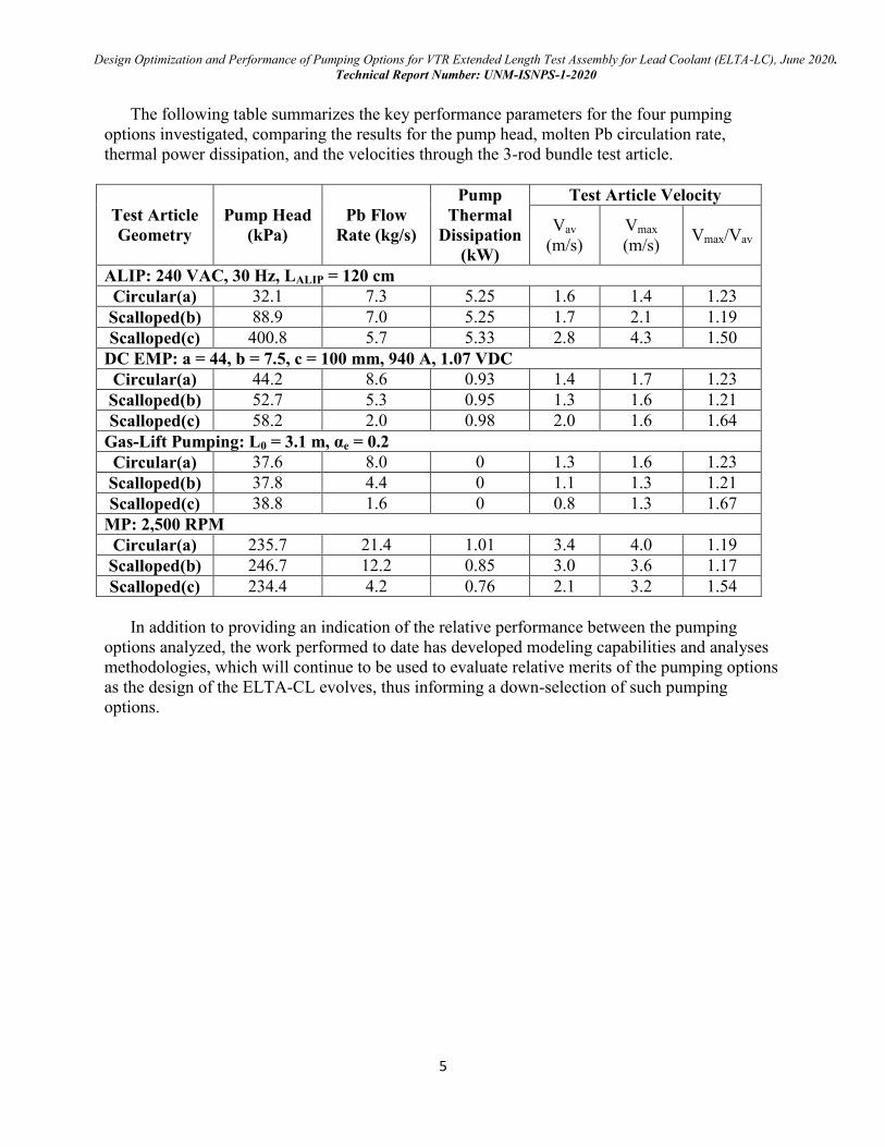
The following table summarizes the key performance parameters for the four pumping
options investigated, comparing the results for the pump head, molten Pb circulation rate,
thermal power dissipation, and the velocities through the 3-rod bundle test article.
Test Article
Geometry
Pump Head
(kPa)
Pb Flow
Rate (kg/s)
Pump
Thermal
Dissipation
(kW)
Test Article Velocity
Vav
(m/s)
Vmax
(m/s) Vmax/Vav
ALIP: 240 VAC, 30 Hz, LALIP = 120 cm
Circular(a) 32.1 7.3 5.25 1.6 1.4 1.23
Scalloped(b) 88.9 7.0 5.25 1.7 2.1 1.19
Scalloped(c) 400.8 5.7 5.33 2.8 4.3 1.50
DC EMP: a = 44, b = 7.5, c = 100 mm, 940 A, 1.07 VDC
Circular(a) 44.2 8.6 0.93 1.4 1.7 1.23
Scalloped(b) 52.7 5.3 0.95 1.3 1.6 1.21
Scalloped(c) 58.2 2.0 0.98 2.0 1.6 1.64
Gas-Lift Pumping: L0 = 3.1 m, αe = 0.2
Circular(a) 37.6 8.0 0 1.3 1.6 1.23
Scalloped(b) 37.8 4.4 0 1.1 1.3 1.21
Scalloped(c) 38.8 1.6 0 0.8 1.3 1.67
MP: 2,500 RPM
Circular(a) 235.7 21.4 1.01 3.4 4.0 1.19
Scalloped(b) 246.7 12.2 0.85 3.0 3.6 1.17
Scalloped(c) 234.4 4.2 0.76 2.1 3.2 1.54
In addition to providing an indication of the relative performance between the pumping
options analyzed, the work performed to date has developed modeling capabilities and analyses
methodologies, which will continue to be used to evaluate relative merits of the pumping options
as the design of the ELTA-CL evolves, thus informing a down-selection of such pumping
options.
Design Optimization and Performance of Pumping Options for VTR Extended Length Test Assembly for Lead Coolant (ELTA-LC), June 2020.
Technical Report Number: UNM-ISNPS-1-2020
6
Table of Contents
1. Executive Summary 2
List of Figures 7
List of Tables 11
Nomenclature 12
2. Introduction 14
3. VTR ELTA-CL thermal hydraulic model development and analyses 17
4. Annular Linear Induction Pump (ALIP), design optimization and performance 22
5. DC conduction EM Pump (EMP) design optimization and analyses 28
6. Modeling and performance results of VTR ELTA-CL with gas-lift pumping 34
7. Design optimization and performance results with axial-centrifugal flow
Mechanical Pumps (MPs) 40
8. Performance comparison of pumping options investigated for the VTR ELTA-CL 49
9. Summary and closing remarks 52
10. Planned and proposed future work 54
Acknowledgements 56
References 57
Design Optimization and Performance of Pumping Options for VTR Extended Length Test Assembly for Lead Coolant (ELTA-LC), June 2020.
Technical Report Number: UNM-ISNPS-1-2020
7
List of Figures
Fig. 1: Assumed sectional views and dimensions of the assumed VTR ELTA-CL for the
purpose of performing the parametric analyses and calculating the demand curves for the
different pumping options investigated (Actual design being developed by Los Alamos
National Laboratory could be different). 17
Figure 2: Cross-sections of 3-rod test bundle geometries investigated in present analyses to
quantify the effects on the total pressure losses, and the molten lead flow rate and
average and maximum velocities in a 3-rod test article, at 500°C lead exit temperature,
for a fuel rod total length of 1.60 m and active length of 0.8 m. Recently the rod total
length has recently been reduced by the VTR ELTA-CL team to only 1.0 m (0.50 m
active length). Therefore, actual results would be different from those presented in this
interim report. The effects of reducing the active rod length, together with other design
parameters, are currently being investigated. 18
Fig. 3: Calculated velocity contours in 3D thermal-hydraulic analyses of molten lead flow in
the 3-rod bundle geometries in Fig. 2, with and without scalloped shroud walls, at Tin =
420°C, Tex = 500°C, and mass flow rate, ṁ = 6 kg/s. 19
Fig. 4: Calculated average velocity and the maximum-to-average flow velocity ratios for the
three bundle geometries in Figs. 2, 3. Results are for a molten lead exit temperature of
500°C. 20
Fig. 5: Cross sectional and isometric views of the developed ALIP design for the assumed
VTR ELTA-CL. This ALIP has a diameter, including 1.0 mm thick metal casing, of 6.5
cm and could operate at terminal voltage or either 120 or 240 VAC and frequencies of
30 or 60 Hz. The active length, LALIP, of the ALIP in this Figure is 1.2 m and the total
length is 1.3 m, including 0.05 m inlet and exit flow guide section. 22
Fig. 6: Equivalent circuit for ALIP, with Rcoils being the stator coils resistance, Xe the stator
coils leakage reluctance, Xm, the magnetic reluctance, Rw,out and Rw,in the outer and inner
wall equivalent resistances, and Rf/s the equivalent resistance of the liquid metal. 23
Fig. 7: Comparison of UNM-ISNPS ALIP model predictions to experimental data of Polzin
et al. (2010) for a NASA prototype ALIP in a liquid NaK-78 loop. 24
Fig. 8: The calculated supply curves for the developed ALIP designs of active length, L, of
0.9 m and 1.2 m (or total length of 1.0 m and 1.3 m, including 0.05 m long inlet and exit
flow guide sections) and the demand curves for the assumed ELTA-CL in Fig. 1 at
molten lead exit temperature of 500°C and for 3-rod bundles without and with scalloped
walls. 25
Fig. 9: Bar chart comparisons of the pressure heads and mass flow of molten lead
achievable in the ELTA-CL (Fig. 1) using the developed ALIP designs of active length,
LALIP, of 0.9 m and 1.2 m (or total length of 1.0 m and 1.3 m, including 0.05 m long inlet
and exit flow guide sections) and operating at 240 VAC terminal voltage and current
frequency of 30 and 60 Hz. These results are for 1.6 m total fuel rod length and active
length of 0.8 m. 25
Design Optimization and Performance of Pumping Options for VTR Extended Length Test Assembly for Lead Coolant (ELTA-LC), June 2020.
Technical Report Number: UNM-ISNPS-1-2020
8
Fig. 10: Bar chart comparisons of the average (bar height) and maximum (number inside the
bars) flow velocities achievable for molten flow in three bundle geometries in Figs. 2, 3,
using the developed ALIP designs of active length, LALIP, of 0.9 m and 1.2 m (or total
length of 1.0 m and 1.3 m, including 0.05 m long inlet and exit flow guide section) and
operating at 240 VAC terminal voltage and current frequency of 30 and 60 Hz. These
results are for a total length of the fuel rods in the bundles (Fig. 2) of 1.6 m and active
length of 0.8 m. 26
Fig. 11: Bar chart comparisons of the heat dissipation of the developed ALIP designs of
active length, LALIP, of 0.9 m and 1.2 m (or total length of 1.0 m and 1.3 m, including
0.05 m long inlet and exit flow guide sections) and operating at 240 VAC terminal
voltage and current frequency of 30 and 60 Hz. These results are for a total length of
the fuel rods in the bundles (Fig. 2) of 1.6 m and active length of 0.8 m. Pump heat
dissipation for selected ALIP designs at 240 VAC. 26
Fig. 12: Cross-section and isometric views of the optimized design of a miniature
submerged EMP placed in the riser of the VTR ELTA-CL (e.g., Fig. 1). In this figure,
EMP is placed near the top of the riser of the assumed VTR ELTA-CL, above the 3-rods
test bundle, and has total and rectangular duct lengths of 0.7 m and 0.5 m, respectively.
The difference is the length of the entrance section (0.20 m) for molten lead flow into the
EMP. 28
Fig. 13: Calculated magnetic field lines distribution at the upper poles of the developed
EMP with dual ALNICO 5 magnets for the VTR ELTA-CL. The width, b, of the molten
lead flow channel in this figure is 10 mm. 29
Fig. 14: Comparisons of the calculated characteristics and supply curves of the three EMP
designs investigated (Table 2), and the demand curves for the assumed VTR ELTA-CL
(Fig. 1) with three different geometries of the 3-rod bundle (Fig. 2). These results are for
a molten lead exit temperature of 500°C. The average and maximum flow velocities of
molten lead in the three different 3-rod bundle geometries are both much lower than 3
m/s. 31
Fig. 15: Bar chart comparisons of the achievable pressure heads (bar height) and mass flow
of molten lead (numbers inside the bars) in the assumed VTR ELTA-CL (Fig. 1) using
the developed EMP designs with a total length of 0.70 m, including a 0.20 m long flow
guide section. These results are for a total length of the fuel rods in the investigated 3-
rod bundle geometries (Fig. 2) of 1.6 m and active length of 0.8 m. 32
Fig. 16: Bar chart comparisons of the achievable average (bar height) and maximum flow
velocities (numbers inside the bars) of molten lead in the assumed VTR ELTA-CL (Fig.
1) using the developed EMP design with a total length of 0.70 m, including a 0.20 m
long flow guide section. These results are for a total length of the fuel rods in the
investigated 3-rod bundle geometries (Fig. 2) of 1.6 m and active length of 0.8 m. 32
Fig. 17: Bar chart comparisons of the thermal power dissipation by the developed EMP
designs in the assumed VTR ELTA-CL (Fig. 1) with three 3-rod bundle geometries
investigated (Fig. 2). The EMP has a total length of 0.70 m, including a 0.20 m long
flow guide section. These results are for a total length of the fuel rods in the investigated
3-rod bundle geometries (Fig. 2) of 1.6 m and active length of 0.8 m. 33
Design Optimization and Performance of Pumping Options for VTR Extended Length Test Assembly for Lead Coolant (ELTA-LC), June 2020.
Technical Report Number: UNM-ISNPS-1-2020
9
Fig. 18: A schematic of the VTR ELTA-CL with molten lead circulated using the gas-lift
pumping option involving the injection of inert gas (e.g., Argon) in the riser tube above
the 3-rod test bundle (Figs. 1 and 2). 34
Fig. 19: Comparisons of the predictions the developed Gas-lift model to the reported LBE-
N2 experimental data of Nishi et al. (2003). 35
Fig. 20: Comparisons of the predictions the developed Gas-lift model to the reported LBE-
Argon gas experimental data of Shi et al. (2018). 36
Fig. 21: Comparison of the performance curves of the gas-lift pumping option for the VTR
VTR ELTA-CL at a molten lead exit temperature of 500°C and with the 3-rod bundles
without and with scalloped shrouds (Fig. 2). 37
Fig. 22: Bar chart comparisons of the values of pressure head (bar height) and mass flow of
molten lead (numbers inside the bars) generated by the gas injection for circulating
molten lead in assumed VTR ELTA-CL (Fig. 1) with the 3-rod bundle geometries
investigated (Fig. 2). These results are for a total length of the fuel rods in the
investigated 3-rod bundle geometries (Fig. 2) of 1.6 m and active length of 0.8 m. 38
Fig. 23: Bar chart comparisons of the values of the achievable average (bar height) and
maximum (number inside the bar) flow velocities of molten lead circulating using the
gas-lift pumping option in the assumed VTR ELTA-CL (Fig. 1) with three 3-rod bundle
geometries investigated (Fig. 2). These results are for a total length of the fuel rods in
the investigated 3-rod bundle geometries (Fig. 2) of 1.6 m and active length of 0.8 m.
38
Fig. 24: Section view of showing a developed MP mounted at the exit of the riser tube of
the assumed VTR ELTA-CL (e.g., Fig. 1). Shown also are the impeller blades and flow
guide for directing discharged molten lead to flow down the annular downcomer. 40
Fig. 25. Photographs of the 3D printed plastic impeller of one of the developed miniature
MP design to be mounted at the exit of 6.0 cm diameter riser. This MP impeller was
optimized for maximum efficiency. 41
Fig. 26: UNM-ISNPS pump optimization methodology including pump design generation
using CAESES, variable genetic algorithm optimization using DAKOTA, and CFD
analyses using STAR-CCM+, showing the data flow between codes during the design
optimization iterations. 42
Fig. 27. Section view showing the calculated flow field and velocity vectors for an
optimized MP design at maximum pumping power for molten lead flow rate at of 15
kg/s at 500 °C, and impeller rotation speed of 2,500 RPM. 43
Fig. 28: Velocities of the molten Pb flow along the surface and at tip of the MP impeller
blades of the MP design optimized for maximum pumping power at impeller shat
rotation speeds of 1,500, 2,000, and 2,500 RPM, and for a Pb flow rate of 15 kg/s at
500°C. 44
Fig. 29: Calculated supply curves for the optimized MP design at different rotation speed of
the impeller shaft, as well as the demand curves of the VTR ELTA-CL with 3-rod
bundles of different geometries (Fig. 2). These curves are for molten lead exit
Design Optimization and Performance of Pumping Options for VTR Extended Length Test Assembly for Lead Coolant (ELTA-LC), June 2020.
Technical Report Number: UNM-ISNPS-1-2020
10
temperature of 500°C, and total and active length of the fuel rods (Fig. 1) of 1.6 m and
0.8 m, respectively. 46
Fig. 30: Bar Charts of the calculated pressure head (bar height) and mass flow of molten
lead (numbers inside the bars) for the optimized MP design at different rotation speed of
the impeller shaft for the VTR ELTA-CL with 3-rod bundles of different geometries
(Fig. 2). The presented results are for molten lead exit temperature of 500°C, and total
and active length of the fuel rods in the test bundles (Fig. 1) of 1.6 and 0.8 m,
respectively. 46
Fig. 31: Bar Charts of the calculated average (bar height) and maximum flow velocities
(numbers inside the bars) with the optimized MP design at different rotation speed of the
impeller shaft for the VTR ELTA-CL with 3-rod bundles of different geometries (Fig.
2). The results are for molten lead exit temperature of 500°C, and total and active length
of fuel rods in the test bundles (Fig. 1) of 1.6 m and 0.8 m, respectively. 47
Fig. 32: Bar Charts of the calculated heat dissipation by the optimized MP design at
different rotation speed of the impeller shaft for the VTR ELTA-CL with 3-rod bundles
of different geometries (Fig. 2). The results are for molten lead exit temperature of
500°C, and total and active length of the fuel rods in the test bundles (Fig. 1) of 1.6 m
and 0.8 m, respectively. 48
Fig. 33: Bar Charts comparison of the generated pumping pressure head (bar height) and the
corresponding circulation flow rate (numbers inside the bars) of the molten lead using
the four pumping option investigated in this work at UNM-ISNPS for the assumed VTR
ELTA-CL (Fig. 1) with 3-rod bundles of different geometries (Fig. 2). The presented
results are for molten lead exit temperature of 500°C, and total and active length of the
fuel rods in the test bundles (Fig. 1) of 1.6 m and 0.8 m, respectively. 49
Fig. 34: Bar Charts comparison of the attainable average (bar height) and maximum
(numbers inside the bars) velocities of molten lead flow in the 3-rod bundles of different
geometries (Fig. 2) the assumed VTR ELTA-CL (Fig. 1) with using the four pumping
option investigated in this work. The presented results are for molten lead exit
temperature of 500°C, and total and active length of the fuel rods in the test bundles
(Fig. 1) of 1.6 m and 0.8 m, respectively. 50
Fig. 35: Bar Charts comparison of the dissipated thermal power by the investigated four
pumping options for circulating molten lead in the assumed VTR ELTA-CL (Fig. 1)
with 3-rod bundles of different geometries (Fig. 2). The presented results are for molten
lead exit temperature of 500°C, and total and active length of the fuel rods in the test
bundles (Fig. 1) of 1.6 m and 0.8 m, respectively. 51
Design Optimization and Performance of Pumping Options for VTR Extended Length Test Assembly for Lead Coolant (ELTA-LC), June 2020.
Technical Report Number: UNM-ISNPS-1-2020
11
List of Tables
Table 1: Geometric parameters and dimensions of 3-rod bundle configurations of the
assumed ELTA-CL for performing thermal hydraulic analyses (Fig. 1) for
calculating the demand curves with the different pumping options. (Actual design
being developed by LANL could be different). 19
Table 2: Design parameters of DC conduction EMP designs for 60.0 mm pump footprint
with their computed magnetic flux and maximum recommended currents and total
length of 0.70 m, including 0.2 m inlet flow guide section. 30
Table 3: Comparison of the performance figures of the four pumping options investigated or
ELTA-CL with 3-rod bundles of different geometries at molten lead exit temperature of
500°C. This comparison is for total and active length of the fuel rods in the test bundles
(Fig. 1) of 1.6 m and 0.8 m, respectively. 52
Design Optimization and Performance of Pumping Options for VTR Extended Length Test Assembly for Lead Coolant (ELTA-LC), June 2020.
Technical Report Number: UNM-ISNPS-1-2020
12
Nomenclature
a EMP flow channel depth (m)
Ac Cross sectional flow area (m2)
αe Exit void fraction (-)
ALIP Annular Linear Induction Pump
ANL Argonne National Laboratory
B Magnetic field strength (G)
b EMP flow channel width (mm)
c EMP flow channel length (mm)
CFD Computational Fluid Dynamics
d Fuel rod outer diameter (mm)
D Bundle shroud diameter (mm)
De Equivalent hydraulic diameter (mm)
δ Rod bundle minimum wall spacing (mm)
EMP Electromagnetic Pump
HTR High Temperature Reactor
I Electric current (A)
IEEE Institute of Electrical and Electronics Engineers
INL Idaho National Laboratory
ISNPS Institute for Space and Nuclear Power Studies
L0 Gas lift pumping rise length (m)
LALIP ALIP active length (m)
LANL Los Alamos National Laboratory
LBE Lead-Bismuth Eutectic
ELTA-CL Extended Length Test Assembly for Lead Coolant
LFR Lead cooled Fast Reactor
Design Optimization and Performance of Pumping Options for VTR Extended Length Test Assembly for Lead Coolant (ELTA-LC), June 2020.
Technical Report Number: UNM-ISNPS-1-2020
13
MP Mechanical Pump
MSR Molten Salt Reactor
ORNL Oak Ridge National Laboratory
P Fuel rod pitch (mm)
P/d Fuel rod pitch-diameter ratio (-)
PNNL Pacific Northwest Nation Laboratory
Rcoils Stator coils resistance ()
Rf/s Equivalent resistance of the liquid metal ()
Rw,in Inner wall equivalent resistance ()
Rw,out Outer wall equivalent resistance ()
SFR Sodium cooled Fast Reactor
SRNL Savannah River National Laboratory
Tin Molten lead inlet temperature (K)
Tex Molten lead exit temperature (K)
Xe Stator coils leakage reluctance
Xm, Magnetic reluctance
WP Wetted Perimeter (mm)
UNM University of New Mexico
VTR Versatile Test Reactor
Design Optimization and Performance of Pumping Options for VTR Extended Length Test Assembly for Lead Coolant (ELTA-LC), June 2020.
Technical Report Number: UNM-ISNPS-1-2020
14
2. Introduction
In February 2019 the U.S. Department of Energy announced the plan to build a Versatile
Test Reactor, or VTR, to establish the capability to perform irradiation testing at neutron flux
that is much higher than currently available in existing test/research reactors, in support of the
development of Generation-IV (GEN-IV) and advanced nuclear reactor concepts and
technologies. This ~300 MW sodium cooled, pool-type, fast test reactor would provide a wide
range of in-pile testing environments representative of advanced reactors operating with various
coolants such as liquid sodium, liquid lead, molten salt and gas. The results would support the
developments of the Molten Salt Reactor (MSR), High-Temperature gas cooled Reactor (HTR)
and Gas cooled Fast Reactor (GFR), Sodium Fast Reactor (SFR), and Molten Lead Reactor
(LFR). This unique capability will help accelerate testing of advanced nuclear fuels, materials,
instrumentation, and sensors. In addition, it would help modernize the nation’s infrastructure for
conducting essential nuclear energy research and development that are crucial to advancing the
technology and materials testing in support of the U.S. nuclear energy industry.
The VTR project is led by Idaho National Laboratory (INL) in partnership with five DOE
laboratories. These include Argonne National Laboratory (ANL), Los Alamos National
Laboratory (LANL), Oak Ridge National Laboratory (ORNL), Pacific Northwest National
Laboratory (PNNL), and Savannah River National Laboratory (SRNL). The VTR project team
also includes a host of industry and university partners. The design of the VTR, which could be
completed as early as 2026, would be constructed at a site to be selected at one of the DOE’s
National Laboratories.
The Gen-IV LFR concept is being developed by Westinghouse to provide safe, sustainable,
efficient, and economical generation of electricity to the local and the global markets. This 950
MWt (~460 MWe) pool-type reactor, with in-vessel lead-to-supercritical CO2 heat exchangers
would nominally operate at ~500°C in the demonstration phase, and up to 700°C in follow-on
plant versions consistent with progress in material development. Such high temperature
operation, while benefitting plant economics through an increased efficiency, raises challenges,
particularly those associated with potential liquid lead corrosion and erosion of primary system
components such as fuel rod cladding and heat exchangers. Resolving these challenges is
important to ensuring safe and reliable operation for the entire operating life of the LFR.
Furthermore, the issue of material transport within the LFR system is critical to the longevity of
this reactor concept. This is particularly important since some components, such as the reactor
vessel and the primary pumps, would operate at cold leg temperature (~400°C), while others,
such fuel cladding and upper core structures, and would experience higher temperatures.
To address these and other challenges in support of the development of the LFR, the ELTA-
CL is being designed for testing fuels and materials of interest. The compact and self-enclosed in
pile ELTA-CL will be placed at a designated location in the VTR core, effectively replacing a
VTR fuel assembly. The ELTA-CL will support the development of the LFR, for example by
performing corrosion testing of candidate materials in a prototypical irradiation environment, and
by demonstrating potential fuel concepts and instrumentation options. Los Alamos National
Laboratory (LANL) is leading the design development of the VTR ELTA-CL, with
Westinghouse supporting this effort as one of the potential users of this in-pile test assembly.
Other supporting organizations include the University of Pittsburgh for instrumentation
development, and the University of New Mexico (UNM) for performing out-of-pile materials
corrosion testing in a molten lead loop, and for investigating pumping options for circulating
molten lead in the VTR ELTA-CL. The latter effort is being carried out by UNM’s Institute for
Design Optimization and Performance of Pumping Options for VTR Extended Length Test Assembly for Lead Coolant (ELTA-LC), June 2020.
Technical Report Number: UNM-ISNPS-1-2020
15
Space and Nuclear Power Studies (UNM-ISNPS) and is the focus of this preliminary technical
report, covering the work done in the period from December 2019 to June 2020.
The University of New Mexico’s Institute for Space and Nuclear Power studies has been
tasked with conducting feasibility studies and performing preliminary designs, modeling, and
performance evaluation of different pumping options for the VTR ELTA-CL. Three-dimensional
Computational Fluid Dynamic (CFD) analyses are performed to calculate the velocity field of
molten lead flow through different 3-fuel rod bundle geometries and determine the values of the
average flow velocities as well as the values and the locations of the maximum velocities in these
test bundle geometries with circular and scalloped shroud walls. These CFD analyses used a total
fuel rod length in the test bundles of 1.6 m, and active fuel length of 0.80 m. Future
investigations, informed by the results obtained so far, will investigate the possibility of
increasing the number of fuel rods in the test bundles from three to seven. This will be supported
by the possibility to reduce the total and the active length the rods to 1.0 m and 0.5 m,
respectively. This latter modification, through a reduction in pressure drop through the ELTA-
CL, is anticipated to ease pump design and/or help achieving lead velocity goals.
The four pumping options investigated for the VTR ELTA-CL are: (a) gas lift pumping, (b)
immersed Annular Linear Induction Pump (ALIP), (c) immersed Electromagnetic Pump (EMP),
and (d) Centrifugal flow mechanical pump (MP).
The gas-lift pumping option enhances circulation of molten lead through the VTR ELTA-CL
by injecting argon gas at a very low rate into the riser tube (assumed 6.0 cm in diameter) close to
the exit from the 3-rods test bundle. The injected gas decreases the average density of the molten
lead-gas mixture in the riser, which increases the driving force for natural circulation throughout
the VTR ELTA-CL. This pumping option is fully passive, and the performance depends on the
average void fraction of the gas-molten lead mixture in the riser, the height of the riser, and to a
lesser extent on the inner diameter of the riser tube.
To evaluate the potential of the gas-lift pumping option, the objectives are to investigate the
effect of the injection rate of the gas in the riser tube on the molten lead circulation rate in the
VTR ELTA-CL, while keeping the molten lead-gas mixture in the riser in the bubbly flow
regime, with an exit void fraction < 0.20. To demonstrate the latter, the effort of evaluating the
performance of the gas-lift pumping option developed a flow regime map for the molten lead /
argon gas mixture in the riser. It is used to investigate the possible ranges of the gas injection rate
into the riser and to ensure operating in the bubbly flow regime. The developed VTR ELTA-CL
model with gas-lift pumping is validated against reported data for LBE-N2 gas and LBE-Argon
gas generated in experimental loops built and operated in Japan and China.
The ALIP for circulating the molten lead in the VTR ELTA-CL drives the flow through a
narrow annular channel along the pump length using a linearly traveling magnetic field. This
field is produced by three phase Alternative Current (AC) that passes through Copper (Cu) wire
windings in the form of flat “pancake” coils. The traveling magnetic field produces electrical
currents in the liquid metal flowing through the annular duct in the pump. This current interacts
with the magnetic field produced by the Cu coils to generate the force for driving the molten lead
flow. The design optimization and performance analyses of the ALIP investigated the effects of
varying the ALIP total length, the applied terminal voltage and frequency on the pump
characteristics. The current ALIP design employs Teflon insulated Cu coils, which would require
active cooling using forced gas or oil to maintain their temperature below 148°C (Baker and
Tessier, 1987). Proposed future effort would investigate using ceramic insulated Cu coils that
could operate at temperatures up to 500°C without active cooling.
Design Optimization and Performance of Pumping Options for VTR Extended Length Test Assembly for Lead Coolant (ELTA-LC), June 2020.
Technical Report Number: UNM-ISNPS-1-2020
16
The optimized EMP design employs dual permeant magnets and high current 700- 1,100 A,
low terminal voltage (< 2 VDC) power supply, depending on the dimensions of the flow duct
with the pump. This effort investigated the effect of changing the duct dimensions on the
miniature, submerged EMP characteristics at 500°C. At this temperature, with the selected
magnet and structure materials this pump does not need active cooling.
The optimized Mechanical Pump (MP) designs are of an axial-centrifugal flow type. The MP
could be mounted with a fitted shroud at the top of the riser of the VTR ELTA-CL. The
optimized MP designs investigated, for a riser tube diameter of 6.0 cm, the effects of the
optimization methods on the calculated performance characteristic and the flow field in the
impeller blades and in the ELTA-CL riser tube and downcomer.
Investigated MP designs include those optimized for maximum efficiency, maximum
pumping power and maximum pumping head, at both low and high mass flows of molten lead.
The design optimized for maximum pumping power at a flow rate of 14 kg/s and 500oC molten
lead gave the best characteristic. This design however does not generate the maximum pressure
head at the deadhead conditions, but at an intermediate flow rate. The decrease in the pump head
with decreasing flow rate is due to the losses caused by the generation of eddy flow vortices
between the impeller blades, and between the blades and the pump casing. Detailed CFD
analyses are conducted to investigate the effect of the rotation speed of the impeller shaft and the
design optimization method on the pump performance and the velocity field along the surface of
the impeller blades both in the riser and in the downcomer of the VTR ELTA-CL.
The following four sections detail the work done to date on the design optimization and
performance evaluation of the four pumping options investigated for the VTR ELTA-CL. The
calculated characteristics for these pumping options are presented and compared to the calculated
demand curves using a developed VTR ELTA-CL model. Also compared are the attainable
pressure head and the average and maximum flow velocities of molten lead through 3-rod test
bundles of different geometries, and the thermal power dissipation associated with using the
ALIP, EMP, and MP pumping options for the VTR ELTA-CL. It is noteworthy that there is no
heat dissipation associated with using the gas-lift pumping option.
The fifth section (Chapter 8) compares side by side the performance of the four pumping
options investigated, including the achievable pumping head and molten lead flow rate in the
VTR ELTA-CL with approximate dimensions, the thermal power dissipation, the average flow
velocity through three geometers of the 3-rod test bundles, as well as the value and the location
of maximum flow velocity in the bundle.
A summary and closing remarks section (Chapter 9) is provided at the end of this report. It
elaborates the critical findings to date of this preliminary effort of investigating miniature
pumping options for the VTR ELTA-CL. The last section (Chapter 10) lists planned and
proposed technical tasks for future work to improve the design and enhance the performance of
the different pumping options and to support future down selection.
Design Optimization and Performance of Pumping Options for VTR Extended Length Test Assembly for Lead Coolant (ELTA-LC), June 2020.
Technical Report Number: UNM-ISNPS-1-2020
17
3. VTR ELTA-CL thermal hydraulic model development and analyses
A thermal hydraulics model for the assumed VTR ELTA-CL dimensions (Fig. 1) is
developed to generate the demand curves with the optimized designs of the ALIP, EMP and MP
as well as those associated with using the gas lift pumping option. The developed physics-based
model is modular and could easily be applied to future design of the VTR ELTA-CL design. Fig.
1 presents the assumed VTR ELTA-CL geometry with 3-rod bundle test article. However, the
actual design currently being developed by Los Alamos National Laboratory could be different.
For the same fuel rod diameter, total and active lengths, and pitch-to-diameter ratio, the
developed model is used in conjunction with 3-D CFD analyses of the flow in a circular shroud
3-rod bundle and two scalloped shroud bundles, with increasingly reduced flow area. Scalloping
the shroud wall of the 3-rod bundles increases the total pressure losses, and decreases the flow
rate of molten lead through the 3-rod bundles, but could increase the ratio of the maximum to the
average flow velocities in the bundles for materials corrosion and compatibility tests. Scalloping
the bundle wall reduces the flow area adjacent to the wall, shifting a greater fraction of the flow
to travel through the central channel and increasing the flow velocity along the fuel rod cladding.
The developed ALIP, EMP and MP could be placed in the riser tube of the VTR ELTA-CL,
above the 3-rod test article (Fig. 1). The pressure-flow rate demand curves for the assumed VTR
ELTA-CL (Fig. 1) are calculated for three geometries of the test article bundle, namely: Circular
(a), wide Scalloped (b), and narrow Scalloped (c) (Fig. 2 and Table 1).
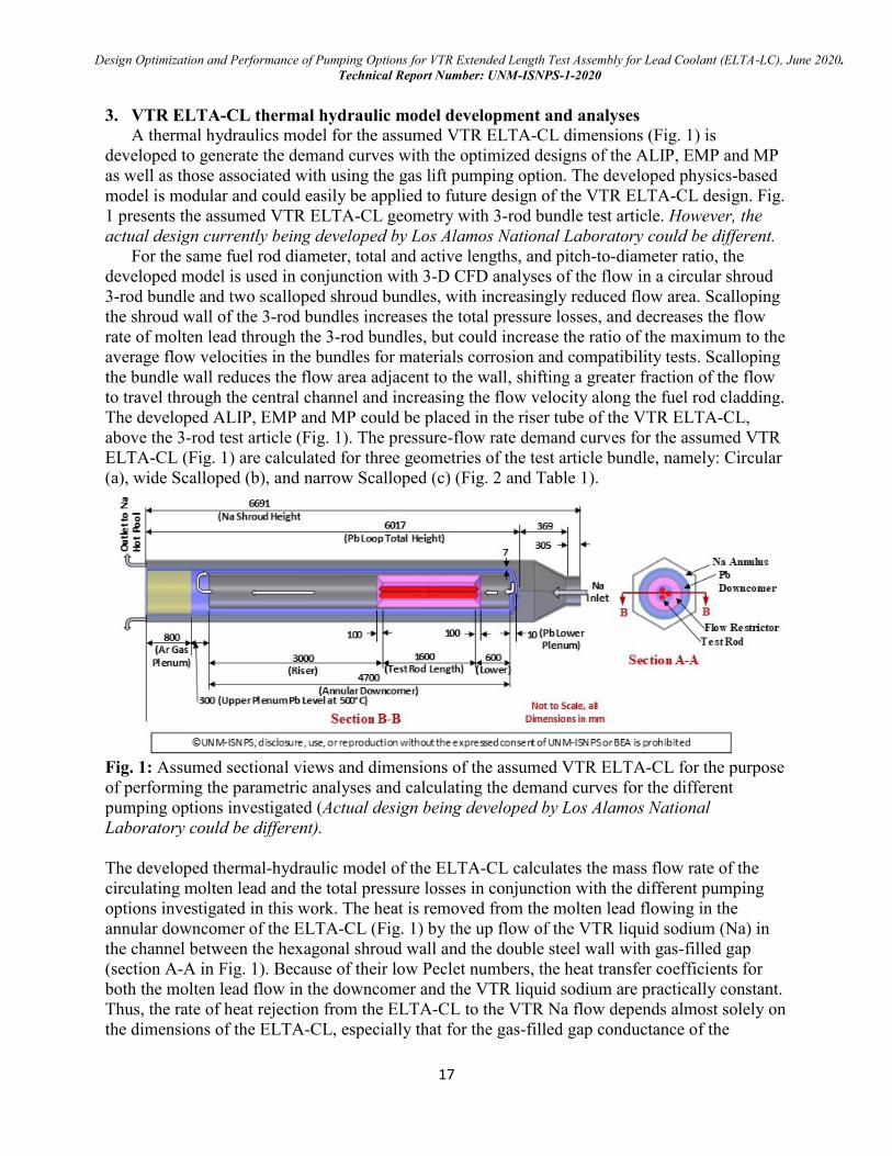
Fig. 1: Assumed sectional views and dimensions of the assumed VTR ELTA-CL for the purpose
of performing the parametric analyses and calculating the demand curves for the different
pumping options investigated (Actual design being developed by Los Alamos National
Laboratory could be different).
The developed thermal-hydraulic model of the ELTA-CL calculates the mass flow rate of the
circulating molten lead and the total pressure losses in conjunction with the different pumping
options investigated in this work. The heat is removed from the molten lead flowing in the
annular downcomer of the ELTA-CL (Fig. 1) by the up flow of the VTR liquid sodium (Na) in
the channel between the hexagonal shroud wall and the double steel wall with gas-filled gap
(section A-A in Fig. 1). Because of their low Peclet numbers, the heat transfer coefficients for
both the molten lead flow in the downcomer and the VTR liquid sodium are practically constant.
Thus, the rate of heat rejection from the ELTA-CL to the VTR Na flow depends almost solely on
the dimensions of the ELTA-CL, especially that for the gas-filled gap conductance of the
Design Optimization and Performance of Pumping Options for VTR Extended Length Test Assembly for Lead Coolant (ELTA-LC), June 2020.
Technical Report Number: UNM-ISNPS-1-2020
18
dividing double wall. For a lead exit temperature of 500oC, the VTR ELTA-CL model calculates
the molten lead inlet temperature to the 3-rod test article and the corresponding rod linear power.
These performance parameters are used in 3-D, CFD analyses of the test rod bundles to calculate
the flow velocity field and both the average and maximum flow velocities in the bundles.
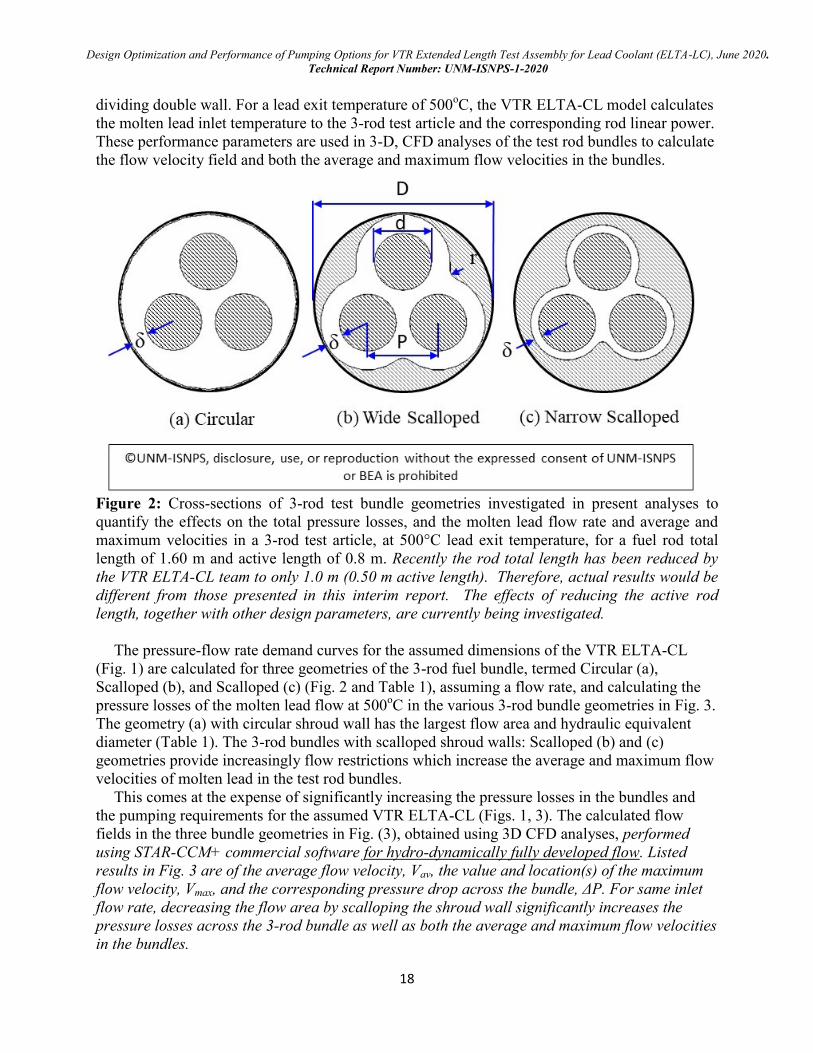
Figure 2: Cross-sections of 3-rod test bundle geometries investigated in present analyses to
quantify the effects on the total pressure losses, and the molten lead flow rate and average and
maximum velocities in a 3-rod test article, at 500°C lead exit temperature, for a fuel rod total
length of 1.60 m and active length of 0.8 m. Recently the rod total length has been reduced by
the VTR ELTA-CL team to only 1.0 m (0.50 m active length). Therefore, actual results would be
different from those presented in this interim report. The effects of reducing the active rod
length, together with other design parameters, are currently being investigated.
The pressure-flow rate demand curves for the assumed dimensions of the VTR ELTA-CL
(Fig. 1) are calculated for three geometries of the 3-rod fuel bundle, termed Circular (a),
Scalloped (b), and Scalloped (c) (Fig. 2 and Table 1), assuming a flow rate, and calculating the
pressure losses of the molten lead flow at 500oC in the various 3-rod bundle geometries in Fig. 3.
The geometry (a) with circular shroud wall has the largest flow area and hydraulic equivalent
diameter (Table 1). The 3-rod bundles with scalloped shroud walls: Scalloped (b) and (c)
geometries provide increasingly flow restrictions which increase the average and maximum flow
velocities of molten lead in the test rod bundles.
This comes at the expense of significantly increasing the pressure losses in the bundles and
the pumping requirements for the assumed VTR ELTA-CL (Figs. 1, 3). The calculated flow
fields in the three bundle geometries in Fig. (3), obtained using 3D CFD analyses, performed
using STAR-CCM+ commercial software for hydro-dynamically fully developed flow. Listed
results in Fig. 3 are of the average flow velocity, Vav, the value and location(s) of the maximum
flow velocity, Vmax, and the corresponding pressure drop across the bundle, ΔP. For same inlet
flow rate, decreasing the flow area by scalloping the shroud wall significantly increases the
pressure losses across the 3-rod bundle as well as both the average and maximum flow velocities
in the bundles.
Design Optimization and Performance of Pumping Options for VTR Extended Length Test Assembly for Lead Coolant (ELTA-LC), June 2020.
Technical Report Number: UNM-ISNPS-1-2020
19
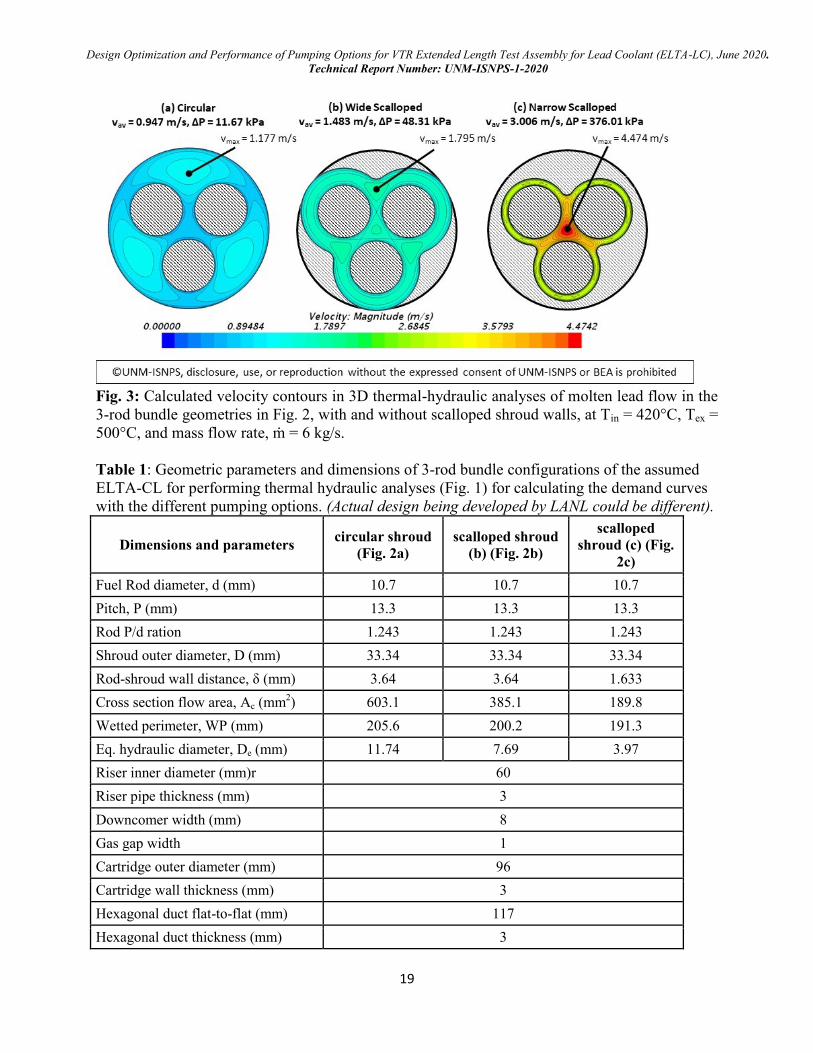
Fig. 3: Calculated velocity contours in 3D thermal-hydraulic analyses of molten lead flow in the
3-rod bundle geometries in Fig. 2, with and without scalloped shroud walls, at Tin = 420°C, Tex =
500°C, and mass flow rate, ṁ = 6 kg/s.
Table 1: Geometric parameters and dimensions of 3-rod bundle configurations of the assumed
ELTA-CL for performing thermal hydraulic analyses (Fig. 1) for calculating the demand curves
with the different pumping options. (Actual design being developed by LANL could be different).
Dimensions and parameters circular shroud
(Fig. 2a)
scalloped shroud
(b) (Fig. 2b)
scalloped
shroud (c) (Fig.
2c)
Fuel Rod diameter, d (mm) 10.7 10.7 10.7
Pitch, P (mm) 13.3 13.3 13.3
Rod P/d ration 1.243 1.243 1.243
Shroud outer diameter, D (mm) 33.34 33.34 33.34
Rod-shroud wall distance, δ (mm) 3.64 3.64 1.633
Cross section flow area, Ac (mm2) 603.1 385.1 189.8
Wetted perimeter, WP (mm) 205.6 200.2 191.3
Eq. hydraulic diameter, De (mm) 11.74 7.69 3.97
Riser inner diameter (mm)r 60
Riser pipe thickness (mm) 3
Downcomer width (mm) 8
Gas gap width 1
Cartridge outer diameter (mm) 96
Cartridge wall thickness (mm) 3
Hexagonal duct flat-to-flat (mm) 117
Hexagonal duct thickness (mm) 3
Design Optimization and Performance of Pumping Options for VTR Extended Length Test Assembly for Lead Coolant (ELTA-LC), June 2020.
Technical Report Number: UNM-ISNPS-1-2020
20
The performed CFD analyses used the STAR-CCM+ commercial code (Siemens PLM, 2019)
to calculate the flow field of molten lead flow through the 3-rod bundle geometries investigated
(Figs. 2, 3), at the calculated molten lead average temperature in the 3-rod test bundles and same
inlet flow rate using the model.
Fig. 3 presents velocity contour plots of the molten lead flow in the three bundle geometries
investigated in this work (Figs. 2 and Table 1). Results in this figure include the average flow
velocity, the value and location of the maximum flow velocity, and the pressure losses across the
bundles (Fig. 3). The velocity contours for the Scalloped (b) bundle geometry indicate a
relatively uniform velocity distribution across the bundle, while the Circular (a) bundle has a
slightly greater velocity in the periphery area of the bundle. The most restrictive narrow
Scalloped (c) bundle experiences relatively uniform velocity along the outer periphery of the
bundle, however with more flow in the central channel resulting in a much higher maximum
velocity at the center. In the Circular (a) and Scalloped (b) bundle geometries, the maximum
flow velocity occurs near the bundle periphery, while in the Scalloped (c) bundle geometry the
maximum flow velocity occurs in the central channel (Fig. 3).
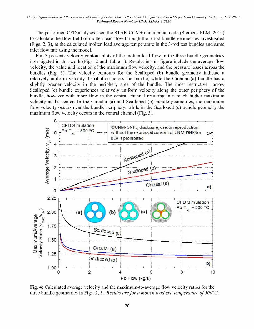
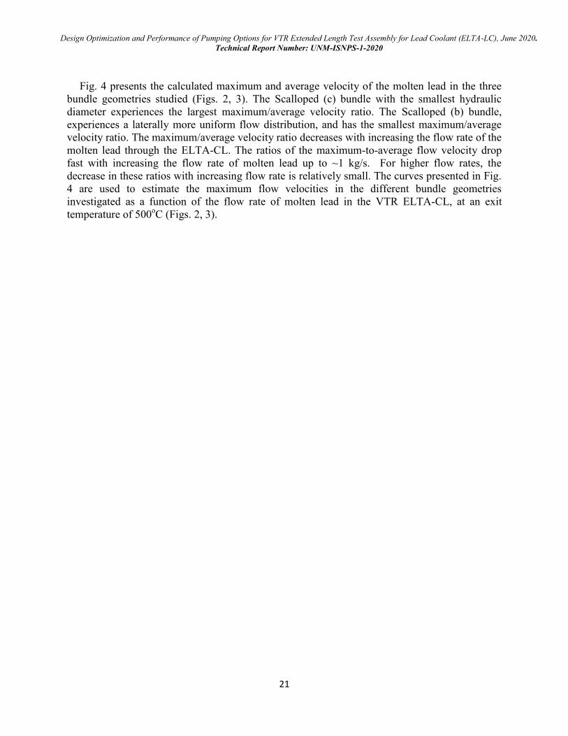
Fig. 4: Calculated average velocity and the maximum-to-average flow velocity ratios for the
three bundle geometries in Figs. 2, 3. Results are for a molten lead exit temperature of 500°C.
Design Optimization and Performance of Pumping Options for VTR Extended Length Test Assembly for Lead Coolant (ELTA-LC), June 2020.
Technical Report Number: UNM-ISNPS-1-2020
21
Fig. 4 presents the calculated maximum and average velocity of the molten lead in the three
bundle geometries studied (Figs. 2, 3). The Scalloped (c) bundle with the smallest hydraulic
diameter experiences the largest maximum/average velocity ratio. The Scalloped (b) bundle,
experiences a laterally more uniform flow distribution, and has the smallest maximum/average
velocity ratio. The maximum/average velocity ratio decreases with increasing the flow rate of the
molten lead through the ELTA-CL. The ratios of the maximum-to-average flow velocity drop
fast with increasing the flow rate of molten lead up to ~1 kg/s. For higher flow rates, the
decrease in these ratios with increasing flow rate is relatively small. The curves presented in Fig.
4 are used to estimate the maximum flow velocities in the different bundle geometries
investigated as a function of the flow rate of molten lead in the VTR ELTA-CL, at an exit
temperature of 500oC (Figs. 2, 3).
Design Optimization and Performance of Pumping Options for VTR Extended Length Test Assembly for Lead Coolant (ELTA-LC), June 2020.
Technical Report Number: UNM-ISNPS-1-2020
22
4. Annular Linear Induction Pump (ALIP), design optimization and performance
ALIPs have been widely used for circulating liquid metal coolants in liquid metal test loops
and fast test reactors. Examples are the compact ALIP being designed and fabricated for use in
the Na test loops in the TREAT reactor test facility at Idaho National Laboratory (Kelly personal
communication 2020) as well as the ALIP used in the experimental NaK-78 loop built at
Marshall Space Flight Center for space nuclear power research (Polzin, 2010). The sodium ALIP
design for TREAT operated at temperature < 150°C, and it at the NASA ALIP are cooled by
forced convection or air as they used organic insulated Cu coils. In comparison, the ALIP design
thought for the VTR ELTA-CL will be both smaller and more powerful. It also must operate
submerged in molten lead flow at the top of the riser tube, and is expected to operate at much
higher temperatures of at least 500°C.
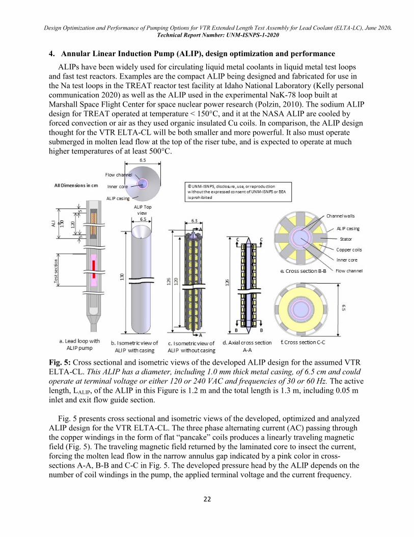
Fig. 5: Cross sectional and isometric views of the developed ALIP design for the assumed VTR
ELTA-CL. This ALIP has a diameter, including 1.0 mm thick metal casing, of 6.5 cm and could
operate at terminal voltage or either 120 or 240 VAC and frequencies of 30 or 60 Hz. The active
length, LALIP, of the ALIP in this Figure is 1.2 m and the total length is 1.3 m, including 0.05 m
inlet and exit flow guide section.
Fig. 5 presents cross sectional and isometric views of the developed, optimized and analyzed
ALIP design for the VTR ELTA-CL. The three phase alternating current (AC) passing through
the copper windings in the form of flat “pancake” coils produces a linearly traveling magnetic
field (Fig. 5). The traveling magnetic field returned by the laminated core to insect the current,
forcing the molten lead flow in the narrow annulus gap indicated by a pink color in cross-
sections A-A, B-B and C-C in Fig. 5. The developed pressure head by the ALIP depends on the
number of coil windings in the pump, the applied terminal voltage and the current frequency.
Design Optimization and Performance of Pumping Options for VTR Extended Length Test Assembly for Lead Coolant (ELTA-LC), June 2020.
Technical Report Number: UNM-ISNPS-1-2020
23
Increasing the number of coil winding assemblies increases the generated pressure head, but also
increases the length of the ALIP.
While the developed pressure head increases proportional to the applied terminal voltage, it
decreases with increasing current frequency. The ALIP designs developed by UNM-ISNPS for
the VTR ALIP require either 120 or 240VAC at 30 or 60 Hz and active cooling of the Cu coils to
maintain their temperature below 150oC. This temperature is limited by that for using organic
insulated Cu wire coils. Otherwise, high temperature ceramic insulated Cu coils will be required,
which is planned for future work.
Recently, an immersion ALIP pump with stainless steel sheathed, MgO insulated coil wires,
has been built and tested for the Indian Prototype Fast Breeder Reactor (Nashine, 2020). This
pump has been tested immersed in liquid Na at temperatures up to 550°C. This pump, however,
is large in diameter and short in length, 40 and 74.4 cm, respectively, and generates relatively
low pressure head of 400 kPa and flow rate of 0.5 kg/s as it was designed as a drain pump for the
reactor primary sodium.
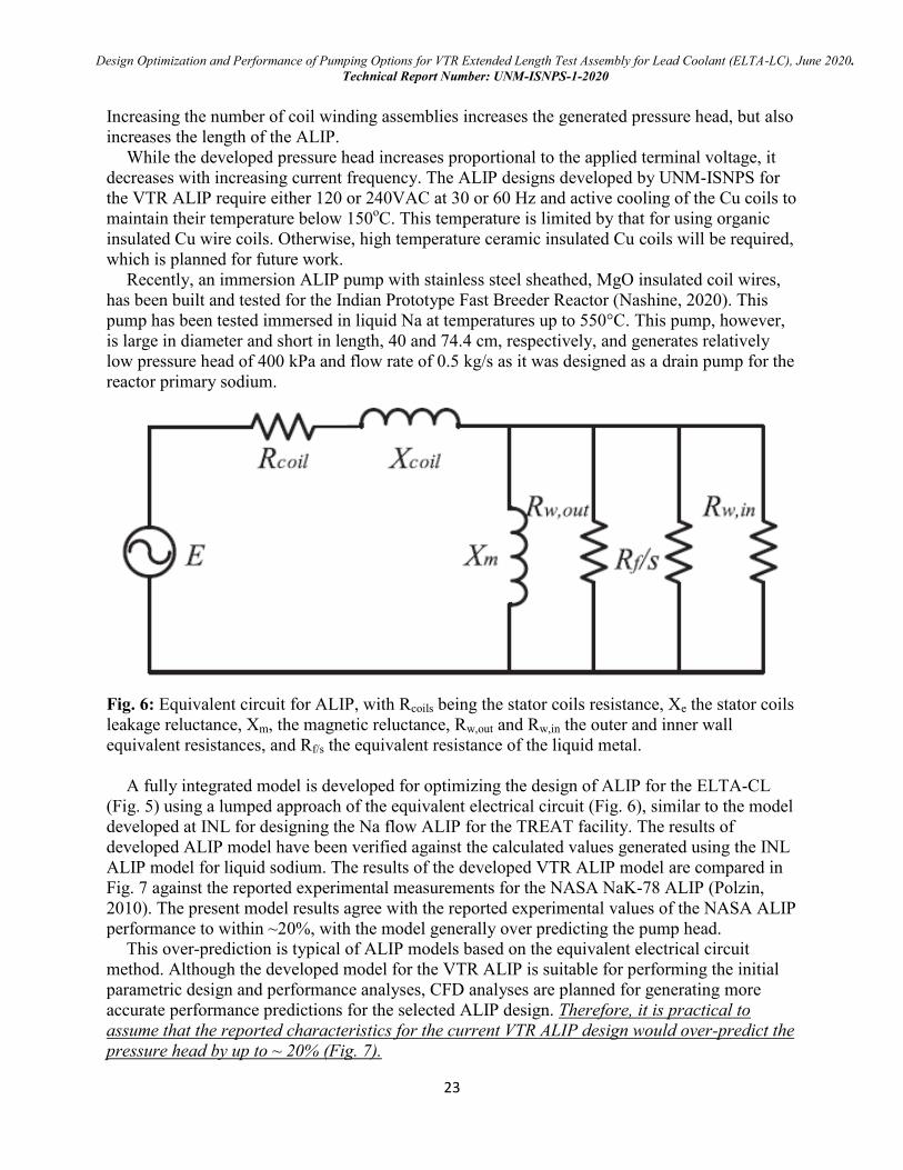
Fig. 6: Equivalent circuit for ALIP, with Rcoils being the stator coils resistance, Xe the stator coils
leakage reluctance, Xm, the magnetic reluctance, Rw,out and Rw,in the outer and inner wall
equivalent resistances, and Rf/s the equivalent resistance of the liquid metal.
A fully integrated model is developed for optimizing the design of ALIP for the ELTA-CL
(Fig. 5) using a lumped approach of the equivalent electrical circuit (Fig. 6), similar to the model
developed at INL for designing the Na flow ALIP for the TREAT facility. The results of
developed ALIP model have been verified against the calculated values generated using the INL
ALIP model for liquid sodium. The results of the developed VTR ALIP model are compared in
Fig. 7 against the reported experimental measurements for the NASA NaK-78 ALIP (Polzin,
2010). The present model results agree with the reported experimental values of the NASA ALIP
performance to within ~20%, with the model generally over predicting the pump head.
This over-prediction is typical of ALIP models based on the equivalent electrical circuit
method. Although the developed model for the VTR ALIP is suitable for performing the initial
parametric design and performance analyses, CFD analyses are planned for generating more
accurate performance predictions for the selected ALIP design. Therefore, it is practical to
assume that the reported characteristics for the current VTR ALIP design would over-predict the
pressure head by up to ~ 20% (Fig. 7).
Design Optimization and Performance of Pumping Options for VTR Extended Length Test Assembly for Lead Coolant (ELTA-LC), June 2020.
Technical Report Number: UNM-ISNPS-1-2020
24
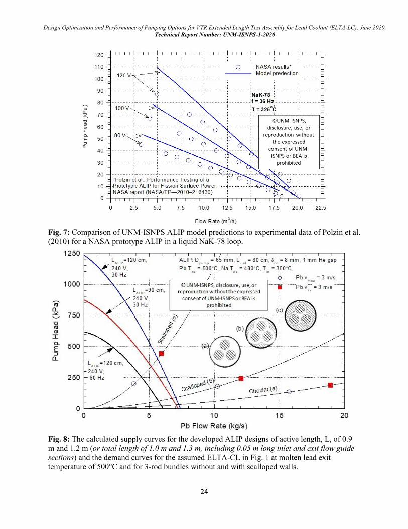
Fig. 7: Comparison of UNM-ISNPS ALIP model predictions to experimental data of Polzin et al.
(2010) for a NASA prototype ALIP in a liquid NaK-78 loop.
Fig. 8: The calculated supply curves for the developed ALIP designs of active length, L, of 0.9
m and 1.2 m (or total length of 1.0 m and 1.3 m, including 0.05 m long inlet and exit flow guide
sections) and the demand curves for the assumed ELTA-CL in Fig. 1 at molten lead exit
temperature of 500°C and for 3-rod bundles without and with scalloped walls.
Design Optimization and Performance of Pumping Options for VTR Extended Length Test Assembly for Lead Coolant (ELTA-LC), June 2020.
Technical Report Number: UNM-ISNPS-1-2020
25
The developed design model is used to generate the pump characteristics and investigate the
pump performance, when integrated into the assumed ELTA-CL in Fig. 1. The ALIP design has
an outer diameter of 6.5 cm, including 1.0 mm thick outer casing. The obtained pump
characteristics are for 60-240 VAC and different frequencies of 30-90 Hz. The pressure head and
flow rate increase with increasing load voltage, and /or with decreasing power current frequency.
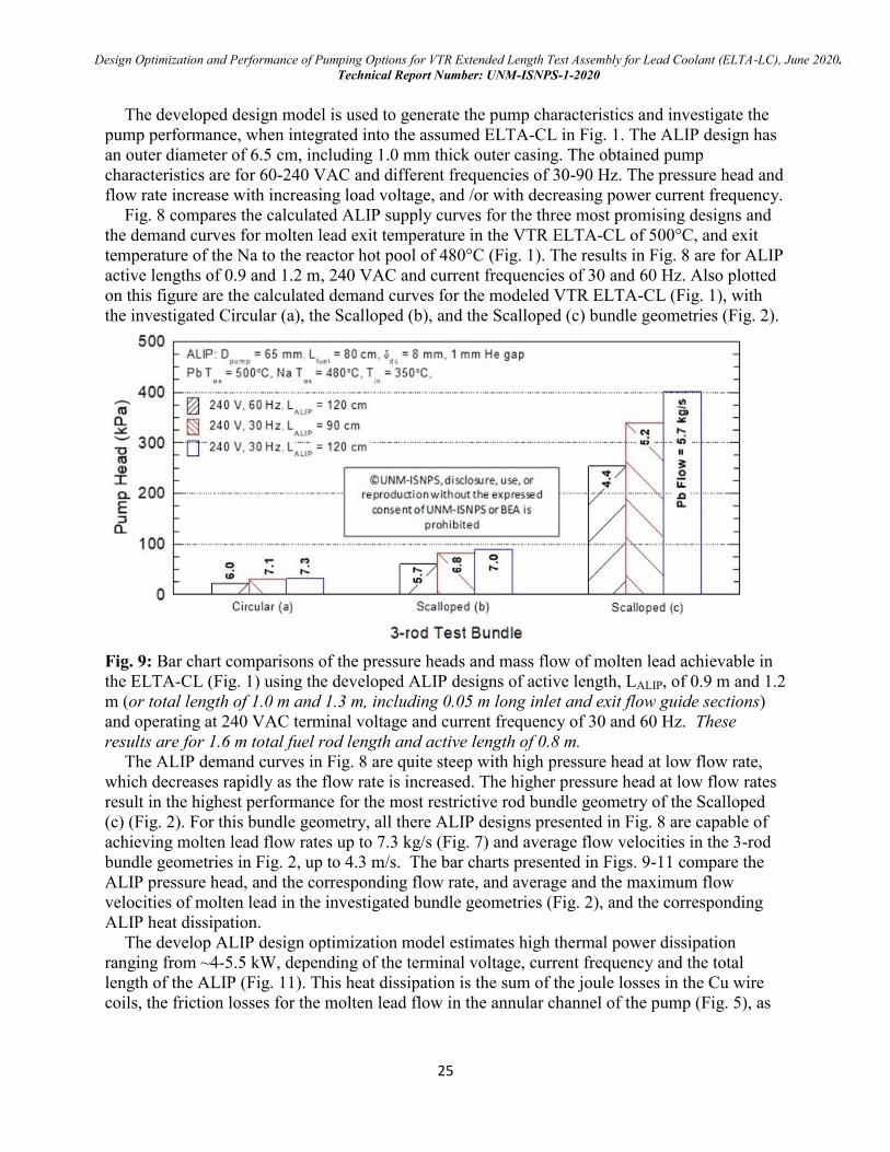
Fig. 8 compares the calculated ALIP supply curves for the three most promising designs and
the demand curves for molten lead exit temperature in the VTR ELTA-CL of 500°C, and exit
temperature of the Na to the reactor hot pool of 480°C (Fig. 1). The results in Fig. 8 are for ALIP
active lengths of 0.9 and 1.2 m, 240 VAC and current frequencies of 30 and 60 Hz. Also plotted
on this figure are the calculated demand curves for the modeled VTR ELTA-CL (Fig. 1), with
the investigated Circular (a), the Scalloped (b), and the Scalloped (c) bundle geometries (Fig. 2).
Fig. 9: Bar chart comparisons of the pressure heads and mass flow of molten lead achievable in
the ELTA-CL (Fig. 1) using the developed ALIP designs of active length, LALIP, of 0.9 m and 1.2
m (or total length of 1.0 m and 1.3 m, including 0.05 m long inlet and exit flow guide sections)
and operating at 240 VAC terminal voltage and current frequency of 30 and 60 Hz. These
results are for 1.6 m total fuel rod length and active length of 0.8 m.
The ALIP demand curves in Fig. 8 are quite steep with high pressure head at low flow rate,
which decreases rapidly as the flow rate is increased. The higher pressure head at low flow rates
result in the highest performance for the most restrictive rod bundle geometry of the Scalloped
(c) (Fig. 2). For this bundle geometry, all there ALIP designs presented in Fig. 8 are capable of
achieving molten lead flow rates up to 7.3 kg/s (Fig. 7) and average flow velocities in the 3-rod
bundle geometries in Fig. 2, up to 4.3 m/s. The bar charts presented in Figs. 9-11 compare the
ALIP pressure head, and the corresponding flow rate, and average and the maximum flow
velocities of molten lead in the investigated bundle geometries (Fig. 2), and the corresponding
ALIP heat dissipation.
The develop ALIP design optimization model estimates high thermal power dissipation
ranging from ~4-5.5 kW, depending of the terminal voltage, current frequency and the total
length of the ALIP (Fig. 11). This heat dissipation is the sum of the joule losses in the Cu wire
coils, the friction losses for the molten lead flow in the annular channel of the pump (Fig. 5), as
Design Optimization and Performance of Pumping Options for VTR Extended Length Test Assembly for Lead Coolant (ELTA-LC), June 2020.
Technical Report Number: UNM-ISNPS-1-2020
26
well as energy for generating the magnetic field. The joule losses in the Cu wire coils make up
the largest contribution.
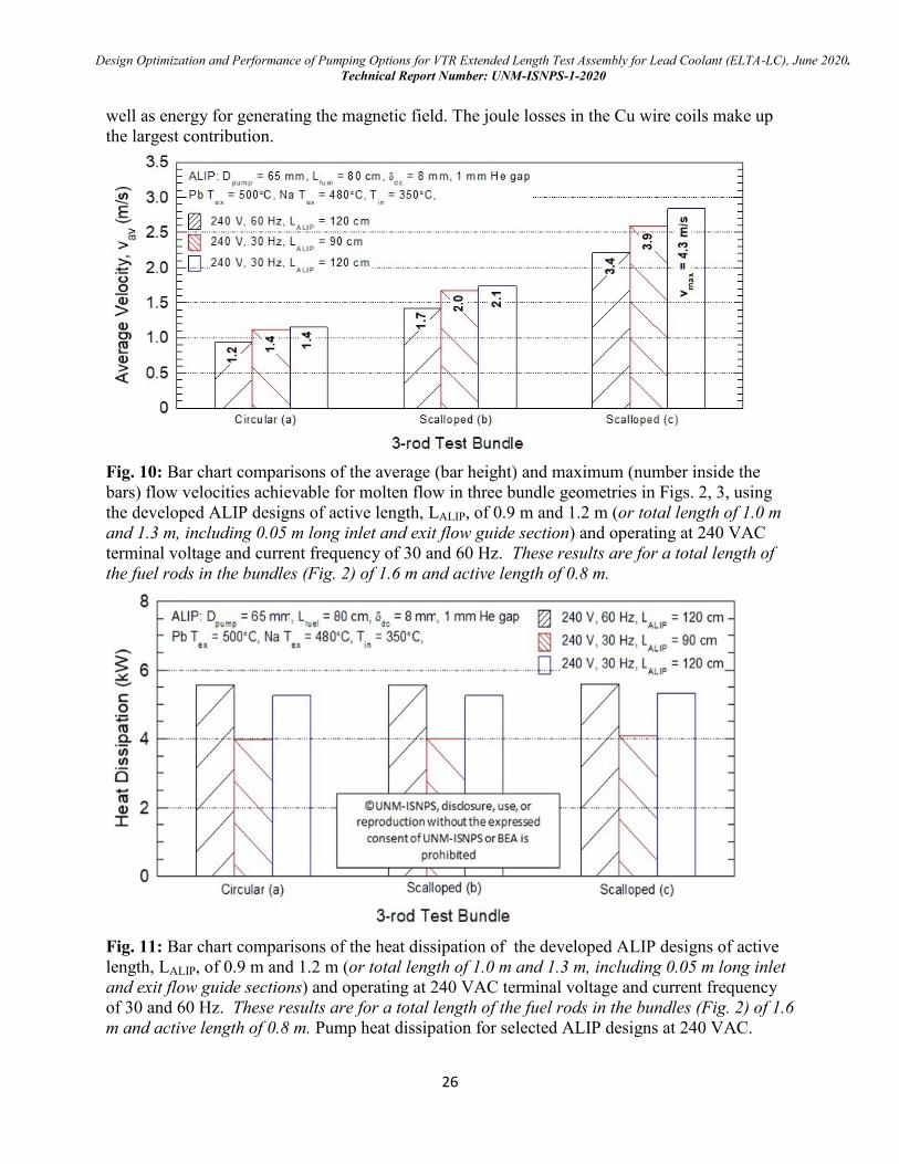
Fig. 10: Bar chart comparisons of the average (bar height) and maximum (number inside the
bars) flow velocities achievable for molten flow in three bundle geometries in Figs. 2, 3, using
the developed ALIP designs of active length, LALIP, of 0.9 m and 1.2 m (or total length of 1.0 m
and 1.3 m, including 0.05 m long inlet and exit flow guide section) and operating at 240 VAC
terminal voltage and current frequency of 30 and 60 Hz. These results are for a total length of
the fuel rods in the bundles (Fig. 2) of 1.6 m and active length of 0.8 m.
Fig. 11: Bar chart comparisons of the heat dissipation of the developed ALIP designs of active
length, LALIP, of 0.9 m and 1.2 m (or total length of 1.0 m and 1.3 m, including 0.05 m long inlet
and exit flow guide sections) and operating at 240 VAC terminal voltage and current frequency
of 30 and 60 Hz. These results are for a total length of the fuel rods in the bundles (Fig. 2) of 1.6
m and active length of 0.8 m. Pump heat dissipation for selected ALIP designs at 240 VAC.

Design Optimization and Performance of Pumping Options for VTR Extended Length Test Assembly for Lead Coolant (ELTA-LC), June 2020.
Technical Report Number: UNM-ISNPS-1-2020
27
With organic insulated Cu coils, the dissipated heat due to joule losses in the Cu coils would
have to be actively removed using circulating gas or oil through the Cu wire coils. If ceramic
insulated Cu wires are employed, the full dissipated heat in the ALIP will be transferred to the
molten lead flow in the ELTA-CL. These issues will be the subject for future investigations and
design optimization of the ALIP design.
Design Optimization and Performance of Pumping Options for VTR Extended Length Test Assembly for Lead Coolant (ELTA-LC), June 2020.
Technical Report Number: UNM-ISNPS-1-2020
28
5. DC conduction EM Pump (EMP) design optimization and analyses
Excellent progress has been made on the design optimization and analyses of miniature,
submerged DC electromagnetic pump (EMP) for use in the ELTA-CL. This effort focused on
performing parametric analyses for design optimization, investigating materials for the
permanent magnets and the pump structure. The developed EMP design would operate using low
voltage (< 2.0 VDC) electric current up to 1100 A. It also employs off-the-shelf permanent
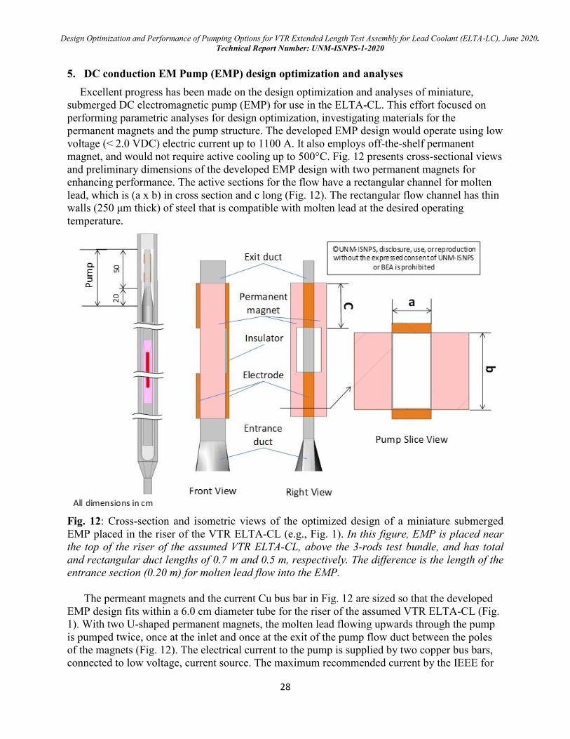
magnet, and would not require active cooling up to 500°C. Fig. 12 presents cross-sectional views
and preliminary dimensions of the developed EMP design with two permanent magnets for
enhancing performance. The active sections for the flow have a rectangular channel for molten
lead, which is (a x b) in cross section and c long (Fig. 12). The rectangular flow channel has thin
walls (250 μm thick) of steel that is compatible with molten lead at the desired operating
temperature.
Fig. 12: Cross-section and isometric views of the optimized design of a miniature submerged
EMP placed in the riser of the VTR ELTA-CL (e.g., Fig. 1). In this figure, EMP is placed near
the top of the riser of the assumed VTR ELTA-CL, above the 3-rods test bundle, and has total
and rectangular duct lengths of 0.7 m and 0.5 m, respectively. The difference is the length of the
entrance section (0.20 m) for molten lead flow into the EMP.
The permeant magnets and the current Cu bus bar in Fig. 12 are sized so that the developed
EMP design fits within a 6.0 cm diameter tube for the riser of the assumed VTR ELTA-CL (Fig.
1). With two U-shaped permanent magnets, the molten lead flowing upwards through the pump
is pumped twice, once at the inlet and once at the exit of the pump flow duct between the poles
of the magnets (Fig. 12). The electrical current to the pump is supplied by two copper bus bars,
connected to low voltage, current source. The maximum recommended current by the IEEE for

Design Optimization and Performance of Pumping Options for VTR Extended Length Test Assembly for Lead Coolant (ELTA-LC), June 2020.
Technical Report Number: UNM-ISNPS-1-2020
29
reducing joule losses depends on the cross section area of the Cu bus bar. The recommended
current density for copper bus bar is ≤ 2.8 A/mm2, which is consistent with current industrial
standards. These standards are followed in the performed development and design optimization
of the EMP for the VTR ELTA-CL (Fig. 1). As shown in Fig. 10, the EMP is placed near the top
of the riser for the VTR ELTA-CL, above the 3-rods test bundle, and has total and rectangular
duct lengths of 0.7 m and 0.5 m, respectively. The difference is the length of entrance section
(0.2 m) for the molten flow into the EMP.
Two materials are investigated for the permanent magnets in the developed EMP, namely:
ALNICO 5 and Hiperco 27, which have both been previously used or investigated for EMP
designs in high temperature nuclear applications (Davis et al., 1970; El-Genk, Buksa, Seo, 1987).
For the ALNICO 5 permanent magnet with a curie point of ~ 800oC.
It had been used in the
submerged Auxiliary Pump for circulating liquid Na in the EBR-II test reactor (Davis et al.,
1970). The Hiperco 27 permanent magnet had been considered for the EMPs for circulating
liquid Lithium in the primary and secondary loop of the SP-100 space reactor power system (El-
Genk, Buksa, Seo, 1987). The Hyperco 27 has a higher curie point of ~ 925°C and lower
resistance to demagnetizing (0.17 kA/m) than ALNICO 5. Thus, using Hyperco 27 magnets
would provide a greater margin to the Curie point when used at temperatures in excess of 500oC
in the VTR ELTA-CL.
Fig. 13: Calculated magnetic field lines distribution at the upper poles of the developed EMP
with dual ALNICO 5 magnets for the VTR ELTA-CL. The width, b, of the molten lead flow
channel in this figure is 10 mm.
On the other hand, ALNICO 5 produces a stronger magnetic field than Hiperco 27, which
supports high current operation at temperatures in excess of 500oC due to its greater resistance to
demagnetizing with increased temperature. The maximum temperature for reversible operation
of the ALNICO 5 permanent magnet is 525 °C. At this temperature the magnetic field strength is
Design Optimization and Performance of Pumping Options for VTR Extended Length Test Assembly for Lead Coolant (ELTA-LC), June 2020.
Technical Report Number: UNM-ISNPS-1-2020
30
93% of its value at 20°C. At 700°C, the magnetic field strength would only be 77% of its value
at 20 °C. Therefore, ALNICO 5 magnets are selected for use in the currently developed EMP
design for the VTR ELTA-CL (Fig. 12) operating at molten lead exit temperature of 500oC. For
higher temperatures, Hypreco 27 would be the appropriate choice, but would require
redesigning the EMP. Investigating this issue is planned as a part of future work.
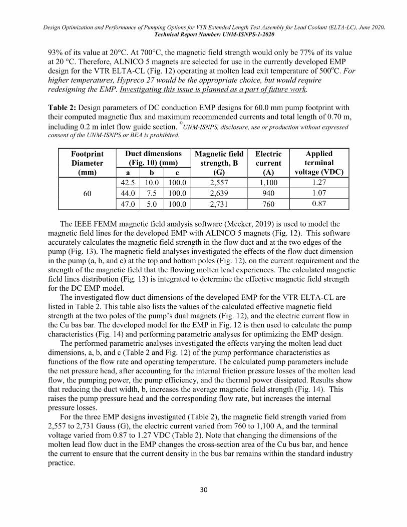
Table 2: Design parameters of DC conduction EMP designs for 60.0 mm pump footprint with
their computed magnetic flux and maximum recommended currents and total length of 0.70 m,
including 0.2 m inlet flow guide section. ©
UNM-ISNPS, disclosure, use or production without expressed
consent of the UNM-ISNPS or BEA is prohibited.
Footprint
Diameter
(mm)
Duct dimensions
(Fig. 10) (mm) Magnetic field
strength, B
(G)
Electric
current
(A)
Applied
terminal
voltage (VDC) a b c
60
42.5 10.0 100.0 2,557 1,100 1.27
44.0 7.5 100.0 2,639 940 1.07
47.0 5.0 100.0 2,731 760 0.87
The IEEE FEMM magnetic field analysis software (Meeker, 2019) is used to model the
magnetic field lines for the developed EMP with ALINCO 5 magnets (Fig. 12). This software
accurately calculates the magnetic field strength in the flow duct and at the two edges of the
pump (Fig. 13). The magnetic field analyses investigated the effects of the flow duct dimension
in the pump (a, b, and c) at the top and bottom poles (Fig. 12), on the current requirement and the
strength of the magnetic field that the flowing molten lead experiences. The calculated magnetic
field lines distribution (Fig. 13) is integrated to determine the effective magnetic field strength
for the DC EMP model.
The investigated flow duct dimensions of the developed EMP for the VTR ELTA-CL are
listed in Table 2. This table also lists the values of the calculated effective magnetic field
strength at the two poles of the pump’s dual magnets (Fig. 12), and the electric current flow in
the Cu bas bar. The developed model for the EMP in Fig. 12 is then used to calculate the pump
characteristics (Fig. 14) and performing parametric analyses for optimizing the EMP design.
The performed parametric analyses investigated the effects varying the molten lead duct
dimensions, a, b, and c (Table 2 and Fig. 12) of the pump performance characteristics as
functions of the flow rate and operating temperature. The calculated pump parameters include
the net pressure head, after accounting for the internal friction pressure losses of the molten lead
flow, the pumping power, the pump efficiency, and the thermal power dissipated. Results show
that reducing the duct width, b, increases the average magnetic field strength (Fig. 14). This
raises the pump pressure head and the corresponding flow rate, but increases the internal
pressure losses.
For the three EMP designs investigated (Table 2), the magnetic field strength varied from
2,557 to 2,731 Gauss (G), the electric current varied from 760 to 1,100 A, and the terminal
voltage varied from 0.87 to 1.27 VDC (Table 2). Note that changing the dimensions of the
molten lead flow duct in the EMP changes the cross-section area of the Cu bus bar, and hence
the current to ensure that the current density in the bus bar remains within the standard industry
practice.
Design Optimization and Performance of Pumping Options for VTR Extended Length Test Assembly for Lead Coolant (ELTA-LC), June 2020.
Technical Report Number: UNM-ISNPS-1-2020
31
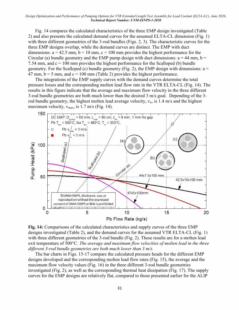
Fig. 14 compares the calculated characteristics of the three EMP design investigated (Table
2) and also presents the calculated demand curves for the assumed ELTA-CL dimension (Fig. 1)
with three different geometries of the 3-rod bundles (Figs. 2, 3). The characteristic curves for the
three EMP designs overlap, while the demand curves are distinct. The EMP with duct
dimensions: a = 42.5 mm, b = 10 mm, c = 100 mm provides the highest performance for the
Circular (a) bundle geometry and the EMP pump design with duct dimensions: a = 44 mm, b =
7.54 mm, and c = 100 mm provides the highest performance for the Scalloped (b) bundle
geometry. For the Scalloped (c) bundle geometry (Fig. 2), the EMP design with dimensions: a =
47 mm, b = 5 mm, and c = 100 mm (Table 2) provides the highest performance.
The integrations of the EMP supply curves with the demand curves determine the total
pressure losses and the corresponding molten lead flow rate in the VTR ELTA-CL (Fig. 14). The
results in this figure indicate that the average and maximum flow velocity in the three different
3-rod bundle geometries are both much lower than the desired 3 m/s goal. Depending of the 3-
rod bundle geometry, the highest molten lead average velocity, vav is 1.4 m/s and the highest
maximum velocity, vmax, is 1.7 m/s (Fig. 14).
Fig. 14: Comparisons of the calculated characteristics and supply curves of the three EMP
designs investigated (Table 2), and the demand curves for the assumed VTR ELTA-CL (Fig. 1)
with three different geometries of the 3-rod bundle (Fig. 2). These results are for a molten lead
exit temperature of 500°C. The average and maximum flow velocities of molten lead in the three
different 3-rod bundle geometries are both much lower than 3 m/s.
The bar charts in Figs. 15-17 compare the calculated pressure heads for the different EMP
designs developed and the corresponding molten lead flow rates (Fig. 15), the average and the
maximum flow velocity values (Fig. 16) in the three different 3-rod bundle geometries
investigated (Fig. 2), as well as the corresponding thermal heat dissipation (Fig. 17). The supply
curves for the EMP designs are relatively flat, compared to those presented earlier for the ALIP
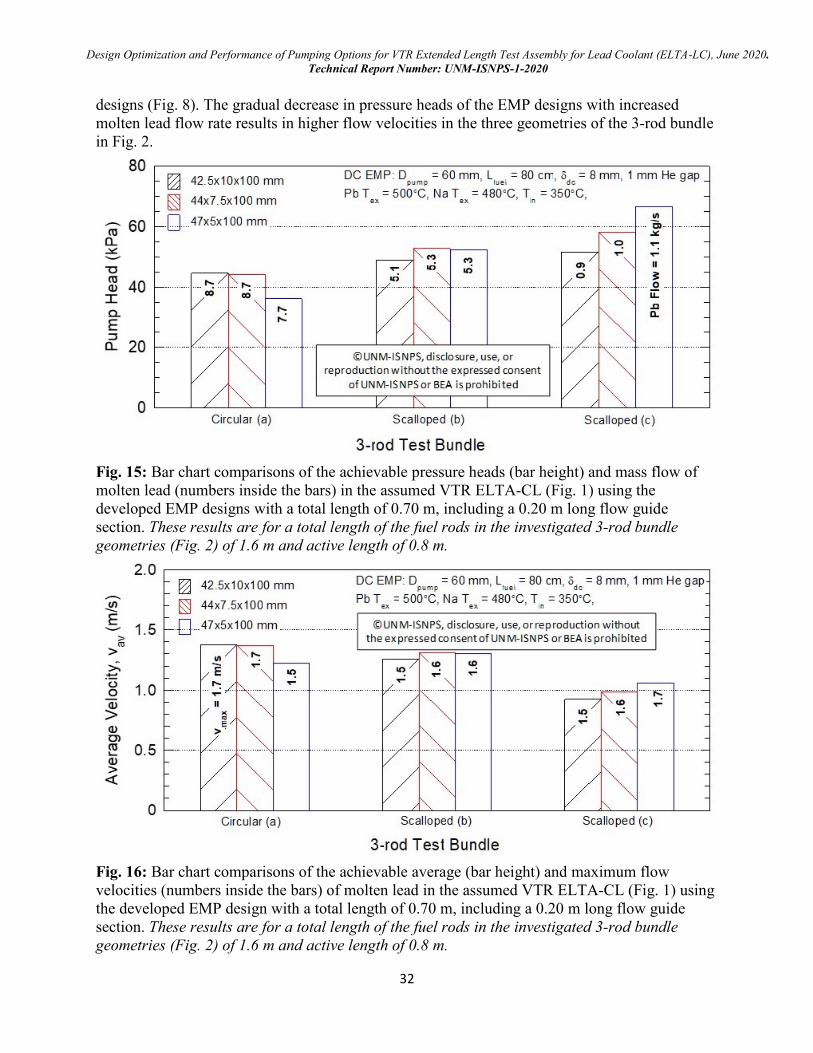
Design Optimization and Performance of Pumping Options for VTR Extended Length Test Assembly for Lead Coolant (ELTA-LC), June 2020.
Technical Report Number: UNM-ISNPS-1-2020
32
designs (Fig. 8). The gradual decrease in pressure heads of the EMP designs with increased
molten lead flow rate results in higher flow velocities in the three geometries of the 3-rod bundle
in Fig. 2.
Fig. 15: Bar chart comparisons of the achievable pressure heads (bar height) and mass flow of
molten lead (numbers inside the bars) in the assumed VTR ELTA-CL (Fig. 1) using the
developed EMP designs with a total length of 0.70 m, including a 0.20 m long flow guide
section. These results are for a total length of the fuel rods in the investigated 3-rod bundle
geometries (Fig. 2) of 1.6 m and active length of 0.8 m.
Fig. 16: Bar chart comparisons of the achievable average (bar height) and maximum flow
velocities (numbers inside the bars) of molten lead in the assumed VTR ELTA-CL (Fig. 1) using
the developed EMP design with a total length of 0.70 m, including a 0.20 m long flow guide
section. These results are for a total length of the fuel rods in the investigated 3-rod bundle
geometries (Fig. 2) of 1.6 m and active length of 0.8 m.
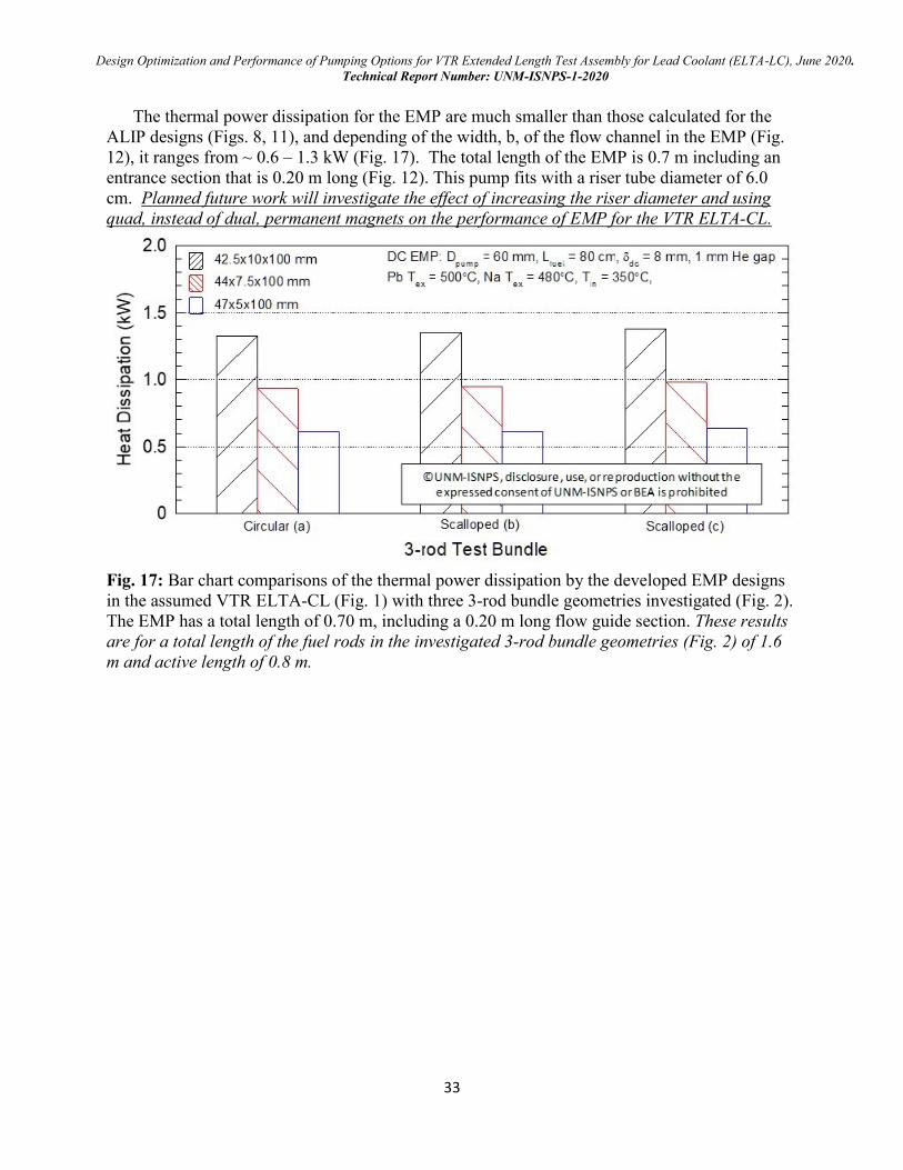
Design Optimization and Performance of Pumping Options for VTR Extended Length Test Assembly for Lead Coolant (ELTA-LC), June 2020.
Technical Report Number: UNM-ISNPS-1-2020
33
The thermal power dissipation for the EMP are much smaller than those calculated for the
ALIP designs (Figs. 8, 11), and depending of the width, b, of the flow channel in the EMP (Fig.
12), it ranges from ~ 0.6 – 1.3 kW (Fig. 17). The total length of the EMP is 0.7 m including an
entrance section that is 0.20 m long (Fig. 12). This pump fits with a riser tube diameter of 6.0
cm. Planned future work will investigate the effect of increasing the riser diameter and using
quad, instead of dual, permanent magnets on the performance of EMP for the VTR ELTA-CL.
Fig. 17: Bar chart comparisons of the thermal power dissipation by the developed EMP designs
in the assumed VTR ELTA-CL (Fig. 1) with three 3-rod bundle geometries investigated (Fig. 2).
The EMP has a total length of 0.70 m, including a 0.20 m long flow guide section. These results
are for a total length of the fuel rods in the investigated 3-rod bundle geometries (Fig. 2) of 1.6
m and active length of 0.8 m.
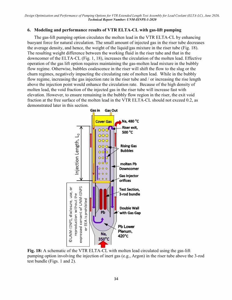
Design Optimization and Performance of Pumping Options for VTR Extended Length Test Assembly for Lead Coolant (ELTA-LC), June 2020.
Technical Report Number: UNM-ISNPS-1-2020
34
6. Modeling and performance results of VTR ELTA-CL with gas-lift pumping
The gas-lift pumping option circulates the molten lead in the VTR ELTA-CL by enhancing
buoyant force for natural circulation. The small amount of injected gas in the riser tube decreases
the average density, and hence, the weight of the liquid/gas mixture in the riser tube (Fig. 18).
The resulting weight difference between the working fluid in the riser tube and that in the
downcomer of the ELTA-CL (Fig. 1, 18), increases the circulation of the molten lead. Effective
operation of the gas lift option requires maintaining the gas-molten lead mixture in the bubbly
flow regime. Otherwise, bubbles coalescence in the riser will shift the flow to the slug or the
churn regimes, negatively impacting the circulating rate of molten lead. While in the bubbly
flow regime, increasing the gas injection rate in the riser tube and / or increasing the rise length
above the injection point would enhance the circulation rate. Because of the high density of
molten lead, the void fraction of the injected gas in the riser tube will increase fast with
elevation. However, to ensure remaining in the bubbly flow region in the riser, the exit void
fraction at the free surface of the molten lead in the VTR ELTA-CL should not exceed 0.2, as
demonstrated later in this section.
Fig. 18: A schematic of the VTR ELTA-CL with molten lead circulated using the gas-lift
pumping option involving the injection of inert gas (e.g., Argon) in the riser tube above the 3-rod
test bundle (Figs. 1 and 2).
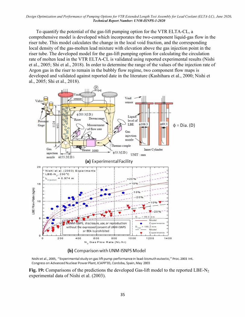
Design Optimization and Performance of Pumping Options for VTR Extended Length Test Assembly for Lead Coolant (ELTA-LC), June 2020.
Technical Report Number: UNM-ISNPS-1-2020
35
To quantify the potential of the gas-lift pumping option for the VTR ELTA-CL, a
comprehensive model is developed which incorporates the two-component liquid-gas flow in the
riser tube. This model calculates the change in the local void fraction, and the corresponding
local density of the gas-molten lead mixture with elevation above the gas injection point in the
riser tube. The developed model for the gas-lift pumping option for calculating the circulation
rate of molten lead in the VTR ELTA-CL is validated using reported experimental results (Nishi
et al., 2005; Shi et al., 2018). In order to determine the range of the values of the injection rate of
Argon gas in the riser to remain in the bubbly flow regime, two component flow maps is
developed and validated against reported date in the literature (Kashihara et al., 2000; Nishi et
al., 2005; Shi et al., 2018).
Fig. 19: Comparisons of the predictions the developed Gas-lift model to the reported LBE-N2
experimental data of Nishi et al. (2003).
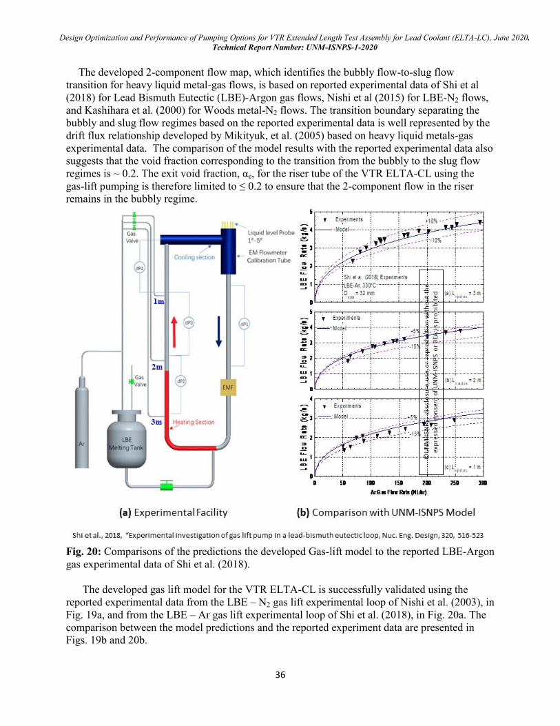
Design Optimization and Performance of Pumping Options for VTR Extended Length Test Assembly for Lead Coolant (ELTA-LC), June 2020.
Technical Report Number: UNM-ISNPS-1-2020
36
The developed 2-component flow map, which identifies the bubbly flow-to-slug flow
transition for heavy liquid metal-gas flows, is based on reported experimental data of Shi et al
(2018) for Lead Bismuth Eutectic (LBE)-Argon gas flows, Nishi et al (2015) for LBE-N2 flows,
and Kashihara et al. (2000) for Woods metal-N2 flows. The transition boundary separating the
bubbly and slug flow regimes based on the reported experimental data is well represented by the
drift flux relationship developed by Mikityuk, et al. (2005) based on heavy liquid metals-gas
experimental data. The comparison of the model results with the reported experimental data also
suggests that the void fraction corresponding to the transition from the bubbly to the slug flow
regimes is ~ 0.2. The exit void fraction, αe, for the riser tube of the VTR ELTA-CL using the
gas-lift pumping is therefore limited to ≤ 0.2 to ensure that the 2-component flow in the riser
remains in the bubbly regime.
Fig. 20: Comparisons of the predictions the developed Gas-lift model to the reported LBE-Argon
gas experimental data of Shi et al. (2018).
The developed gas lift model for the VTR ELTA-CL is successfully validated using the
reported experimental data from the LBE – N2 gas lift experimental loop of Nishi et al. (2003), in
Fig. 19a, and from the LBE – Ar gas lift experimental loop of Shi et al. (2018), in Fig. 20a. The
comparison between the model predictions and the reported experiment data are presented in
Figs. 19b and 20b.
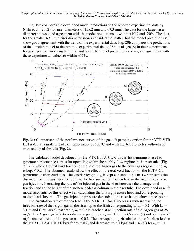
Design Optimization and Performance of Pumping Options for VTR Extended Length Test Assembly for Lead Coolant (ELTA-LC), June 2020.
Technical Report Number: UNM-ISNPS-1-2020
37
Fig. 19b compares the developed model predictions to the reported experimental data by
Nishi et al. (2002) for riser diameters of 155.2 mm and 69.3 mm. The data for the larger riser
diameter shows good agreement with the model predictions to within +10% and -20%. The data
for the smaller 69.3 mm riser diameter shows considerable scatter, but the model predictions still
show good agreement with the trend of the experimental data. Fig. 20b compares the predictions
of the develop model to the reported experimental data of Shi et al. (2018) in their experiments
for gas injection riser length of 1, 2, and 3 m. The model predictions show good agreement with
these experimental values to within ±15%.
Fig. 21: Comparison of the performance curves of the gas-lift pumping option for the VTR VTR
ELTA-CL at a molten lead exit temperature of 500°C and with the 3-rod bundles without and
with scalloped shrouds (Fig. 2).
The validated model developed for the VTR ELTA-CL with gas-lift pumping is used to
generate performance curves for operating within the bubbly flow regime in the riser tube (Figs.
21, 22), where the exit void fraction of the injected Argon gas to the cover gas region in the, αe,
is kept ≤ 0.2. The obtained results show the effect of the exit void fraction on the ELTA-CL
performance characteristics. The gas rise length, Lo, is kept constant at 3.1 m. L0 represents the
distance from the gas injection point to the free surface on molten lead in the riser tube, at zero
gas injection. Increasing the rate of the injected gas in the riser increases the average void
fraction and so the height of the molten lead-gas column in the riser tube. The developed gas-lift
model accounts for this effect when calculating the driving pressure head and corresponding
molten lead flow rate. The gas injection pressure depends of the riser height above inject point.
The circulation rate of molten lead in the VTR ELTA-CL increases with increasing the
injection rate of the Argon gas in the riser, up to the limit corresponding to αe = 0.2. With Lo =
3.1 m and Circular (a) test article, αe = 0.2 is reached at an injection rate of the Argon gas of 251
mg/s. The Argon gas injection rate corresponding to αe = 0.1 for the Circular (a) rod bundle is 96
mg/s, and reduced to 41 mg/s for αe = 0.05. The corresponding circulation rate of molten lead in
the VTR ELTA-CL is 8.0 kg/s for αe = 0.2, and decreases to 5.1 kg/s and 3.4 kg/s for αe = 0.1
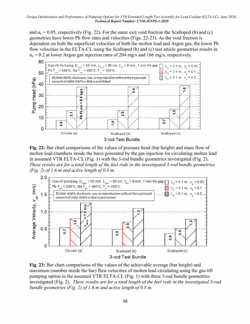
Design Optimization and Performance of Pumping Options for VTR Extended Length Test Assembly for Lead Coolant (ELTA-LC), June 2020.
Technical Report Number: UNM-ISNPS-1-2020
38
and αe = 0.05, respectively (Fig. 22). For the same exit void fraction the Scalloped (b) and (c)
geometries have lower Pb flow rates and velocities (Figs. 22-23). As the void fraction is
dependent on both the superficial velocities of both the molten lead and Argon gas, the lower Pb
flow velocities in the ELTA-CL using the Scalloped (b) and (c) test article geometries results in
αe = 0.2 at lower Argon gas injection rates of 204 mg/s and 166 mg/s, respectively.
Fig. 22: Bar chart comparisons of the values of pressure head (bar height) and mass flow of
molten lead (numbers inside the bars) generated by the gas injection for circulating molten lead
in assumed VTR ELTA-CL (Fig. 1) with the 3-rod bundle geometries investigated (Fig. 2).
These results are for a total length of the fuel rods in the investigated 3-rod bundle geometries
(Fig. 2) of 1.6 m and active length of 0.8 m.
Fig. 23: Bar chart comparisons of the values of the achievable average (bar height) and
maximum (number inside the bar) flow velocities of molten lead circulating using the gas-lift
pumping option in the assumed VTR ELTA-CL (Fig. 1) with three 3-rod bundle geometries
investigated (Fig. 2). These results are for a total length of the fuel rods in the investigated 3-rod
bundle geometries (Fig. 2) of 1.6 m and active length of 0.8 m.
Design Optimization and Performance of Pumping Options for VTR Extended Length Test Assembly for Lead Coolant (ELTA-LC), June 2020.
Technical Report Number: UNM-ISNPS-1-2020
39
It is noteworthy that there is no thermal power dissipation associated with circulating the
molten lead in the VTR ELTA-CL using the gas-lift pumping option. However, a long gas line is
required to penetrate the VTR boundary and reach the VTR ELTA-CL. The developed driving
pressure head using the gas-lift pumping option, which slightly depends on the circulation rate of
molten lead in the VTR ELTA-CL, is nearly the same in the ELTA-CL with any of three, 3-rod
bundle geometries investigated (Fig. 2). However, the highest molten lead flow velocities are
achieved for the Circular (a) bundle geometry. For Lo = 3.1 m, the gas-lift pumping option can
result in a molten lead average velocity, Vav, of 1.3 m/s for the Circular (a) bundle geometry, 1.1
m/s for the Scalloped (b) bundle geometry , and 0.8 m/s for the more restrictive Scalloped (c)
bundle geometry. The corresponding maximum flow velocities in these bundle geometries are
1.5, 1.3, and 1.3 m/s, respectively.
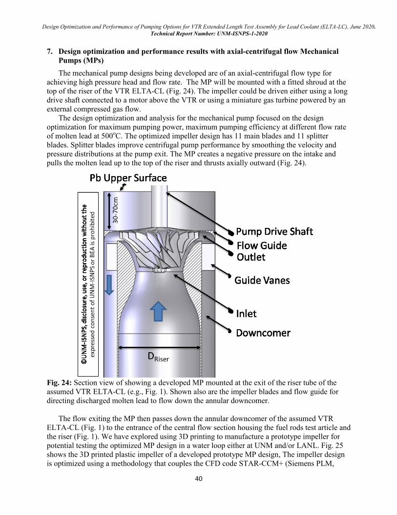
Design Optimization and Performance of Pumping Options for VTR Extended Length Test Assembly for Lead Coolant (ELTA-LC), June 2020.
Technical Report Number: UNM-ISNPS-1-2020
40
7. Design optimization and performance results with axial-centrifugal flow Mechanical
Pumps (MPs)
The mechanical pump designs being developed are of an axial-centrifugal flow type for
achieving high pressure head and flow rate. The MP will be mounted with a fitted shroud at the
top of the riser of the VTR ELTA-CL (Fig. 24). The impeller could be driven either using a long
drive shaft connected to a motor above the VTR or using a miniature gas turbine powered by an
external compressed gas flow.
The design optimization and analysis for the mechanical pump focused on the design
optimization for maximum pumping power, maximum pumping efficiency at different flow rate
of molten lead at 500oC. The optimized impeller design has 11 main blades and 11 splitter
blades. Splitter blades improve centrifugal pump performance by smoothing the velocity and
pressure distributions at the pump exit. The MP creates a negative pressure on the intake and
pulls the molten lead up to the top of the riser and thrusts axially outward (Fig. 24).
Fig. 24: Section view of showing a developed MP mounted at the exit of the riser tube of the
assumed VTR ELTA-CL (e.g., Fig. 1). Shown also are the impeller blades and flow guide for
directing discharged molten lead to flow down the annular downcomer.
The flow exiting the MP then passes down the annular downcomer of the assumed VTR
ELTA-CL (Fig. 1) to the entrance of the central flow section housing the fuel rods test article and
the riser (Fig. 1). We have explored using 3D printing to manufacture a prototype impeller for
potential testing the optimized MP design in a water loop either at UNM and/or LANL. Fig. 25
shows the 3D printed plastic impeller of a developed prototype MP design, The impeller design
is optimized using a methodology that couples the CFD code STAR-CCM+ (Siemens PLM,
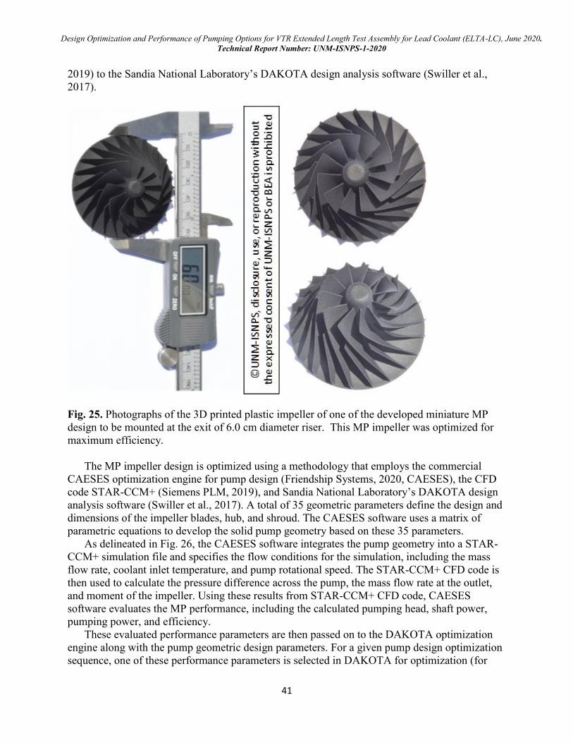
Design Optimization and Performance of Pumping Options for VTR Extended Length Test Assembly for Lead Coolant (ELTA-LC), June 2020.
Technical Report Number: UNM-ISNPS-1-2020
41
2019) to the Sandia National Laboratory’s DAKOTA design analysis software (Swiller et al.,
2017).
Fig. 25. Photographs of the 3D printed plastic impeller of one of the developed miniature MP
design to be mounted at the exit of 6.0 cm diameter riser. This MP impeller was optimized for
maximum efficiency.
The MP impeller design is optimized using a methodology that employs the commercial
CAESES optimization engine for pump design (Friendship Systems, 2020, CAESES), the CFD
code STAR-CCM+ (Siemens PLM, 2019), and Sandia National Laboratory’s DAKOTA design
analysis software (Swiller et al., 2017). A total of 35 geometric parameters define the design and
dimensions of the impeller blades, hub, and shroud. The CAESES software uses a matrix of
parametric equations to develop the solid pump geometry based on these 35 parameters.
As delineated in Fig. 26, the CAESES software integrates the pump geometry into a STAR-
CCM+ simulation file and specifies the flow conditions for the simulation, including the mass
flow rate, coolant inlet temperature, and pump rotational speed. The STAR-CCM+ CFD code is
then used to calculate the pressure difference across the pump, the mass flow rate at the outlet,
and moment of the impeller. Using these results from STAR-CCM+ CFD code, CAESES
software evaluates the MP performance, including the calculated pumping head, shaft power,
pumping power, and efficiency.
These evaluated performance parameters are then passed on to the DAKOTA optimization
engine along with the pump geometric design parameters. For a given pump design optimization
sequence, one of these performance parameters is selected in DAKOTA for optimization (for
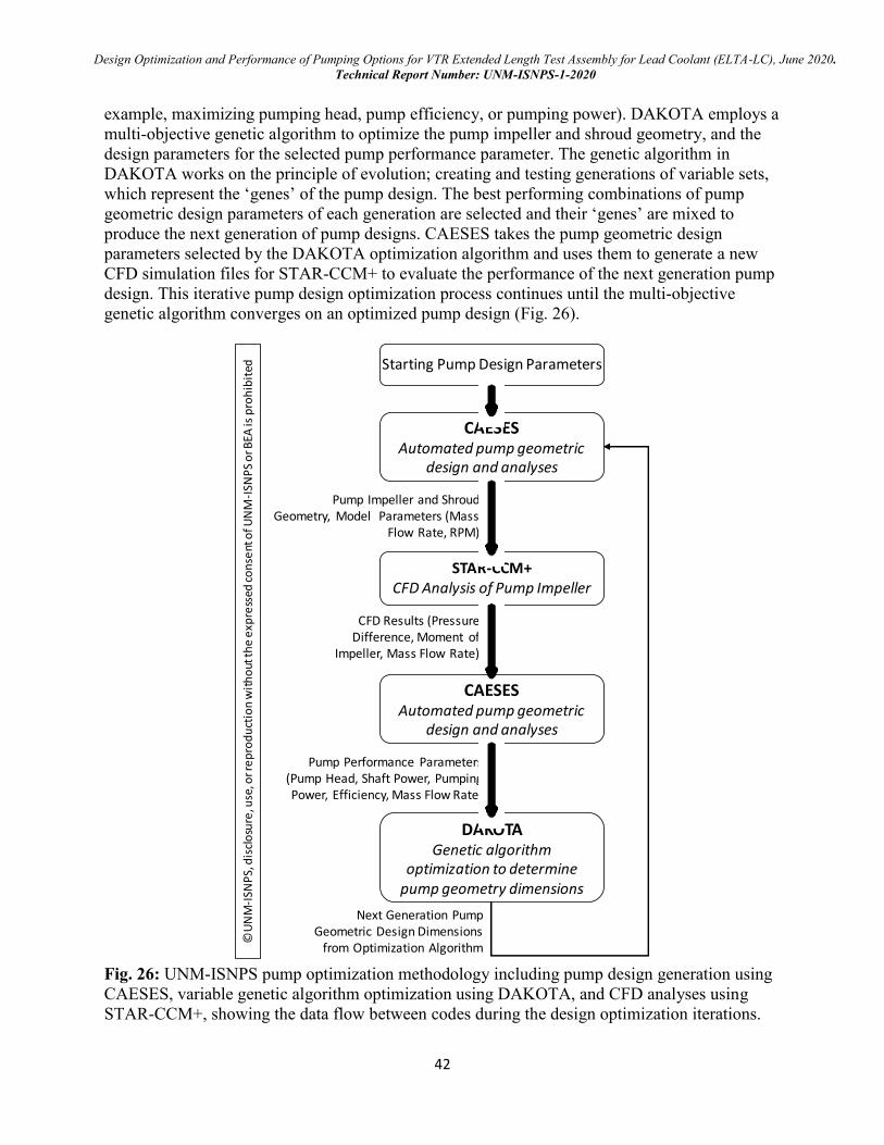
Design Optimization and Performance of Pumping Options for VTR Extended Length Test Assembly for Lead Coolant (ELTA-LC), June 2020.
Technical Report Number: UNM-ISNPS-1-2020
42
example, maximizing pumping head, pump efficiency, or pumping power). DAKOTA employs a
multi-objective genetic algorithm to optimize the pump impeller and shroud geometry, and the
design parameters for the selected pump performance parameter. The genetic algorithm in
DAKOTA works on the principle of evolution; creating and testing generations of variable sets,
which represent the ‘genes’ of the pump design. The best performing combinations of pump
geometric design parameters of each generation are selected and their ‘genes’ are mixed to
produce the next generation of pump designs. CAESES takes the pump geometric design
parameters selected by the DAKOTA optimization algorithm and uses them to generate a new
CFD simulation files for STAR-CCM+ to evaluate the performance of the next generation pump
design. This iterative pump design optimization process continues until the multi-objective
genetic algorithm converges on an optimized pump design (Fig. 26).
Fig. 26: UNM-ISNPS pump optimization methodology including pump design generation using
CAESES, variable genetic algorithm optimization using DAKOTA, and CFD analyses using
STAR-CCM+, showing the data flow between codes during the design optimization iterations.
CAESESAutomated pump geometric
design and analyses
Starting Pump Design Parameters
DAKOTAGenetic algorithm
optimization to determine pump geometry dimensions
STAR-CCM+CFD Analysis of Pump Impeller
Pump Performance Parameters (Pump Head, Shaft Power, Pumping Power, Efficiency, Mass Flow Rate)
Next Generation Pump Geometric Design Dimensions
from Optimization Algorithm
Pump Impeller and Shroud Geometry, Model Parameters (Mass
Flow Rate, RPM)
CFD Results (Pressure Difference, Moment of
Impeller, Mass Flow Rate)
©U
NM
-ISN
PS,
dis
clo
sure
, use
, or r
ep
rod
uct
ion
wit
ho
ut th
e e
xpre
ssed
co
nse
nt o
f UN
M-I
SNP
S o
r BEA
is p
roh
ibit
ed
CAESESAutomated pump geometric
design and analyses
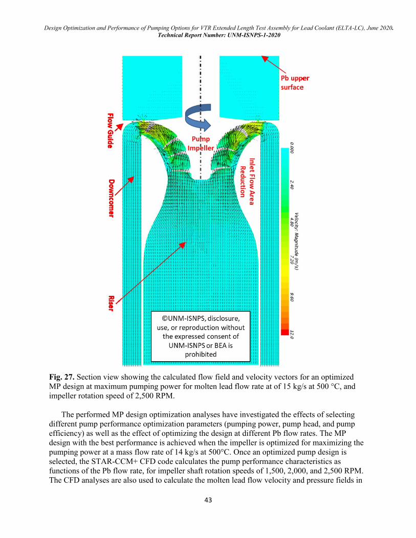
Design Optimization and Performance of Pumping Options for VTR Extended Length Test Assembly for Lead Coolant (ELTA-LC), June 2020.
Technical Report Number: UNM-ISNPS-1-2020
43
Fig. 27. Section view showing the calculated flow field and velocity vectors for an optimized
MP design at maximum pumping power for molten lead flow rate at of 15 kg/s at 500 °C, and
impeller rotation speed of 2,500 RPM.
The performed MP design optimization analyses have investigated the effects of selecting
different pump performance optimization parameters (pumping power, pump head, and pump
efficiency) as well as the effect of optimizing the design at different Pb flow rates. The MP
design with the best performance is achieved when the impeller is optimized for maximizing the
pumping power at a mass flow rate of 14 kg/s at 500°C. Once an optimized pump design is
selected, the STAR-CCM+ CFD code calculates the pump performance characteristics as
functions of the Pb flow rate, for impeller shaft rotation speeds of 1,500, 2,000, and 2,500 RPM.
The CFD analyses are also used to calculate the molten lead flow velocity and pressure fields in
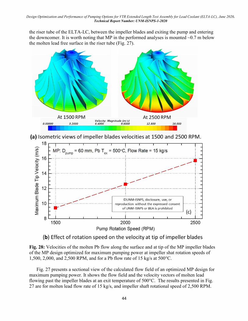
Design Optimization and Performance of Pumping Options for VTR Extended Length Test Assembly for Lead Coolant (ELTA-LC), June 2020.
Technical Report Number: UNM-ISNPS-1-2020
44
the riser tube of the ELTA-LC, between the impeller blades and exiting the pump and entering
the downcomer. It is worth noting that MP in the performed analyses is mounted ~0.7 m below
the molten lead free surface in the riser tube (Fig. 27).
Fig. 28: Velocities of the molten Pb flow along the surface and at tip of the MP impeller blades
of the MP design optimized for maximum pumping power at impeller shat rotation speeds of
1,500, 2,000, and 2,500 RPM, and for a Pb flow rate of 15 kg/s at 500°C.
Fig. 27 presents a sectional view of the calculated flow field of an optimized MP design for
maximum pumping power. It shows the flow field and the velocity vectors of molten lead
flowing past the impeller blades at an exit temperature of 500°C. The results presented in Fig.
27 are for molten lead flow rate of 15 kg/s, and impeller shaft rotational speed of 2,500 RPM.
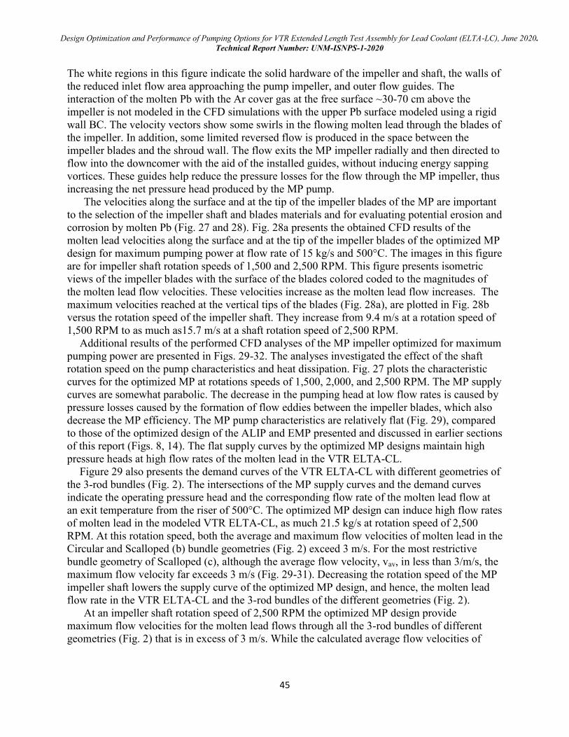
Design Optimization and Performance of Pumping Options for VTR Extended Length Test Assembly for Lead Coolant (ELTA-LC), June 2020.
Technical Report Number: UNM-ISNPS-1-2020
45
The white regions in this figure indicate the solid hardware of the impeller and shaft, the walls of
the reduced inlet flow area approaching the pump impeller, and outer flow guides. The
interaction of the molten Pb with the Ar cover gas at the free surface ~30-70 cm above the
impeller is not modeled in the CFD simulations with the upper Pb surface modeled using a rigid
wall BC. The velocity vectors show some swirls in the flowing molten lead through the blades of
the impeller. In addition, some limited reversed flow is produced in the space between the
impeller blades and the shroud wall. The flow exits the MP impeller radially and then directed to
flow into the downcomer with the aid of the installed guides, without inducing energy sapping
vortices. These guides help reduce the pressure losses for the flow through the MP impeller, thus
increasing the net pressure head produced by the MP pump.
The velocities along the surface and at the tip of the impeller blades of the MP are important
to the selection of the impeller shaft and blades materials and for evaluating potential erosion and
corrosion by molten Pb (Fig. 27 and 28). Fig. 28a presents the obtained CFD results of the
molten lead velocities along the surface and at the tip of the impeller blades of the optimized MP
design for maximum pumping power at flow rate of 15 kg/s and 500°C. The images in this figure
are for impeller shaft rotation speeds of 1,500 and 2,500 RPM. This figure presents isometric
views of the impeller blades with the surface of the blades colored coded to the magnitudes of
the molten lead flow velocities. These velocities increase as the molten lead flow increases. The
maximum velocities reached at the vertical tips of the blades (Fig. 28a), are plotted in Fig. 28b
versus the rotation speed of the impeller shaft. They increase from 9.4 m/s at a rotation speed of
1,500 RPM to as much as15.7 m/s at a shaft rotation speed of 2,500 RPM.
Additional results of the performed CFD analyses of the MP impeller optimized for maximum
pumping power are presented in Figs. 29-32. The analyses investigated the effect of the shaft
rotation speed on the pump characteristics and heat dissipation. Fig. 27 plots the characteristic
curves for the optimized MP at rotations speeds of 1,500, 2,000, and 2,500 RPM. The MP supply
curves are somewhat parabolic. The decrease in the pumping head at low flow rates is caused by
pressure losses caused by the formation of flow eddies between the impeller blades, which also
decrease the MP efficiency. The MP pump characteristics are relatively flat (Fig. 29), compared
to those of the optimized design of the ALIP and EMP presented and discussed in earlier sections
of this report (Figs. 8, 14). The flat supply curves by the optimized MP designs maintain high
pressure heads at high flow rates of the molten lead in the VTR ELTA-CL.
Figure 29 also presents the demand curves of the VTR ELTA-CL with different geometries of
the 3-rod bundles (Fig. 2). The intersections of the MP supply curves and the demand curves
indicate the operating pressure head and the corresponding flow rate of the molten lead flow at
an exit temperature from the riser of 500°C. The optimized MP design can induce high flow rates
of molten lead in the modeled VTR ELTA-CL, as much 21.5 kg/s at rotation speed of 2,500
RPM. At this rotation speed, both the average and maximum flow velocities of molten lead in the
Circular and Scalloped (b) bundle geometries (Fig. 2) exceed 3 m/s. For the most restrictive
bundle geometry of Scalloped (c), although the average flow velocity, vav, in less than 3/m/s, the
maximum flow velocity far exceeds 3 m/s (Fig. 29-31). Decreasing the rotation speed of the MP
impeller shaft lowers the supply curve of the optimized MP design, and hence, the molten lead
flow rate in the VTR ELTA-CL and the 3-rod bundles of the different geometries (Fig. 2).
At an impeller shaft rotation speed of 2,500 RPM the optimized MP design provide
maximum flow velocities for the molten lead flows through all the 3-rod bundles of different
geometries (Fig. 2) that is in excess of 3 m/s. While the calculated average flow velocities of
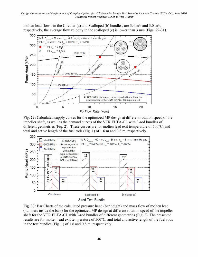
Design Optimization and Performance of Pumping Options for VTR Extended Length Test Assembly for Lead Coolant (ELTA-LC), June 2020.
Technical Report Number: UNM-ISNPS-1-2020
46
molten lead flow s in the Circular (a) and Scalloped (b) bundles, are 3.4 m/s and 3.0 m/s,
respectively, the average flow velocity in the scalloped (c) is lower than 3 m/s (Figs. 29-31).
Fig. 29: Calculated supply curves for the optimized MP design at different rotation speed of the
impeller shaft, as well as the demand curves of the VTR ELTA-CL with 3-rod bundles of
different geometries (Fig. 2). These curves are for molten lead exit temperature of 500°C, and
total and active length of the fuel rods (Fig. 1) of 1.6 m and 0.8 m, respectively.
Fig. 30: Bar Charts of the calculated pressure head (bar height) and mass flow of molten lead
(numbers inside the bars) for the optimized MP design at different rotation speed of the impeller
shaft for the VTR ELTA-CL with 3-rod bundles of different geometries (Fig. 2). The presented
results are for molten lead exit temperature of 500°C, and total and active length of the fuel rods
in the test bundles (Fig. 1) of 1.6 and 0.8 m, respectively.
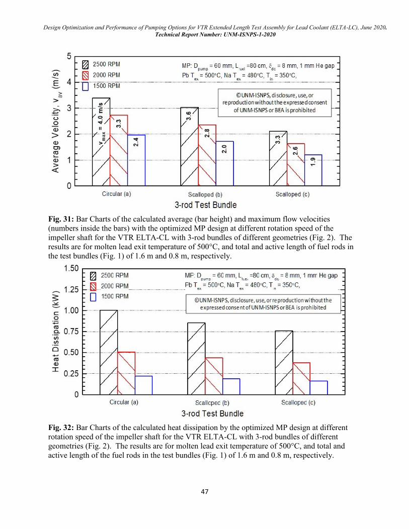
Design Optimization and Performance of Pumping Options for VTR Extended Length Test Assembly for Lead Coolant (ELTA-LC), June 2020.
Technical Report Number: UNM-ISNPS-1-2020
47
Fig. 31: Bar Charts of the calculated average (bar height) and maximum flow velocities
(numbers inside the bars) with the optimized MP design at different rotation speed of the
impeller shaft for the VTR ELTA-CL with 3-rod bundles of different geometries (Fig. 2). The
results are for molten lead exit temperature of 500°C, and total and active length of fuel rods in
the test bundles (Fig. 1) of 1.6 m and 0.8 m, respectively.
Fig. 32: Bar Charts of the calculated heat dissipation by the optimized MP design at different
rotation speed of the impeller shaft for the VTR ELTA-CL with 3-rod bundles of different
geometries (Fig. 2). The results are for molten lead exit temperature of 500°C, and total and
active length of the fuel rods in the test bundles (Fig. 1) of 1.6 m and 0.8 m, respectively.

Design Optimization and Performance of Pumping Options for VTR Extended Length Test Assembly for Lead Coolant (ELTA-LC), June 2020.
Technical Report Number: UNM-ISNPS-1-2020
48
Increasing the rotation speed raises the supply curves of the MP, but also increases the
dissipated thermal power. The dissipated thermal power ranges from 0.76 to 1 kW at 2,500 RPM
and from 0.16- to 0.22 kW at an impeller shaft rotation speed of 1,500 RPM (Fig. 32). The
presented preliminary results for the optimized MP design for maximum pumping power suggest
that this pumping option is capable of providing a wide range of flow rates and flow velocities of
the molten lead in the 3-rod test bundles, including average velocities in excess of 3 m/s.
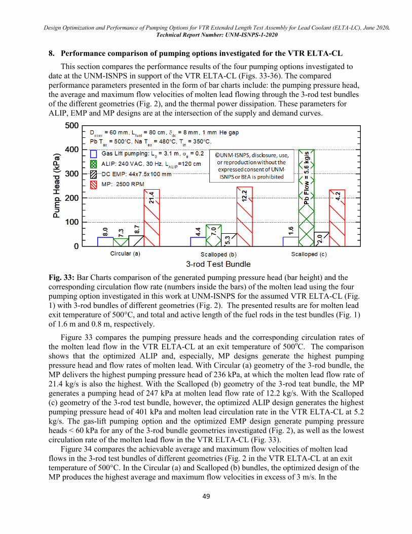
Design Optimization and Performance of Pumping Options for VTR Extended Length Test Assembly for Lead Coolant (ELTA-LC), June 2020.
Technical Report Number: UNM-ISNPS-1-2020
49
8. Performance comparison of pumping options investigated for the VTR ELTA-CL
This section compares the performance results of the four pumping options investigated to
date at the UNM-ISNPS in support of the VTR ELTA-CL (Figs. 33-36). The compared
performance parameters presented in the form of bar charts include: the pumping pressure head,
the average and maximum flow velocities of molten lead flowing through the 3-rod test bundles
of the different geometries (Fig. 2), and the thermal power dissipation. These parameters for
ALIP, EMP and MP designs are at the intersection of the supply and demand curves.
Fig. 33: Bar Charts comparison of the generated pumping pressure head (bar height) and the
corresponding circulation flow rate (numbers inside the bars) of the molten lead using the four
pumping option investigated in this work at UNM-ISNPS for the assumed VTR ELTA-CL (Fig.
1) with 3-rod bundles of different geometries (Fig. 2). The presented results are for molten lead
exit temperature of 500°C, and total and active length of the fuel rods in the test bundles (Fig. 1)
of 1.6 m and 0.8 m, respectively.
Figure 33 compares the pumping pressure heads and the corresponding circulation rates of
the molten lead flow in the VTR ELTA-CL at an exit temperature of 500oC. The comparison
shows that the optimized ALIP and, especially, MP designs generate the highest pumping
pressure head and flow rates of molten lead. With Circular (a) geometry of the 3-rod bundle, the
MP delivers the highest pumping pressure head of 236 kPa, at which the molten lead flow rate of
21.4 kg/s is also the highest. With the Scalloped (b) geometry of the 3-rod teat bundle, the MP
generates a pumping head of 247 kPa at molten lead flow rate of 12.2 kg/s. With the Scalloped
(c) geometry of the 3-rod test bundle, however, the optimized ALIP design generates the highest
pumping pressure head of 401 kPa and molten lead circulation rate in the VTR ELTA-CL at 5.2
kg/s. The gas-lift pumping option and the optimized EMP design generate pumping pressure
heads < 60 kPa for any of the 3-rod bundle geometries investigated (Fig. 2), as well as the lowest
circulation rate of the molten lead flow in the VTR ELTA-CL (Fig. 33).
Figure 34 compares the achievable average and maximum flow velocities of molten lead
flows in the 3-rod test bundles of different geometries (Fig. 2 in the VTR ELTA-CL at an exit
temperature of 500°C. In the Circular (a) and Scalloped (b) bundles, the optimized design of the
MP produces the highest average and maximum flow velocities in excess of 3 m/s. In the
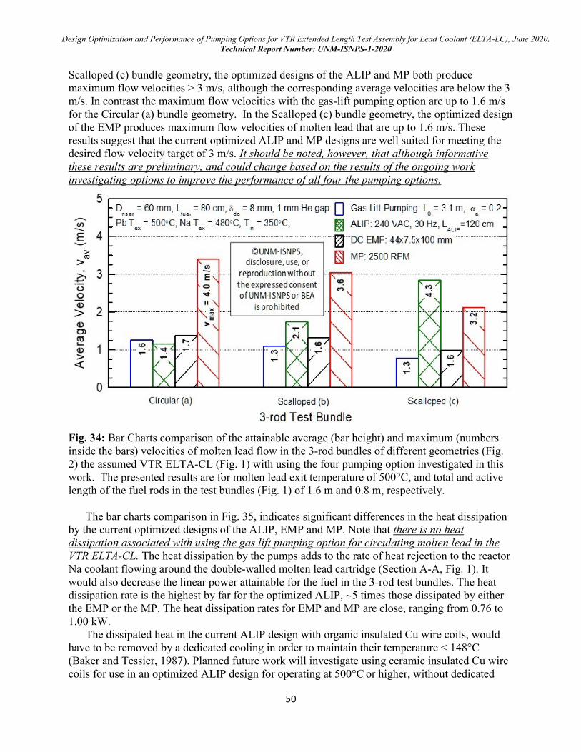
Design Optimization and Performance of Pumping Options for VTR Extended Length Test Assembly for Lead Coolant (ELTA-LC), June 2020.
Technical Report Number: UNM-ISNPS-1-2020
50
Scalloped (c) bundle geometry, the optimized designs of the ALIP and MP both produce
maximum flow velocities > 3 m/s, although the corresponding average velocities are below the 3
m/s. In contrast the maximum flow velocities with the gas-lift pumping option are up to 1.6 m/s
for the Circular (a) bundle geometry. In the Scalloped (c) bundle geometry, the optimized design
of the EMP produces maximum flow velocities of molten lead that are up to 1.6 m/s. These
results suggest that the current optimized ALIP and MP designs are well suited for meeting the
desired flow velocity target of 3 m/s. It should be noted, however, that although informative
these results are preliminary, and could change based on the results of the ongoing work
investigating options to improve the performance of all four the pumping options.
Fig. 34: Bar Charts comparison of the attainable average (bar height) and maximum (numbers
inside the bars) velocities of molten lead flow in the 3-rod bundles of different geometries (Fig.
2) the assumed VTR ELTA-CL (Fig. 1) with using the four pumping option investigated in this
work. The presented results are for molten lead exit temperature of 500°C, and total and active
length of the fuel rods in the test bundles (Fig. 1) of 1.6 m and 0.8 m, respectively.
The bar charts comparison in Fig. 35, indicates significant differences in the heat dissipation
by the current optimized designs of the ALIP, EMP and MP. Note that there is no heat
dissipation associated with using the gas lift pumping option for circulating molten lead in the
VTR ELTA-CL. The heat dissipation by the pumps adds to the rate of heat rejection to the reactor
Na coolant flowing around the double-walled molten lead cartridge (Section A-A, Fig. 1). It
would also decrease the linear power attainable for the fuel in the 3-rod test bundles. The heat
dissipation rate is the highest by far for the optimized ALIP, ~5 times those dissipated by either
the EMP or the MP. The heat dissipation rates for EMP and MP are close, ranging from 0.76 to
1.00 kW.
The dissipated heat in the current ALIP design with organic insulated Cu wire coils, would
have to be removed by a dedicated cooling in order to maintain their temperature < 148°C
(Baker and Tessier, 1987). Planned future work will investigate using ceramic insulated Cu wire
coils for use in an optimized ALIP design for operating at 500°C or higher, without dedicated
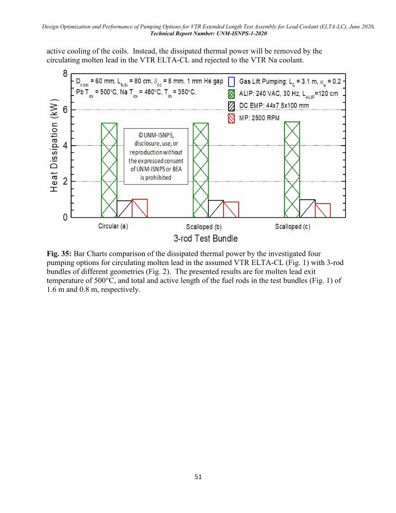
Design Optimization and Performance of Pumping Options for VTR Extended Length Test Assembly for Lead Coolant (ELTA-LC), June 2020.
Technical Report Number: UNM-ISNPS-1-2020
51
active cooling of the coils. Instead, the dissipated thermal power will be removed by the
circulating molten lead in the VTR ELTA-CL and rejected to the VTR Na coolant.
Fig. 35: Bar Charts comparison of the dissipated thermal power by the investigated four
pumping options for circulating molten lead in the assumed VTR ELTA-CL (Fig. 1) with 3-rod
bundles of different geometries (Fig. 2). The presented results are for molten lead exit
temperature of 500°C, and total and active length of the fuel rods in the test bundles (Fig. 1) of
1.6 m and 0.8 m, respectively.
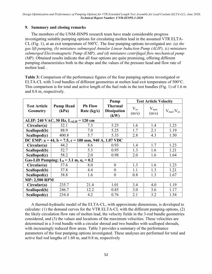
Design Optimization and Performance of Pumping Options for VTR Extended Length Test Assembly for Lead Coolant (ELTA-LC), June 2020.
Technical Report Number: UNM-ISNPS-1-2020
52
9. Summary and closing remarks
The members of the UNM-ISNPS research team have made considerable progress
investigating suitable pumping options for circulating molten lead in the assumed VTR ELTA-
CL (Fig. 1), at an exit temperature of 500oC. The four pumping options investigated are: (a) the
gas lift pumping, (b) miniature submerged Annular Linear Induction Pump (ALIP), (c) miniature
submerged Electromagnetic Pump (EMP), and (d) miniature centrifugal flow mechanical pump
(MP). Obtained results indicate that all four options are quite promising, offering different
pumping characteristics both in the shape and the values of the pressure head and flow rate of
molten lead. .
Table 3: Comparison of the performance figures of the four pumping options investigated or
ELTA-CL with 3-rod bundles of different geometries at molten lead exit temperature of 500°C.
This comparison is for total and active length of the fuel rods in the test bundles (Fig. 1) of 1.6 m
and 0.8 m, respectively.
Test Article
Geometry
Pump Head
(kPa)
Pb Flow
Rate (kg/s)
Pump
Thermal
Dissipation
(kW)
Test Article Velocity
Vav
(m/s)
Vmax
(m/s) Vmax/Vav
ALIP: 240 VAC, 30 Hz, LALIP = 120 cm
Circular(a) 32.1 7.3 5.25 1.6 1.4 1.23
Scalloped(b) 88.9 7.0 5.25 1.7 2.1 1.19
Scalloped(c) 400.8 5.7 5.33 2.8 4.3 1.50
DC EMP: a = 44, b = 7.5, c = 100 mm, 940 A, 1.07 VDC
Circular(a) 44.2 8.6 0.93 1.4 1.7 1.23
Scalloped(b) 52.7 5.3 0.95 1.3 1.6 1.21
Scalloped(c) 58.2 2.0 0.98 2.0 1.6 1.64
Gas-Lift Pumping: L0 = 3.1 m, αe = 0.2
Circular(a) 37.6 8.0 0 1.3 1.6 1.23
Scalloped(b) 37.8 4.4 0 1.1 1.3 1.21
Scalloped(c) 38.8 1.6 0 0.8 1.3 1.67
MP: 2,500 RPM
Circular(a) 235.7 21.4 1.01 3.4 4.0 1.19
Scalloped(b) 246.7 12.2 0.85 3.0 3.6 1.17
Scalloped(c) 234.4 4.2 0.76 2.1 3.2 1.54
A thermal-hydraulic model of the ELTA-CL, with approximate dimensions, is developed to
calculate: (1) the demand curves for the VTR ELTA-CL with the different pumping options, (2)
the likely circulation flow rate of molten lead, the velocity fields in the 3-rod bundle geometries
considered, and (3) the values and locations of the maximum velocities. These velocities are
determined in a 3-rod bundle with a circular shroud and two bundles with scalloped shrouds,
with increasingly reduced flow areas. Table 3 provides a summary of the performance
parameters of the four pumping options investigated. These analyses are performed for total and
active fuel rod lengths of 1.60 m, and 0.8 m, respectively
Design Optimization and Performance of Pumping Options for VTR Extended Length Test Assembly for Lead Coolant (ELTA-LC), June 2020.
Technical Report Number: UNM-ISNPS-1-2020
53
The gas-lift pumping option enhances circulation of molten lead through the assumed VTR
ELTA-CL by injecting argon gas at a very low rate in the riser near the exit from the 3-rods test
bundle. For this option, the performance depends on the average void fraction of the gas-molten
lead mixture in the riser, the height of the rise, and, to a lesser extent, the inner diameter of the
riser tube. A key to ensuring effectiveness of this option is to: (a) avoid or limit the coalescence
of the rising gas bubbles in the riser to the free surface in the VTR ELTA-CL, and (b) limit the
exit void fraction of the injected gas in the rise to < 0.2.
Results of conducted experiments in Japan and China successfully validated the developed
model of the gas-lift pumping option as well as the developed two-phase flow map for the gas-
molten lead mixture in the riser. This map helps ensures operating in the bubbly flow regime.
The gas-lift pumping option is the simplest of the four options investigated in this research and
would work at higher molten lead temperatures as it does not employ engineered features or
components other than a gas nozzle. However, a long gas line would be required to penetrate the
VTR head and reach the VTR ELTA-CL.
The optimized miniature ALIP designs, with 1.0 mm thick metal casing, fits in a 6.5 cm
diameter riser tube and currently are 1.0 -1.3 m long, including 0.05 m inlet and exit flow guide
sections. Decreasing the riser tube diameter decreases the width of the flow annulus in the pump,
below the current value of ~ 2 mm. A smaller channel width is undesirable in order to avoid
potential blockage of the flow annulus with dissolved impurities and / or frozen lead. Therefore,
increasing the riser tube diameter is likely to enhance the performance and reliability the ALIP
designs. Furthermore, to enhance the ALIP characteristics, the Cu coils need to be of sufficient
length, which favors either increasing the riser tube diameter beyond that currently used (6.5 cm)
or increasing the ALIP total length.
The analyses of the optimized ALIP designs investigated the effects of the total length (0.7 -
1.3 m, including 0.05 m inlet and exit flow guide sections), and the values of applied terminal
voltage (120 and 240 VAC) and frequency (30 and 60 Hz) on the pump characteristics. The
current ALIP designs employ Teflon insulated Cu coils, which would require active cooling
using circulating gas or oil to maintain the temperature of these coils below 148°C.
The optimized EMP designs each employs dual permeant magnets, high current (700 - 1,100
A), and low terminal voltage (< 2 VDC). The developed miniature submerged EMP designs are
almost half the total length of the ALIP (0.70 m, including 0.20 m flow guide inlet sections) and
fit in a 6.0 cm diameter riser tube. The EMP designs are much simpler than that of the ALIP, and
do not require external active cooling, however, the performance characteristics are much lower.
Decreasing the riser tube diameter would reduce the EMP performance, while, increasing the
riser diameter is likely to enhance performance.
The optimized Mechanical Pump (MP) designs to date are for a riser tube diameter of 6.0 cm
and maximum pumping power at a flow rate of 14 kg/s, which offer the best characteristics. The
values of the pressure head and the corresponding flow rate of molten lead at 500°C strongly
depend on the rotation speed of the impeller shaft. The impeller speeds investigated are 1,500,
2,000 and 2,500 RPM. An impeller optimized for maximum efficiency has been successfully
manufactured of plastic using 3D printing (additive manufacturing). MP pumps with similar
impellers could possibly be tested in a water loop, such as the one currently under construction at
LANL. The shape of the EMP performance characteristics are similar in shape, but lower than
those of the MP, showing the pumping head decreasing slowly with increasing the flow rate of
molten lead. Compared to the optimized ALIP designs, the thermal powers dissipated by both the
optimized MP and EMP are negligibly small (a few hundred watts versus a few kilowatts).
Design Optimization and Performance of Pumping Options for VTR Extended Length Test Assembly for Lead Coolant (ELTA-LC), June 2020.
Technical Report Number: UNM-ISNPS-1-2020
54
10. Planned Future work.
Planned and proposed future technical tasks would continue to investigate methods,
dimensions, and options for improving the designs and enhancing the performance of the four
pumping options (ALIP, EMP, and MP, and gas-lift) to support future down selection. These
tasks will continue to evolve as the final design of the VTR ELTA-CL approach completion and
as the needs and requirements to planned testing are defined. They may include:
For all four pumping options:
Use the same dimension and design of the VTR ELTA-CL currently being developed at
LANL and compare results to those calculated at LANL, when available.
Explore the effect of changing the diameter of the riser tube in the VTR ELTA-CL to 57
mm (2.0 inch diameter schedule 5 pipe) and 68.8 mm (2 1/2 inch diameter schedule 5
pipe) on the performance of the miniature submerged ALIP, EMP, and MP design and of
the gas-lift pumping option.
Investigate the possibility and the effects on the testing parameters for the VTR ELTA-CL
with test bundles, loaded with 3 and 7 shorter fuel rods, of total and active rod length of
1.0 and 0.50 m, respectively. The results of the planned technical tasks will be used to
help down select between the four pumping options for the ELTA-CL.
For the 7 rods test bundle geometries, perform 3D CFD analyses to investigate the effect
the rod diameter and P/d ration of the circulation arte of the molten lead in the VTR
ELTA-CL using different pumping options
For ALIP:
Perform magneto-hydrodynamic and CFD analyses to accurately optimize the ALIP
design and performance. The current design optimization model with a lumped equivalent
circuit over predicts the pumping pressure head by as much as ~20%.
Investigate using high temperature ceramic insulated Cu wire for the coils in the ALIP.
This could eliminate the need for an external active cooling at the high operating
temperatures of interest. Also investigate the effect of these coils on the ALIP design,
dimensions, and performance.
Develop engineering design drawings for the selected ALIP design.
For EMP:
Explore using quad magnets, instead of the current dual magnets, to markedly enhance
the performance of the EMP design and quantify the impact on the magnetic field
strength, the required terminal voltage and electric current supply, and the total pump
length and performance characteristics.
Generate the performance characteristics for the improved EMP design for the VTR
ELTA-CL
Investigate the effect of the riser diameter of EMP design and performance
Develop engineering design drawings for the selected EMP design.
For the Gas-Lift:
Investigate the effects of changing the riser height on the performance of the gas-lift
pumping option.
Develop a prototype laboratory test loop design for validating the performance of the gas-
lift option. This experimental test loop, when constructed and becomes operational, would
also be used to test methods of gas injection and optimize the gas injector designs for
possible use in the VTR ELTA-CL.
Design Optimization and Performance of Pumping Options for VTR Extended Length Test Assembly for Lead Coolant (ELTA-LC), June 2020.
Technical Report Number: UNM-ISNPS-1-2020
55
Perform similarity analysis to investigate and identify suitable low temperature transparent
liquids to use in the laboratory loop, to mimic similar or close hydraulic and the thermal
hydraulic conditions to those expected in the VTR ELTA-CL.
Investigate using high speed camera and applicable sensors technology to determine the
average gas void fraction with distance in the rise tube of the VTR ELTA-CL, as well for
the visualization of the two components flow field to ascertain that the exit void fraction
remains <0.2.
Use the constructed and instrumented laboratory loop at UNM-ISNPS to investigate the
effect of the riser tube diameter and height, the gas injector design on potential
coalescence of rising gas bubbles in the riser tube and the performance of the gas-lift
pumping option.
For MP:
Investigate effects of the riser tube diameter and design optimization flow rate and
temperature of molten lead on the performance of the optimized MP designs.
Investigate potential fabrication methods of the MP pump and provide values of the flow
velocities along the surfaces of the impeller blades of the selected pump design. These
velocities could be used to identify suitable materials that would be compatible with
molten lead flow along the surfaces of the major and minor blades at desired and projected
temperatures > 500oC.
Use additive manufacturing (or 3D printing) for fabricating optimized MP design using
plastic for testing in the planned water loop at LANL or in a separate loop to be built for
that purpose at UNM, in conjunction with LANL.
Perform coupled design optimization and CFD analyses to investigate the effect of the
riser tube diameter and the rotation speed of the impeller shaft on the MP performance, the
flow between the impeller blades as well as along the blade tips, for corrosion
consideration.
Perform CFD analyses to investigate the highest impeller rotation speed to avoid potential
cavitation of the blades and calculate the induced stresses in the rotation shaft and the
impeller blades, for a safe design margin.
Develop detailed engineering blueprints of the selected MP pump design.
Design Optimization and Performance of Pumping Options for VTR Extended Length Test Assembly for Lead Coolant (ELTA-LC), June 2020.
Technical Report Number: UNM-ISNPS-1-2020
56
Acknowledgements
This work is funded by Battelle Energy Alliance, LLC Award No. 145662 to the University of
New Mexico’s Institute for Space and Nuclear Power Studies.
We acknowledge the valuable comments and feedback and the encouragements by all members
of the VTR ELTA team led by Dr. Cetin Unal, particularly Mr. Keith Woloshun and Dr. Jun
Kim at LANL, Dr. Paolo Ferroni at Westinghouse Electric Company, and Professor Osman
Anderoglu at the University of New Mexico.
We are grateful for having access to the resources of the High Performance Computing Center at
Idaho National Laboratory, which is supported by the Office of Nuclear Energy of the U.S.
Department of Energy and the Nuclear Science User Facilities under Contract No. DE-AC07-
05ID14517.
We are grateful to the UNM Center for Advanced Research Computing, supported in part by the
National Science Foundation, for providing access to its high performance computing
capabilities.
We are also grateful to CAESES Friendship Systems, Benzstrasse 2 - 14482 Potsdam, Germany,
https://www.caeses.com/the, for the use of the CASES software, free of charge, in the
optimisation of the MP designs.
Design Optimization and Performance of Pumping Options for VTR Extended Length Test Assembly for Lead Coolant (ELTA-LC), June 2020.
Technical Report Number: UNM-ISNPS-1-2020
57
References
Baker, R.S., Tessier, M.J., 1987, Handbook of Electromagnetic Pump Technology, Elsevier, 168.
Davis, J.R., Deegan, G.E., Leman, J.D., Perry, W.H., 1970, Operating experience with sodium
pumps at EBR-II, Argonne National Laboratory report ANL/EBR-027, Argonne, Il.
El-Genk, M.S., Buksa, J.J., Seo, J.T., 1987, “A self-induced thermoelectric-electromagnetic
pump model for SP-100 systems,” in Space Nuclear Power Systems 1986, ed. M.S. El-Genk
and M.D. Hoover, Orbit Book Co., Malabar, Fl.
Friendship Systems, 2020, CAESES, https://www.caeses.com/products/caeses/
Kashihara, T., Saito, M., Nezu, A., 2000, “Gas-liquid slip ratio in high density liquid-metal two-
phase natural circulation,” Proc. 8th
International Conference on Nuclear Engineering
(ICONE 8), April 2-6, 2000, Baltimore, MD, USA.
Kelly, B. personal communication 2020
Meeker, D.C., 2020, Finite Element Method Magnetics, http://www.femm.info
Mikityuk, K., Coddington, P., Chawla, R., 2005, “Development of a Drift Flux Model for Heavy
Liquid Metal/Gas Flow,” J. Nuclear Science and Technology, 42(7), 600-607
Nishi et al., 2005, ‘‘Experimental study on gas lift pump performance in lead-bismuth eutectic,’’
Proc. 2003 Int. Congress on Advanced Nuclear Power Plant, ICAPP’03, Cordoba, Spain,
May 2003
Polzin, K.A., et al., 2010, Performance testing of a prototype annular linear induction pump for
fission surface power, NASA report NASA/TP-2010-216430, Marshall Space Flight Center,
Huntsville, Al.
Siemens PLM, 2019, STAR-CCM+ Release 13.06, http://www.cd-adapco.com/
Shi et al., 2018, “Experimental investigation of gas lift pump in a lead-bismuth eutectic loop,
Nuclear Engineering and Design, 320, 516-523.
Swiler L.P., Eldred M.S., Adams B.M., 2017, “Dakota: Bridging Advanced Scalable Uncertainty
Quantification Algorithms with Production Deployment,” In: Handbook of Uncertainty
Quantification. Springer, Cham, Ghanem R., Higdon D., Owhadi H. (eds)
Nashine, 2020, “Design, development and testing of a sodium submersible Annular Linear
Induction Pump for application in sodium cooled fast reactor,” Annals of Nuclear Energy,
145, 107494