Embed Size (px)
Citation preview

Design of Variable-Damping Control for ProstheticKnee based on a Simulated Biped
Jie Zhao∗, Karsten Berns∗, Roberto de Souza Baptista†, Antonio Padilha L. Bo†∗Robotics Research Lab, Department of Computer Science, TU Kaiserslautern, Kaiserslautern, Germany
{zhao, berns}@cs.uni-kl.de†Automation and Robotics Laboratory, Unversity of Brasılia, Brasılia, Brazil
[email protected], [email protected]
Abstract—This paper presents the development of a variable-damping controller for a prosthetic knee using a simulated bipedin a virtual environment before real tests are conducted onhumans. The simulated biped incorporates several features ofhuman walking, such as functional morphology, exploitation ofinherent dynamics, hierarchical control network, combination offeed-forward and feedback controllers and phase-dependent mod-ulation. Based on this virtual model of human walking, we havestudied biomechanical aspects of the knee joint during walking.Observing the damping profile developed by the simulated bipedthroughout a gait cycle, we designed a controller for the kneejoint. This controller has been evaluated on a modified version ofthe simulated biped, in which the model of a real prosthetic legwas incorporated. Results of such experiments for walking on flatand rough terrains have provided satisfactory outputs, includingimproved robustness.
I. INTRODUCTION
Amputation of lower limbs, either due to trauma, infectionsor other causes, decreases considerably the person’s quality oflife. Walking is obviously of prior importance among the basicmovements affected. This paper is related to the use of newtools in the development of control strategies for artificial legs.
Recent improvements were made in the developmentof artificial limb devices, specially the so called intelli-gent, or micro-controlled, prosthesis [1], [2]. Microprocessor-controlled prosthesis can anticipate movements of users andadapt instantaneously in order to function as close to a naturalleg as possible. Nevertheless, in many cases, the performanceof these devices under different walking conditions is still notclear [2]. Moreover, in the context of lower limbs prosthesis,the design and function of the prosthetic knee is of greatimportance because it is the most proximal artificial joint thatthe amputee must stabilize and control to effectively ambulate[3].
To enhance the performance of prosthetic knee devices,researchers are looking into biological aspects of knee jointduring walking and then trying to transfer the findings intorobotics and prosthetic legs. Based on electromyograph anal-ysis [4]–[6] proposed a central control unit generating com-mands for synergistic muscle primitives and reflex actions.In accordance with their work, human walking tends to becombined of five phases which can be associated to kineticor kinematic events: weight acceptance, leg propulsion, trunkstabilization,leg swing, and heel strike [7]. According to [8],maximum energy consumed in walking comes from the legswing phase, which starts on the toe-off event and ends just
when heel strike event occurs. Meanwhile, in the stance phasethe knee joint is kept stiff to provide enough support for humanwhile providing a certain damping to prevent hyperflexion andhyperextension. Therefore, a variable-damping knee prosthesiswith those functionalities is required. Variable-damping con-trolled knee prostheses have some advantages over passiveknee prostheses, which includes: enhanced knee stability, moresmoothness of knee gait and adaptation to different walkingvelocities [9].
The development and adjustment of control strategies forprosthetic limbs are usually based on trial-and-error approachand/or rely deeply in a specialist’s intuition. These approachesare time consuming, difficult to apply in larger scale, and notapplicable to limbs under development with more anthropo-morphic motion and actuation [10]. To overcome these chal-lenges, model-based and simulation-based design approacheshave been explored.
A model-based approach is used in [11] to investigate thekinematic adaptation of an ankle prosthesis to sudden changesin ground slope. This model, however, represents only themechanical device and does not consider the amputee’s body.The work developed in [12] explores the use of a hybriddynamical model to represent a human with a transfemoralprosthesis and to tune a PD control. This physical modelassumes five point-masses for simplicity: one for the hip, onefor each thigh and one for each calf. In [13], a dynamic modelto represent an above-the knee prosthesis during a completegait cycle is proposed. Using optimization procedures, theauthor was able to design a controller to achieve a kneeflexion pattern close to that of the normal gait. In this case,the physical model used is a two-dimensional dynamic modelcomposed of three rigid segments connected via revolute joints.Another interesting employment of simulation tools is shownin [14], where a model-based simulation environment is used toanalyze simple passive devices and also test control algorithmsfor active prostheses. Although more complete than the beforementioned models, this one simplifies the representation of theupper body in a point-mass and a spring-damper coupling withthe lower body. As observed, the methods developed so far forsimulation and controller development are usually subjectedto model simplification and do not embrace the completedynamics of a whole human body in a 3D space.
In this paper we use a simulated biped in a virtual en-vironment to design and evaluate a variable-damping kneeprosthesis controller before real tests are conducted on humans.The virtual environment, introduced in Section II, is used
2013 IEEE International Conference on Rehabilitation Robotics June 24-26, 2013 Seattle, Washington USA
978-1-4673-6024-1/13/$31.00 ©2013 IEEE
for two main purposes. First we use the simulated biped togenerate and study kinematic and dynamical data. Second, amodified version of the simulated biped, in which a modelof a prosthetic leg has been incorporated, is used to evaluatethe proposed controller. Using the kinematic and dynamicaldata captured from the simulated biped, we extract a dampingprofile during leg swing phase within a gait cycle, which isshown in Section III. In Section IV, a finite-state machine thatregulates the switching of different phases is suggested. Inaccordance with the previously extracted profile, a variable-damping controller for certain walking phases is proposed.Section V presents the performance results of this controllerwhen tested within a simulated biped with a leg prosthesis intwo different walking scenarios: flat surface and rough terrain.Finally the conclusions are presented in Section VI.
II. SIMULATION PLATFORM
A. Mechanical Knee-Motivation
The knee module of the ongoing prosthetic knee project isa polycentric knee mechanism with adjustable damping ratios.The prosthetic knee prototype is currently in the finishingphase of production. The overall goal of this project is to in-vestigate different control strategies taking into account humanin the loop for above the knee amputees. With this in mind,the simulated biped virtual environment provides human-likebehaviors which are considered in the first steps in the designof the controller for the prosthetic knee.
B. Simulated Biped
The bipedal simulator has human-like features, including21 DoFs to represent the different joints in the human body. Itis 1.8 m high and contrary to point-mass models, its weight isdistributed based on average human data, with the total weightadding up to 76 kg.
The Newton Game Dynamics1 is applied for dynamiccalculation of rigid body. A biologically motivated controlmethod is applied to control this biped and capture thekinematic and dynamical data set from different experimentscenarios, such as: flat surface, positive and negative slopes,and rough terrain [7]. The control architecture is designedas a hierarchical system of feed-forward and feedback controlunits. A central pattern generator coordinates the stimulationand synchronization of various control units. Instead of usinga dynamic model of the biped, reflex controllers and motorpatterns play the most important roles in regulating locomotionof the biped. The similarities to human walking based onbiomechanical kinematic data comparisons is shown in [7].
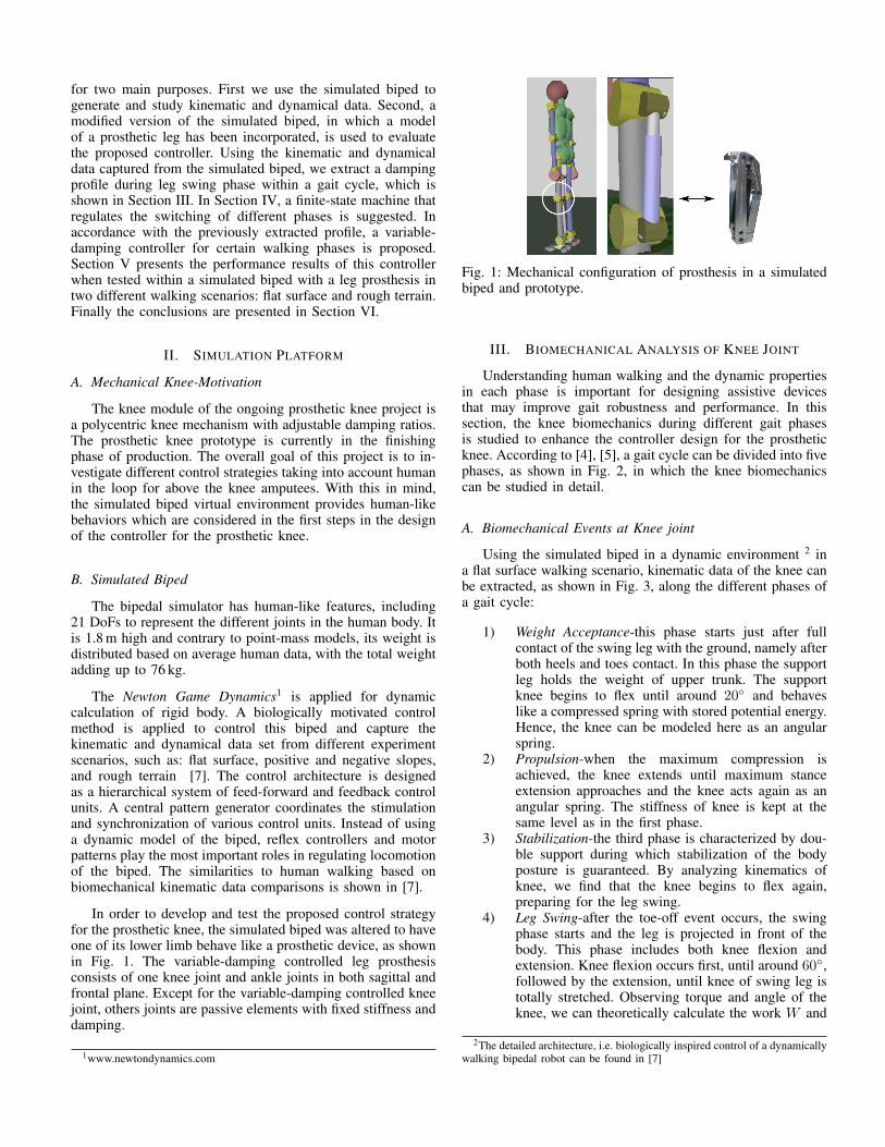
In order to develop and test the proposed control strategyfor the prosthetic knee, the simulated biped was altered to haveone of its lower limb behave like a prosthetic device, as shownin Fig. 1. The variable-damping controlled leg prosthesisconsists of one knee joint and ankle joints in both sagittal andfrontal plane. Except for the variable-damping controlled kneejoint, others joints are passive elements with fixed stiffness anddamping.
1www.newtondynamics.com
Fig. 1: Mechanical configuration of prosthesis in a simulatedbiped and prototype.
III. BIOMECHANICAL ANALYSIS OF KNEE JOINT
Understanding human walking and the dynamic propertiesin each phase is important for designing assistive devicesthat may improve gait robustness and performance. In thissection, the knee biomechanics during different gait phasesis studied to enhance the controller design for the prostheticknee. According to [4], [5], a gait cycle can be divided into fivephases, as shown in Fig. 2, in which the knee biomechanicscan be studied in detail.
A. Biomechanical Events at Knee joint
Using the simulated biped in a dynamic environment 2 ina flat surface walking scenario, kinematic data of the knee canbe extracted, as shown in Fig. 3, along the different phases ofa gait cycle:
1) Weight Acceptance-this phase starts just after fullcontact of the swing leg with the ground, namely afterboth heels and toes contact. In this phase the supportleg holds the weight of upper trunk. The supportknee begins to flex until around 20◦ and behaveslike a compressed spring with stored potential energy.Hence, the knee can be modeled here as an angularspring.
2) Propulsion-when the maximum compression isachieved, the knee extends until maximum stanceextension approaches and the knee acts again as anangular spring. The stiffness of knee is kept at thesame level as in the first phase.
3) Stabilization-the third phase is characterized by dou-ble support during which stabilization of the bodyposture is guaranteed. By analyzing kinematics ofknee, we find that the knee begins to flex again,preparing for the leg swing.
4) Leg Swing-after the toe-off event occurs, the swingphase starts and the leg is projected in front of thebody. This phase includes both knee flexion andextension. Knee flexion occurs first, until around 60◦,followed by the extension, until knee of swing leg istotally stretched. Observing torque and angle of theknee, we can theoretically calculate the work W and
2The detailed architecture, i.e. biologically inspired control of a dynamicallywalking bipedal robot can be found in [7]

Fig. 2: Walking phases for both legs and sensor events for switching phases [7].
power P on the knee joint as following:
W = τ · θ (1)P = τ · θ. (2)
Where τ denotes the torque and θ and θ are individu-ally the joint revolution and velocity. The knee powerconsumption is generally negative (see Fig. 3) since ithinders knee angular velocity. Therefore in the swingphase, the knee can be modeled as a variable damper.
5) Heel Strike-as soon as the swing leg’s knee is lockedor its heel contacts with the ground, the last phasebegins. It manages the foot impact during heel strikeand provides control concerning full contact of thefoot. The knee should be again stiff to handle theimpact of body weight.
B. Extraction of Damping Profile
As shown in Fig. 3, in the swing phase the knee generatesa resistant moment during leg extension. This negative powerportion of the gait cycle can be effectively modeled as avariable damper, as shown by the biomechanical analysis inSec. III-A. Therefore, the effective damping coefficient of theknee throughout swing extension is calculated using Eq. 3:
Bk =τk
θk. (3)
The effective damping variable Bk is the ratio between theknee torque τk and knee velocity θk.
By using the data set illustrated in Fig.3, we can calculatethe damping coefficient directly as shown in Eq. 3. From Fig 4,we see the knee damping Bk decreases sharply when kneestarts to flex from stance phase. Then Bk is mostly performingas a linear function of knee angle up to the maximum value ofknee flexion. After extension of the knee joint, Bk is nearlya linear function of knee angle between 20◦ and 50◦. Thedamping coefficient along the increase and decrease of theknee angle display similar courses during swing phase. Sincein the stance phase, the knee joint is stiff to keep stability ofthe upper body, we observe that its damping coefficient highlyincreases. Thus we only consider the damping coefficient in the
leg swing phase. According to Fig. 4, the damping coefficient
Fig. 3: Angle, velocity, torque and power consumption at kneejoint. The solid lines indicate mean values while dashed linesdenotes maximum and minimum values. The vertical dashedline denotes the toe-off event.

Fig. 4: Knee damping coefficient along the knee angle duringgait cycle.
can be represented as a function of the knee angle:
Bk(θk) =
Bklow+Bkup
−Bklow
θkup − θklow
· (θk − θklow) , if θk > θklow
∞, otherwise(4)
In Eq. 4 θklowand θkup represent a range in which knee joint
can be modeled as a variable damper whereas Bklowand Bkup
denote respectively the damping coefficient at θklowand θkup
.
IV. FINITE-STATE MACHINE FOR WALKING PHASES
From a biomechanical point of view, walking can bedivided into 5 distinct phases. However, in order to controla prosthetic leg based on these different walking phases, thoseevents and their features must be estimated in real-time. Wehave to use limited sensors mounted within the prostheticleg to decide the occurrence of critical events that indicatesswitching among the walking phases. The existing sensorson the prosthetic leg are encoders on each joint and fourload cells on each foot. As existence of a hierarchical controlarchitecture, sensor information are introduced into the CentralPattern Generators, i.e. CPG, which plays the role as a centralcontroller triggering the state of the walking phases.
A finite-state machine for cyclic walking is proposed torepresent a healthy knee, as illustrated in Fig. 2. Transitionsof gait phases are activated by three events, i.e., toe off, lockedknee and full contact. Therefore, the whole five gait phasescan actually be arranged in three states, which are Stabilization(ST), Swing (SW) and Heel Strike (HS), respectively. In orderto successfully activate the finite-state machine, the followingvariables are required:
• Knee angle (θk) indicates the relative angle of kneejoint. Fully extended knee angle denotes θk = 0.Maximum knee angle is 2 rad/s.
• Ankle angle (θa) denotes the relative angle of anklejoint in sagittal plane. Neutral position θa0
is setat the position that human is standing still. Positiveangles denote plantarflexion while negative denotedorsiflexion.
• Foot load (Fl) means loaded force on the foot basedon four force sensors respectively mounted on inner
Fig. 5: Transitions of finite state machine regulating gaitphases.
toe, outer toe, inner heel and outer heel. With
Fl =Fforce − Flow
Fup − Flow, if Fl ∈ [0, 1], (5)
where Fforce is the measured force, Flow and Fup
are respectively the lower and upper threshold of thevertical force on the feet. The value of Fl is limitedin [0, 1]. It can be divided into Heel Contact(H) andToe Contact(T), in which 1 means full contact while0 denotes no contact at all.
Figure 5 shows the proposed Finite State Machine and wecan now present an elaborate description:
1) Stabilization-when the heel strikes on the ground, thelanding knee joint bends a little due to the strongimpact. However it maintains around an equilibriumposition to support the weight of the upper body,acting as a locked mechanism. After the forwardtransferring of the center of mass, the stored energyis released. Meanwhile the opposite knee prepares tostart the swing. State switches when the followingtwo kinematic events occur:• the ground contact detected by force sensors
mounted on feet is smaller than a predefinedthreshold value, e.g. Fl < Fthreshold1 and
• due to plantarflexion of ankle joint, it growsup till larger than neutral angle, e.g. θa > θa0
.2) Swing-the swing phase starts after toe-off. The knee is
bent due to the inertia of the knee. The opposite kneeis again extended to the neutral angle to support thebody. As the knee flexes beyond θklow
, the dampingcontrol is applied to resist hyperflexion. The positiontracking in flexion phase is not necessary since itutilizes the passive dynamics of the knee joint. Thedamping coefficient is slightly increased coupled tothe knee angle until knee extension occurs. The kneeextension is caused by the gravity acting on the legand the torque generated at hip joint which make legextend and move forward. As in the beginning ofextension, the knee acts as a passive joint and there-fore no controller is required. Once the knee angleachieves the θkup , a damper controller is needed toprevent hyperflexion. Knee velocity is then graduallydecreased due to resista torques. When the knee jointpasses over θklow
and approaches the equilibriumposition, a lock mechanism will prevent the kneehyperextension. The transition to the next state, HeelStrike, happens when:

• the knee angle θk > θkthreshold2; or
• the ground contact Fl > Fthreshold2 , whichmeans heel of swing leg starts to land on theground.
3) Heel Strike-is responsible for reducing the groundimpact and for generating a lowering of the toesafter heel strike. Instead of modeling the knee jointas a variable damper, a locked mechanism withinthe knee joint is suggested to support the impactof landing. The finite-state machine turns again tothe Stabilization phase, if the following condition isfulfilled:• H > Hthreshold,
which means the heel strike is finished and the foothas made full contact with the ground.
V. SIMULATION AND RESULTS
This section presents the simulation results of the proposedcontroller on the simulated biped containing the leg prosthesison two distinct walking scenarios: flat surface and roughterrain.
A. Normal Walking on Flat Surface
The first tests conducted using the simulated biped werebased on normal walking at the speed of 1.21 m/s. It allowsa detailed evaluation of the proposed controller for the pros-thesis compared to a simulated healthy subject. The kineticand kinematic analysis give insight into joint trajectories andnecessary joint torques. Figure 6 shows the angle trajectories
Fig. 6: Joint angles over the course of gait cycle. Solid linesrepresent mean values, dashed lines mark the minimum andmaximum values, the vertical dashed line denotes the transitionfrom stance to swing. Left column healthy leg, right prosthesis.
of hip, knee and ankle joint in the sagittal plane, and anklein the frontal plane over the course of a gait cycle. Fifteen
consecutive steps of walking on flat ground are averaged bymanually tagging the sampling data from one heel strike tothe next. Positive values indicate, respectively, a joint flex-ion,abduction and dorsiflexion, while negative values denoteextension, adduction and plantarflexion. The solid lines showthe up-to-date average values of joint angles along gait cycleand dashed lines illustrate the maximum and minimum values.The vertical dashed line around 69% is the location of thetransition from stance to swing.
In Fig. 6, hip angles in the frontal plane of the prosthetic legand healthy leg are generally similar, which means amputeeswith this prosthesis do not need to adjust the amplitude ofhip swing in the swing phase and postures during the swingphase. We also found that the course of the knee angle at theprosthetic leg has closely the same profile of that in the healthyleg. That means the variable damping control has fulfilled thefunctionality as required. As for the ankle joint, there are somedifferences between the prosthetic leg and the healthy leg. In ahealthy leg, the ankle is actively controlled in the sagittal plane,meaning reflex controllers and motor patterns are applied atthis joint. However, due to the lack of stiffness control in theprosthetic leg, the lateral stability can not be guaranteed duringthe stance phase.
Fig. 7: Joint torques over the course of gait cycle. Solid linesrepresent mean values, dashed lines mark the minimum andmaximum values, the vertical dashed line denotes the transitionfrom stance to swing. Left column healthy leg, right prosthesis.
Figure 7 illustrates the torques in the joints in both cases.In the simulated biped the torque is a combination of puremotor torque and torque generated by a virtual spring or/anddamper. Torques at the hip frontal joint in both legs performvery close to each other. This means amputees do not need togenerate more energy to swing the leg. Looking at the kneejoints, based on the calculated damping profile, the prostheticknee produces enough torque to restrain its locomotion andtherefore achieve a very human-like walking gait.

B. Walking on Rough Terrain
The second series of tests were conducted on rough terrain.The simulated terrain is built with roughness of up to 33 mm,which is equivalent to randomly placing rocks or similarobstacles with this maximum height throughout the terrain.The kinematic and kinetic data from the prosthetic leg areillustrated in Fig. 8. The kinematic data show that the averageangle values are similar with those values in flat surfacewalking, but due to the rough terrain, angle values can varyin a wider range. However, with the variable-damping control,the biped can still walk very smoothly on this uneven terrain.Looking into the course of knee joint, we found that thetorque generated by the damper is less than that in normalwalking. This is because protuberances on the ground shortenthe duration of the swing phase and extend the stance phase.Ankle vibration in frontal plane, that results from unevennesson the ground, has impact especially on lateral stability. Inthis case, a constant stiffness control limits its adaptationto various environments. Hence a variable-stiffness controllerin this joint seems to be more comfortable for amputees indifferent walking scenarios.
Fig. 8: Prosthetic joint angles, left, and torques, right, over thecourse of gait cycle.
VI. CONCLUSION
In this paper, we presented a methodology for designinga variable-damping controller for a leg prosthesis using asimulated biped in a virtual environment. To control thephase-dependent prosthesis, we first studied the biomechanicalaspects of knee joint along walking cycle. We then performedsimulations and obtained such data from a virtual modelof human walking. Afterwards, we analyzed the kinetic andkinematic data and extracted a damping profile along walkingcycle. Based on this, we defined a finite-state machine andthe corresponding damping control for each state. At last, we
tested this methodology within this simulation environmentboth on flat ground and rough terrain. This is one greatadvantage of the proposed method, since the control strategymay be evaluated without any risk for humans. The resultinggait was satisfactory and robust to different environments.Future works include testing the developed control strategy onthe real prosthetic knee under development and expanding theproposed methodology for both active knee and ankle control.
ACKNOWLEDGMENT
We would like to thank DAAD3 and CAPES4 for fundingthis work.
REFERENCES
[1] R. R. Torrealba, G. Fernandez-Lopez, and J. C. Grieco, “Towardsthe development of knee prostheses: review of current researches,”Kybernetes, vol. 37, no. 9/10, pp. 1561–1576, 2008.
[2] Z. T. Harvey, B. K. Potter, J. Vandersea, and E. Wolf, “Prostheticadvances,” Journal of Surgical Orthopaedic Advances, vol. 21, no. 1,pp. 58–64, jan 2012.
[3] “Evaluation of function, performance, and preference as transfemoralamputees transition from mechanical to microprocessor control of theprosthetic knee.” Archives of Physical Medicine and Rehabilitation,vol. 88, no. 2, pp. 207–17, Feb. 2007.
[4] Y. P. Ivanenko, R. E. Poppele, and F. Lacquaniti, “Motor controlprograms and walking,” in The Neuroscientist, vol. 12, no. 4, 2006,pp. 339–348.
[5] C. Vaughan, B. Davis, and J. O’Connor, Dynamics of Human Gait,2nd ed. Kiboho Publishers, 1999.
[6] Y. P. Ivanenko, R. E. Poppele, and F. Lacquaniti, “Five basic muscle ac-tivation patterns account for muscle activity during human locomotion,”Journal of Physiology, vol. 556, 2004.
[7] T. Luksch, Human-like Control of Dynamically Walking Bipedal Robots,ser. RRLab Dissertations. Verlag Dr. Hut, 2010, iSBN 978-3-86853-607-2.
[8] E. C. Martinez-villalpando and H. Herr, “Agonist-antagonist active kneeprosthesis: A preliminary study in level-ground walking,” Journal ofRehabilitation Research and Development, vol. 46, no. 3, pp. 361–373,2009.
[9] J. L. Johansson, D. M. Sherrill, P. O. Riley, P. Bonato, and H. Herr, “AClinical Comparison of Variable-Damping and Mechanically PassiveProsthetic Knee Devices,” American Journal of Physical Medicine &Rehabilitation, vol. 84, no. 8, pp. 563–575, aug 2005.
[10] R. Davoodi, C. Urata, M. Hauschild, M. Khachani, and G. E. Loeb,“Model-based development of neural prostheses for movement.” IEEETransactions on Bio-medical Engineering, vol. 54, no. 11, pp. 1909–18,Nov. 2007.
[11] A. K. LaPre and F. Sup, “Simulation of a slope adapting ankle prosthesisprovided by semi-active damping.” IEEE Conference of the Engineeringin Medicine and Biology Society, EMBS, vol. 2011, pp. 587–90, Jan.2011.
[12] R. W. Sinnet, H. Zhao, and A. D. Ames, “Simulating prostheticdevices with human-inspired hybrid control,” in IEEE/RSJ InternationalConference on Intelligent Robots and Systems, IROS. IEEE, Sep. 2011,pp. 1723–1730.
[13] S. Pejhan, F. Farahmand, and M. Parnianpour, “Design optimizationof an above-knee prosthesis based on the kinematics of gait.” in IEEEConference of the Engineering in Medicine and Biology Society, EMBS,vol. 2008, Jan. 2008, pp. 4274–7.
[14] A. Melendez-Calderon, H. A. Caltenco-Arciniega, S. Dosen, and J. E.Chong-Quero, “On-line Simulation Tool for the Design and Analysisof Lower-limb Prosthetic Devices,” in International Conference onElectrical and Electronics Engineering, ICEEE. IEEE, Sep. 2007,pp. 98–101.
3www.daad.de4www.capes.gov.br