Embed Size (px)
Citation preview
ISSN: 2237-0722
Vol. 11 No. 4 (2021)
Received: 30.05.2021 – Accepted: 28.06.2021
2368
Design of Two Element Triple Band MIMO DRA with Enhanced Isolation for LTE
Applications
Varakumari Samudrala1*; Vinay Kumar Pamula2 1*Department of ECE, UCEK, JNTUK, Kakinada, India.
1*[email protected] 2Department of ECE, UCEK, JNTUK, Kakinada, India.
Abstract
A new two element hybrid MIMO DRA is presented for LTE operation. The presented MIMO having
two elements excited with CPW feeding. This is operating under hybrid TM mode. MIMO is intended
on partial ground with thickness of 0.035 mm, substrate (FR-4) with dielectric constant (εr) of 4.6,
thickness 1.6 mm and loss tangent 0.019. The DRA is placed on the two elements individually. The
dimensions of the presented MIMO are 90 X 107.8 X 13 mm3. The antenna gives a multiband to
covers 0.8 GHz, 1.5 GHz, and 1.7 GHz for |S11| ≤ -10 dB. The proposed MIMO can cover LTE Band
5 and Band 6 at 0.84 GHz with operating band width of 83.2 MHz (0.8106 – 0.8938 GHz), LTE Band
21 at 1.5 GHz with operating band width of 45.4 MHz (1.4825 – 1.5279 GHz) and LTE Band 9 at 1.7
GHz with operating band with is 72.6 MHz (1.7382 – 1.8108 GHz). The simulated isolation of -74.96
dB, -75.53 dB and -81.41 dB are obtained with respect to the mentioned frequencies, respectively.
MIMO provides very good radiation efficiency >140 % at band-1, > 81% at band-2 and >82% at
band-3. The proposed antenna is discovered to attain good isolation, better impedance matching, low
Envelope Correlation Coefficient (ECC) and adequate gain. Hence, This MIMO suitable for LTE
applications. The HFSS software is used for the simulation.
Key-words: Isolation, LTE Bands, Multiband, DRA, ECC.
1. Introduction
The highlights of antenna like high radiation efficiency, more bandwidths are achieved the
focus of the investigators on Dielectric Resonating Antenna (DRA). In the Wireless communication
technology, the current trend needs high data rates and more band widths to convey the information.
But these parameters are limited. Hence, to meet these requirements we adopted another technique,
ISSN: 2237-0722
Vol. 11 No. 4 (2021)
Received: 30.05.2021 – Accepted: 28.06.2021
2369
i.e., the use of Multiple Input and Multiple Outputs (MIMO) system. This increases the data rates and
improves the system response [1]-[2]. The operating frequency for LTE from 400 MHz to 4 GHz. [3].
To improve the data rates MIMO with small size is preferred for 4G applications. Multiband MIMO
technology with less mutual coupling to provide high data rates for wireless transmission [4]-[6].
MIMO system innovation is adapted to increase the data rate mean while we have maintained the less
separation distance between the ports. If the space between the antennas is less again there is problem
with mutual coupling. Hence, while designing the MIMO system, increase the isolation and decrease
the envelope correlation coefficient to improve the diversity. Wireless technology wherever several
piers are utilized at source and destination [7]. MIMO mainly aimed to improve the information rate
and minimizes the errors. To get more information speed or gathering MIMO idea is embraced in
little appliances. MIMO antennas provide more data rates and radiation efficiency. The overall
performance is more effective [8]-[9]. The single component MIMO reception apparatuses are
precisely solid, have insignificant mis mount blunders, and simple to create when contrasted with
multi components, however the issue is to achieve high separation between radiating elements and
having very low Envelope Correlation Coefficient (ECC). Very recently so many articles given most
effective solutions is presented to focus on this problem [10]-[19]. In this research work, we propose
a 2-radiating-element MIMO DRA system solution enabling multiband behavior, High isolation and
low ECC, and high efficiency. This article presents a two -element multiband DRA for 4G
applications.
The antenna is designed using meander line patches, whereas substrate of 1.6 mm height and
ground having thickness of 0.035 mm and ground considered as partial ground structure. The CPW
feeding with two elements placed symmetrically which provides less mutual coupling among supply
elements and verse radiation configuration which minimizes the delay among radiating elements. The
presented multiband MIMO is easy to construct. In this presented MIMO, the reference level
considered for impedance bandwidth is – 10 dB and for isolation bandwidth is- 15 dB.
2. Antenna Geometry
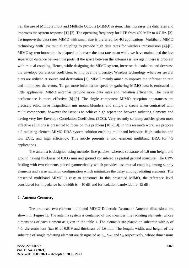
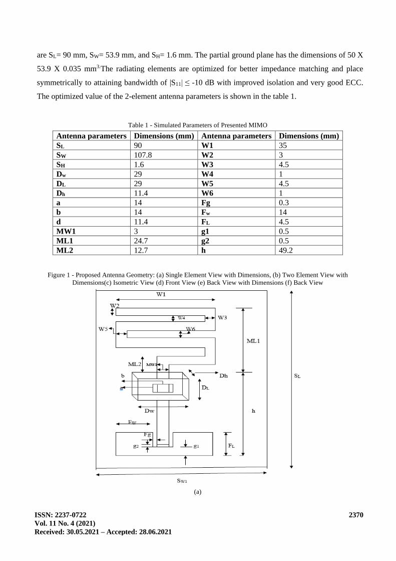
The proposed two-element multiband MIMO Dielectric Resonator Antenna dimensions are
shown in [Figure 1]. The antenna system is contained of two meander line radiating elements, whose
dimensions of each element as given in the table 1. The elements are placed on substrate with εr of
4.6, dielectric loss (tan δ) of 0.019 and thickness of 1.6 mm. The length, width, and height of the
substrate of single radiating element are designated as SL, SW, and SH respectively, whose dimensions
ISSN: 2237-0722
Vol. 11 No. 4 (2021)
Received: 30.05.2021 – Accepted: 28.06.2021
2370
are SL= 90 mm, SW= 53.9 mm, and SH= 1.6 mm. The partial ground plane has the dimensions of 50 X
53.9 X 0.035 mm3.The radiating elements are optimized for better impedance matching and place
symmetrically to attaining bandwidth of |S11| ≤ -10 dB with improved isolation and very good ECC.
The optimized value of the 2-element antenna parameters is shown in the table 1.
Table 1 - Simulated Parameters of Presented MIMO
Antenna parameters Dimensions (mm) Antenna parameters Dimensions (mm)
SL 90 W1 35
SW 107.8 W2 3
SH 1.6 W3 4.5
Dw 29 W4 1
DL 29 W5 4.5
Dh 11.4 W6 1
a 14 Fg 0.3
b 14 Fw 14
d 11.4 FL 4.5
MW1 3 g1 0.5
ML1 24.7 g2 0.5
ML2 12.7 h 49.2
Figure 1 - Proposed Antenna Geometry: (a) Single Element View with Dimensions, (b) Two Element View with
Dimensions(c) Isometric View (d) Front View (e) Back View with Dimensions (f) Back View
(a)
ISSN: 2237-0722
Vol. 11 No. 4 (2021)
Received: 30.05.2021 – Accepted: 28.06.2021
2371
(b)
(c) (d)
(e) (f)
ISSN: 2237-0722
Vol. 11 No. 4 (2021)
Received: 30.05.2021 – Accepted: 28.06.2021
2372
3. Design and Analysis
To design an antenna certain steps to be follow, initially single element antenna study has
been done and then two element antennas has designed with and without hole inside the DRA. The
observations of the responses of two element without hole antenna assisted to get best model, and
then simulated.
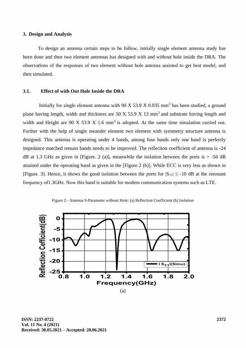
3.1. Effect of with Out Hole Inside the DRA
Initially for single element antenna with 90 X 53.9 X 0.035 mm3 has been studied, a ground
plane having length, width and thickness are 50 X 53.9 X 13 mm3 and substrate having length and
width and Height are 90 X 53.9 X 1.6 mm3 is adopted. At the same time simulation carried out.
Further with the help of single meander element two element with symmetry structure antenna is
designed. This antenna is operating under 4 bands, among four bands only one band is perfectly
impedance matched remain bands needs to be improved. The reflection coefficient of antenna is -24
dB at 1.3 GHz as given in [Figure. 2 (a)], meanwhile the isolation between the ports is > -56 dB
attained under the operating band as given in the [Figure 2 (b)]. While ECC is very less as shown in
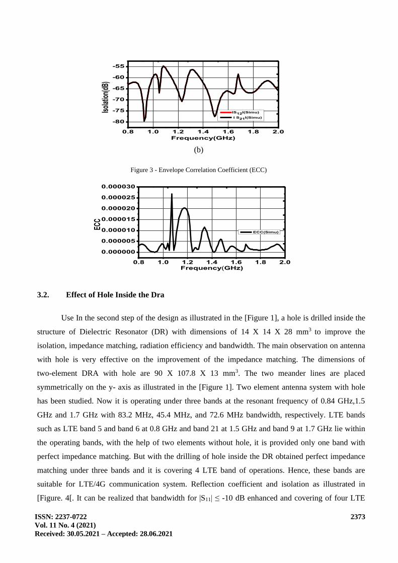
[Figure. 3]. Hence, it shows the good isolation between the ports for |S11| ≤ -10 dB at the resonant
frequency of1.3GHz. Now this band is suitable for modern communication systems such as LTE.
Figure 2 - Antenna S-Parameter without Hole: (a) Reflection Coefficient (b) Isolation
0.8 1.0 1.2 1.4 1.6 1.8 2.0-25
-20
-15
-10
-5
0
I S11I(Simu)
Ref
lect
ion
Cef
ficie
nt(d
B)
Frequency(GHz)
(a)
ISSN: 2237-0722
Vol. 11 No. 4 (2021)
Received: 30.05.2021 – Accepted: 28.06.2021
2373
0.8 1.0 1.2 1.4 1.6 1.8 2.0
-80
-75
-70
-65
-60
-55
IS12I(Simu)
I S21I(Simu)
Isol
atio
n(dB
)
Frequency(GHz)
(b)
Figure 3 - Envelope Correlation Coefficient (ECC)
0.8 1.0 1.2 1.4 1.6 1.8 2.0
0.000000
0.000005
0.000010
0.000015
0.000020
0.000025
0.000030
ECC(Simu)
ECC
Frequency(GHz)
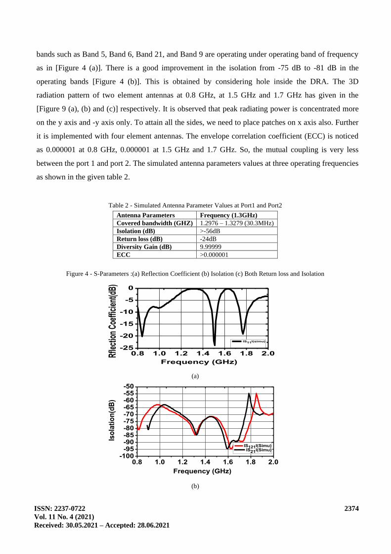
3.2. Effect of Hole Inside the Dra
Use In the second step of the design as illustrated in the [Figure 1], a hole is drilled inside the
structure of Dielectric Resonator (DR) with dimensions of 14 X 14 X 28 mm3 to improve the
isolation, impedance matching, radiation efficiency and bandwidth. The main observation on antenna
with hole is very effective on the improvement of the impedance matching. The dimensions of
two-element DRA with hole are 90 X 107.8 X 13 mm3. The two meander lines are placed
symmetrically on the y- axis as illustrated in the [Figure 1]. Two element antenna system with hole
has been studied. Now it is operating under three bands at the resonant frequency of 0.84 GHz,1.5
GHz and 1.7 GHz with 83.2 MHz, 45.4 MHz, and 72.6 MHz bandwidth, respectively. LTE bands
such as LTE band 5 and band 6 at 0.8 GHz and band 21 at 1.5 GHz and band 9 at 1.7 GHz lie within
the operating bands, with the help of two elements without hole, it is provided only one band with
perfect impedance matching. But with the drilling of hole inside the DR obtained perfect impedance
matching under three bands and it is covering 4 LTE band of operations. Hence, these bands are
suitable for LTE/4G communication system. Reflection coefficient and isolation as illustrated in
[Figure. 4[. It can be realized that bandwidth for |S11| ≤ -10 dB enhanced and covering of four LTE
ISSN: 2237-0722
Vol. 11 No. 4 (2021)
Received: 30.05.2021 – Accepted: 28.06.2021
2374
bands such as Band 5, Band 6, Band 21, and Band 9 are operating under operating band of frequency
as in [Figure 4 (a)]. There is a good improvement in the isolation from -75 dB to -81 dB in the
operating bands [Figure 4 (b)]. This is obtained by considering hole inside the DRA. The 3D
radiation pattern of two element antennas at 0.8 GHz, at 1.5 GHz and 1.7 GHz has given in the
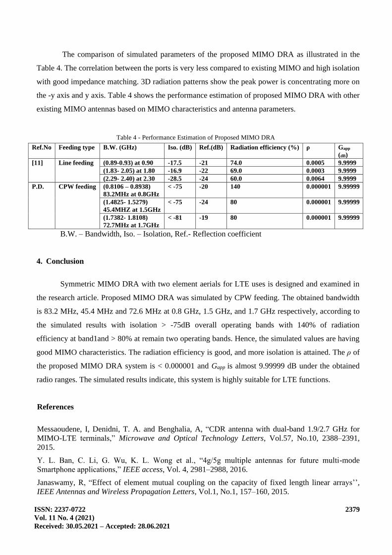
[Figure 9 (a), (b) and (c)] respectively. It is observed that peak radiating power is concentrated more
on the y axis and -y axis only. To attain all the sides, we need to place patches on x axis also. Further
it is implemented with four element antennas. The envelope correlation coefficient (ECC) is noticed
as 0.000001 at 0.8 GHz, 0.000001 at 1.5 GHz and 1.7 GHz. So, the mutual coupling is very less
between the port 1 and port 2. The simulated antenna parameters values at three operating frequencies
as shown in the given table 2.
Table 2 - Simulated Antenna Parameter Values at Port1 and Port2
Antenna Parameters Frequency (1.3GHz)
Covered bandwidth (GHZ) 1.2976 – 1.3279 (30.3MHz)
Isolation (dB) >-56dB
Return loss (dB) -24dB
Diversity Gain (dB) 9.99999
ECC >0.000001
Figure 4 - S-Parameters :(a) Reflection Coefficient (b) Isolation (c) Both Return loss and Isolation
0.8 1.0 1.2 1.4 1.6 1.8 2.0-25
-20
-15
-10
-5
0
Rfle
ctio
n Co
effic
ient
(dB)
Frequency (GHz)
IS11I(simu)
(a)
0.8 1.0 1.2 1.4 1.6 1.8 2.0-100
-95-90-85-80-75-70-65-60-55-50
Iso
lati
on
(dB
)
Frequency (GHz)
IS121I(Simu)
IS21I(Simu)
(b)
ISSN: 2237-0722
Vol. 11 No. 4 (2021)
Received: 30.05.2021 – Accepted: 28.06.2021
2375
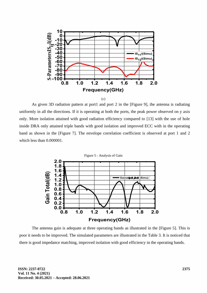
0.8 1.0 1.2 1.4 1.6 1.8 2.0-100
-90-80-70-60-50-40-30-20-10
010
IS11I(Simu)
IS12I(Simu)
S-P
aram
eter
sIS
ijI(
dB
)
Frequency(GHz)
(c)
As given 3D radiation pattern at port1 and port 2 in the [Figure 9], the antenna is radiating
uniformly in all the directions. If it is operating at both the ports, the peak power observed on y axis
only. More isolation attained with good radiation efficiency compared to [13] with the use of hole
inside DRA only attained triple bands with good isolation and improved ECC with in the operating
band as shown in the [Figure 7]. The envelope correlation coefficient is observed at port 1 and 2
which less than 0.000001.
Figure 5 - Analysis of Gain
0.8 1.0 1.2 1.4 1.6 1.8 2.00.00.20.40.60.81.01.21.41.61.82.0
Gainat= = (Simu)
Gai
n T
ota
l(d
B)
Frequency(GHz)
The antenna gain is adequate at three operating bands as illustrated in the [Figure 5]. This is
poor it needs to be improved. The simulated parameters are illustrated in the Table 3. It is noticed that
there is good impedance matching, improved isolation with good efficiency in the operating bands.
ISSN: 2237-0722
Vol. 11 No. 4 (2021)
Received: 30.05.2021 – Accepted: 28.06.2021
2376
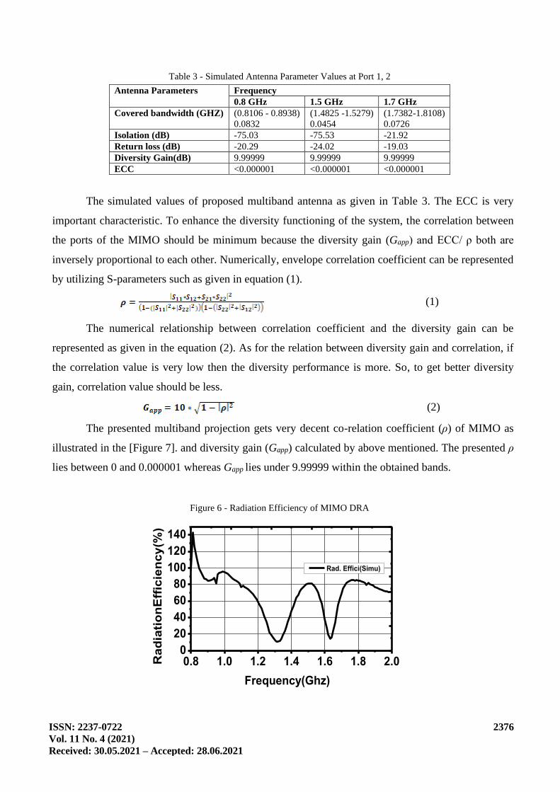
Table 3 - Simulated Antenna Parameter Values at Port 1, 2
Antenna Parameters Frequency
0.8 GHz 1.5 GHz 1.7 GHz
Covered bandwidth (GHZ) (0.8106 - 0.8938)
0.0832
(1.4825 -1.5279)
0.0454
(1.7382-1.8108)
0.0726
Isolation (dB) -75.03 -75.53 -21.92
Return loss (dB) -20.29 -24.02 -19.03
Diversity Gain(dB) 9.99999 9.99999 9.99999
ECC <0.000001 <0.000001 <0.000001
The simulated values of proposed multiband antenna as given in Table 3. The ECC is very
important characteristic. To enhance the diversity functioning of the system, the correlation between
the ports of the MIMO should be minimum because the diversity gain (Gapp) and ECC/ ρ both are
inversely proportional to each other. Numerically, envelope correlation coefficient can be represented
by utilizing S-parameters such as given in equation (1).
(1)
The numerical relationship between correlation coefficient and the diversity gain can be
represented as given in the equation (2). As for the relation between diversity gain and correlation, if
the correlation value is very low then the diversity performance is more. So, to get better diversity
gain, correlation value should be less.
(2)
The presented multiband projection gets very decent co-relation coefficient (ρ) of MIMO as
illustrated in the [Figure 7]. and diversity gain (Gapp) calculated by above mentioned. The presented ρ
lies between 0 and 0.000001 whereas Gapp lies under 9.99999 within the obtained bands.
Figure 6 - Radiation Efficiency of MIMO DRA
0.8 1.0 1.2 1.4 1.6 1.8 2.00
20
40
60
80
100
120
140
Rad. Effici(Simu)
Rad
iati
on
Eff
icie
ncy
(%)
Frequency(Ghz)
ISSN: 2237-0722
Vol. 11 No. 4 (2021)
Received: 30.05.2021 – Accepted: 28.06.2021
2377
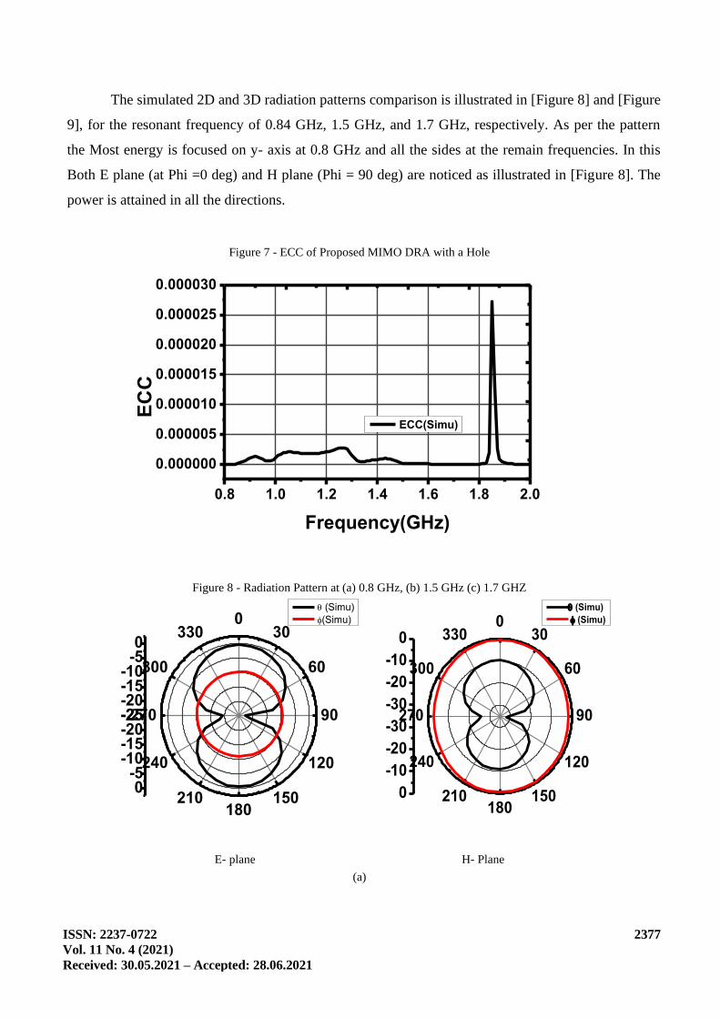
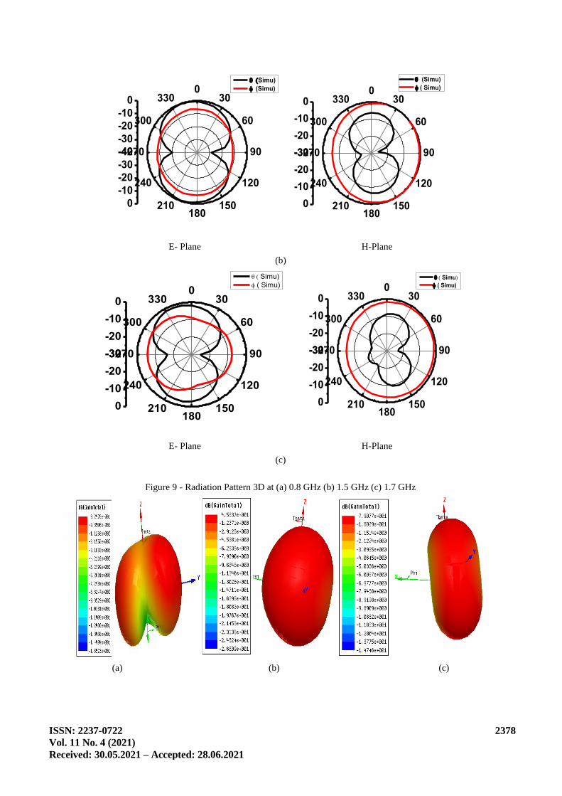
The simulated 2D and 3D radiation patterns comparison is illustrated in [Figure 8] and [Figure
9], for the resonant frequency of 0.84 GHz, 1.5 GHz, and 1.7 GHz, respectively. As per the pattern
the Most energy is focused on y- axis at 0.8 GHz and all the sides at the remain frequencies. In this
Both E plane (at Phi =0 deg) and H plane (Phi = 90 deg) are noticed as illustrated in [Figure 8]. The
power is attained in all the directions.
Figure 7 - ECC of Proposed MIMO DRA with a Hole
0.8 1.0 1.2 1.4 1.6 1.8 2.0
0.000000
0.000005
0.000010
0.000015
0.000020
0.000025
0.000030
ECC(Simu)
EC
C
Frequency(GHz)
Figure 8 - Radiation Pattern at (a) 0.8 GHz, (b) 1.5 GHz (c) 1.7 GHZ
-25-20-15-10
-50
030
60
90
120
150180
210
240
270
300
330
-25-20-15-10
-50
(Simu)
(Simu)
-30
-20
-10
00
30
60
90
120
150180
210
240
270
300
330
-30
-20
-10
0
(Simu)
(Simu)
E- plane H- Plane
(a)
ISSN: 2237-0722
Vol. 11 No. 4 (2021)
Received: 30.05.2021 – Accepted: 28.06.2021
2378
-40
-30
-20
-10
00
30
60
90
120
150180
210
240
270
300
330
-40
-30
-20
-10
0
(Simu)
(Simu)
-30
-20
-10
00
30
60
90
120
150180
210
240
270
300
330
-30
-20
-10
0
(Simu)
( Simu)
E- Plane H-Plane
(b)
-30
-20
-10
00
30
60
90
120
150180
210
240
270
300
330
-30
-20
-10
0
( Simu)
( Simu)
-30
-20
-10
00
30
60
90
120
150180
210
240
270
300
330
-30
-20
-10
0
( Simu)
( Simu)
E- Plane H-Plane
(c)
Figure 9 - Radiation Pattern 3D at (a) 0.8 GHz (b) 1.5 GHz (c) 1.7 GHz
(a) (b) (c)
ISSN: 2237-0722
Vol. 11 No. 4 (2021)
Received: 30.05.2021 – Accepted: 28.06.2021
2379
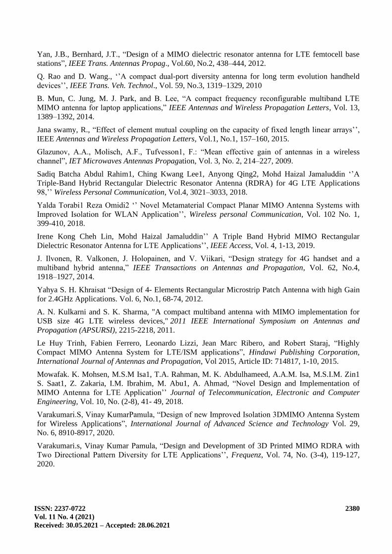
The comparison of simulated parameters of the proposed MIMO DRA as illustrated in the
Table 4. The correlation between the ports is very less compared to existing MIMO and high isolation
with good impedance matching. 3D radiation patterns show the peak power is concentrating more on
the -y axis and y axis. Table 4 shows the performance estimation of proposed MIMO DRA with other
existing MIMO antennas based on MIMO characteristics and antenna parameters.
Table 4 - Performance Estimation of Proposed MIMO DRA
Ref.No Feeding type B.W. (GHz) Iso. (dB) Ref.(dB) Radiation efficiency (%) ρ Gapp
(dB)
[11] Line feeding (0.89-0.93) at 0.90 -17.5 -21 74.0 0.0005 9.9999
(1.83- 2.05) at 1.80 -16.9 -22 69.0 0.0003 9.9999
(2.29- 2.40) at 2.30 -28.5 -24 60.0 0.0064 9.9999
P.D. CPW feeding (0.8106 – 0.8938)
83.2MHz at 0.8GHz
< -75 -20
140
0.000001 9.99999
(1.4825- 1.5279)
45.4MHZ at 1.5GHz
< -75 -24 80 0.000001 9.99999
(1.7382- 1.8108)
72.7MHz at 1.7GHz
< -81 -19 80 0.000001 9.99999
B.W. – Bandwidth, Iso. – Isolation, Ref.- Reflection coefficient
4. Conclusion
Symmetric MIMO DRA with two element aerials for LTE uses is designed and examined in
the research article. Proposed MIMO DRA was simulated by CPW feeding. The obtained bandwidth
is 83.2 MHz, 45.4 MHz and 72.6 MHz at 0.8 GHz, 1.5 GHz, and 1.7 GHz respectively, according to
the simulated results with isolation > -75dB overall operating bands with 140% of radiation
efficiency at band1and > 80% at remain two operating bands. Hence, the simulated values are having
good MIMO characteristics. The radiation efficiency is good, and more isolation is attained. The ρ of
the proposed MIMO DRA system is < 0.000001 and Gapp is almost 9.99999 dB under the obtained
radio ranges. The simulated results indicate, this system is highly suitable for LTE functions.
References
Messaoudene, I, Denidni, T. A. and Benghalia, A, “CDR antenna with dual-band 1.9/2.7 GHz for
MIMO-LTE terminals,” Microwave and Optical Technology Letters, Vol.57, No.10, 2388–2391,
2015.
Y. L. Ban, C. Li, G. Wu, K. L. Wong et al., “4g/5g multiple antennas for future multi-mode
Smartphone applications,” IEEE access, Vol. 4, 2981–2988, 2016.
Janaswamy, R, “Effect of element mutual coupling on the capacity of fixed length linear arrays’’,
IEEE Antennas and Wireless Propagation Letters, Vol.1, No.1, 157–160, 2015.
ISSN: 2237-0722
Vol. 11 No. 4 (2021)
Received: 30.05.2021 – Accepted: 28.06.2021
2380
Yan, J.B., Bernhard, J.T., “Design of a MIMO dielectric resonator antenna for LTE femtocell base
stations”, IEEE Trans. Antennas Propag., Vol.60, No.2, 438–444, 2012.
Q. Rao and D. Wang., ‘’A compact dual-port diversity antenna for long term evolution handheld
devices’’, IEEE Trans. Veh. Technol., Vol. 59, No.3, 1319–1329, 2010
B. Mun, C. Jung, M. J. Park, and B. Lee, “A compact frequency reconfigurable multiband LTE
MIMO antenna for laptop applications,” IEEE Antennas and Wireless Propagation Letters, Vol. 13,
1389–1392, 2014.
Jana swamy, R., “Effect of element mutual coupling on the capacity of fixed length linear arrays’’,
IEEE Antennas and Wireless Propagation Letters, Vol.1, No.1, 157–160, 2015.
Glazunov, A.A., Molisch, A.F., Tufvesson1, F.: “Mean effective gain of antennas in a wireless
channel”, IET Microwaves Antennas Propagation, Vol. 3, No. 2, 214–227, 2009.
Sadiq Batcha Abdul Rahim1, Ching Kwang Lee1, Anyong Qing2, Mohd Haizal Jamaluddin ‘’A
Triple-Band Hybrid Rectangular Dielectric Resonator Antenna (RDRA) for 4G LTE Applications
98,’’ Wireless Personal Communication, Vol.4, 3021–3033, 2018.
Yalda Torabi1 Reza Omidi2 ‘’ Novel Metamaterial Compact Planar MIMO Antenna Systems with
Improved Isolation for WLAN Application’’, Wireless personal Communication, Vol. 102 No. 1,
399-410, 2018.
Irene Kong Cheh Lin, Mohd Haizal Jamaluddin’’ A Triple Band Hybrid MIMO Rectangular
Dielectric Resonator Antenna for LTE Applications’’, IEEE Access, Vol. 4, 1-13, 2019.
J. Ilvonen, R. Valkonen, J. Holopainen, and V. Viikari, “Design strategy for 4G handset and a
multiband hybrid antenna,” IEEE Transactions on Antennas and Propagation, Vol. 62, No.4,
1918–1927, 2014.
Yahya S. H. Khraisat “Design of 4- Elements Rectangular Microstrip Patch Antenna with high Gain
for 2.4GHz Applications. Vol. 6, No.1, 68-74, 2012.
A. N. Kulkarni and S. K. Sharma, "A compact multiband antenna with MIMO implementation for
USB size 4G LTE wireless devices," 2011 IEEE International Symposium on Antennas and
Propagation (APSURSI), 2215-2218, 2011.
Le Huy Trinh, Fabien Ferrero, Leonardo Lizzi, Jean Marc Ribero, and Robert Staraj, “Highly
Compact MIMO Antenna System for LTE/ISM applications”, Hindawi Publishing Corporation,
International Journal of Antennas and Propagation, Vol 2015, Article ID: 714817, 1-10, 2015.
Mowafak. K. Mohsen, M.S.M Isa1, T.A. Rahman, M. K. Abdulhameed, A.A.M. Isa, M.S.I.M. Zin1
S. Saat1, Z. Zakaria, I.M. Ibrahim, M. Abu1, A. Ahmad, “Novel Design and Implementation of
MIMO Antenna for LTE Application’’ Journal of Telecommunication, Electronic and Computer
Engineering, Vol. 10, No. (2-8), 41- 49, 2018.
Varakumari.S, Vinay KumarPamula, “Design of new Improved Isolation 3DMIMO Antenna System
for Wireless Applications”, International Journal of Advanced Science and Technology Vol. 29,
No. 6, 8910-8917, 2020.
Varakumari.s, Vinay Kumar Pamula, “Design and Development of 3D Printed MIMO RDRA with
Two Directional Pattern Diversity for LTE Applications’’, Frequenz, Vol. 74, No. (3-4), 119-127,
2020.