Embed Size (px)
Citation preview
1
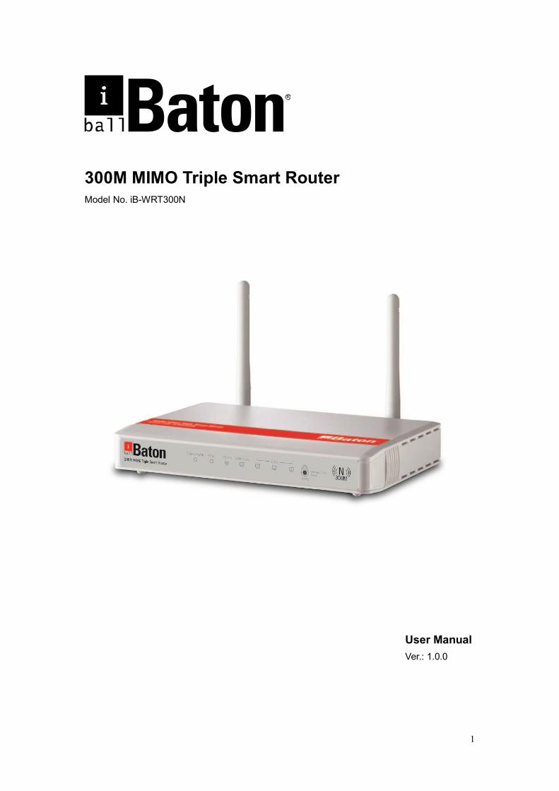
300M MIMO Triple Smart Router Model No. iB-WRT300N
User Manual Ver.: 1.0.0
2
FCC STATEMENT
This equipment has been tested and found to comply with the limits for a Class B digital device, pursuant to part 15 of the FCC Rules. These limits are designed to provide reasonable protection against harmful interference in a residential installation. This equipment generates uses and can radiate radio frequency energy and, if not in-stalled and used in accordance with the instructions, may cause harmful interference to radio communications. However, there is no guarantee that interference will not occur in a particular installation. If this equipment does cause harmful interference to radio or television reception, which can be determined by turning the equipment off and on, the user is encouraged to try to correct the interference by one or more of the following measures:
Reorient or relocate the receiving antenna.
Increase the separation between the equipment and receiver.
Connect the equipment into an outlet on a circuit different from that to which the receiver is connected.
Consult the dealer or an experienced radio/ TV technician for help.
This device complies with part 15 of the FCC Rules. Operation is subject to the following two conditions:
1) This device may not cause harmful interference.
2) This device must accept any interference received, including interference that may cause undesired operation.
Any changes or modifications not expressly approved by the party responsible for compliance could void the user’s authority to operate the equipment.

3
CE Mark Warning
This is a class B product. In a domestic environment, this product may cause radio interference, in which case the user may be required to take adequate measures.
4
TABLE OF CONTENTS
300M MIMO TRIPLE SMART ROUTER 1
CHAPTER 1 INTRODUCTION 5
CHAPTER 2. EASY SETUP WIZARD UTILITY 9
CHAPTER 3 ROUTER CONFIGURATION 19
PORT FORWARDING 39
SECURITY SETTINGS 46
ADVANCED SETTINGS 46
SYSTEM TOOLS 58
CHAPTER 4 TROUBLESHOOTING 61
APPENDIX A. SPEC SUMMARY TABLE 65
APPENDIX B. GLOSSARY 67
APPENDIX C. CONTACT INFORMATION 70
5
Chapter 1 . Introduction
iBall Baton 300M MIMO Triple smart Router complies with IEEE 802.11 b/g/n wireless
standards.
MIMO Technology - Wireless Transmission speed up to 300Mbps.
Triple Smart Router Supports ADSL Internet (xDSL): 1 - 10/100M RJ11 WAN port
Supports Broadband Internet (Cable / DSL): 1 - 10/100M RJ45 WAN port
Supports 2G/3G Internet (GSM/CDMA) - USB slot for wireless modem
Easy Setup Wizard - Utility helps users to configure the router easily.
1.1Package List
300M MIMO Triple Smart Router (iB-WRT300N)
2 Antenna (Fixed)
Power Adapter
RJ45 Patch cord
ADSL Splitter
RJ11 Patch cord
USB Cable
Cd
Quick Installation Guide
Note:
Make sure that the package contains the above items. If any of the listed items are damaged
or missing, please contact your nearest dealer.
6
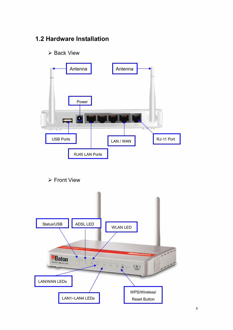
1.2 Hardware Installation
Back View
Front View
Antenna
Power
Antenna
RJ45 LAN Ports
RJ-11 Port LAN / WAN
LAN1~LAN4 LEDs
WLAN LED ADSL LED Status/USB
WPS/Wireless/
Reset Button
LAN/WAN LEDs
USB Ports
7
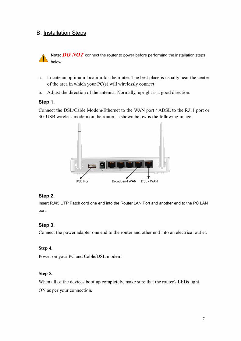
B. Installation Steps
Note: DO NOT connect the router to power before performing the installation steps
below.
a. Locate an optimum location for the router. The best place is usually near the center
of the area in which your PC(s) will wirelessly connect.
b. Adjust the direction of the antenna. Normally, upright is a good direction.
Step 1. Connect the DSL/Cable Modem/Ethernet to the WAN port / ADSL to the RJ11 port or 3G USB wireless modem on the router as shown below is the following image.
USB Port Broadband WAN DSL - WAN
Step 2. Insert RJ45 UTP Patch cord one end into the Router LAN Port and another end to the PC LAN
port.
Step 3. Connect the power adapter one end to the router and other end into an electrical outlet.
Step 4.
Power on your PC and Cable/DSL modem.
Step 5.
When all of the devices boot up completely, make sure that the router's LEDs light
ON as per your connection.

8
1.2.2 LED indicators
LED Status Description
Status (USB)
Green in flash Power is on
Green in fast flash
Reset mode
Green 2G /3G USB modem
Green in flash Data access
ADSL Green in flash xDSL connection is established
Green in fast flash
Data packet transferred via DSL Line
WLAN Green WiFi is on.
Green in flash Data access
LAN Green
RJ45 cable is plugged, and Ethernet connection is established.
Green in flash Data access
How to Operate Step 1.
Plug the RJ45 cable into LAN port 1~4 and
connect with your Computer or Laptop.
Step 2
Connect 2G/3G dongle and then plug into
the USB port.
Or
9
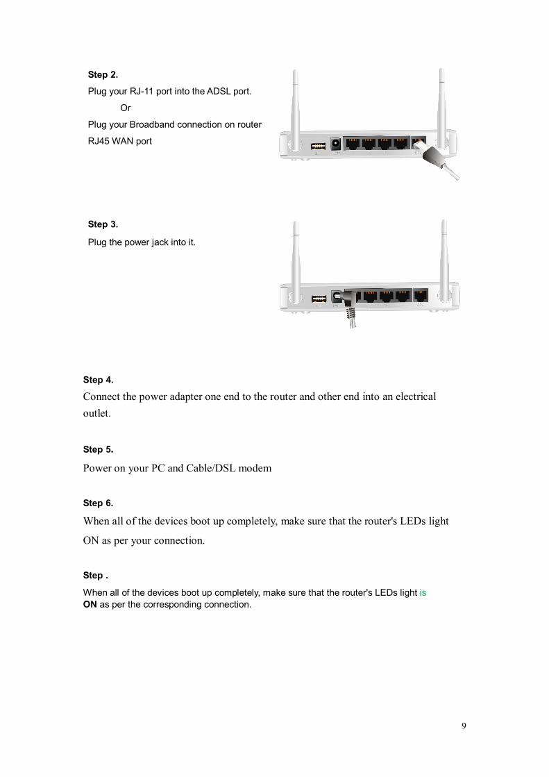
Step 2.
Plug your RJ-11 port into the ADSL port.
Or
Plug your Broadband connection on router
RJ45 WAN port
Step 3.
Plug the power jack into it.
Step 4.
Connect the power adapter one end to the router and other end into an electrical outlet.
Step 5.
Power on your PC and Cable/DSL modem
Step 6.
When all of the devices boot up completely, make sure that the router's LEDs light
ON as per your connection.
Step .
When all of the devices boot up completely, make sure that the router's LEDs light is ON as per the corresponding connection.

10
Chapter 2. Easy Setup Wizard
There are two methods for you to set up the 300M MIMO easily.
Method - I Easy Setup Wizard
Method - II Web Based configuration through browser
Method - I Easy Setup Wizard
Configuring the Router via Easy Setup Wizard (Resource CD)
Step1.
a. Insert the Resource CD into your CD-ROM device.
b. The Easy Setup Wizard will automatically pop up on the computer’s screen.
Click START button and follow the steps as per easy setup configuration to complete the router.
11
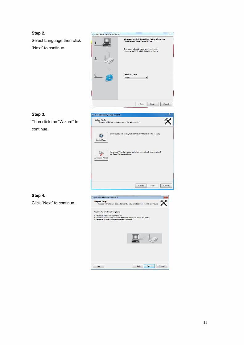
Step 2.
Select Language then click
“Next” to continue.
Step 3.
Then click the “Wizard” to
continue.
Step 4.
Click “Next” to continue.
12
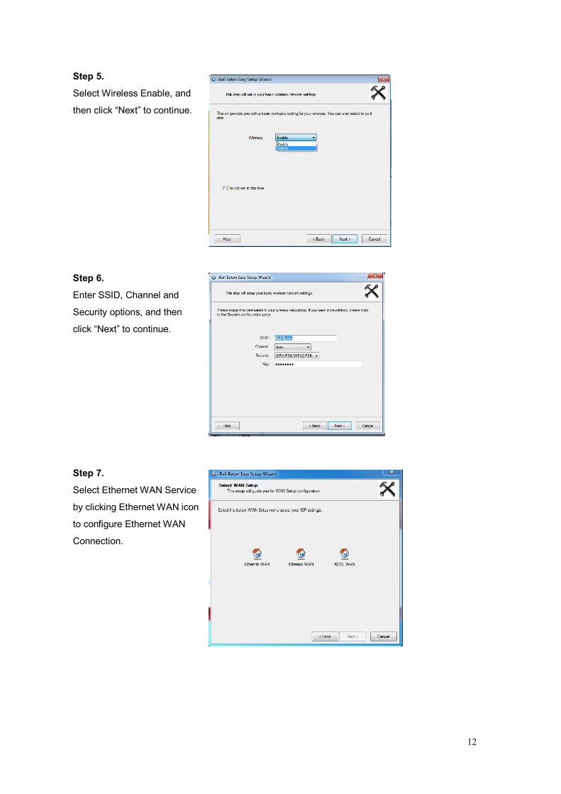
Step 5.
Select Wireless Enable, and
then click “Next” to continue.
Step 6.
Enter SSID, Channel and
Security options, and then
click “Next” to continue.
Step 7.
Select Ethernet WAN Service
by clicking Ethernet WAN icon
to configure Ethernet WAN
Connection.
13
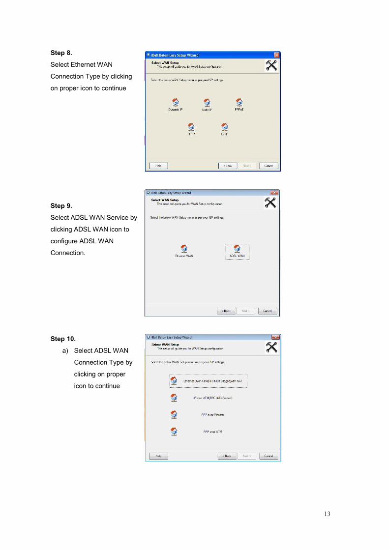
Step 8.
Select Ethernet WAN
Connection Type by clicking
on proper icon to continue
Step 9.
Select ADSL WAN Service by
clicking ADSL WAN icon to
configure ADSL WAN
Connection.
Step 10.
a) Select ADSL WAN
Connection Type by
clicking on proper
icon to continue
14
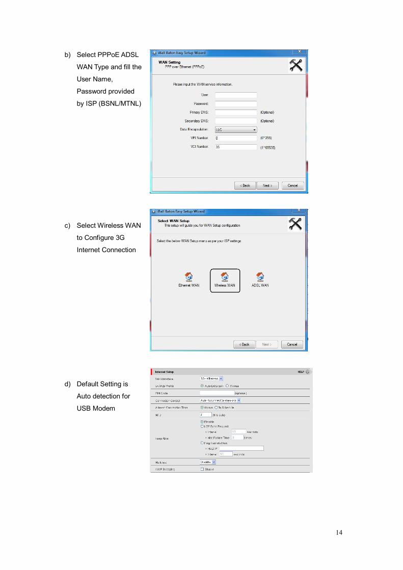
b) Select PPPoE ADSL
WAN Type and fill the
User Name,
Password provided
by ISP (BSNL/MTNL)
c) Select Wireless WAN
to Configure 3G
Internet Connection
d) Default Setting is
Auto detection for
USB Modem
15
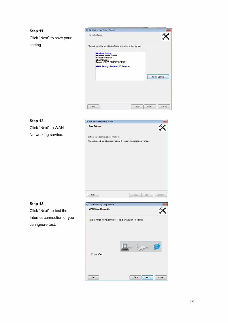
Step 11.
Click “Next” to save your
setting.
Step 12.
Click “Next” to WAN
Networking service.
Step 13.
Click “Next” to test the
Internet connection or you
can ignore test.
16
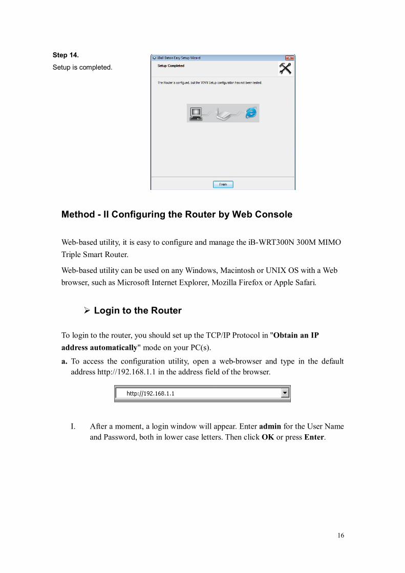
Step 14.
Setup is completed.
Method - II Configuring the Router by Web Console Web-based utility, it is easy to configure and manage the iB-WRT300N 300M MIMO Triple Smart Router.
Web-based utility can be used on any Windows, Macintosh or UNIX OS with a Web browser, such as Microsoft Internet Explorer, Mozilla Firefox or Apple Safari.
Login to the Router
To login to the router, you should set up the TCP/IP Protocol in "Obtain an IP address automatically" mode on your PC(s).
a. To access the configuration utility, open a web-browser and type in the default address http://192.168.1.1 in the address field of the browser.
I. After a moment, a login window will appear. Enter admin for the User Name and Password, both in lower case letters. Then click OK or press Enter.
17
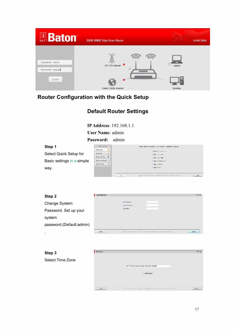
Router Configuration with the Quick Setup
Default Router Settings IP Address: 192.168.1.1 User Name: admin Password: admin
Step 1
Select Quick Setup for
Basic settings in a simple
way.
Step 2
Change System
Password. Set up your
system
password.(Default:admin)
.
Step 3
Select Time Zone
18
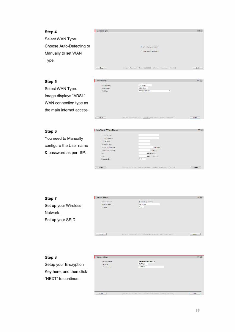
Step 4
Select WAN Type.
Choose Auto-Detecting or
Manually to set WAN
Type.
Step 5
Select WAN Type.
Image displays “ADSL”
WAN connection type as
the main internet access.
Step 6
You need to Manually
configure the User name
& password as per ISP.
Step 7
Set up your Wireless
Network.
Set up your SSID.
Step 8
Setup your Encryption
Key here, and then click
“NEXT” to continue.

19
Step 9
Apply your settings to
Continue.
Step 10
Click finish to Complete it.
Chapter 3 Router Configuration Whenever you want to configure your network or this device, you can access the Configuration
Menu by opening the web-browser and typing in the IP Address of the device.
The default IP Address is: 192.168.1.1.
Enter the default username “admin” and password “admin” and then click ‘login’ button.
Afterwards, you can go Quick Setup, Status Info, Network Setting, Advance Settings or
System Tools on left hand side of web page.
20
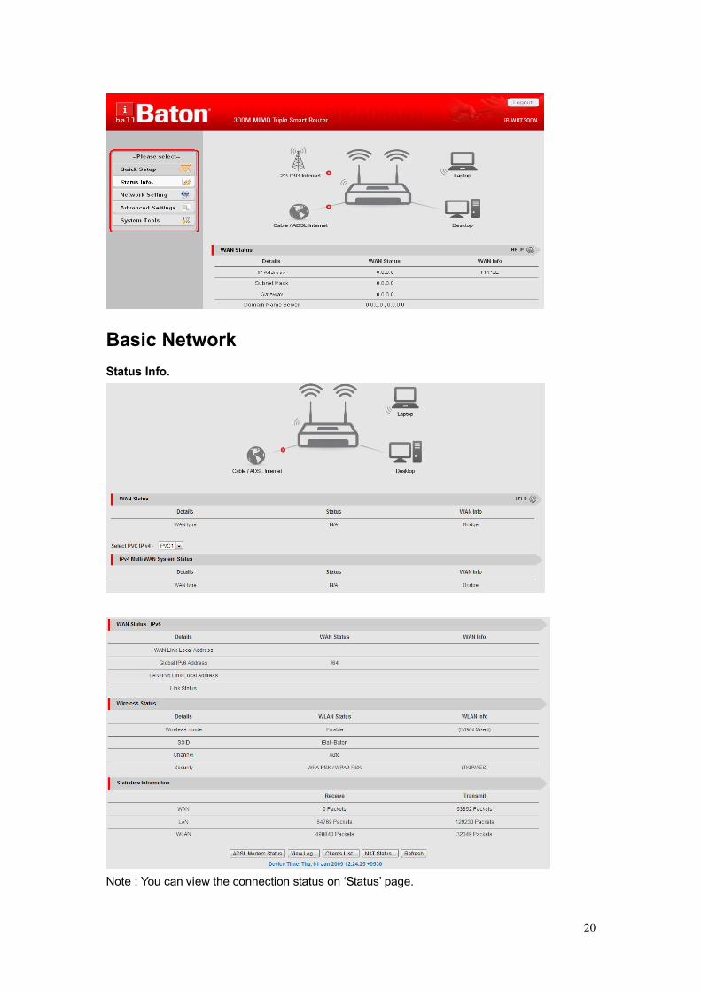
Basic Network Status Info.
Note : You can view the connection status on ‘Status’ page.

21
3.1.1 LAN & WAN Setup You can enter Network Setting, LAN / WAN / Wi-Fi for LAN and Internet setting as
below.
3.1.1.1 Network Setup Internet Setup
1. WAN Interface: You may select the following WAN type for your internet
connection
ADSL WAN Type: WAN connection type of your ISP. You can click WAN Type to choose
a correct one from the following options and select PVC0~7:
Ethernet Over ATM (RFC1483 Bridged) with NAT
IP over ATM(RFC 1483 Routed)
PPP over Ethernet
PPP over ATM
RFC 1483 Bridged
Multiple-PVC Summary table can list PVC0~7 for PVCs’ WAN type you selected.
Note: PVC0 = Main ADSL WAN
Default PVC Summary Table: VP/ VCI settings

22
A. Ethernet Over ATM(RFC1483 Bridged) with NAT
1. IP mode: select Dynamic IP address or Static IP address
2. Host Name: input your host name if you have one.
3. Connection Control: you can choose Connect-on-demand, Auto Reconnect
(always-on) and manually.
4. Maximum idle time : 600 seconds
5. NAT disable: If you enable this option, it will act with a non-NAT function.
6. Bridge mode: If you enable this option, it will act with a bridge mode for ADSL
function.
7. Data Encapsulation: Vc-MUX and LLC, these two options depend on your
ISP setting.
23
8. VPI and VCI, Schedule Type: these values depend on your ISP setting.
9. Schedule type: UBR / CBR / VBR / GFR, depend on your ISP setting.
10. Multicast: you may enable as auto mode or select by IGMP v1, IGMP v2 and
IGMP v3.
11. IGMP Snooping: enable or disable IGMP snooping function.
12. VLAN TAG: you may input the value of VLAN Tag by your ISP setting.
(Range : 1~4094)
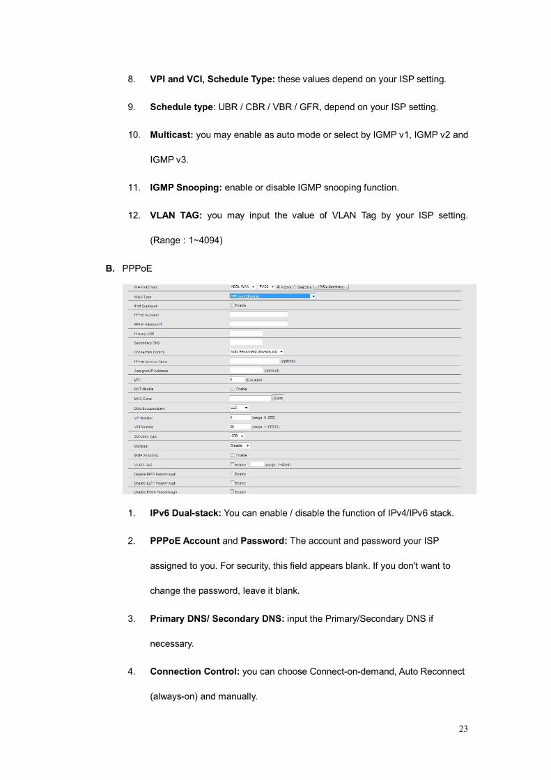
B. PPPoE
1. IPv6 Dual-stack: You can enable / disable the function of IPv4/IPv6 stack.
2. PPPoE Account and Password: The account and password your ISP
assigned to you. For security, this field appears blank. If you don't want to
change the password, leave it blank.
3. Primary DNS/ Secondary DNS: input the Primary/Secondary DNS if
necessary.
4. Connection Control: you can choose Connect-on-demand, Auto Reconnect
(always-on) and manually.

24
5. PPPoE Service name and assigned IP address: input the value if
necessary.
6. MTU: put all information here.
7. NAT disable: If you enable this option, it will act with a non-NAT function.
8. Bridge mode: If you enable this option, it will act with a bridge mode for ADSL
function.
9. Data Encapsulation: Vc-MUX and LLC, these two options depend on your
ISP setting.
10. VPI and VCI, Schedule Type: these values depend on your ISP setting.
11. Schedule type: UBR / CBR / VBR / GFR, depend on your ISP setting.
12. Multicast: you may enable as auto mode or select by IGMP v1, IGMP v2, and
IGMP v3.
13. IGMP Snooping: enable or disable IGMP snooping function.
14. VLAN TAG: you may input the value of VLAN Tag by your ISP setting.
(Range : 1~4094)

25
C. PPPoA
1. IPv6 Dual-stack: You can enable / disable the function of IPv4/IPv6 stack.
2. PPPoE Account and Password: The account and password your ISP
assigned to you. For security, this field appears blank. If you don't want to
change the password, leave it blank.
3. Primary DNS/ Secondary DNS: input the Primary/Secondary DNS if
necessary.
4. Connection Control: you can choose Connect-on-demand, Auto Reconnect
(always-on) and Manually.
5. PPPoE Service name and assigned IP address: input the value if
necessary.
6. MTU: put all information here.
7. NAT disable: If you enable this option, it will act with a non-NAT function.
8. Bridge mode: If you enable this option, it will act with a bridge mode for ADSL
function.

26
9. Data Encapsulation: Vc-MUX and LLC, these two options depend on your
ISP setting. (LLC is default as configured)
10. VPI and VCI, Schedule Type: these values depend on your ISP setting.
11. Schedule type: UBR / CBR / VBR / GFR, depend on your ISP setting.
12. Multicast: you may enable as auto mode or select by IGMP v1, IGMP v2, and
IGMP v3.
13. IGMP Snooping: enable or disable IGMP snooping function.
14. VLAN TAG: you may input the value of VLAN Tag by your ISP setting.
(Range : 1~4094)
Ethernet WAN A. Dynamic IP Address
1. Enable WWAN for Auto-Failover: With this function Enabled, Ethernet WAN
connection is broken, the device will automatically activate the Dual WAN connection
and keep you connected to internet with the alternative Dual WAN (2G/3G ISP service).
Meanwhile, if the device detected Ethernet WAN connection is recovered, your router
will switched to use the Ethernet WAN Internet connection service.
2. Host Name: Optional, required by some ISPs, Default : iB-WRT300N.
3. ISP registered MAC Address: Enter MAC address of your ISP. (Optional)
4. Connection Control: Connect-on-demand in the device will link up with ISP when
the clients send outgoing packets. Auto Reconnect (Always-on) in the device will link
27
with ISP until the connection is established. Manually mode in the device will not
make the link until someone clicks the connect-button in the Status-page.
5. NAT disable: If you enable this option, it will act with a non-NAT function.
6. Multicast: you may enable as auto mode or select by IGMP v1, IGMP v2, and IGMP
v3.
7. IGMP Snooping: enable or disable IGMP snooping function.
8. VLAN TAG: you may input the value of VLAN Tag by your ISP setting. (Range :
1~4094)
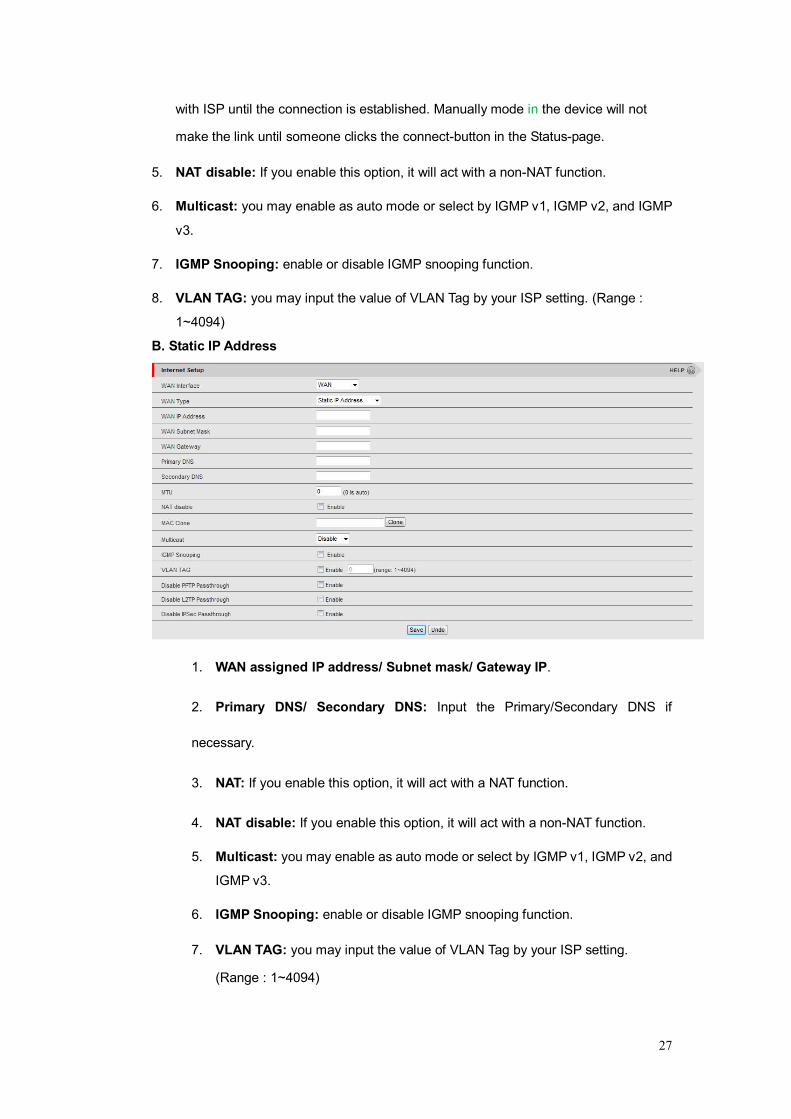
B. Static IP Address
1. WAN assigned IP address/ Subnet mask/ Gateway IP.
2. Primary DNS/ Secondary DNS: Input the Primary/Secondary DNS if
necessary.
3. NAT: If you enable this option, it will act with a NAT function.
4. NAT disable: If you enable this option, it will act with a non-NAT function.
5. Multicast: you may enable as auto mode or select by IGMP v1, IGMP v2, and
IGMP v3.
6. IGMP Snooping: enable or disable IGMP snooping function.
7. VLAN TAG: you may input the value of VLAN Tag by your ISP setting.
(Range : 1~4094)
28
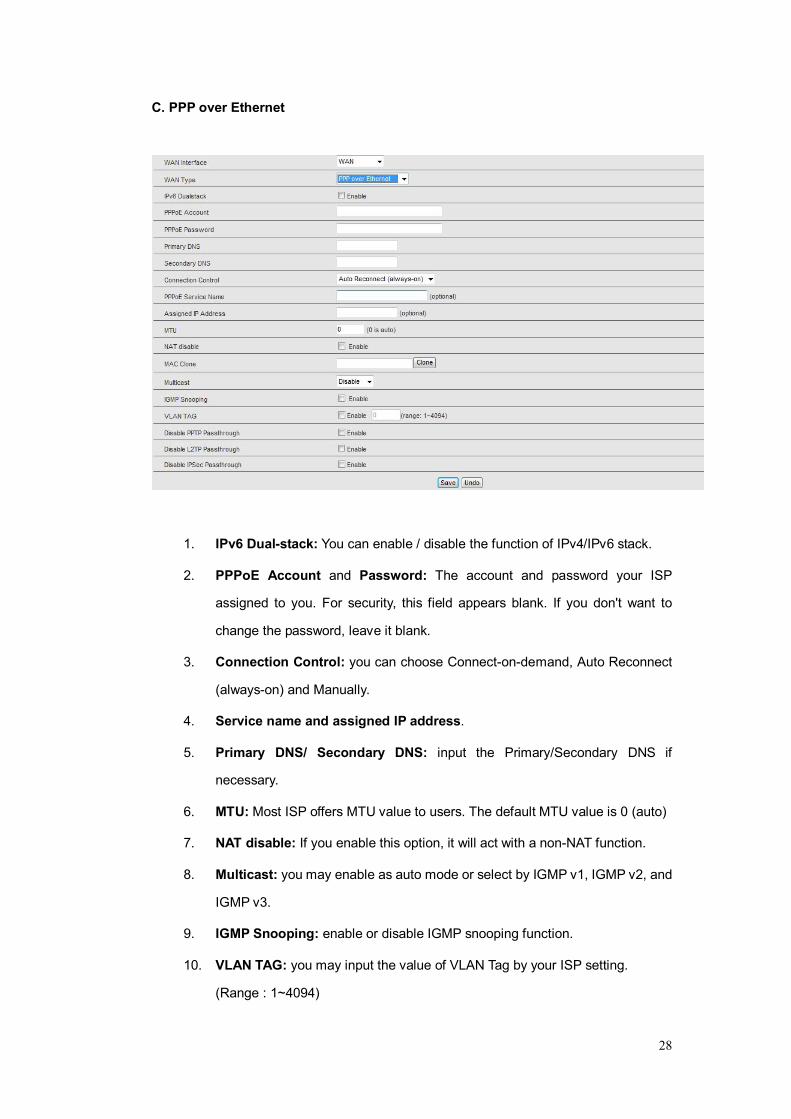
C. PPP over Ethernet
1. IPv6 Dual-stack: You can enable / disable the function of IPv4/IPv6 stack.
2. PPPoE Account and Password: The account and password your ISP
assigned to you. For security, this field appears blank. If you don't want to
change the password, leave it blank.
3. Connection Control: you can choose Connect-on-demand, Auto Reconnect
(always-on) and Manually.
4. Service name and assigned IP address.
5. Primary DNS/ Secondary DNS: input the Primary/Secondary DNS if
necessary.
6. MTU: Most ISP offers MTU value to users. The default MTU value is 0 (auto)
7. NAT disable: If you enable this option, it will act with a non-NAT function.
8. Multicast: you may enable as auto mode or select by IGMP v1, IGMP v2, and
IGMP v3.
9. IGMP Snooping: enable or disable IGMP snooping function.
10. VLAN TAG: you may input the value of VLAN Tag by your ISP setting.
(Range : 1~4094)
29
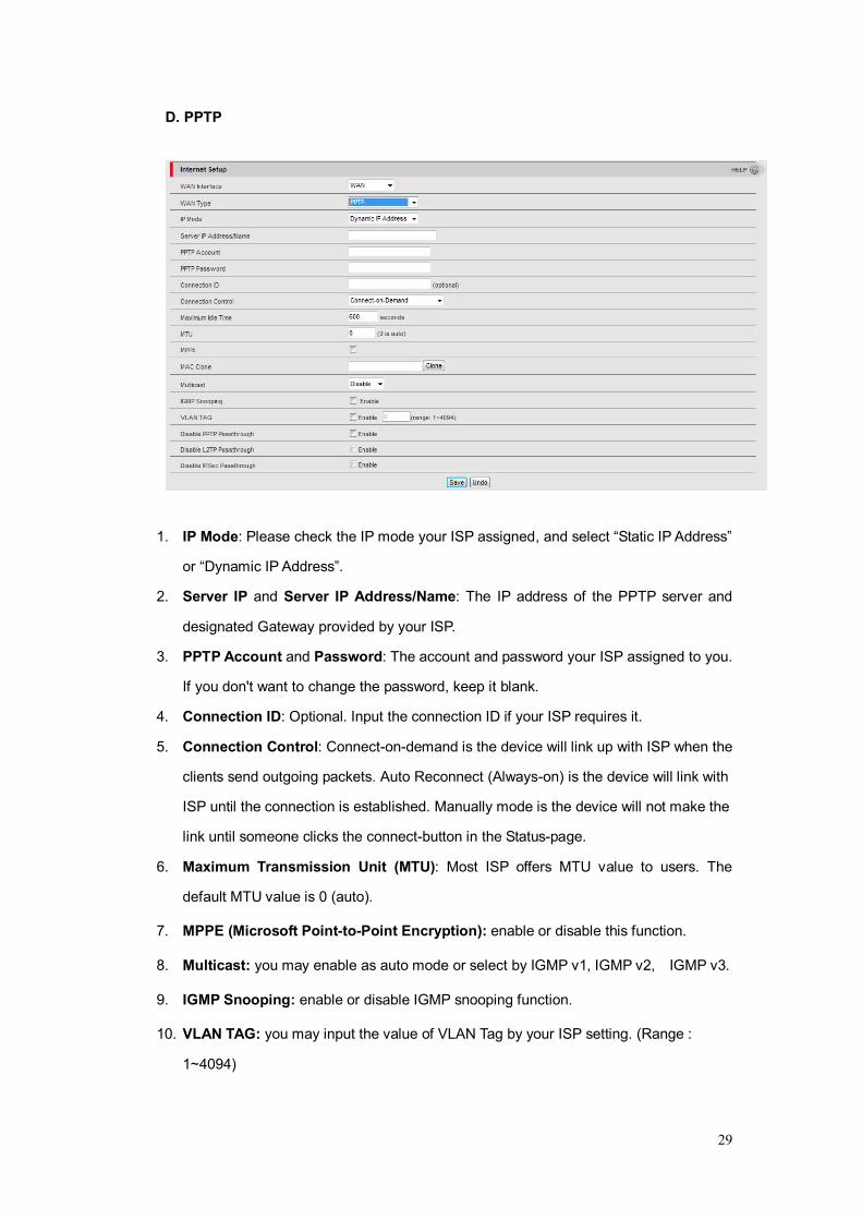
D. PPTP
1. IP Mode: Please check the IP mode your ISP assigned, and select “Static IP Address”
or “Dynamic IP Address”.
2. Server IP and Server IP Address/Name: The IP address of the PPTP server and
designated Gateway provided by your ISP.
3. PPTP Account and Password: The account and password your ISP assigned to you.
If you don't want to change the password, keep it blank.
4. Connection ID: Optional. Input the connection ID if your ISP requires it.
5. Connection Control: Connect-on-demand is the device will link up with ISP when the
clients send outgoing packets. Auto Reconnect (Always-on) is the device will link with
ISP until the connection is established. Manually mode is the device will not make the
link until someone clicks the connect-button in the Status-page.
6. Maximum Transmission Unit (MTU): Most ISP offers MTU value to users. The
default MTU value is 0 (auto).
7. MPPE (Microsoft Point-to-Point Encryption): enable or disable this function.
8. Multicast: you may enable as auto mode or select by IGMP v1, IGMP v2, IGMP v3.
9. IGMP Snooping: enable or disable IGMP snooping function.
10. VLAN TAG: you may input the value of VLAN Tag by your ISP setting. (Range :
1~4094)
30
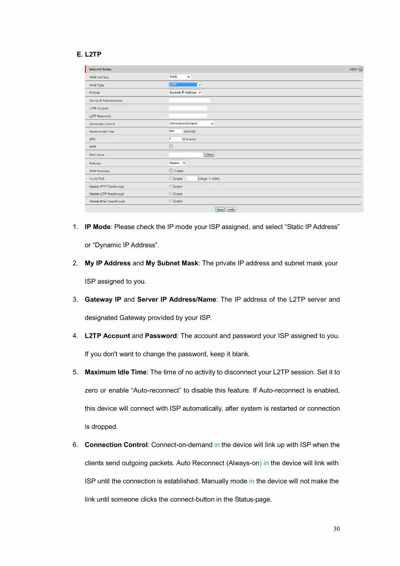
E. L2TP
1. IP Mode: Please check the IP mode your ISP assigned, and select “Static IP Address”
or “Dynamic IP Address”.
2. My IP Address and My Subnet Mask: The private IP address and subnet mask your
ISP assigned to you.
3. Gateway IP and Server IP Address/Name: The IP address of the L2TP server and
designated Gateway provided by your ISP.
4. L2TP Account and Password: The account and password your ISP assigned to you.
If you don't want to change the password, keep it blank.
5. Maximum Idle Time: The time of no activity to disconnect your L2TP session. Set it to
zero or enable “Auto-reconnect” to disable this feature. If Auto-reconnect is enabled,
this device will connect with ISP automatically, after system is restarted or connection
is dropped.
6. Connection Control: Connect-on-demand in the device will link up with ISP when the
clients send outgoing packets. Auto Reconnect (Always-on) in the device will link with
ISP until the connection is established. Manually mode in the device will not make the
link until someone clicks the connect-button in the Status-page.
31
7. Maximum Transmission Unit (MTU): Most ISP offers MTU value to users. The
default MTU value is 0 (auto).
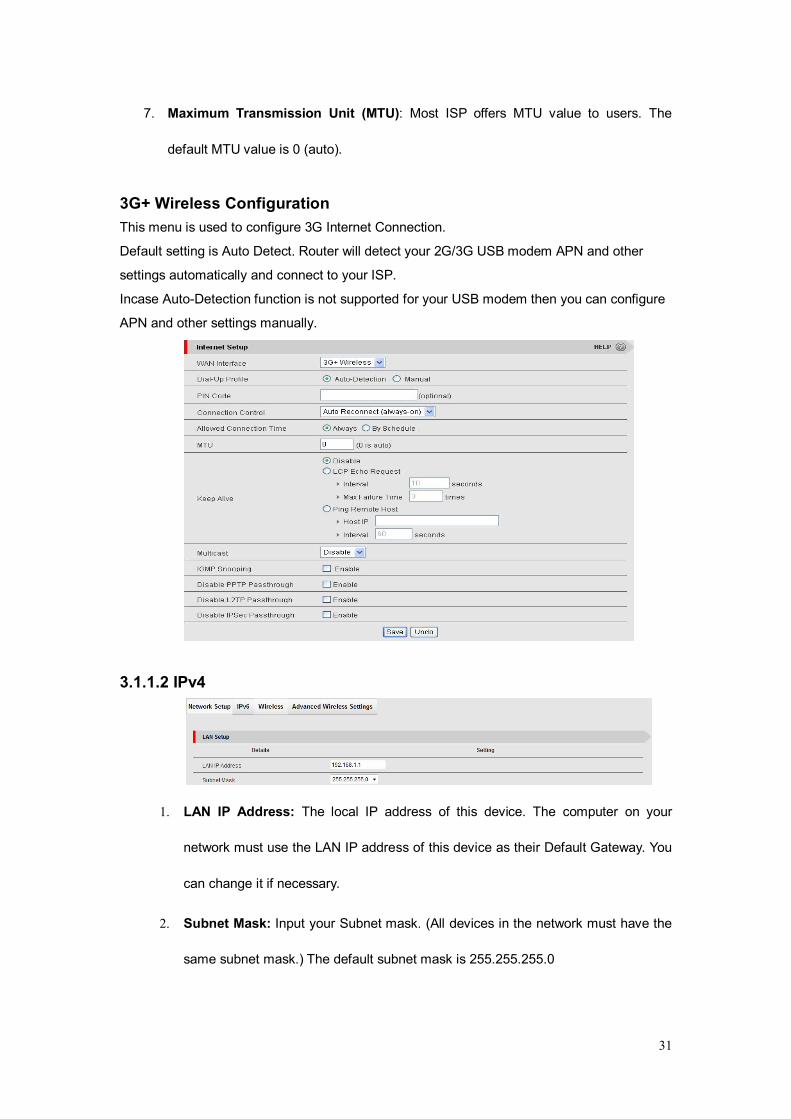
3G+ Wireless Configuration This menu is used to configure 3G Internet Connection.
Default setting is Auto Detect. Router will detect your 2G/3G USB modem APN and other
settings automatically and connect to your ISP.
Incase Auto-Detection function is not supported for your USB modem then you can configure
APN and other settings manually.
3.1.1.2 IPv4
1. LAN IP Address: The local IP address of this device. The computer on your
network must use the LAN IP address of this device as their Default Gateway. You
can change it if necessary.
2. Subnet Mask: Input your Subnet mask. (All devices in the network must have the
same subnet mask.) The default subnet mask is 255.255.255.0
32
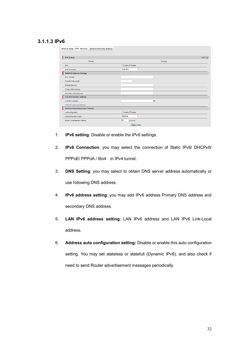
3.1.1.3 IPv6
1. IPv6 setting: Disable or enable the IPv6 settings.
2. IPv6 Connection: you may select the connection of Static IPv6/ DHCPv6/
PPPoE/ PPPoA / 6to4 in IPv4 tunnel.
3. DNS Setting: you may select to obtain DNS server address automatically or
use following DNS address.
4. IPv6 address setting: you may add IPv6 address Primary DNS address and
secondary DNS address.
5. LAN IPv6 address setting: LAN IPv6 address and LAN IPv6 Link-Local
address.
6. Address auto configuration setting: Disable or enable this auto configuration
setting. You may set stateless or statefull (Dynamic IPv6), and also check if
need to send Router advertisement messages periodically.
33
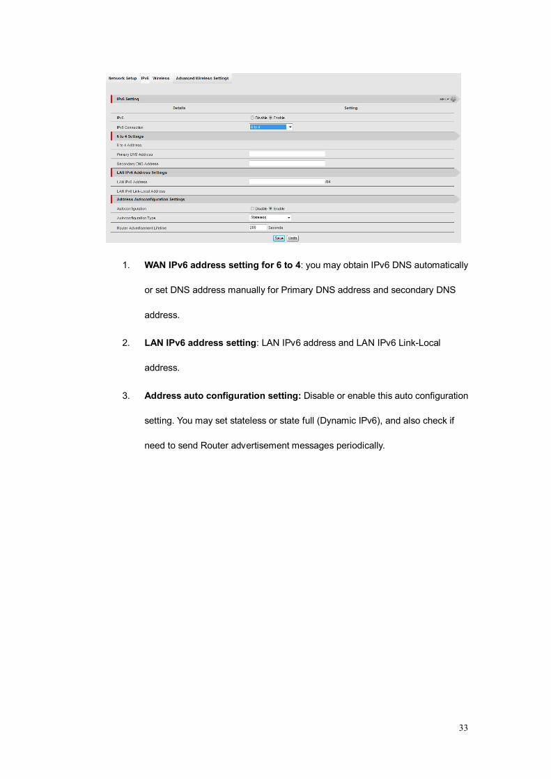
1. WAN IPv6 address setting for 6 to 4: you may obtain IPv6 DNS automatically
or set DNS address manually for Primary DNS address and secondary DNS
address.
2. LAN IPv6 address setting: LAN IPv6 address and LAN IPv6 Link-Local
address.
3. Address auto configuration setting: Disable or enable this auto configuration
setting. You may set stateless or state full (Dynamic IPv6), and also check if
need to send Router advertisement messages periodically.
34
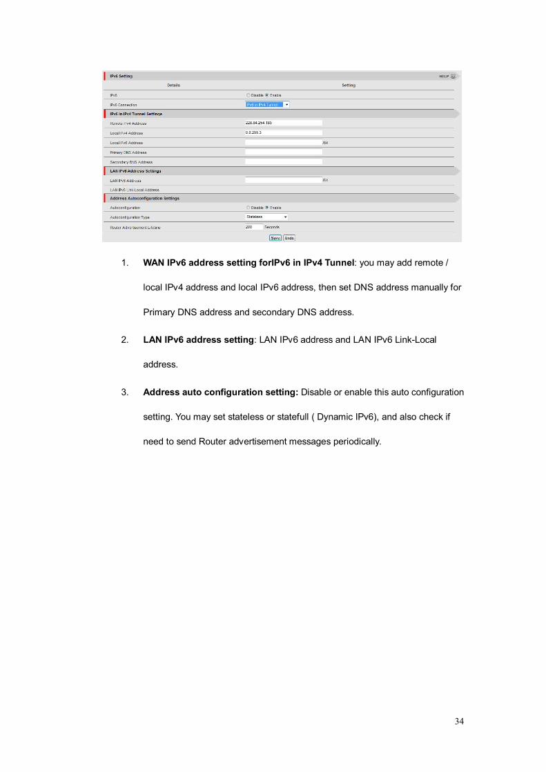
1. WAN IPv6 address setting forIPv6 in IPv4 Tunnel: you may add remote /
local IPv4 address and local IPv6 address, then set DNS address manually for
Primary DNS address and secondary DNS address.
2. LAN IPv6 address setting: LAN IPv6 address and LAN IPv6 Link-Local
address.
3. Address auto configuration setting: Disable or enable this auto configuration
setting. You may set stateless or statefull ( Dynamic IPv6), and also check if
need to send Router advertisement messages periodically.

35
3.1.1.4 Wireless Settings
AP Router Mode
“AP Router Mode” With this function user can configure the Internet as per WAN
connection type & Access Internet through Wi-Fi as well as wired.
AP Mode
“AP Only mode” With this function Access point acts as a central transmitter and receiver
of WLAN radio signals.
36
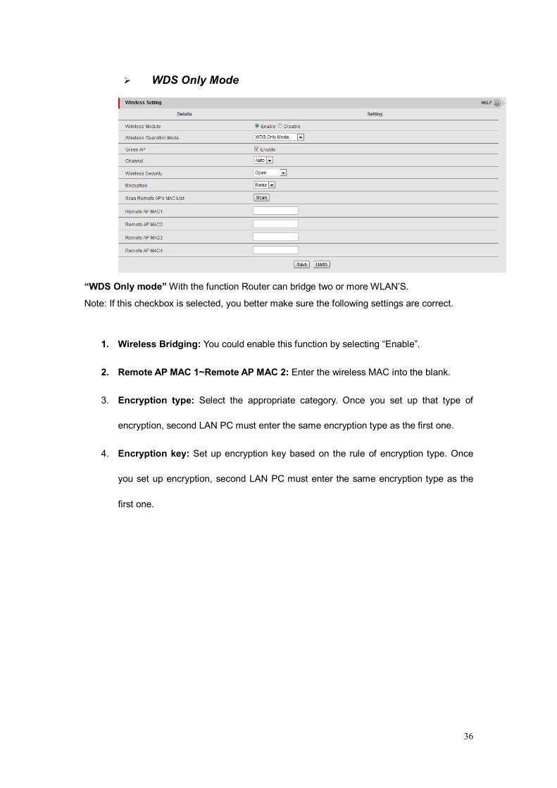
WDS Only Mode
“WDS Only mode” With the function Router can bridge two or more WLAN’S.
Note: If this checkbox is selected, you better make sure the following settings are correct.
1. Wireless Bridging: You could enable this function by selecting “Enable”.
2. Remote AP MAC 1~Remote AP MAC 2: Enter the wireless MAC into the blank.
3. Encryption type: Select the appropriate category. Once you set up that type of
encryption, second LAN PC must enter the same encryption type as the first one.
4. Encryption key: Set up encryption key based on the rule of encryption type. Once
you set up encryption, second LAN PC must enter the same encryption type as the
first one.
37
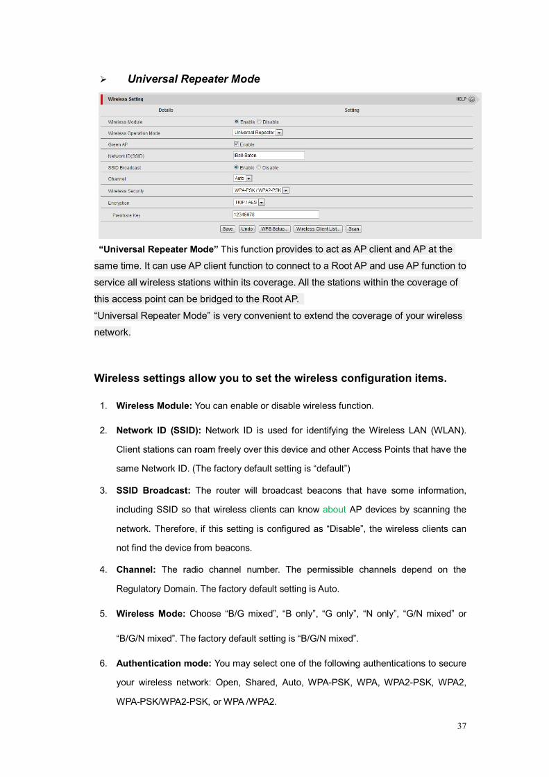
Universal Repeater Mode
“Universal Repeater Mode” This function provides to act as AP client and AP at the
same time. It can use AP client function to connect to a Root AP and use AP function to
service all wireless stations within its coverage. All the stations within the coverage of
this access point can be bridged to the Root AP.
“Universal Repeater Mode” is very convenient to extend the coverage of your wireless
network.
Wireless settings allow you to set the wireless configuration items.
1. Wireless Module: You can enable or disable wireless function.
2. Network ID (SSID): Network ID is used for identifying the Wireless LAN (WLAN).
Client stations can roam freely over this device and other Access Points that have the
same Network ID. (The factory default setting is “default”)
3. SSID Broadcast: The router will broadcast beacons that have some information,
including SSID so that wireless clients can know about AP devices by scanning the
network. Therefore, if this setting is configured as “Disable”, the wireless clients can
not find the device from beacons.
4. Channel: The radio channel number. The permissible channels depend on the
Regulatory Domain. The factory default setting is Auto.
5. Wireless Mode: Choose “B/G mixed”, “B only”, “G only”, “N only”, “G/N mixed” or
“B/G/N mixed”. The factory default setting is “B/G/N mixed”.
6. Authentication mode: You may select one of the following authentications to secure
your wireless network: Open, Shared, Auto, WPA-PSK, WPA, WPA2-PSK, WPA2,
WPA-PSK/WPA2-PSK, or WPA /WPA2.

38
Open
Open system authentication simply consists of two communications. The first is an
authentication request by the client that contains the station ID (typically the MAC
address). This is followed by an authentication response from the AP/router containing
a success or failure message. An example of when a failure may occur is if the client's
MAC address is explicitly excluded in the AP/router configuration.
Shared
Shared key authentication relies on the fact that both stations taking part in the
authentication process have the same "shared" key or passphrase. The shared key is
manually set on both the client station and the AP/router. Three types of shared key
authentication are available today for home or small office WLAN environments.
Auto
The AP will Select the Open or Shared by the client’s request automatically.
WPA-PSK
Select Encryption and Pre-shared Key Mode
If you select HEX, you have to fill in 64 hexadecimal (0, 1, 2…8, 9, A, B…F) digits.
If you select ASCII, the length of pre-shared key is from 8 to 63.
Fill in the key, Ex 12345678
WPA
Check Box was used to switch the function of the WPA. When the WPA function is
enabled, the Wireless user must authenticate to this router first to use the Network
service. RADIUS Server IP address or the 802.1X server’s domain-name.
Select Encryption and RADIUS Shared Key.
If you select HEX, you have to fill in 64 hexadecimal (0, 1, 2…8, 9, A, B…F) digits.
If you select ASCII, the length of pre-share key is from 8 to 63.
Key value shared by the RADIUS server and this router. This key value is consistent
with the key value in the RADIUS server.
WPA2-PSK
WPA2-PSK user AES and TKIP for Same the encryption, the others are same as the
WPA2-PSK.
WPA-PSK/WPA2-PSK
Another encryption options for WPA-PSK-TKIP and WPA2-PSK-AES, the others are
same as the WPA-PSK.
WPA/WPA2
Another encryption options for WPA-TKIP and WPA2-AES, the others are same as the
WPA.
39
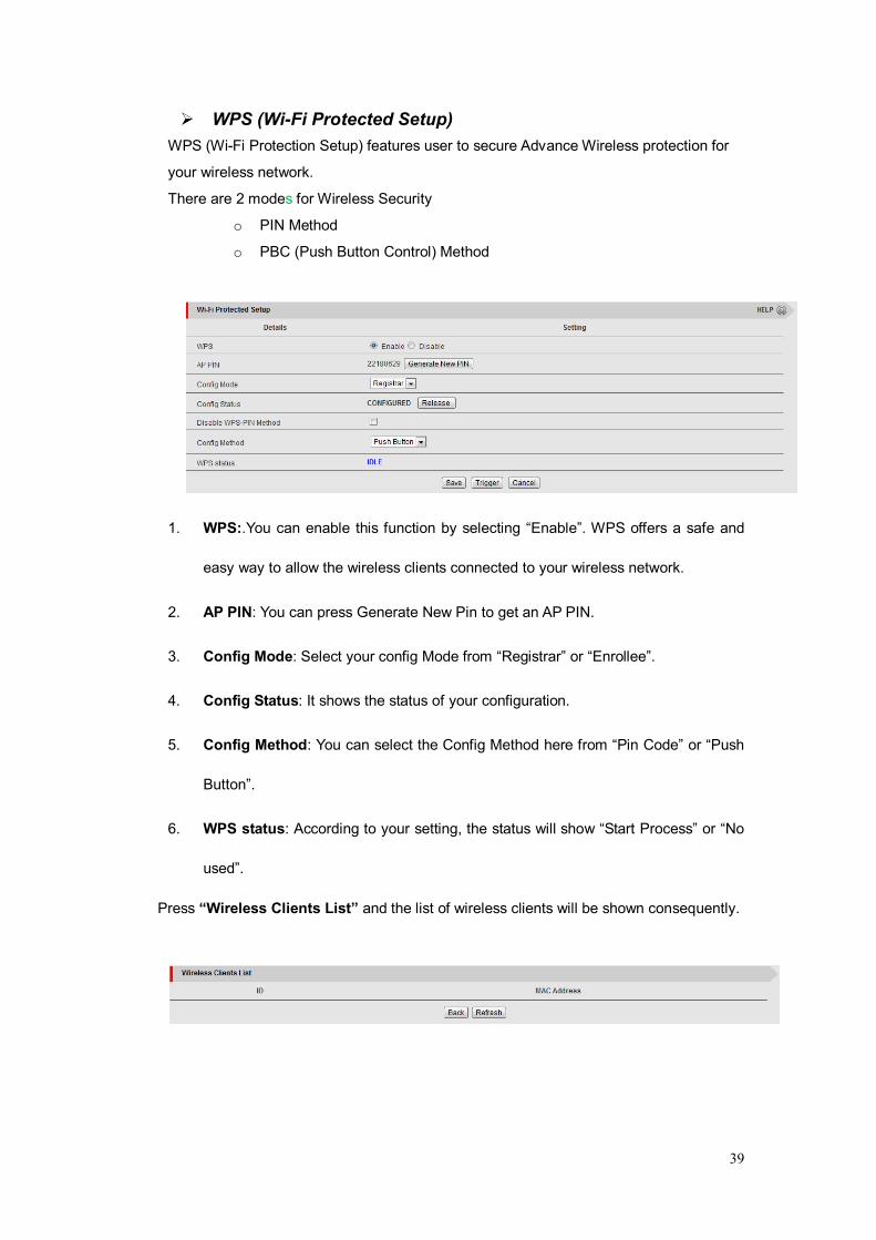
WPS (Wi-Fi Protected Setup) WPS (Wi-Fi Protection Setup) features user to secure Advance Wireless protection for
your wireless network.
There are 2 modes for Wireless Security
o PIN Method
o PBC (Push Button Control) Method
1. WPS:.You can enable this function by selecting “Enable”. WPS offers a safe and
easy way to allow the wireless clients connected to your wireless network.
2. AP PIN: You can press Generate New Pin to get an AP PIN.
3. Config Mode: Select your config Mode from “Registrar” or “Enrollee”.
4. Config Status: It shows the status of your configuration.
5. Config Method: You can select the Config Method here from “Pin Code” or “Push
Button”.
6. WPS status: According to your setting, the status will show “Start Process” or “No
used”.
Press “Wireless Clients List” and the list of wireless clients will be shown consequently.
40
3.1.2 Forwarding
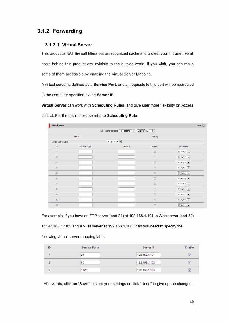
3.1.2.1 Virtual Server
This product’s NAT firewall filters out unrecognized packets to protect your Intranet, so all
hosts behind this product are invisible to the outside world. If you wish, you can make
some of them accessible by enabling the Virtual Server Mapping.
A virtual server is defined as a Service Port, and all requests to this port will be redirected
to the computer specified by the Server IP.
Virtual Server can work with Scheduling Rules, and give user more flexibility on Access
control. For the details, please refer to Scheduling Rule.
For example, if you have an FTP server (port 21) at 192.168.1.101, a Web server (port 80)
at 192.168.1.102, and a VPN server at 192.168.1.106, then you need to specify the
following virtual server mapping table:
Afterwards, click on “Save” to store your settings or click “Undo” to give up the changes.
41
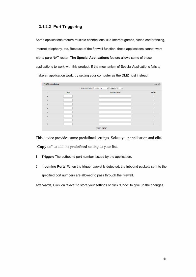
3.1.2.2 Port Triggering
Some applications require multiple connections, like Internet games, Video conferencing,
Internet telephony, etc. Because of the firewall function, these applications cannot work
with a pure NAT router. The Special Applications feature allows some of these
applications to work with this product. If the mechanism of Special Applications fails to
make an application work, try setting your computer as the DMZ host instead.
This device provides some predefined settings. Select your application and click
“Copy to” to add the predefined setting to your list.
1. Trigger: The outbound port number issued by the application.
2. Incoming Ports: When the trigger packet is detected, the inbound packets sent to the
specified port numbers are allowed to pass through the firewall.
Afterwards, Click on “Save” to store your settings or click “Undo” to give up the changes.
42
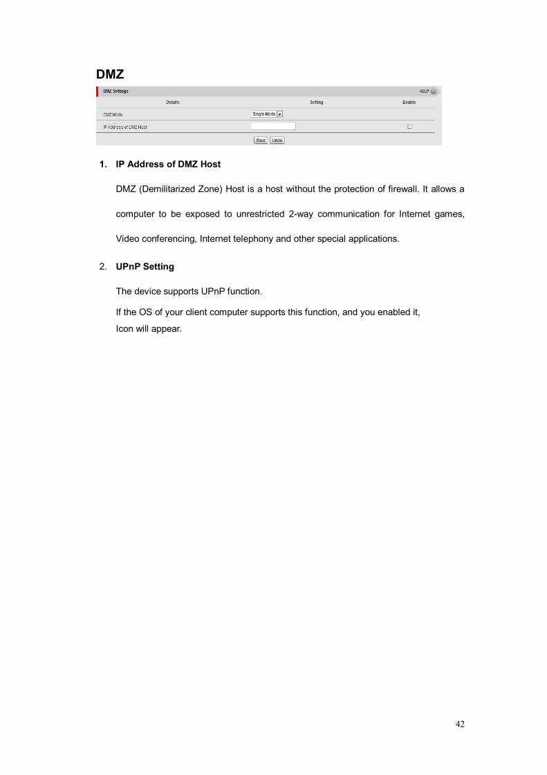
DMZ
1. IP Address of DMZ Host
DMZ (Demilitarized Zone) Host is a host without the protection of firewall. It allows a
computer to be exposed to unrestricted 2-way communication for Internet games,
Video conferencing, Internet telephony and other special applications.
2. UPnP Setting
The device supports UPnP function.
If the OS of your client computer supports this function, and you enabled it,
Icon will appear.
43
3.1.3 Routing
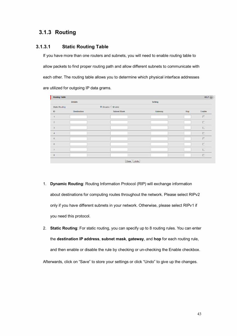
3.1.3.1 Static Routing Table
If you have more than one routers and subnets, you will need to enable routing table to
allow packets to find proper routing path and allow different subnets to communicate with
each other. The routing table allows you to determine which physical interface addresses
are utilized for outgoing IP data grams.
1. Dynamic Routing: Routing Information Protocol (RIP) will exchange information
about destinations for computing routes throughout the network. Please select RIPv2
only if you have different subnets in your network. Otherwise, please select RIPv1 if
you need this protocol.
2. Static Routing: For static routing, you can specify up to 8 routing rules. You can enter
the destination IP address, subnet mask, gateway, and hop for each routing rule,
and then enable or disable the rule by checking or un-checking the Enable checkbox.
Afterwards, click on “Save” to store your settings or click “Undo” to give up the changes.

44
3.1.4 Change Password
You can change the System Password here. We strongly recommend you to change the
system password for security reason. Click on “Save” to store your settings.
3.1.4 DHCP & Dyndns Setting
3.1.4.1 DHCP Server
1. DHCP Server: Choose either Disable or Enable. If you enable the DHCP Server
function, the following settings will be effective.
2. IP Pool Starting/Ending Address: Whenever there is a request, the DHCP server
will automatically allocate an unused IP address from the IP address pool to the
requesting computer. You must specify the starting / ending address of the IP address
pool.
3. Lease Time: DHCP lease time to the DHCP client.
4. Domain Name: Optional, this information will be passed to the clients.

45
Press “More>>” and you can find more settings.
5. Primary DNS/Secondary DNS: Optional. This feature allows you to assign a DNS
Servers
6. Primary WINS/Secondary WINS: Optional. This feature allows you to assign a WINS
Servers
7. Gateway: Optional. Gateway Address would be the IP address of an alternate
Gateway. This function enables you to assign another gateway to your PC, when
DHCP server offers an IP to your PC.
Press “Clients List” and the list of DHCP clients will be shown consequently.
Press “Fixed Mapping” and the DHCP Server will reserve the special IP for designated
MAC address.
46
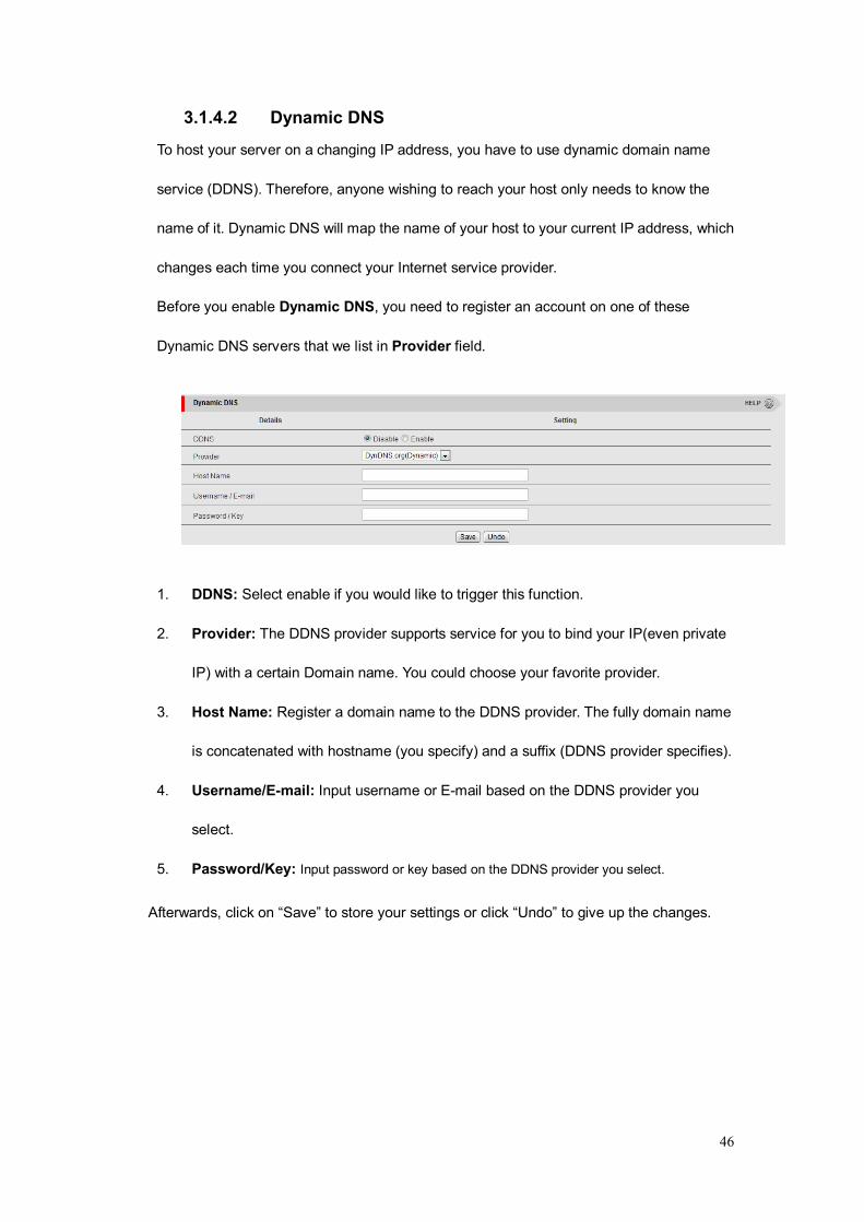
3.1.4.2 Dynamic DNS
To host your server on a changing IP address, you have to use dynamic domain name
service (DDNS). Therefore, anyone wishing to reach your host only needs to know the
name of it. Dynamic DNS will map the name of your host to your current IP address, which
changes each time you connect your Internet service provider.
Before you enable Dynamic DNS, you need to register an account on one of these
Dynamic DNS servers that we list in Provider field.
1. DDNS: Select enable if you would like to trigger this function.
2. Provider: The DDNS provider supports service for you to bind your IP(even private
IP) with a certain Domain name. You could choose your favorite provider.
3. Host Name: Register a domain name to the DDNS provider. The fully domain name
is concatenated with hostname (you specify) and a suffix (DDNS provider specifies).
4. Username/E-mail: Input username or E-mail based on the DDNS provider you
select.
5. Password/Key: Input password or key based on the DDNS provider you select.
Afterwards, click on “Save” to store your settings or click “Undo” to give up the changes.
47
3.2. Advance Settings
3.2.1. Security Settings
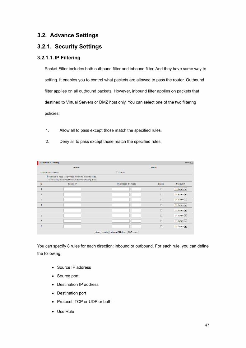
3.2.1.1. IP Filtering
Packet Filter includes both outbound filter and inbound filter. And they have same way to
setting. It enables you to control what packets are allowed to pass the router. Outbound
filter applies on all outbound packets. However, inbound filter applies on packets that
destined to Virtual Servers or DMZ host only. You can select one of the two filtering
policies:
1. Allow all to pass except those match the specified rules.
2. Deny all to pass except those match the specified rules.
You can specify 8 rules for each direction: inbound or outbound. For each rule, you can define
the following:
Source IP address
Source port
Destination IP address
Destination port
Protocol: TCP or UDP or both.
Use Rule
48
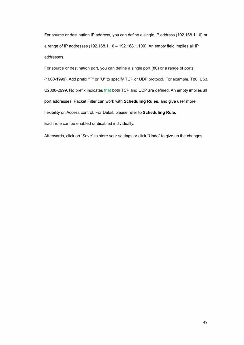
For source or destination IP address, you can define a single IP address (192.168.1.10) or
a range of IP addresses (192.168.1.10 – 192.168.1.100). An empty field implies all IP
addresses.
For source or destination port, you can define a single port (80) or a range of ports
(1000-1999). Add prefix "T" or "U" to specify TCP or UDP protocol. For example, T80, U53,
U2000-2999, No prefix indicates that both TCP and UDP are defined. An empty implies all
port addresses. Packet Filter can work with Scheduling Rules, and give user more
flexibility on Access control. For Detail, please refer to Scheduling Rule.
Each rule can be enabled or disabled individually.
Afterwards, click on “Save” to store your settings or click “Undo” to give up the changes.
49
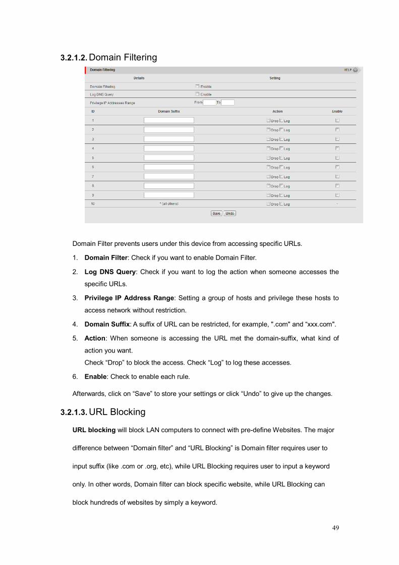
3.2.1.2. Domain Filtering
Domain Filter prevents users under this device from accessing specific URLs.
1. Domain Filter: Check if you want to enable Domain Filter.
2. Log DNS Query: Check if you want to log the action when someone accesses the
specific URLs.
3. Privilege IP Address Range: Setting a group of hosts and privilege these hosts to
access network without restriction.
4. Domain Suffix: A suffix of URL can be restricted, for example, ".com" and “xxx.com".
5. Action: When someone is accessing the URL met the domain-suffix, what kind of
action you want.
Check “Drop” to block the access. Check “Log” to log these accesses.
6. Enable: Check to enable each rule.
Afterwards, click on “Save” to store your settings or click “Undo” to give up the changes.
3.2.1.3. URL Blocking URL blocking will block LAN computers to connect with pre-define Websites. The major
difference between “Domain filter” and “URL Blocking” is Domain filter requires user to
input suffix (like .com or .org, etc), while URL Blocking requires user to input a keyword
only. In other words, Domain filter can block specific website, while URL Blocking can
block hundreds of websites by simply a keyword.
50
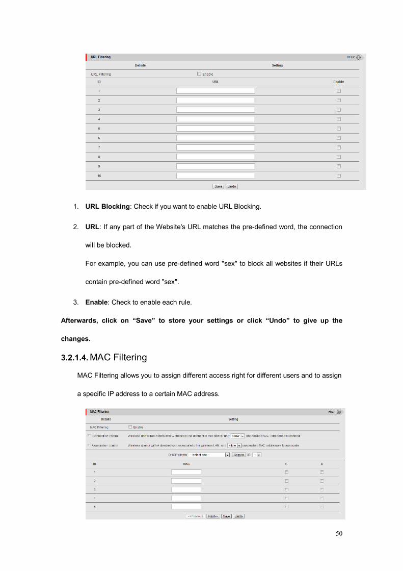
1. URL Blocking: Check if you want to enable URL Blocking.
2. URL: If any part of the Website's URL matches the pre-defined word, the connection
will be blocked.
For example, you can use pre-defined word "sex" to block all websites if their URLs
contain pre-defined word "sex".
3. Enable: Check to enable each rule.
Afterwards, click on “Save” to store your settings or click “Undo” to give up the
changes.
3.2.1.4. MAC Filtering MAC Filtering allows you to assign different access right for different users and to assign
a specific IP address to a certain MAC address.
51
1. MAC Address Control: Check “Enable” to enable the “MAC Address Control”. All of
the settings in this page will take effect only when “Enable” is checked.
2. Connection control: Check "Connection control" to enable the controlling of which
wired and wireless clients can connect with this device. If a client is denied to connect
with this device, it means the client can't access to the Internet either. Choose "allow"
or "deny" to allow or deny the clients, whose MAC addresses are not in the "Control
table" (please see below), to connect with this device.
3. Association control: Check "Association control" to enable the controlling of
Which wireless client can associate to the wireless LAN. If a client is denied to
associate to the wireless LAN, it means the client can't send or receive any data via
this device. Choose "allow" or "deny" to allow or deny the clients, whose MAC
addresses are not in the "Control table", to associate to the wireless LAN.
Afterwards, click on “Save” to store your settings.
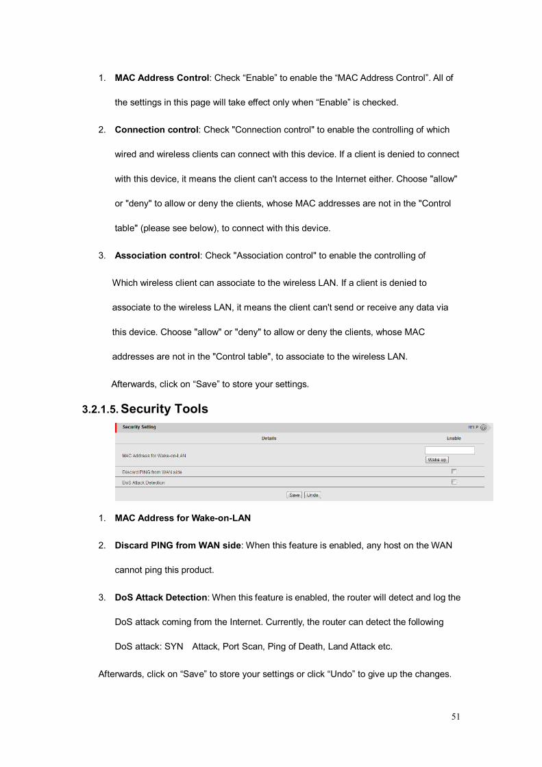
3.2.1.5. Security Tools
1. MAC Address for Wake-on-LAN
2. Discard PING from WAN side: When this feature is enabled, any host on the WAN
cannot ping this product.
3. DoS Attack Detection: When this feature is enabled, the router will detect and log the
DoS attack coming from the Internet. Currently, the router can detect the following
DoS attack: SYN Attack, Port Scan, Ping of Death, Land Attack etc.
Afterwards, click on “Save” to store your settings or click “Undo” to give up the changes.
52
3.2.2. QoS
Quality of service is the ability to provide different priority to different applications, users, or
data flows, or to guarantee a certain level of performance to a data flow.
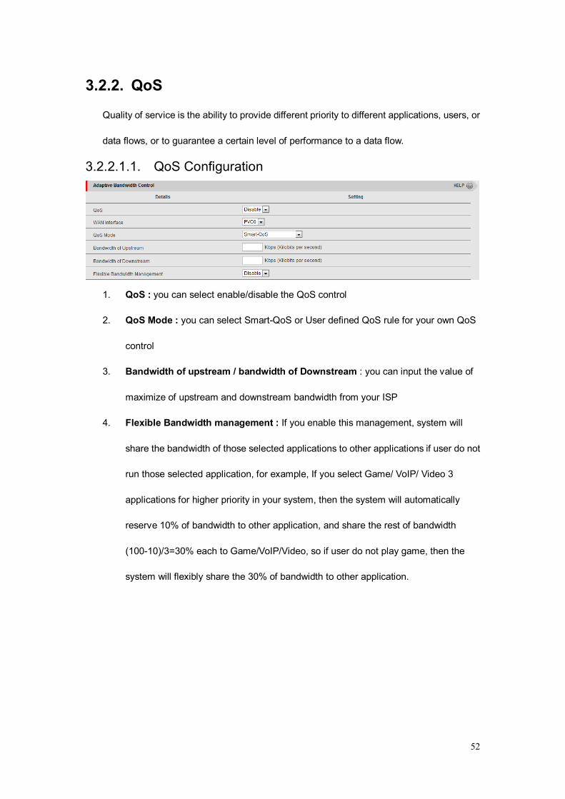
3.2.2.1.1. QoS Configuration
1. QoS : you can select enable/disable the QoS control
2. QoS Mode : you can select Smart-QoS or User defined QoS rule for your own QoS
control
3. Bandwidth of upstream / bandwidth of Downstream : you can input the value of
maximize of upstream and downstream bandwidth from your ISP
4. Flexible Bandwidth management : If you enable this management, system will
share the bandwidth of those selected applications to other applications if user do not
run those selected application, for example, If you select Game/ VoIP/ Video 3
applications for higher priority in your system, then the system will automatically
reserve 10% of bandwidth to other application, and share the rest of bandwidth
(100-10)/3=30% each to Game/VoIP/Video, so if user do not play game, then the
system will flexibly share the 30% of bandwidth to other application.
53
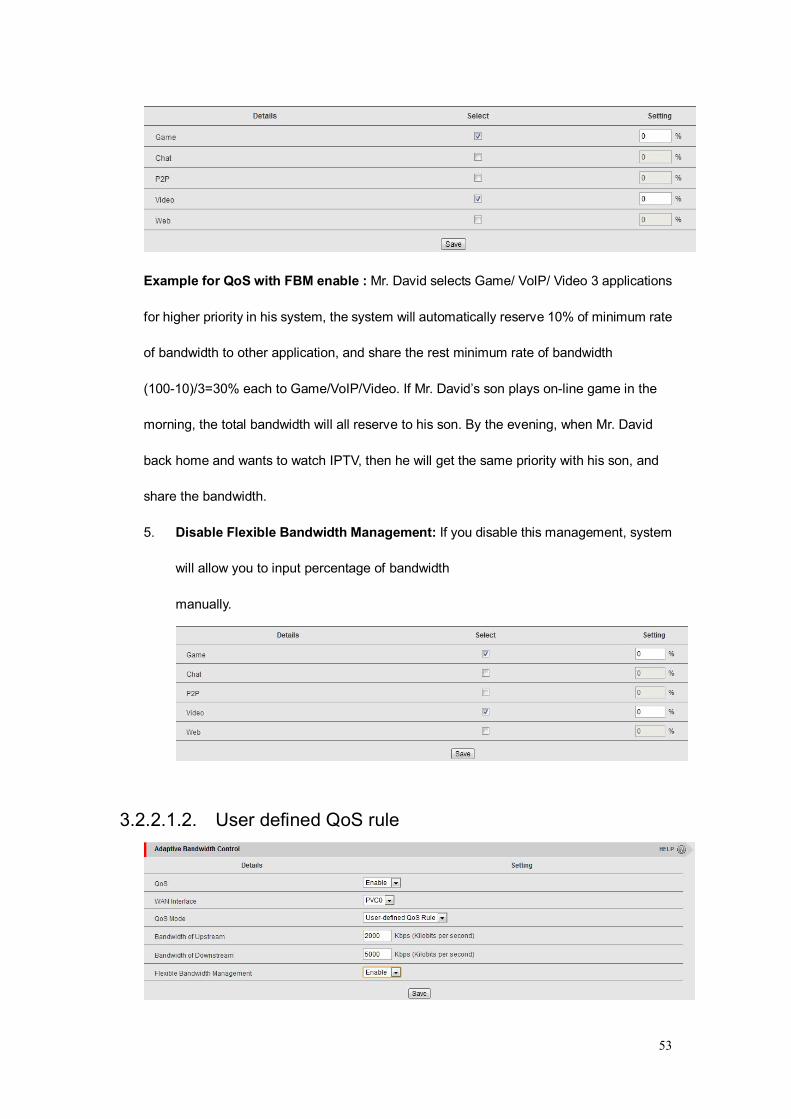
Example for QoS with FBM enable : Mr. David selects Game/ VoIP/ Video 3 applications
for higher priority in his system, the system will automatically reserve 10% of minimum rate
of bandwidth to other application, and share the rest minimum rate of bandwidth
(100-10)/3=30% each to Game/VoIP/Video. If Mr. David’s son plays on-line game in the
morning, the total bandwidth will all reserve to his son. By the evening, when Mr. David
back home and wants to watch IPTV, then he will get the same priority with his son, and
share the bandwidth.
5. Disable Flexible Bandwidth Management: If you disable this management, system
will allow you to input percentage of bandwidth
manually.
3.2.2.1.2. User defined QoS rule

54
1. Cross-layer QoS: you can enable/disable this QoS system.
2. QoS Mode : you can select User defined QoS rule for your own QoS control
3. Bandwidth of upstream / bandwidth of Downstream : you can input the value of
maximize of upstream and downstream bandwidth from your ISP
4. Advance setting: you can press the button of ‘Add New Rule’ to create a new QoS
rule.
5. Create a QoS Rule : you can enable the rule, and select QoS class type as below.
Class: You can create your own QoS rule by different classes as below. Class Description
IP IP address base
N TCP port
UDP PORT UDP port
MAC MAC base
DSCP DSCP base
Function: you can set your own function value to enable your QoS rule as below. Function Description Data
PRI Priority 1~6
MAXR Maximum bandwidth Rate KBps/MBps
55
MINR Minimum bandwidth Rate KBps/MBps
SESSION Connection session number
DROP Drop packet None
LOG Log event None
ALERT Alert event None
Direction: you can select in bond/ out bond for your direction.
Direction
IN in bond
OUT out bond
BOTH in bond & out bond
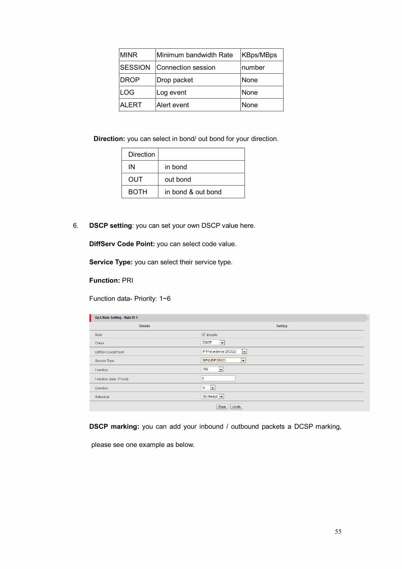
6. DSCP setting: you can set your own DSCP value here.
DiffServ Code Point: you can select code value.
Service Type: you can select their service type.
Function: PRI
Function data- Priority: 1~6
DSCP marking: you can add your inbound / outbound packets a DCSP marking,
please see one example as below.
56
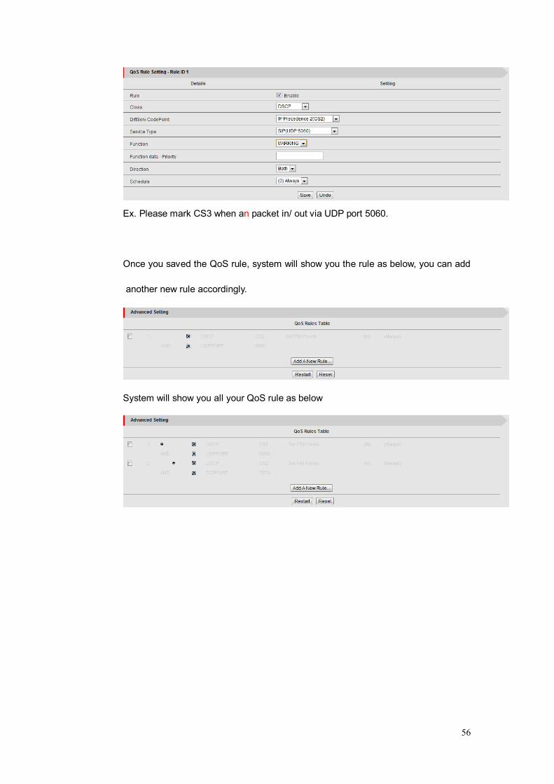
Ex. Please mark CS3 when an packet in/ out via UDP port 5060.
Once you saved the QoS rule, system will show you the rule as below, you can add
another new rule accordingly.
System will show you all your QoS rule as below

57
3.2.3. VLAN The VLAN function allows you to divide local network into different “virtual LAN”. In some
cases, ISP may need the router to support “VLAN tag” for certain kinds of services (e.g.
IPTV) to work properly.
There are 4 LAN ports with this router, so you can have up to 4 VLAN if required.
All 4 LAN ports belong to one VLAN by default. If you want to divide them into different
VLAN, you just need to assign different “VID” for them. If ISP requests a “VLAN Tag” with
your outgoing data, please remember to check the checkbox of “Tx TAG”.

58
3.2.4. Management
3.2.4.1. SNMP In brief, SNMP, the Simple Network Management Protocol, is a protocol designed to give a
user the capability to remotely manage a computer network by polling and setting terminal
values and monitoring network events.
1. Enable SNMP: You must check “Local”, “Remote” or both to enable SNMP function. If
“Local” is checked, this device will respond request from LAN. If “Remote” is checked,
this device will respond request from WAN.
2. Get Community: The community of Get Request is that this device will respond.
3. Set Community: The community of Set Request is that this device will accept.
4. IP 1, IP 2, IP 3, and IP 4: Enter the IP addresses of your SNMP Management PCs.
User have to configure where this device should send SNMP Trap message.
5. SNMP Version: Select proper SNMP Version that your SNMP Management software
supports.
6. WAN Access IP Address: If you want to limit the remote SNMP access to specific
computer, please enter the PC’s IP address. The default value is 0.0.0.0, and it means
that any Internet connected computer can get some information of the device with
SNMP protocol.
Afterwards, click on “Save” to store your settings or click “Undo” to give up the changes.
59
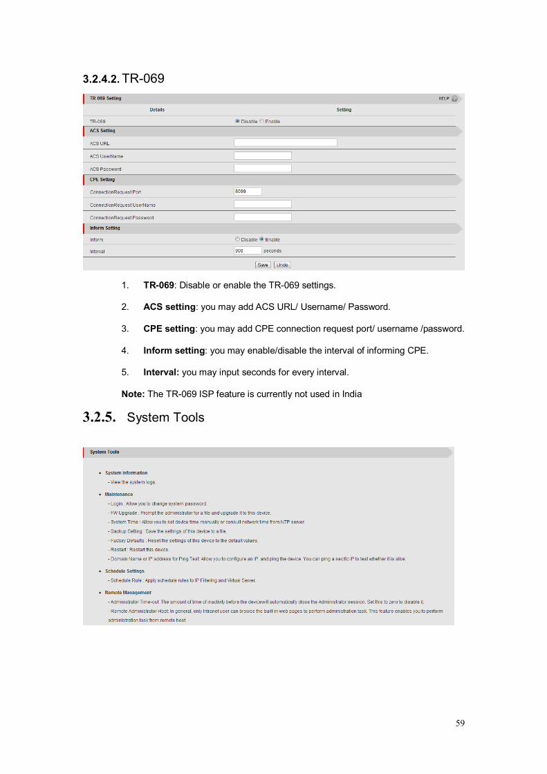
3.2.4.2. TR-069
1. TR-069: Disable or enable the TR-069 settings.
2. ACS setting: you may add ACS URL/ Username/ Password.
3. CPE setting: you may add CPE connection request port/ username /password.
4. Inform setting: you may enable/disable the interval of informing CPE.
5. Interval: you may input seconds for every interval.
Note: The TR-069 ISP feature is currently not used in India
3.2.5. System Tools

60
3.2.5.1. System Information
You can view the System Information WAN Type & Display time in this page.
3.2.5.2. System Log Local Log
You can check the entire local log.
3.2.5.3. System Log Remote Log
You can check all the Remote / System log.
3.2.5.4. System Log Email Log
You can check the entire Email log.

61
3.2.5.5. Maintenance
You can change the User name & password for Login to the Router.
3.2.5.6. Firmware Upgrade
You can upgrade firmware by clicking “Upgrade” button.
3.2.5.7. System Time
You can change the Time Zone. Default is GMT+5:30.
3.2.5.8. Diagnostic Tools & Misc.
You can Backup, Factory Defaults, Restart all the Settings.

62
3.2.5.9. Scheduling
You can also Schedule the entire Rule as per requirement.
3.2.5.10. Remote Management
You can control this Router from Public IP.
63
Note: It is recommended that you use an Ethernet connection to configure it
Chapter 4. Troubleshooting
This Chapter provides solutions to problems for the installation and operation of the WiFi
Broadband Router. You can refer to the following if you are having problems.
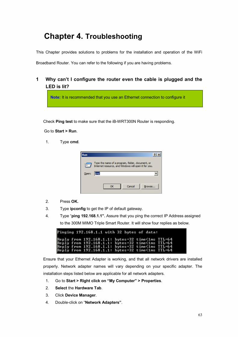
1 Why can’t I configure the router even the cable is plugged and the LED is lit?
Check Ping test to make sure that the iB-WRT300N Router is responding.
Go to Start > Run.
1. Type cmd.
2. Press OK.
3. Type ipconfig to get the IP of default gateway.
4. Type “ping 192.168.1.1”. Assure that you ping the correct IP Address assigned
to the 300M MIMO Triple Smart Router. It will show four replies as below.
Ensure that your Ethernet Adapter is working, and that all network drivers are installed
properly. Network adapter names will vary depending on your specific adapter. The
installation steps listed below are applicable for all network adapters.
1. Go to Start > Right click on “My Computer” > Properties.
2. Select the Hardware Tab.
3. Click Device Manager.
4. Double-click on “Network Adapters”.

64
5. Right-click on Wireless Card bus Adapter or your specific network adapter.
6. Select Properties to ensure that all drivers are installed properly.
7. Look under Device Status to see if the device is working properly.
8. Click “OK”.
2 What can I do if my Ethernet connection does not work properly? A. Make sure the RJ45 cable connects with the router.
B. Ensure that the setting on your Network Interface Card adapter is “Enabled”.
C. If settings are correct, ensure that you are not using a crossover Ethernet cable, not
all Network Interface Cards are MDI/MDIX compatible, and use a patch cable is
recommended.
D. If the connection still doesn’t work properly, then you can reset it to default.
3 Something wrong with the wireless connection?
A. Can’t setup a wireless connection?
I. Ensure that the SSID and the encryption settings are exactly the same to the
Clients.
II. Move the 300M MIMO Triple Smart Router and the wireless client into the
same room, and then test the wireless connection.
III. Disable all security settings such as WEP, and MAC Address Control.
IV. Turn off the 300 MIMO ADSL2+ Broadband Router and the client, then restart
it and then turn on the client again.
V. Ensure that the LEDs are indicating normally. If not, make sure that the power
and Ethernet cables are firmly connected.
VI. Ensure that the IP Address, subnet mask, gateway and DNS settings are
correctly entered for the network.
VII. If you are using other wireless device, home security systems or ceiling fans,
lights in your home, your wireless connection may degrade dramatically. Keep
your product away from electrical devices that generate RF noise such as
microwaves, monitors, electric motors…
65
B. What can I do if my wireless client can not access the Internet?
I. Out of range: Put the router closer to your client.
II. Wrong SSID or Encryption Key: Check the SSID or Encryption setting.
III. Connect with wrong AP: Ensure that the client is connected with the correct
Access Point.
i. Right-click on the Local Area Connection icon in the taskbar.
ii. Select View Available Wireless Networks in Wireless Configure. Ensure
you have selected the correct available network.
iii. Reset the 300M MIMO Triple Smart Router to default setting
C. Why does my wireless connection keep dropping?
I. Antenna Orientation.
i. Try different antenna orientations for the 300M MIMO Triple Smart Router.
ii. Try to keep the antenna at least 6 inches away from the wall or other
objects.
II. Try changing the channel on the Router and your Access Point and Wireless
adapter to a different channel to avoid interference.
III. Keep your product away from electrical devices that generate RF noise, like
microwaves, monitors, electric motors, etc.
4 What to do if I forgot my encryption key?
1. Go back to advanced setting to set up your Encryption key again.
2. Reset the Router to default setting
5 How to reset to default ?
1. Ensure the Router is powered on
2. Find the Reset button on the right side
3. After the Broadband Router reboots, it comes back to the factory default settings.

66
Appendix A. Spec Summary Table Device Interface iB-WRT300N
ADSL2 /2+ Standard Module
ADSL2+ connector, 1 x RJ-11 port ITU 992.1 (G.dmt) Annex A, ITU 992.2 (G.lite), ITU 992.3 ADSL2 (G.dmt.bis), ITU 992.5 ADSL2+
●
Ethernet WAN 1 xRJ45 port LAN/WAN configurable 1
Ethernet LAN 3 xRJ-45 ports, 10/100Mbps, auto-MDI/MDIX
3
Antenna 5 dBi x 2 Fixed antenna 2
USB port 2G/3G+ USB modem support 1 Reset / WPS / Wireless On/Off Button
3-In-1 Reset / WPS / Wireless On/Off Button
1
LED Indication ADSL/ LAN1 ~ LAN4/ WiFi ●
Power Jack DC Power Jack, powered via external DC 5V/ 2A switching power adapter
1
Wireless LAN (WiFi) Standard IEEE 802.11b/g/n (2x2) compliance ● SSID SSID broadcast ● Channel Auto-selection, manually ●
Security WEP, WPA, WPA-PSK, WPA2, WPA2-PSK
●
WPS WPS (Wi-Fi Protected Setup) ● WMM WMM (Wi-Fi Multimedia) ● Functionality
ADSL WAN PPPoE / PPPoA / IPoA / Static IP / Dynamic IP/Bridge up to 8 PVCs supported
●
WAN Connection Auto-reconnect, dial-on-demand, manually
●
Ethernet WAN
ADSL as primary, LAN Port 1 configures to WAN for WAN connection when ADSL line is not working
●

67
IPv6 support Support IPv4/IPv6 dual stack protocol ●
One-to-Many NAT Virtual server, special application, DMZ, IPTV IGMP V1 V2 Pass through
●
NAT Session Support NAT session ●
SPI Firewall IP/Service filter, URL blocking, MAC control
●
DoS Protection DoS (Deny of Service) detection and protection
●
Routing Protocol Static route, dynamic route (RIP v1/v2) ●
IPTV features Support IPTV IGMPv1/v2/v3 snooping and filtering, VLAN tagged/ Untagged frames
●
QoS
Support QoS mechanism for prioritizing the various type of traffics, TOS/DSCP to 802.1p mapping (DiffServ)
●
Management SNMP, UPnP IGD, Syslog ● Remote Management
Yes ●
Administration Web-based UI, remote login, backup/restore setting
●
Environment & Certification Package Content iB-WRT300N, Power adapter, Quick
Installation Guide, CD ●
Device dimension (mm) 150x112x20 ●
Operation Temp. Temp.: 0~40°C, Humidity 10%~90% non-condensing
●
EMI Certification CE/FCC compliance ●
RoHS RoHS compliance ●
*Specifications are subject to change without prior notice.
68
Appendix B: Glossary 802.11b - The 802.11b standard specifies a wireless product networking at 11 Mbps
using direct-sequence spread-spectrum (DSSS) technology and operating in the
unlicensed radio spectrum at 2.4GHz, and WEP encryption for security. 802.11b
networks are also referred to as Wi-Fi networks.
802.11g - specification for wireless networking at 54 Mbps using direct-sequence
spread-spectrum (DSSS) technology, using OFDM modulation and operating in the
unlicensed radio spectrum at 2.4GHz, and backward compatibility with IEEE 802.11b
devices, and WEP encryption for security.
Ad-hoc Network - An ad-hoc network is a group of computers, each with a Wireless N USB Adapter, connected as an independent 802.11 wireless LAN. Ad-hoc wireless computers operate on a peer-to-peer basis, communicating directly with each other without the use of an access point. Ad-hoc mode is also referred to as an Independent Basic Service Set (IBSS) or as peer-to-peer mode, and is useful at a departmental scale or SOHO operation.
DSSS (Direct-Sequence Spread Spectrum) - DSSS generates a redundant bit
pattern for all data transmitted. This bit pattern is called a chip (or chipping code).
Even if one or more bits in the chip are damaged during transmission, statistical
techniques embedded in the receiver can recover the original data without the need
of retransmission. To an unintended receiver, DSSS appears as low power wideband
noise and is rejected (ignored) by most narrowband receivers. However, to an
intended receiver (i.e. another wireless LAN endpoint), the DSSS signal is recognized
as the only valid signal, and interference is inherently rejected (ignored).
FHSS (Frequency Hopping Spread Spectrum) - FHSS continuously changes (hops)
the carrier frequency of a conventional carrier several times per second according to
a pseudo-random set of channels. Because a fixed frequency is not used, and only
the transmitter and receiver know the hop patterns, interception of FHSS is extremely
difficult.

69
Infrastructure Network - An infrastructure network is a group of computers or other
devices, each with a Wireless N USB Adapter, connected as an 802.11 wireless LAN.
In infrastructure mode, the wireless devices communicate with each other and to a
wired network by first going through an access point. An infrastructure wireless
network connected to a wired network is referred to as a Basic Service Set (BSS). A
set of two or more BSS in a single network is referred to as an Extended Service Set
(ESS). Infrastructure mode is useful at a corporation scale, or when it is necessary to
connect the wired and wireless networks.
Spread Spectrum - Spread Spectrum technology is a wideband radio frequency
technique developed by the military for use in reliable, secure, mission-critical
communications systems. It is designed to trade off bandwidth efficiency for reliability,
integrity, and security. In other words, more bandwidth is consumed than in the case
of narrowband transmission, but the trade off produces a signal that is, in effect,
louder and thus easier to detect, provided that the receiver knows the parameters of
the spread-spectrum signal being broadcast. If a receiver is not tuned to the right
frequency, a spread-spectrum signal looks like background noise. There are two
main alternatives, Direct Sequence Spread Spectrum (DSSS) and Frequency
Hopping Spread Spectrum (FHSS).
SSID - A Service Set Identification is a thirty-two character (maximum) alphanumeric
key identifying a wireless local area network. For the wireless devices in a network to
communicate with each other, all devices must be configured with the same SSID.
This is typically the configuration parameter for a wireless PC card. It corresponds to
the ESSID in the wireless Access Point and to the wireless network name. See also
Wireless Network Name and ESSID.
WEP (Wired Equivalent Privacy) - A data privacy mechanism based on a 64-bit or
128-bit or 152-bit shared key algorithm, as described in the IEEE 802.11 standard.
Wi-Fi - A trade name for the 802.11b wireless networking standard, given by the
Wireless Ethernet Compatibility Alliance (WECA, see http://www.wi-fi.net), an
industry standards group promoting interoperability among 802.11b devices.
WLAN (Wireless Local Area Network) - A group of computers and associated
devices communicate with each other wirelessly, which network serving users are
limited in a local area.
WPA (Wi-Fi Protected Access) - A wireless security protocol use TKIP (Temporal
Key Integrity Protocol) encryption, which can be used in conjunction with a RADIUS
server.

70
Appendix C: Contact Information
COPYRIGHT & TRADEMARKS Specifications are subject to change without notice. iBall Baton is a registered trademark of Best IT World (India) Pvt. Ltd. Other brands and product names are trademarks or registered trademarks of their respective holders.
No part of the specifications may be reproduced in any form or by any means or used to make any derivative such as translation, transformation, or adaptation without permission from Best IT World (India) Pvt. Ltd. All rights reserved.
Note: For any technical help on iBall Baton products please contact [email protected]
www.iBallBaton.com