Embed Size (px)
Citation preview
DESIGN OFSTEEL STRUCTURES
D i f C i M bDesign of Compression Member
A structural member carrying axial or eccentric l ll bcompressive load is called compression member.
Types of compression member :
The vertical compression member in RCC building isp gtermed as column, where as for steel structure it is called stanchion.
The compression member in roof truss or bracing is calledas strutas strut.
The principle compression member in a crane is calledp p pboom.
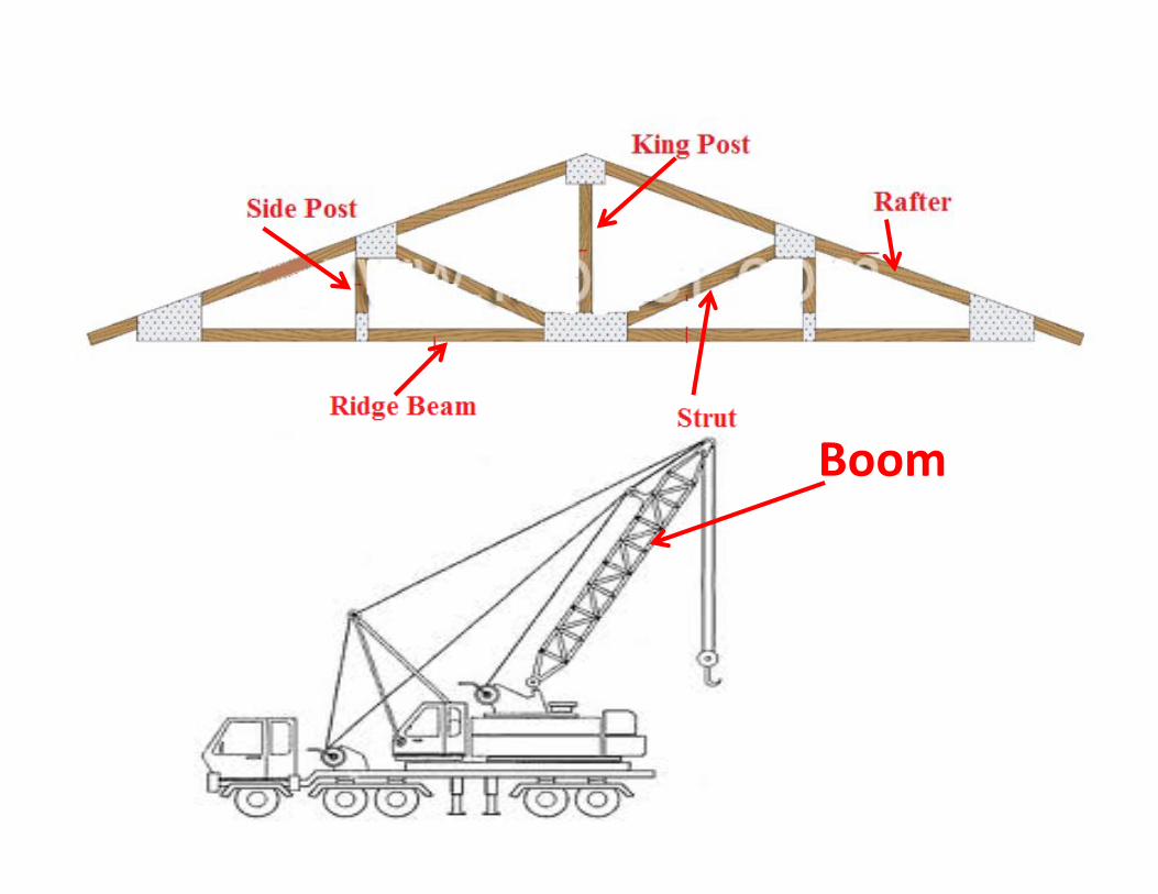
Boom
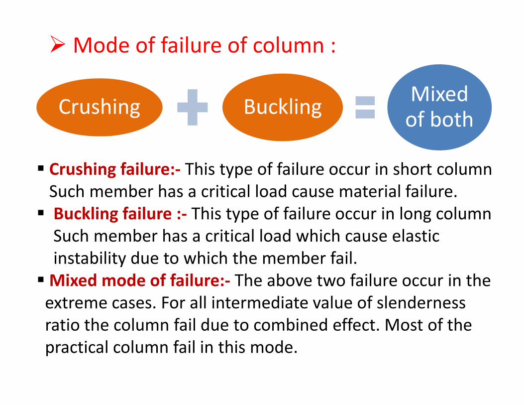
Mode of failure of column :
Crushing Buckling Mixed of bothof both
Crushing failure:‐ This type of failure occur in short columng ypSuch member has a critical load cause material failure.Buckling failure :‐ This type of failure occur in long columnSuch member has a critical load which cause elasticinstability due to which the member fail.Mixed mode of failure: The above two failure occur in theMixed mode of failure:‐ The above two failure occur in the extreme cases. For all intermediate value of slendernessratio the column fail due to combined effect. Most of theratio the column fail due to combined effect. Most of thepractical column fail in this mode.
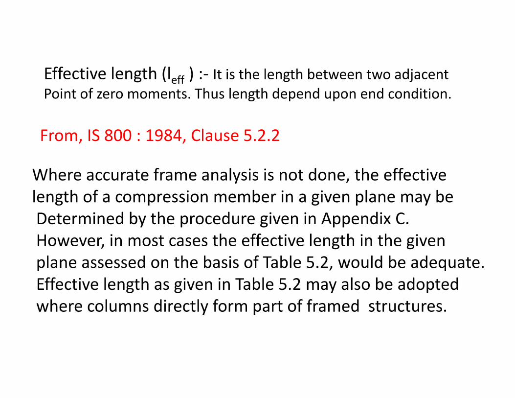
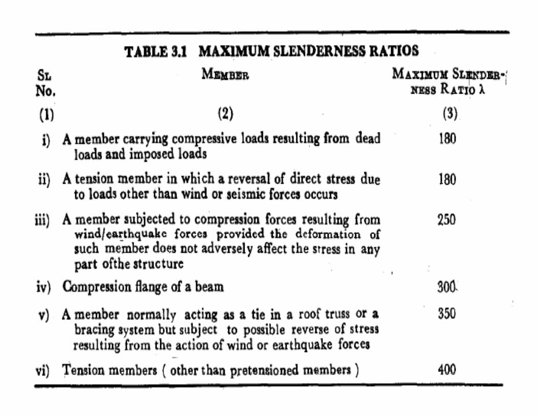
Effective length (l ) : It is the length between two adjacentEffective length (leff ) :‐ It is the length between two adjacent Point of zero moments. Thus length depend upon end condition.
Where accurate frame analysis is not done the effective
From, IS 800 : 1984, Clause 5.2.2
Where accurate frame analysis is not done, the effective length of a compression member in a given plane may beDetermined by the procedure given in Appendix C.ete ed by t e p ocedu e g e ppe d C.However, in most cases the effective length in the givenplane assessed on the basis of Table 5.2, would be adequate.Effective length as given in Table 5.2 may also be adoptedwhere columns directly form part of framed structures.
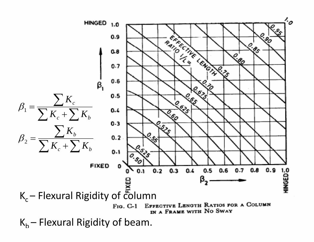
∑ cKβ
∑∑∑
∑+
=
b
bc
K
KK1
β
β
∑∑∑+
=bc KK2β
K – Flexural Rigidity of columnKc Flexural Rigidity of column
Kb – Flexural Rigidity of beam.
Buckling failure : Euler’s Theory
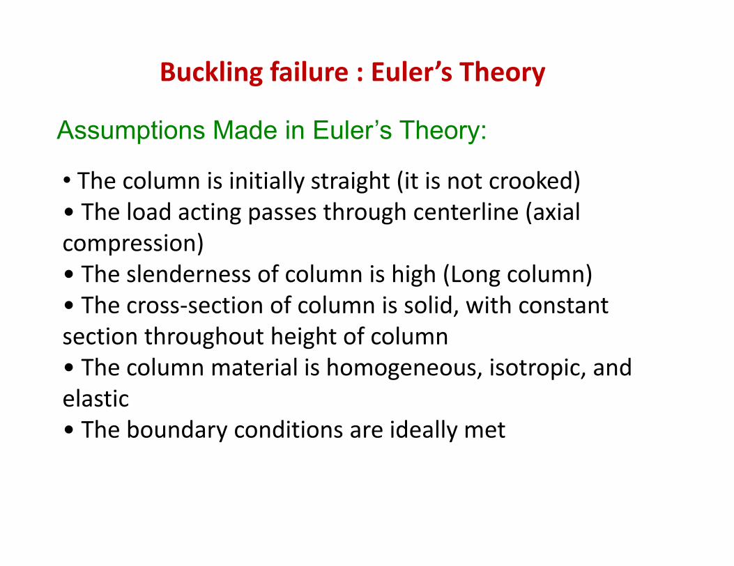
Assumptions Made in Euler’s Theory:
Th l i i iti ll t i ht (it i t k d)• The column is initially straight (it is not crooked)• The load acting passes through centerline (axial compression)compression)• The slenderness of column is high (Long column)• The cross‐section of column is solid, with constant section throughout height of column• The column material is homogeneous, isotropic, and l ielastic• The boundary conditions are ideally met
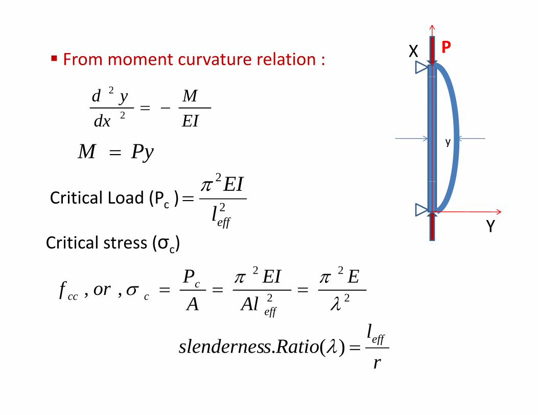
PXFrom moment curvature relation :
EIM
dxyd
−=2
2
2EIπ
yPyM =
Y
Critical Load (Pc ) 2efflEIπ
=
22 ππ EEIPf c
Critical stress (σc)
22,,λ
σAlA
orfeff
cccc ===
leff
rRatiosslendernes eff=)(. λ
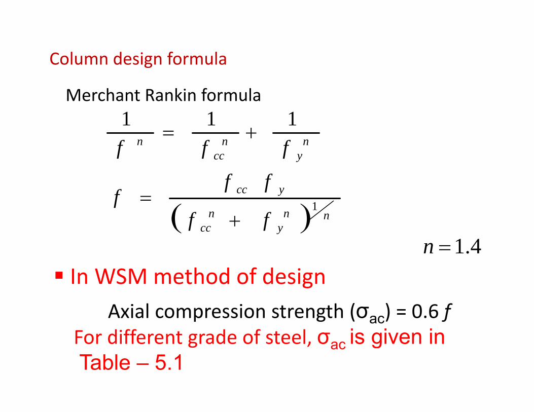
Column design formula
Merchant Rankin formula111
+ ny
ncc
n
ff
fff+=
( ) nny
ncc
ycc
ff
fff 1
+=( )y
In WSM method of design4.1=n
S et od o des gAxial compression strength (σac) = 0.6 f
For different grade of steel σ is given inFor different grade of steel, σac is given inTable – 5.1
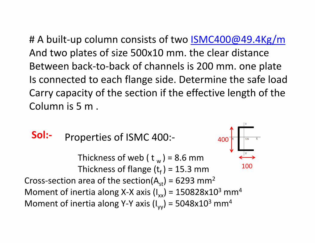
# A built‐up column consists of two [email protected]/mAnd two plates of size 500x10 mm. the clear distance Between back‐to‐back of channels is 200 mm. one plate
d h fl d h f l dIs connected to each flange side. Determine the safe load Carry capacity of the section if the effective length of theColumn is 5 mColumn is 5 m .
Sol:‐ Properties of ISMC 400: 400
100
Sol:
Thickness of web ( t w ) = 8.6 mmThickness of flange (t ) 15 3 mm
Properties of ISMC 400:‐
100Thickness of flange (tf ) = 15.3 mmCross‐section area of the section(Ast) = 6293 mm2
Moment of inertia along X‐X axis (Ixx) = 150828x103 mm4
Moment of inertia along Y‐Y axis (Iyy) = 5048x103 mm4
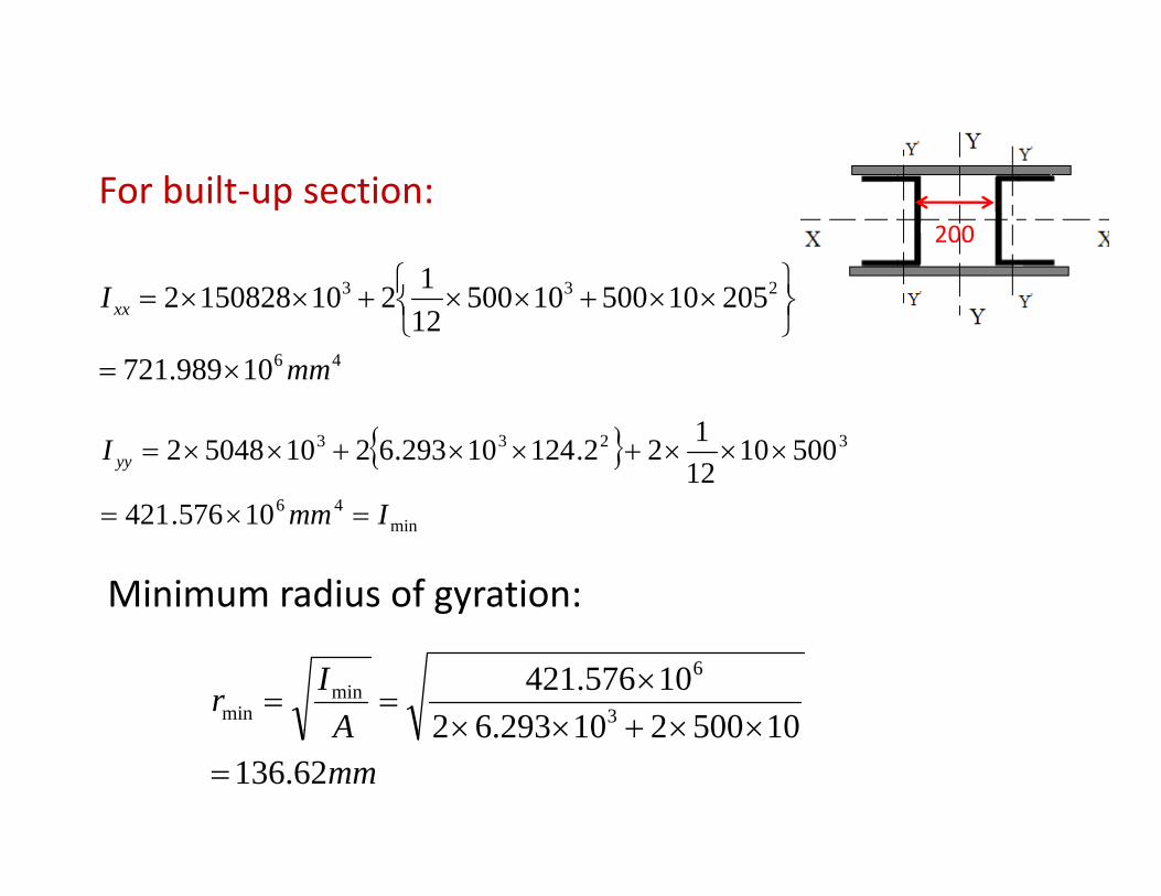
For built‐up section:
1 ⎫⎧
200
46
233
10989.721
20510500105001212101508282
mm
Ixx
×=⎭⎬⎫
⎩⎨⎧ ××+××+××=
{ }46
3233
10576421
5001012122.12410293.621050482
I
I yy ×××+××+××=
min4610576.421 Imm =×=
Minimum radius of gyration:
AIr
105002102936210576.421
3
6min
min ××+×××
==
mmA
62.13610500210293.62
=××+××
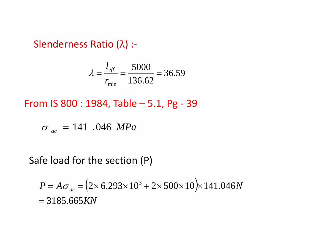
Slenderness Ratio ( ) :‐Slenderness Ratio ( ) :‐
59.365000===
leffλ 59.3662.136minr
λ
From IS 800 : 1984, Table – 5.1, Pg ‐ 39
MPaac 046.141=σ
From IS 800 : 1984, Table 5.1, Pg 39
Safe load for the section (P)
( )KN
NAP ac
6653185046.14110500210293.62 3 ×××+××== σ
KN665.3185=
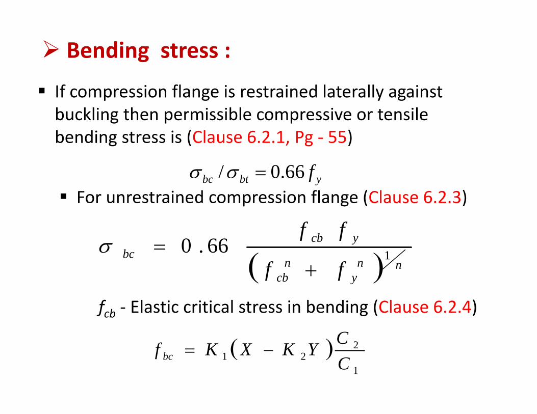
Bending stress :
If compression flange is restrained laterally against buckling then permissible compressive or tensilebending stress is (Clause 6.2.1, Pg ‐ 55)
ybtbc f66.0/ =σσ ybtbc fFor unrestrained compression flange (Clause 6.2.3)
ff
( ) nny
ncb
ycbbc
ff
ff166.0
+=σ
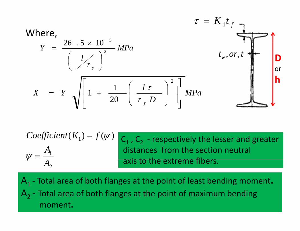
fcb ‐ Elastic critical stress in bending (Clause 6.2.4)
C( )1
221 C
CYKXKf bc −=
510526 ×
ftK 1=τWhere,
MPa
rl
Y
y
2105.26
⎟⎠⎞
⎜⎝⎛
×=
Dor
tortw ,,
MPaDr
lYX⎥⎥
⎦
⎤
⎢⎢
⎣
⎡
⎟⎟⎠
⎞⎜⎜⎝
⎛+=
2
2011 τ
h
Dr y ⎥⎦
⎢⎣ ⎠⎝20
1
1 )()(A
fKtCoefficien
=
=
ψ
ψ C1 , C2 ‐ respectively the lesser and greaterdistances from the section neutrali t th t fib
2Aψ
A1 ‐ Total area of both flanges at the point of least bending moment.
axis to the extreme fibers.
A2 ‐ Total area of both flanges at the point of maximum bending moment.
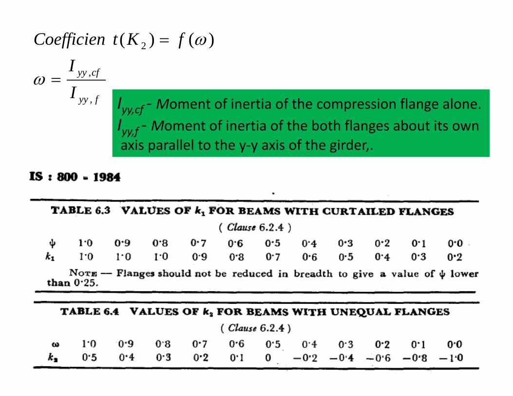
cfyyIfKtCoefficien 2 )()( = ω
fyy
cfyy
I ,
,=ωIyy,cf ‐ Moment of inertia of the compression flange alone.I Moment of inertia of the both flanges abo t its o nIyy,f ‐ Moment of inertia of the both flanges about its ownaxis parallel to the y‐y axis of the girder,.
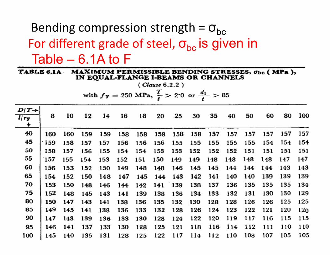
Bending compression strength = σbcFor different grade of steel, σbc is given inFor different grade of steel, σbc is given inTable – 6.1A to F
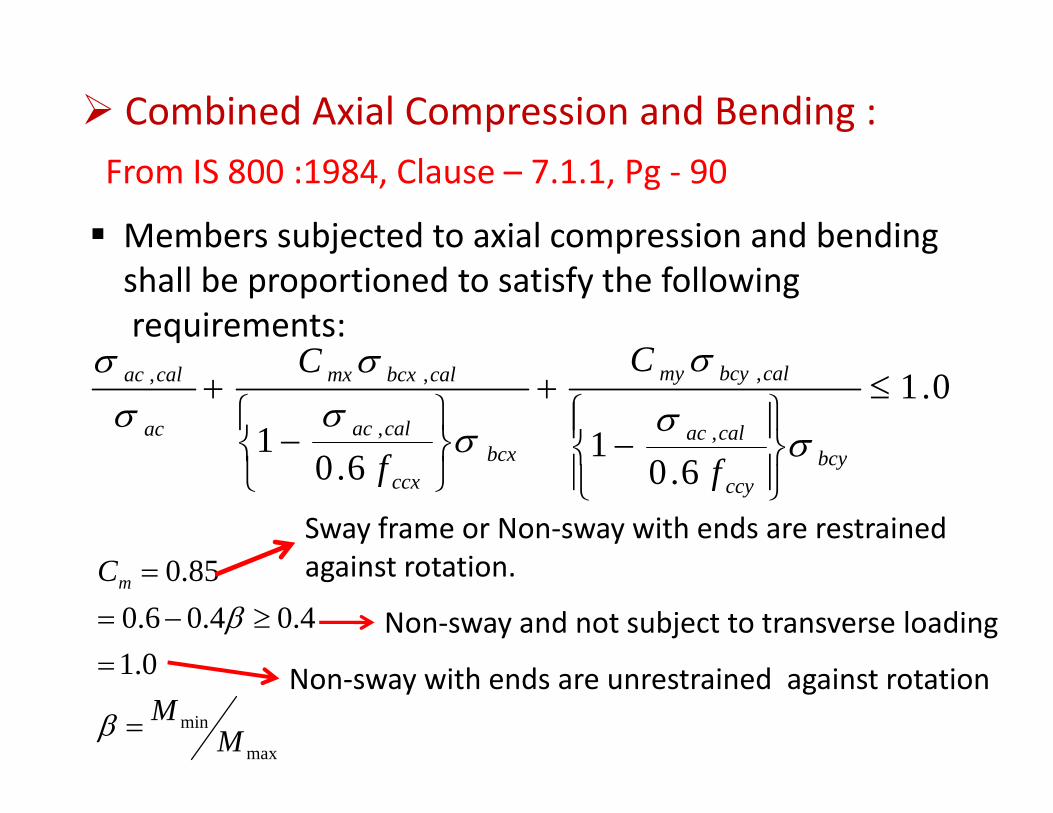
Combined Axial Compression and Bending :From IS 800 :1984, Clause – 7.1.1, Pg ‐ 90
Members subjected to axial compression and bendingj p gshall be proportioned to satisfy the following requirements:
CC σ0.1
1601 ,
,
,
,, ≤
⎪⎪⎬⎫
⎪⎪⎨⎧
−
+
⎭⎬⎫
⎩⎨⎧
−+
bcycalac
calbcymy
bcxcalac
calbcxmx
ac
calac C
f
C
σσ
σ
σσσ
σσ
6.06.0 ⎪⎭⎬
⎪⎩⎨
⎭⎬
⎩⎨ bcy
ccybcx
ccx ff
850CSway frame or Non‐sway with ends are restrained
i t t ti
014.04.06.0
85.0Cm
=≥−=
=β
against rotation.
Non‐sway and not subject to transverse loading
max
min
0.1
MM=
=
βNon‐sway with ends are unrestrained against rotation
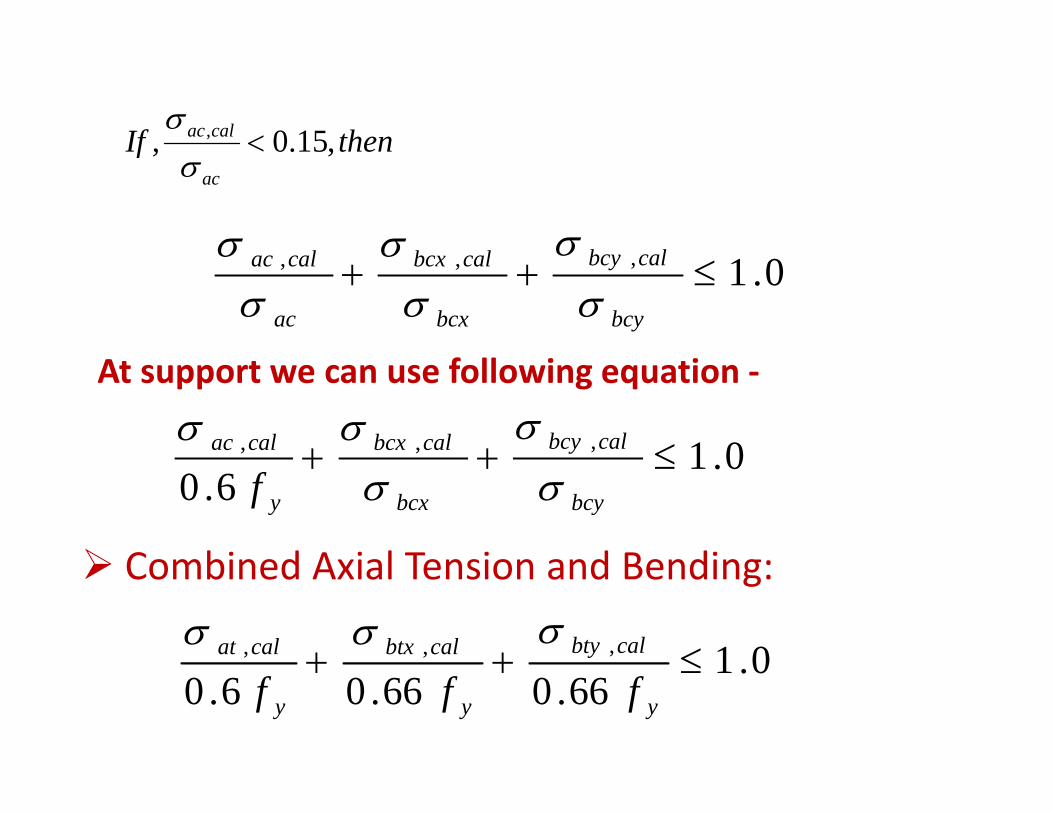
thenIf calac ,15.0, , <σ
lblbl σσσ
thenIfac
,15.0, <σ
0.1,,, ≤++bcy
calbcy
bcx
calbcx
ac
calac
σσ
σσ
σσ
01,,, ≤++ calbcycalbcxcalac σσσAt support we can use following equation ‐
0.16.0
≤++bcybcxyf σσ
Combined Axial Tension and Bending:Combined Axial Tension and Bending:
01,,, ≤++ calbtycalbtxcalat σσσ0.1
66.066.06.0≤++
yyy fff
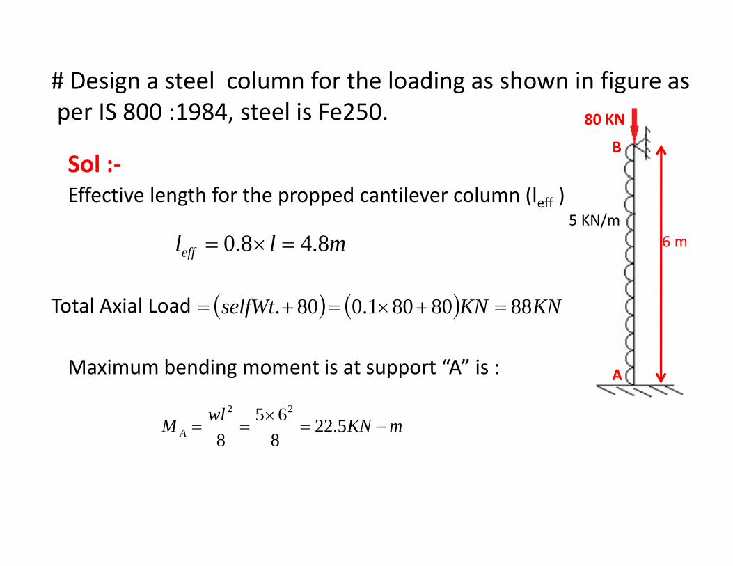
# Design a steel column for the loading as shown in figure asIS 800 1984 t l i F 250per IS 800 :1984, steel is Fe250. 80 KN
BSol :‐
5 KN/m6 m
Effective length for the propped cantilever column (leff )
mll ff 8480 =×= mlleff 8.48.0 =×=
( ) ( ) KNKNselfWt 8880801.080. =+×=+=Total Axial Load
A
( ) ( )
Maximum bending moment is at support “A” is :
mKNwlM A −=×
== 5.22865
8
22
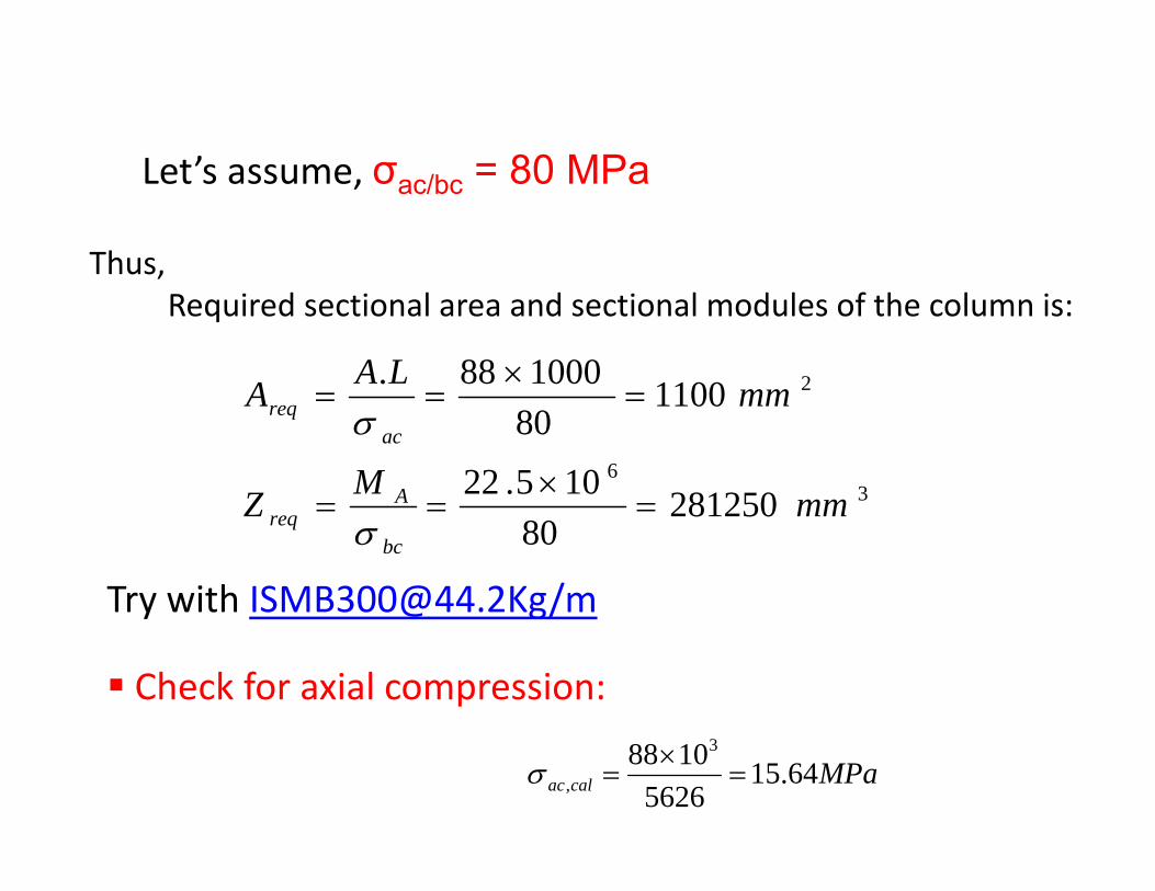
Let’s assume σ = 80 MPaLet’s assume, σac/bc = 80 MPa
Thus,,Required sectional area and sectional modules of the column is:
21100100088.LAA ×
36
2
281250105.22
110080
mmMZ
mmA
A
acreq
×
===σ
28125080
mmZbc
Areq ===
σ
Try with [email protected]/my @ g/
Check for axial compression:
MPacalac 64.155626
1088 3
, =×
=σ
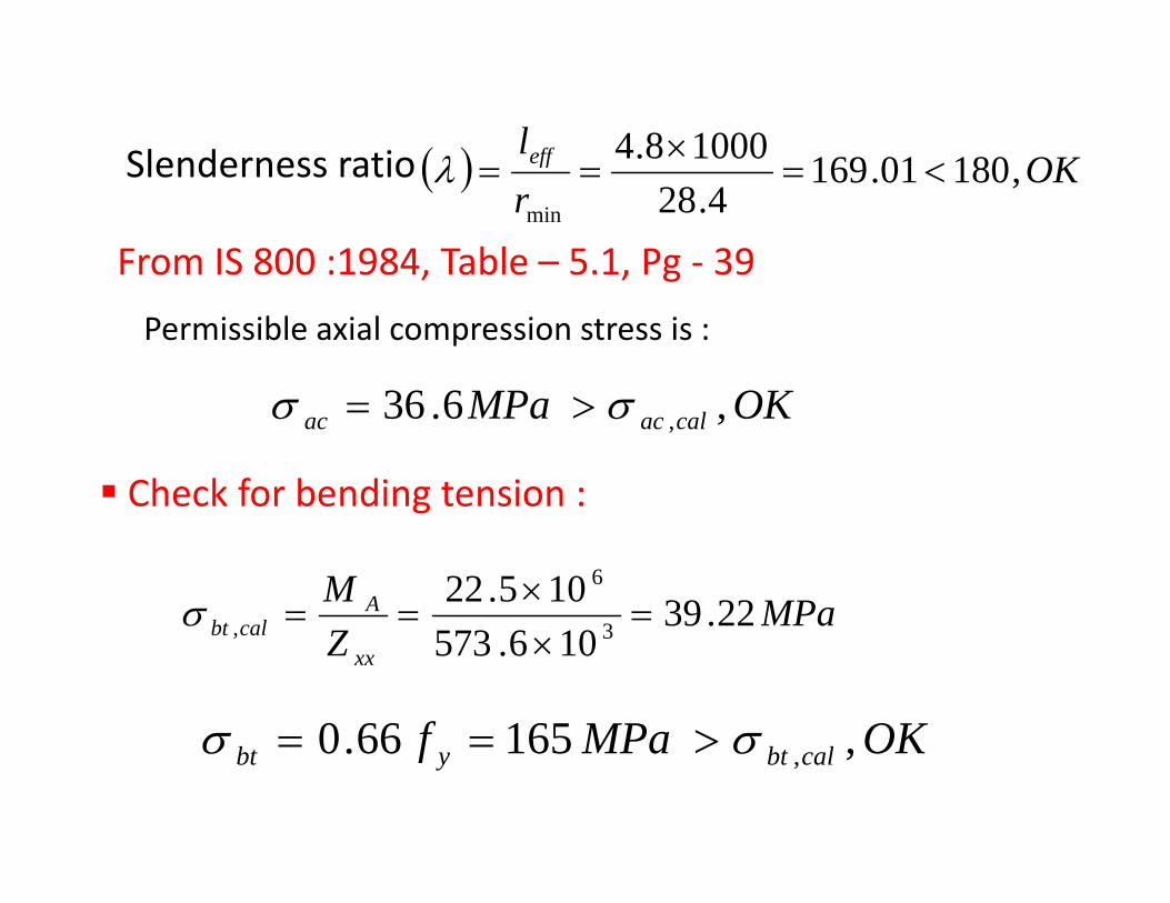
Slenderness ratio ( ) OKleff 1800116910008.4
<×λSlenderness ratio ( ) OK
rff ,18001.169
4.28min
<===λ
From IS 800 :1984, Table – 5.1, Pg ‐ 39g
OKMP636
Permissible axial compression stress is :
OKMPa calacac ,6.36 ,σσ >=
Check for bending tension :g
MPaM Albt 22.39105.22 6
=×
==σ MPaZ xx
calbt 22.39106.573 3, ×
σ
OKMPaf 165660 σσ >== OKMPaf calbtybt ,16566.0 ,σσ >==
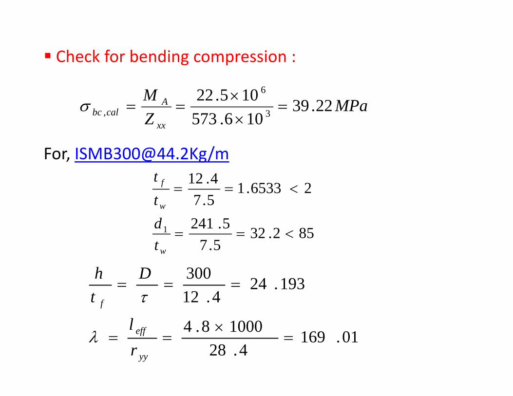
Check for bending compression :
MPaZM A
calbc 22.39106.573
105.223
6
, =××
==σZ xx 106.573 ×
412tFor, [email protected]/m
5241
26533.15.74.12
<==w
f
dtt
852.325.7
5.2411 <==wt
d
300Dh
100084
193.244.12
300===
f
l
Dth
τ
01.1694.28
10008.4=
×==
yy
eff
rl
λ

From IS 800 1984, Table‐ 6.1B, Pg ‐ 58
D/Γ 20 25 24.193Leff/ ry
160 101 93 94.2912
170 98 89 90.4526
OKMP832690 > OKMPa calbcbc ,8326.90 ,σσ >=
Combined Axial Compression and Bending check:
MPaMPa accalac 6.36,64.15, == σσMPaMPa bccalbc 83.90,22.39, == σσ
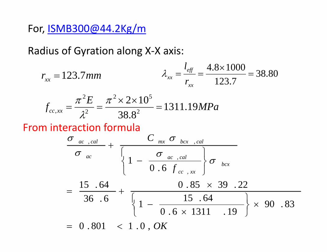
For, [email protected]/m
d f l
mmr 7.123=
Radius of Gyration along X‐X axis:
80.387123
10008.4=
×== eff
xx
lλmmrxx 7.123 7.123xx
xx r
MPaEf xxcc 19.13111022
52
2
2
=××
==ππf xxcc 8.38 22, λ
C calbcxmxcalac σσFrom interaction formula
f bcxxxcc
calac
calbcxmx
ac
calac
6.01
,
,
,,
⎭⎬⎫
⎩⎨⎧
−
+
σσσ
839064.151
22.3985.06.36
64.15,
×⎬⎫
⎨⎧ −
×+=
⎭⎩
OK,0.1801.0
83.9019.13116.0
1
<=
×⎭⎬
⎩⎨ ×
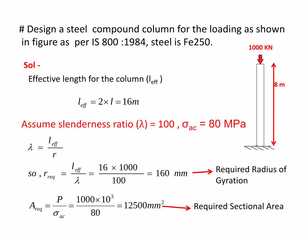
# Design a steel compound column for the loading as shownin figure as per IS 800 :1984 steel is Fe250in figure as per IS 800 :1984, steel is Fe250.
1000 KN
Sol ‐
8 mEffective length for the column (leff )
mll ff 162 =×= mlleff 162 =×=
Assume slenderness ratio ( ) = 100 , σac = 80 MPa
rl eff=λ
mml
rso effreq 160
100100016, =
×==
λRequired Radius of Gyration
23
1250080
101000 mmPAac
req =×
==σ
Required Sectional Area
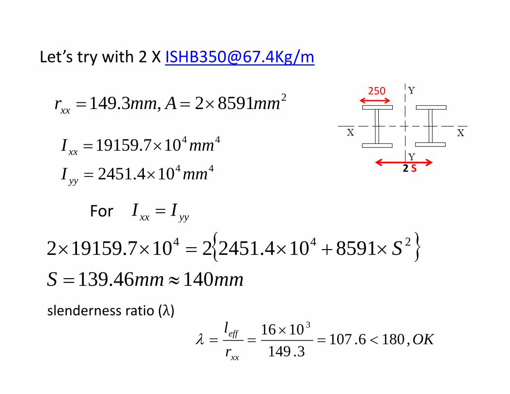
Let’s try with 2 X [email protected]/m
285912,3.149 mmAmmrxx ×==250
2 S44
44
1042451
107.19159
mmI
mmIxx
×
×=
104.2451 mmI yy ×=
yyxx II =For yy
{ }S8591104.24512107.191592 244 ×+×=××mmmmS 14046.139 ≈=
slenderness ratio (λ)
OKrl
xx
eff ,1806.1073.149
1016 3
<=×
==λ
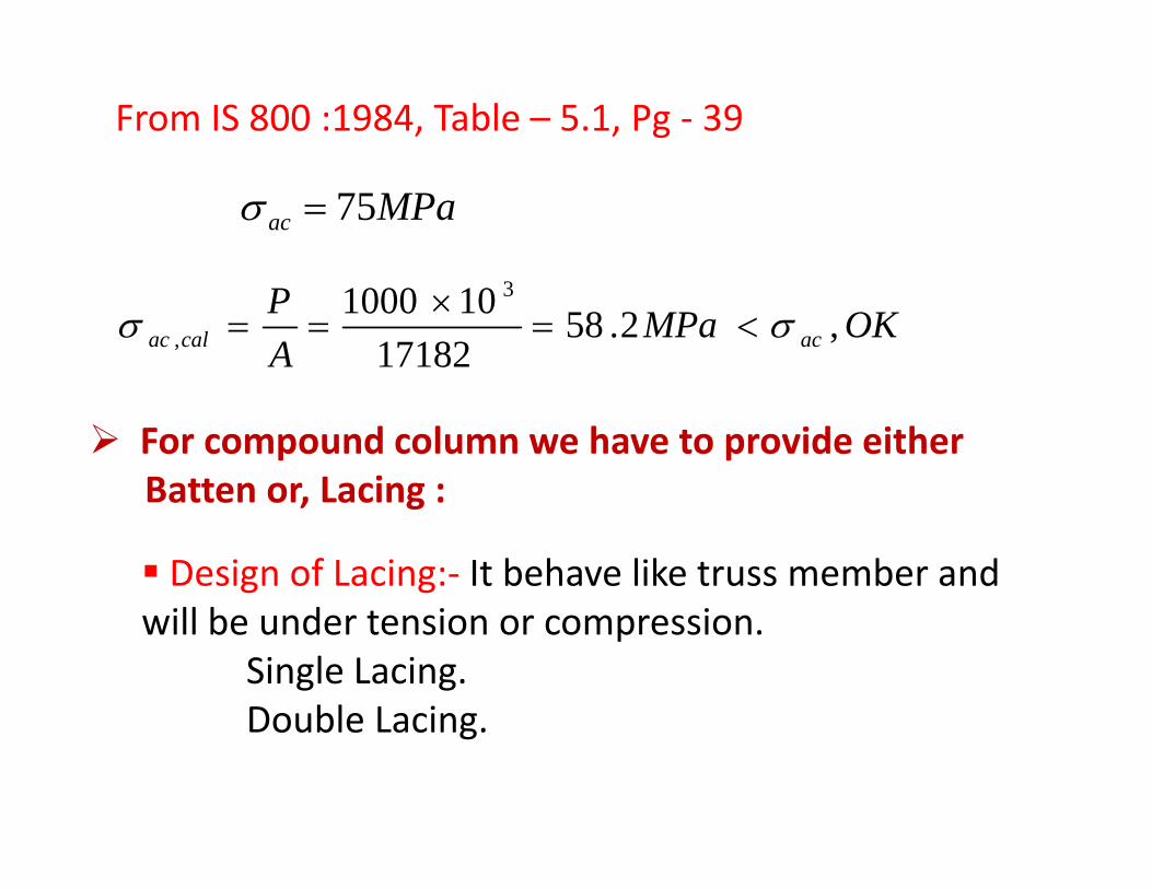
From IS 800 :1984, Table – 5.1, Pg ‐ 39
MPaac 75=σ
OKMPaAP
accalac ,2.5817182
101000 3
, σσ <=×
==
For compound column we have to provide eitherBatten or, Lacing :Batten or, Lacing :
Design of Lacing:‐ It behave like truss member andill b d t i iwill be under tension or compression.
Single Lacing.Double LacingDouble Lacing.
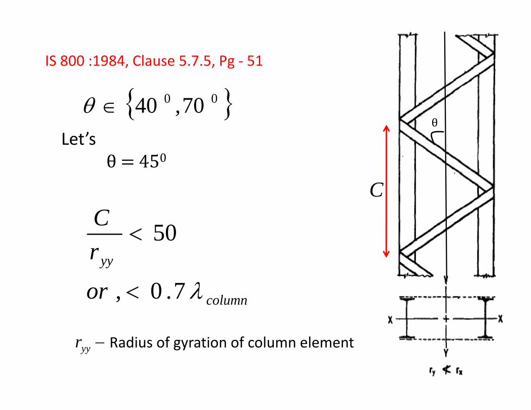
IS 800 :1984, Clause 5.7.5, Pg ‐ 51
θ{ }00 70,40∈θ
Let’s 0
CC 50<yyr
λ0
50<
columnor λ7.0, <
−yyr Radius of gyration of column element
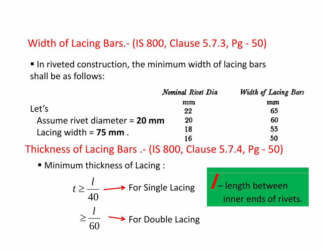
Width of Lacing Bars.‐ (IS 800, Clause 5.7.3, Pg ‐ 50)Width of Lacing Bars. (IS 800, Clause 5.7.3, Pg 50)
In riveted construction, the minimum width of lacing bars shall be as follows:shall be as follows:
Let’sLet s Assume rivet diameter = 20 mmLacing width = 75 mm .
Thickness of Lacing Bars .‐ (IS 800, Clause 5.7.4, Pg ‐ 50)Minimum thickness of Lacing :
40lt ≥ For Single Lacing l – length between
inner ends of rivets.
60l
≥ For Double Lacing
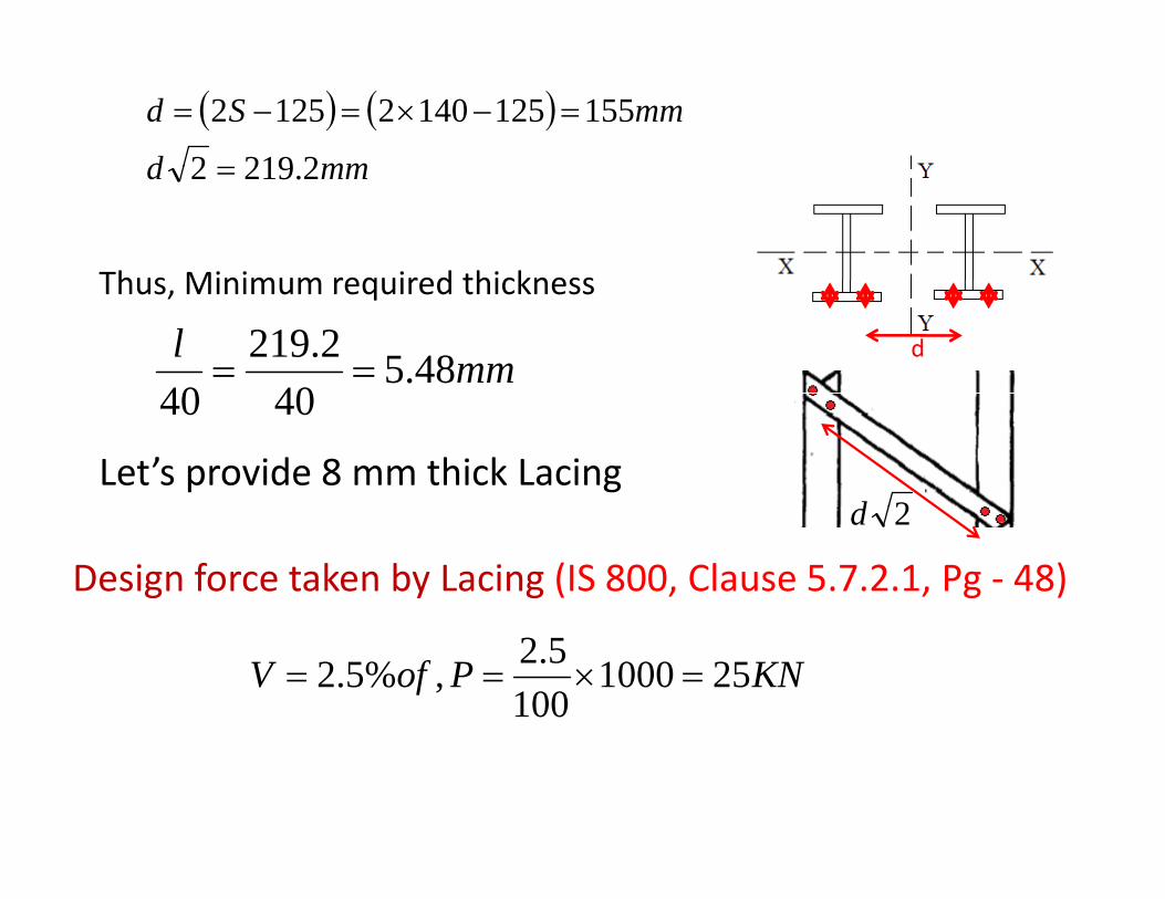
( ) ( )mmd
mmSd
22192
15512514021252 =−×=−=
mmd 2.2192 =
Thus Minimum required thickness
dmml 48.540
2.21940
==
Thus, Minimum required thickness
2d
4040
Let’s provide 8 mm thick Lacing2d
Design force taken by Lacing (IS 800, Clause 5.7.2.1, Pg ‐ 48)
KNPofV 251000100
5.2,%5.2 =×==
F
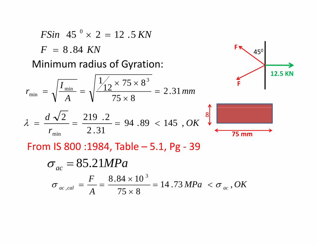
KNFSin 5.12245 0 =×
12.5 KN
450FKNF 84.8=
Minimum radius of Gyration:
Fmm
AIr 31.2
875
875121 3
minmin =
×
××==
75 mm
8OK
rd ,14589.94
31.22.2192
min
<===λ
From IS 800 :1984, Table – 5.1, Pg ‐ 39
MPaac 21.85=σ ac
OKMPaAF
accalac ,73.148751084.8 3
, σσ <=××
==
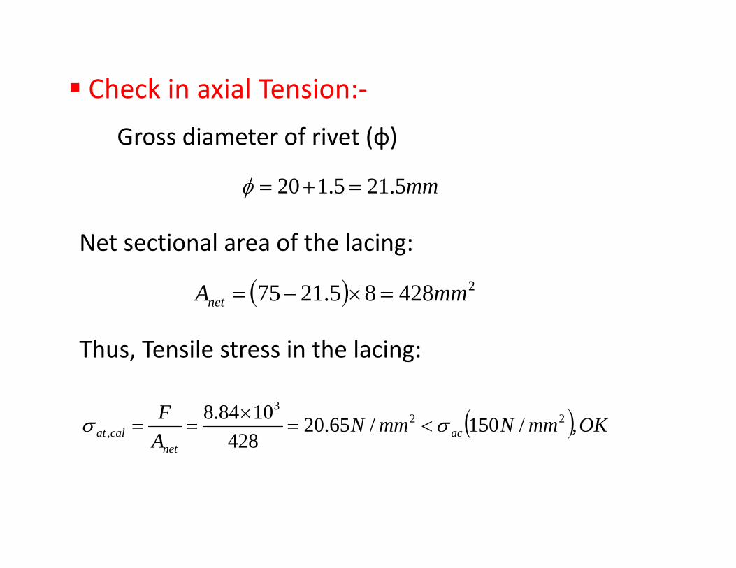
Check in axial Tension:‐
Gross diameter of rivet (ф)
mm5.215.120 =+=φ
Net sectional area of the lacing:
( ) 242885.2175 mmAnet =×−=
Net sectional area of the lacing:
Thus, Tensile stress in the lacing:
( ) OKmmNmmNAF
acnet
calat ,/150/65.20428
1084.8 223
, σσ <=×
==
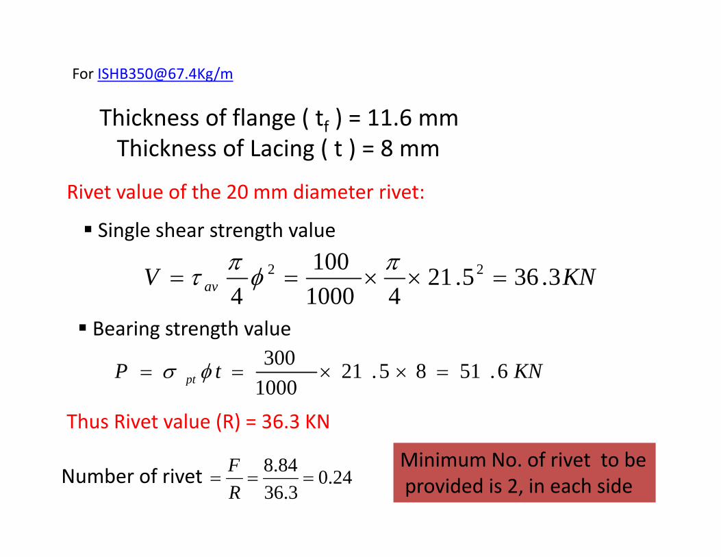
For [email protected]/m
Thickness of flange ( tf ) = 11.6 mmThickness of Lacing ( t ) = 8 mm
Rivet value of the 20 mm diameter rivet:
Single shear strength value
KNV av 3.365.2141000
1004
22 =××==πφπτ
Bearing strength value
KNtP pt 6.5185.211000300
=××== φσ p 1000Thus Rivet value (R) = 36.3 KN
Mi i N f i t t bNumber of rivet 24.0
3.3684.8
===RF Minimum No. of rivet to be
provided is 2, in each side
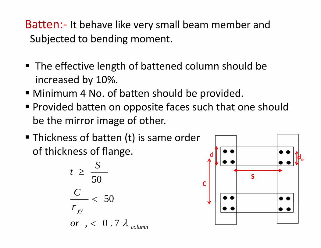
Batten:‐ It behave like very small beam member and Subjected to bending moment.
The effective length of battened column should bei d b 10%increased by 10%.Minimum 4 No. of batten should be provided.Provided batten on opposite faces such that one shouldProvided batten on opposite faces such that one shouldbe the mirror image of other.
Thickness of batten (t) is same order
ded
Thickness of batten (t) is same orderof thickness of flange.
St ≥C
S
C
t
50
50
<
≥
column
yy
or
r
λ7.0, <
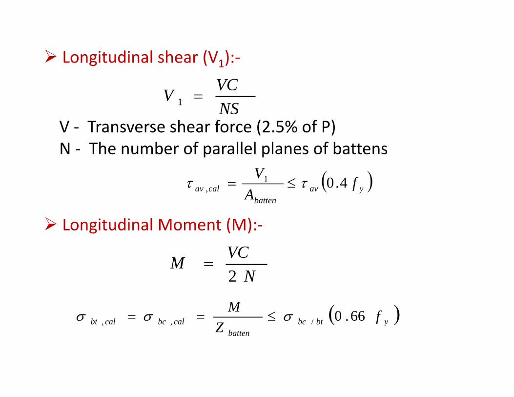
Longitudinal shear (V1):‐
NSVCV =1
V T h f (2 5% f P)V ‐ Transverse shear force (2.5% of P) N ‐ The number of parallel planes of battens
( )V
Longitudinal Moment (M):
( )yavbatten
calav fA
V 4.01, ττ ≤=
Longitudinal Moment (M):‐
NVCM2
=N2
( )ybtbccalbccalbt fZ
M 66.0/,, σσσ ≤== ( )ybtbcbatten
calbccalbt fZ /,,
Design of Flexural Member
A beam is a structural member subjected tojtransverse load, i.e load perpendicular to thelongitudinal axis. g
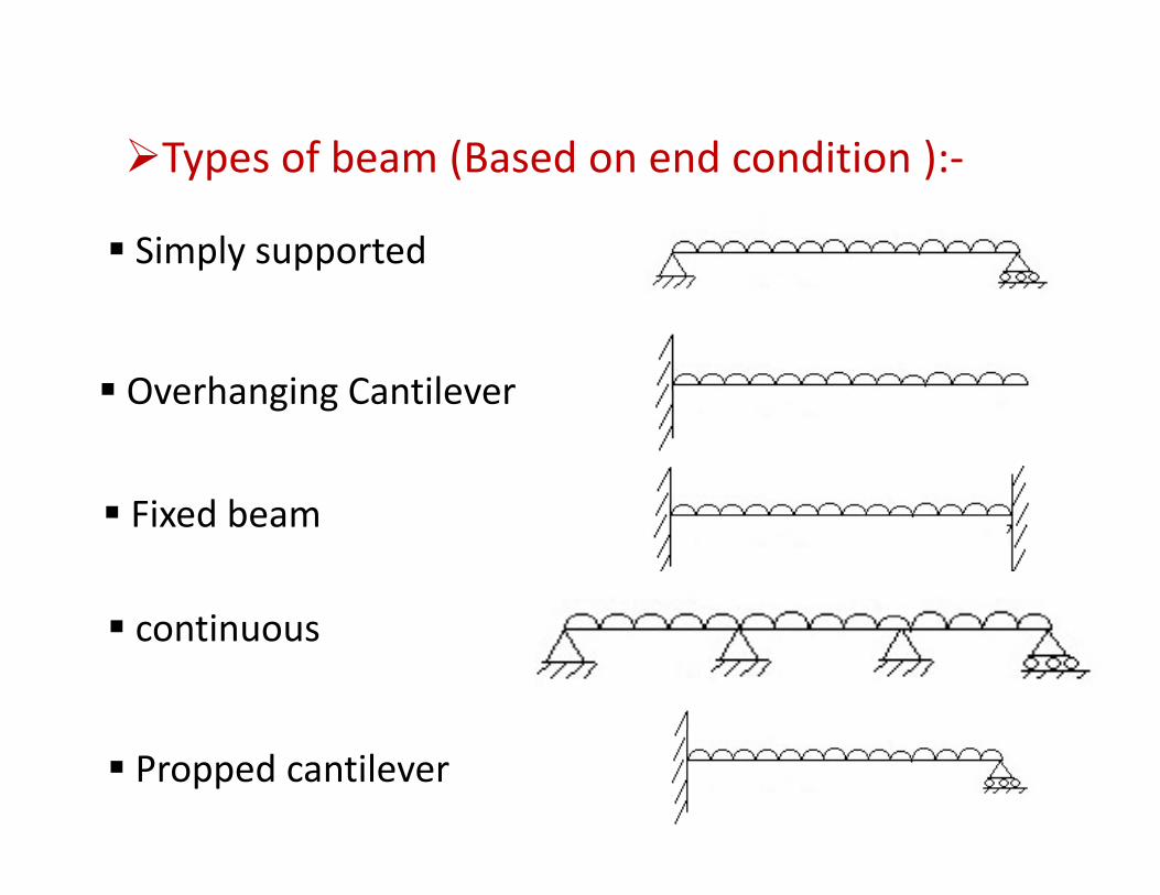
Types of beam (Based on end condition ):‐Types of beam (Based on end condition ):
Simply supported
Overhanging CantileverOverhanging Cantilever
Fi d bFixed beam
ticontinuous
Propped cantilever
Typical name of beam :Joist :‐ A closely spaced beam supporting floors or, roof of
Building but not supporting the other beam .
Larger beam are used for supporting a number of joists.Th ll d Gi dThey are called Girders.
Beam are also used to carry roof loads in trusses TheseBeam are also used to carry roof loads in trusses. These Beam are called Purlins.
Stringer :‐ In building , beams supporting stair steps, in bridges a longitudinal beam supporting deck floor and Supported by floor beam.
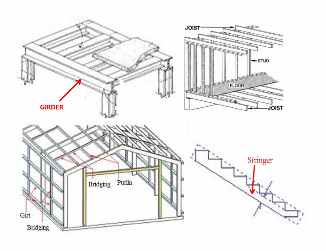
GIRDER
Spandrel beam :‐ In a building a beam on the outsideSpandrel beam : In a building a beam on the outsidePerimeter of a floor, supporting the exterior walls andOutside edge of the floors.
A horizontal beam spanning the wall columns of industrialB ildi d t t ll i i ll d GIRTBuilding used to support wall coverings is called a GIRT.
A roof beam usually supported by purlins is called a RafterA roof beam usually supported by purlins is called a Rafter.Beam are also used to support the loads from the masonryOver the openings. Such types of beam are called Lintels.
Floor beam:‐ A major beam supporting other beams orb ld l h b b dJoints in a building; also the transverse beam in bridge.
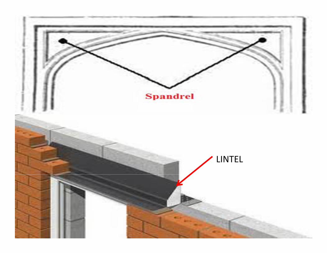
LINTEL
Mode of failure of beam :‐
Primary mode of failure of beams are as follows :
Bending failure :‐ Due to crushing of compression flange or fracture of tension flange.or fracture of tension flange.
Shear failure :‐ Due to buckling of web near location of high shear force.
D fl ti f il St t i d t b f ilDeflection failure :‐ Structure is assumed to be fail orunsuitable if excessive deflection occur.
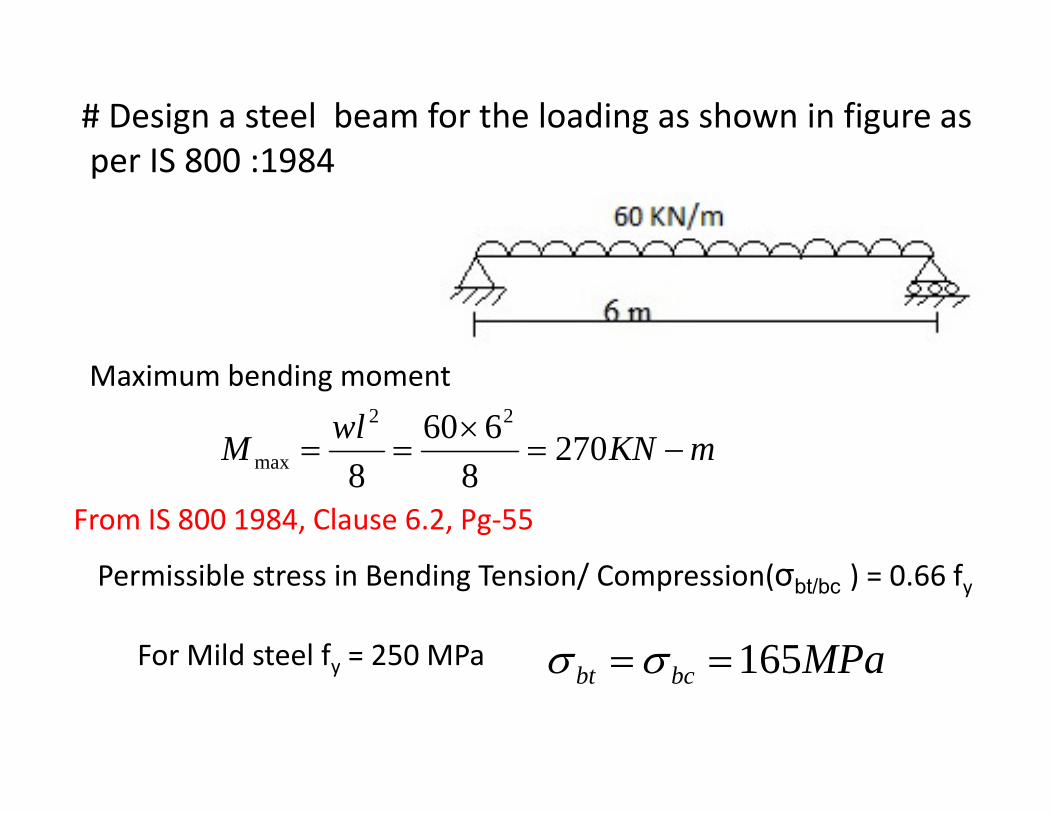
# Design a steel beam for the loading as shown in figure asIS 800 1984per IS 800 :1984
Maximum bending moment
mKNwlM −=×
== 270660 22
mKNM 27088max
From IS 800 1984, Clause 6.2, Pg‐55
Permissible stress in Bending Tension/ Compression(σbt/bc ) = 0.66 fy
For Mild steel fy = 250 MPa MPa165==σσFor Mild steel fy 250 MPa MPabcbt 165==σσ
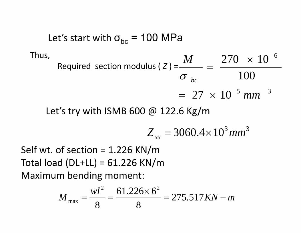
Let’s start with σbc = 100 MPabc
Thus,Required section modulus ( Z ) =
6
10010270M ×
=
351027
100
mmbc
×=
σ
Let’s try with ISMB 600 @ 122.6 Kg/m
331043060 mmZ ×104.3060 mmZxx ×=Self wt. of section = 1.226 KN/mT t l l d (DL+LL) 61 226 KN/Total load (DL+LL) = 61.226 KN/mMaximum bending moment:
wl ×622661 22
mKNwlM −=×
== 517.2758
6226.618max
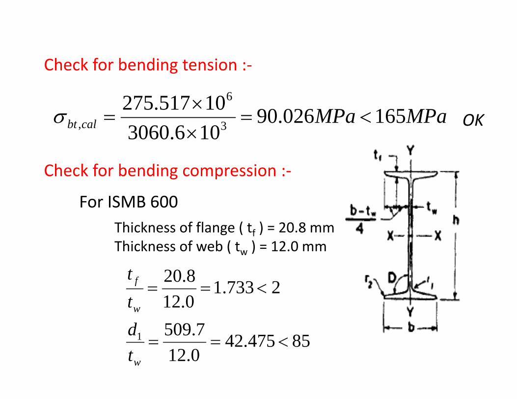
Check for bending tension :‐
MPaMPacalbt 165026.9010517.2753
6
<=×
=σ OKcalbt 106.3060 3, ×OK
Check for bending compression :‐Check for bending compression :
For ISMB 600Thi k f fl ( t ) 20 8Thickness of flange ( tf ) = 20.8 mmThickness of web ( tw ) = 12.0 mm
820t
7509
2733.10.128.20
<==w
f
dtt
85475.420.127.5091 <==
wtd
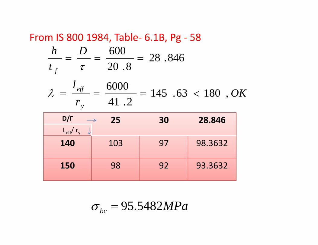
From IS 800 1984, Table‐ 6.1B, Pg ‐ 58D
th
f
846.288.20
600===
τ
OKrl
y
eff ,18063.1452.41
6000<===λ
y
D/Γ 25 30 28.846Leff/ ry
140 103 97 98.3632
150 98 92 93.3632
MPabc 5482.95=σ
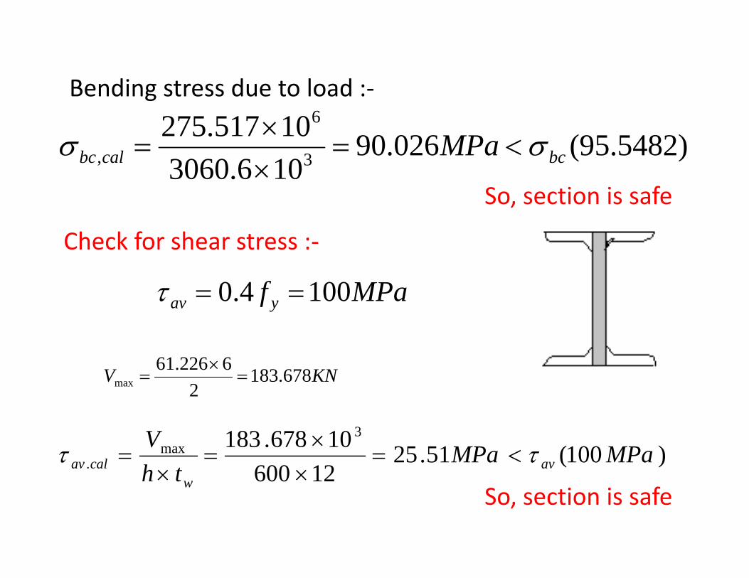
Bending stress due to load :‐
)5482.95(026.90106.306010517.275
3
6
, bccalbc MPa σσ <=××
=
So, section is safe
Check for shear stress :‐
MPaf yav 1004.0 ==τ
KNV 678.1832
6226.61max =
×=
)100(51.2512600
10678.183 3max
. MPaMPath
Vavcalav ττ <=
××
=×
=12600th w ××
So, section is safe
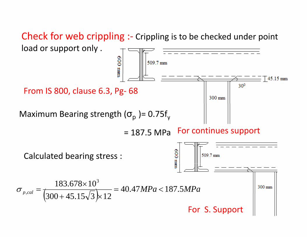
Check for web crippling :‐ Crippling is to be checked under pointload or support only .
From IS 800, clause 6.3, Pg‐ 68
For continues support
Maximum Bearing strength (σp )= 0.75fy
= 187 5 MPa pp= 187.5 MPa
Calculated bearing stress :
( ) MPaMPacalp 5.18747.4012314300
10678.183 3
<=×
=σ
For S. Support
( )calp 12315.45300, ×+
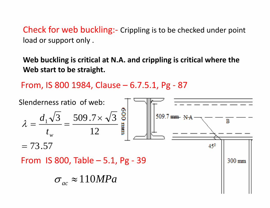
Check for web buckling:‐ Crippling is to be checked under pointl d t lload or support only .
Web buckling is critical at N.A. and crippling is critical where theWeb start to be straight.
From, IS 800 1984, Clause – 6.7.5.1, Pg ‐ 87
Slenderness ratio of web:
375093 ×d
577312
37.50931 ×==
wtdλ
57.73=From IS 800, Table – 5.1, Pg ‐ 39
MPaac 110≈σ
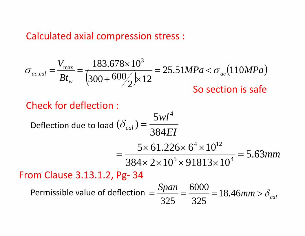
Calculated axial compression stress :
( ) ( )MPaMPaVaccalac 11051.25600
10678.183 3max σσ <=
×== ( ) ( )
Bt acw
calac 122600300.
×+So section is safe
Ch k f d fl tiCheck for deflection :
Deflection due to loadEI
wlcal 384
5)(4
=δ
mm
EI
63.51091813102384
106226.615384
45
124
=××××
×××=
1091813102384 ××××
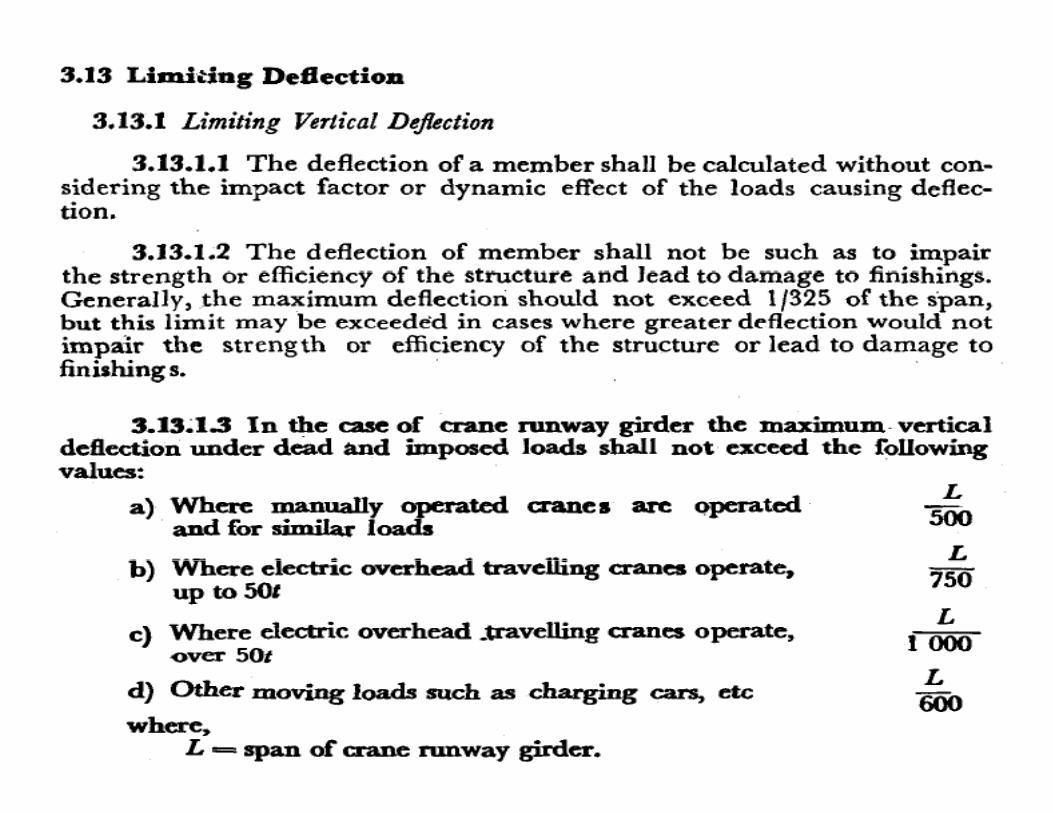
Permissible value of deflection
From Clause 3.13.1.2, Pg‐ 34
mmSpan δ>46186000Permissible value of deflection calmm δ>=== 46.18325325