Embed Size (px)
Citation preview

LRFDLRFD--Steel DesignSteel Design LRFDLRFD--Steel DesignSteel Design

Chapter Chapter 55

55..11 INTRODUCTIONINTRODUCTION
BeamsBeams:: StructuralStructural membersmembers thatthat supportsupport transversetransverse loadsloads andand areare
thereforetherefore subjectedsubjected primarilyprimarily toto flexure,flexure, oror bendingbending..
structuralstructural membermember isis consideredconsidered toto bebe aa beambeam ifif itit isis loadedloaded soso
asas toto causecause bendingbending
CommonlyCommonly usedused crosscross--sectionalsectional shapesshapes includeinclude thethe WW--,, SS--,, andand
MM--shapesshapes.. ChannelChannel shapesshapes areare sometimessometimes usedused..
DoublyDoubly symmetricsymmetric shapesshapes suchsuch asas thethe standardstandard rolledrolled WW--,, MM--,,
andand SS--shapesshapes areare thethe mostmost efficientefficient..
AISCAISC SpecificationSpecification distinguishesdistinguishes beamsbeams fromfrom plateplate girdersgirders onon
thethe basisbasis ofof thethe widthwidth--thicknessthickness ratioratio ofof thethe webweb..
Both a hotBoth a hot--rolled shape and a built up shape along with the rolled shape and a built up shape along with the
dimensions to be used for the widthdimensions to be used for the width--thickness ratios.thickness ratios.
IfIf
thenthen thethe membermember isis toto bebe treatedtreated asas aa beam,beam, regardlessregardless ofof
whetherwhether itit isis aa rolledrolled shapeshape oror isis builtbuilt--upup..

If If
thenthen thethe membermember isis consideredconsidered toto bebe aa plateplate girdergirder..
ForFor beams,beams, thethe basicbasic relationshiprelationship betweenbetween loadload effectseffects andand
strengthstrength isis
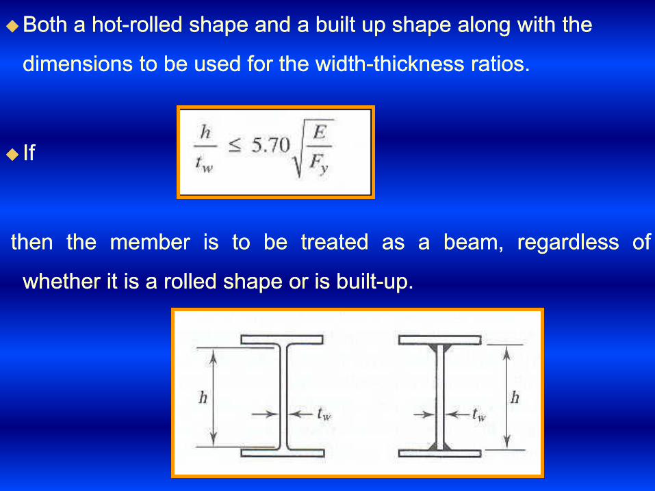
55..2 2 BENDING STRESS AND THE PLASTIC MOMENT:BENDING STRESS AND THE PLASTIC MOMENT:
––Consider the beam which is oriented so that bending is about Consider the beam which is oriented so that bending is about
the major principal axis.the major principal axis.
––The stress at any point can be found from the flexure formula:The stress at any point can be found from the flexure formula:
––Where M is the bending moment at the cross section underWhere M is the bending moment at the cross section under
consideration, y is the perpendicularconsideration, y is the perpendicular distance distance

For maximum stress, Equation takes the form:For maximum stress, Equation takes the form:
––wherewhere cc isis thethe perpendicularperpendicular distancedistance fromfrom thethe neutralneutral axisaxis toto
thethe extremeextreme fiber,fiber, andand SSxx isis thethe elasticelastic sectionsection modulusmodulus ofof thethe
crosscross sectionsection

Equations are valid as long as the loads are small enough that Equations are valid as long as the loads are small enough that
the material remains within its linear the material remains within its linear elastic rangeelastic range. For structural . For structural
steel, this means that the stress steel, this means that the stress ffmaxmax must not exceed must not exceed FyFy and and
that the bending moment must not exceedthat the bending moment must not exceed
MMyy = = FFyy**SSxx
Where My is the bending moment that brings the beam to the Where My is the bending moment that brings the beam to the
point of yielding.point of yielding.
Once yielding begins, the distribution of stress on the cross Once yielding begins, the distribution of stress on the cross
section will no longer be linear, and yielding will progress from section will no longer be linear, and yielding will progress from
the extreme fiber toward the neutral axis.the extreme fiber toward the neutral axis.

tt
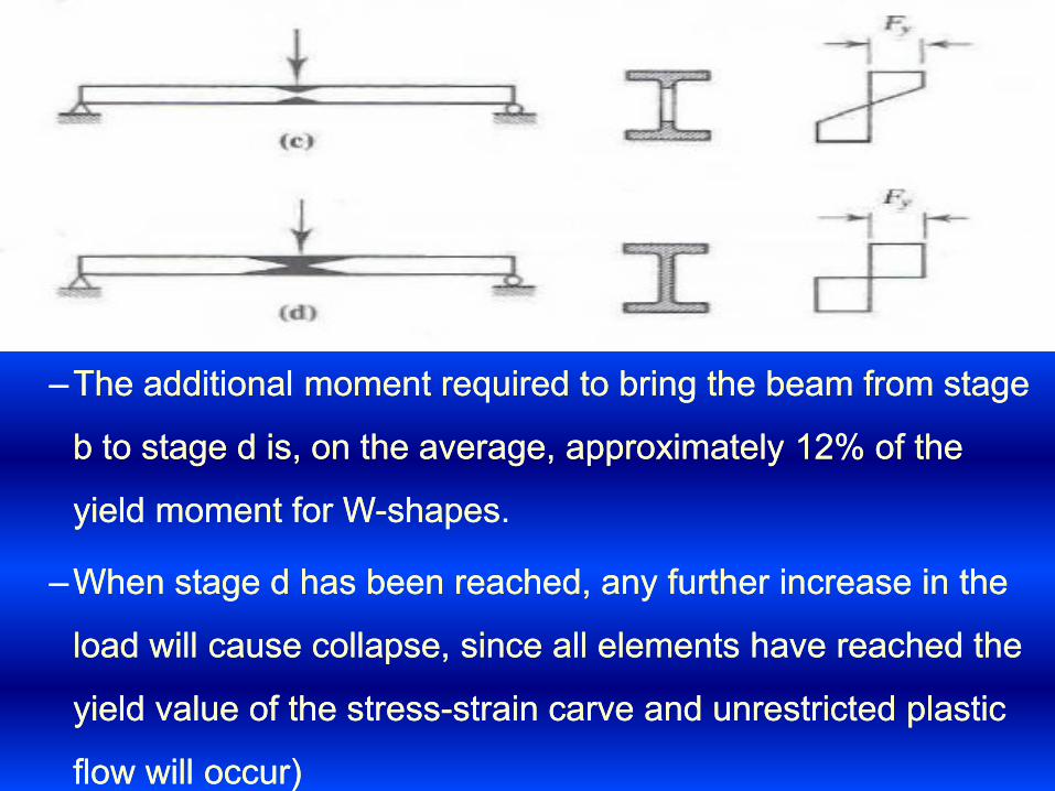
––The additional moment required to bring the beam from stage The additional moment required to bring the beam from stage
b to stage d is, on the average, approximately b to stage d is, on the average, approximately 1212% of the % of the
yield moment for Wyield moment for W--shapes. shapes.
––When stage d has been reached, any further increase in the When stage d has been reached, any further increase in the
load will cause collapse, since all elements have reached the load will cause collapse, since all elements have reached the
yield value of the stressyield value of the stress--strain carve and unrestricted plastic strain carve and unrestricted plastic
flow will occur)flow will occur)

A plastic hinge is said to have formed at the center of the beam.A plastic hinge is said to have formed at the center of the beam.
At this moment the beam consider in an unstable mechanism.At this moment the beam consider in an unstable mechanism.
The mechanism motion will be as shown The mechanism motion will be as shown
Structural analysis based on a consideration of collapse Structural analysis based on a consideration of collapse
mechanism is called plastic analysis.mechanism is called plastic analysis.

TheThe plasticplastic momentmoment capacity,capacity, whichwhich isis thethe momentmoment requiredrequired toto
formform thethe plasticplastic hinge,hinge, cancan easilyeasily bebe computedcomputed fromfrom aa
considerationconsideration ofof thethe correspondingcorresponding stressstress distribution,distribution, FromFrom
equilibriumequilibrium ofof forcesforces::
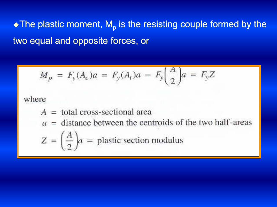
The plastic moment, MThe plastic moment, Mpp is the resisting couple formed by the is the resisting couple formed by the
two equal and opposite forces, ortwo equal and opposite forces, or

Example Example 55..11: For the built: For the built--up shape, determine (a) the elastic up shape, determine (a) the elastic
section modulus S and the yield moment My and (b) the plastic section modulus S and the yield moment My and (b) the plastic
section modulus Z and the plastic moment Mpsection modulus Z and the plastic moment Mp--Bending is about Bending is about
the xthe x--axis, and the steel is Aaxis, and the steel is A572 572 Grade Grade 5050..
SolutionSolution
BecauseBecause ofof symmetry,symmetry, thethe elasticelastic
neutralneutral axisaxis isis locatedlocated atat midmid--depthdepth ofof
thethe crosscross sectionsection.. TheThe momentmoment ofof inertiainertia
ofof thethe crosscross sectionsection cancan bebe foundfound byby
usingusing thethe parallelparallel axisaxis theorem,theorem, andand thethe
resultsresults ofof thethe calculationscalculations areare
summarizedsummarized inin thethe nextnext tabletable..

Answer (A)Answer (A)
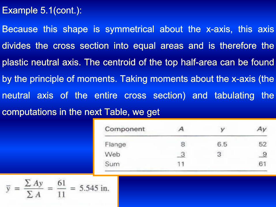
ExampleExample 55..11(cont(cont..))::
BecauseBecause thisthis shapeshape isis symmetricalsymmetrical aboutabout thethe xx--axis,axis, thisthis axisaxis
dividesdivides thethe crosscross sectionsection intointo equalequal areasareas andand isis thereforetherefore thethe
plasticplastic neutralneutral axisaxis.. TheThe centroidcentroid ofof thethe toptop halfhalf--areaarea cancan bebe foundfound
byby thethe principleprinciple ofof momentsmoments.. TakingTaking momentsmoments aboutabout thethe xx--axisaxis (the(the
neutralneutral axisaxis ofof thethe entireentire crosscross section)section) andand tabulatingtabulating thethe
computationscomputations inin thethe nextnext Table,Table, wewe getget

answeranswer

Example Example 55..2 2 ::
SolutionSolution


55..3 3 STABILITYSTABILITY::
––IfIf aa beambeam cancan bebe countedcounted onon toto remainremain stablestable upup toto thethe fullyfully plasticplastic
condition,condition, thethe nominalnominal momentmoment strengthstrength cancan bebe takentaken asas::
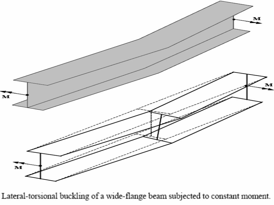
––WhenWhen aa beambeam bend,bend, thethe compressioncompression regionregion isis analogousanalogous toto aa
column,column, andand inin aa mannermanner similarsimilar toto aa column,column, itit willwill bucklebuckle ifif thethe
membermember isis slenderslender enoughenough.. UnlikeUnlike aa columncolumn however,however, thethe
compressioncompression portionportion ofof thethe crosscross sectionsection isis restrainedrestrained byby thethe tensiontension
portionportion.. andand thethe outwardoutward deflectiondeflection ((flexuralflexural bucklingbuckling)) isis accompaniedaccompanied
byby twistingtwisting ((torsiontorsion))..

Local buckling of flange due to compressive stress (σ)
ThisThis formform ofof instabilityinstability isis calledcalled laterallateral--tensionaltensional bucklingbuckling ((LTBLTB))..
LateralLateral tensionaltensional bucklingbuckling cancan bebe preventedprevented byby bracingbracing thethe beambeam
againstagainst twistingtwisting atat sufficientlysufficiently closeclose intervalsintervals

This can be accomplished with either of two types of stability This can be accomplished with either of two types of stability
bracing:bracing:
Lateral bracingLateral bracing: which prevents lateral translation. should be : which prevents lateral translation. should be
applied as close to the compression flange as possible.applied as close to the compression flange as possible.
Tensional bracing Tensional bracing :prevents twist directly.:prevents twist directly.
The moment strength depends in part on the unbraced length, The moment strength depends in part on the unbraced length,
which is the distance between points of bracing.which is the distance between points of bracing.
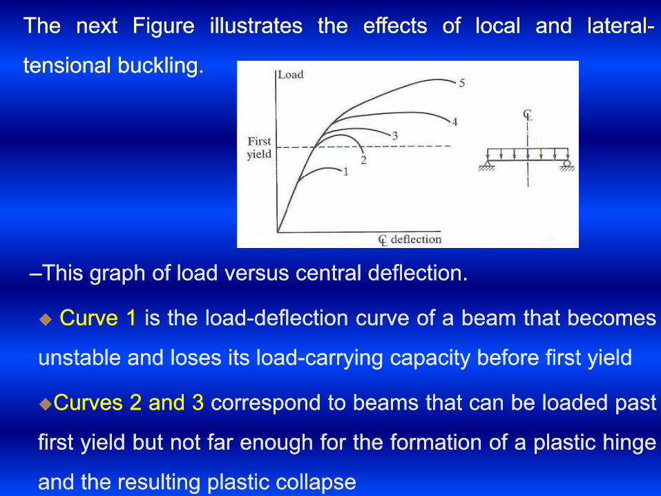
––ThisThis graphgraph ofof loadload versusversus centralcentral deflectiondeflection..
CurveCurve 11 isis thethe loadload--deflectiondeflection curvecurve ofof aa beambeam thatthat becomesbecomes
unstableunstable andand losesloses itsits loadload--carryingcarrying capacitycapacity beforebefore firstfirst yieldyield
CurvesCurves 22 andand 33 correspondcorrespond toto beamsbeams thatthat cancan bebe loadedloaded pastpast
firstfirst yieldyield butbut notnot farfar enoughenough forfor thethe formationformation ofof aa plasticplastic hingehinge
andand thethe resultingresulting plasticplastic collapsecollapse
TheThe nextnext FigureFigure illustratesillustrates thethe effectseffects ofof locallocal andand laterallateral--
tensionaltensional bucklingbuckling..

Curve Curve 44 is for the case of uniform moment over the full length of is for the case of uniform moment over the full length of
the beam.the beam.
curve curve 55 is for a beam with a variable bending momentis for a beam with a variable bending moment
Safe designs can be achieved with beams corresponding to any Safe designs can be achieved with beams corresponding to any
of these curves, but of these curves, but curves curves 1 1 and and 22 represent inefficient use of represent inefficient use of
materialmaterial..
5.4 CLASSIFICATION OF SHAPES
The analytical equations for local buckling of steel plates with The analytical equations for local buckling of steel plates with
various edge conditions and the results from experimental various edge conditions and the results from experimental
investigations have been used to develop limiting slenderness investigations have been used to develop limiting slenderness
ratios for the individual plate elements of the crossratios for the individual plate elements of the cross--sections.sections.

Steel sections are classified as compact, nonSteel sections are classified as compact, non--compact, or compact, or
slender depending upon the slenderness (λ) ratio of the slender depending upon the slenderness (λ) ratio of the
individual plates of the crossindividual plates of the cross--section.section.
11-- Compact section if all elements of crossCompact section if all elements of cross--section have λ ≤ section have λ ≤ λλpp
22-- NonNon--compact sections if any one element of the crosscompact sections if any one element of the cross--section section
has has λλpp ≤ λ ≤ ≤ λ ≤ λλrr
33-- Slender section if any element of the crossSlender section if any element of the cross--section has section has λλrr ≤ λ≤ λ
Where: λ is the widthWhere: λ is the width--thickness ratio, thickness ratio, λλpp is the upper limit for is the upper limit for
compact category and compact category and λλrr is the upper limit for noncompact is the upper limit for noncompact
categorycategory

It is important to note that:It is important to note that:
AA-- If λ ≤ If λ ≤ λλpp, then the individual plate element can develop and , then the individual plate element can develop and
sustain sustain σσyy for large values of ε before local buckling occurs.for large values of ε before local buckling occurs.
BB-- If If λλpp ≤ λ ≤ ≤ λ ≤ λλrr, then the individual plate element can develop , then the individual plate element can develop σσyy
but cannot sustain it before local buckling occurs.but cannot sustain it before local buckling occurs.
CC-- If If λλrr ≤ λ, then elastic local buckling of the individual plate ≤ λ, then elastic local buckling of the individual plate
element occurs.element occurs.
Thus, slender sections cannot develop MThus, slender sections cannot develop Mpp due to elastic local due to elastic local
buckling. Nonbuckling. Non--compact sections can develop Mcompact sections can develop Myy but not Mbut not Mpp before before
local buckling occurs. Only compact sections can develop the local buckling occurs. Only compact sections can develop the
plastic moment Mplastic moment Mpp..

All rolled wideAll rolled wide--flange shapes are compact with the following flange shapes are compact with the following
exceptions, which are nonexceptions, which are non--compact. compact.
WW4040xx174174, W, W1414xx9999, W, W1414xx9090, W, W1212xx6565, W, W1010xx1212, W, W88xx1010, W, W66xx15 15
(made from A(made from A992992))
The definition of λ and the values for The definition of λ and the values for λλpp and and λλrr for the individual for the individual
elements of various crosselements of various cross--sections are given in Table Bsections are given in Table B55..1 1 and and
shown graphically on page shown graphically on page 1616..11--183183. For example,. For example,

Table BTable B55..11, values for , values for λλpp and and λλrr for various crossfor various cross--sections sections
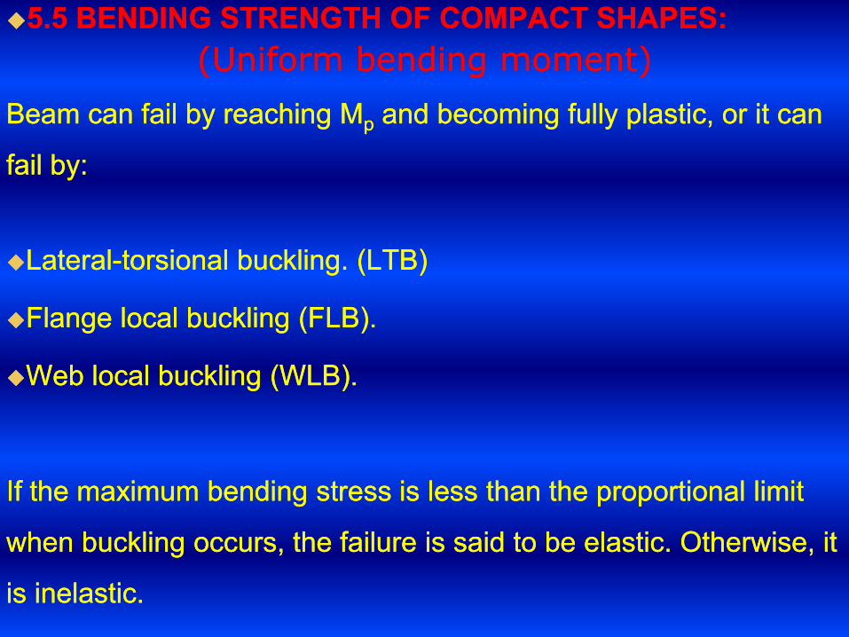
55..5 5 BENDING STRENGTH OF COMPACT SHAPES:BENDING STRENGTH OF COMPACT SHAPES:
(Uniform bending moment)(Uniform bending moment)
Beam can fail by reaching MBeam can fail by reaching Mpp and becoming fully plastic, or it can and becoming fully plastic, or it can
fail by:fail by:
LateralLateral--torsionaltorsional buckling. (LTB)buckling. (LTB)
Flange local buckling (FLB).Flange local buckling (FLB).
Web local buckling (WLB).Web local buckling (WLB).
If the maximum bending stress is less than the proportional limit If the maximum bending stress is less than the proportional limit
when buckling occurs, the failure is said to be elastic. Otherwise, it when buckling occurs, the failure is said to be elastic. Otherwise, it
is inelastic.is inelastic.

compactcompact shapes,shapes, defineddefined asas thosethose whosewhose webswebs areare continuouslycontinuously
connectedconnected toto thethe flangesflanges andand thatthat satisfysatisfy thethe followingfollowing::
TheThe webweb criterioncriterion isis metmet byby allall standardstandard II andand CC shapesshapes listedlisted inin
thethe manual,manual, soso onlyonly thethe flangeflange ratioratio needneed toto bebe checkedchecked..
IfIf thethe beambeam isis compactcompact andand hashas continuouscontinuous laterallateral support,support, oror ifif thethe
unbracedunbraced lengthlength isis veryvery shortshort ,, thethe nominalnominal momentmoment strength,strength, MMnn isis
thethe fullfull plasticplastic momentmoment capacitycapacity ofof thethe shape,shape, MMpp
––ForFor membersmembers withwith inadequateinadequate laterallateral support,support, thethe momentmoment
resistanceresistance isis limitedlimited byby thethe LTBLTB strength,strength, eithereither inelasticinelastic oror elasticelastic..

The first category, laterally supported compact beams is the The first category, laterally supported compact beams is the
simplest casesimplest case
The nominal strength asThe nominal strength as

––ExampleExample 55..33::


TheThe momentmoment strengthstrength ofof compactcompact shapesshapes isis aa functionfunction ofof thethe
unbracedunbraced length,length, LLbb,, defineddefined asas thethe distancedistance betweenbetween pointspoints ofof
laterallateral support,support, oror bracingbracing..
WeWe willwill indicateindicate pointspoints ofof laterallateral supportsupport withwith anan XX asas shownshown inin
thethe FigureFigure::

The relationship between the nominal strength, The relationship between the nominal strength, MMnn,, and the and the
unbraced length, Lunbraced length, Lbb, is shown in the following Figure:, is shown in the following Figure:
If the unbraced length is less than LIf the unbraced length is less than Lpp, the beam is considered to , the beam is considered to
have full lateral support and Mhave full lateral support and Mnn = M= Mpp. .

If LIf Lbb is greater than is greater than LLpp then lateral torsional buckling will occur and then lateral torsional buckling will occur and
the moment capacity of the beam will be reduced below the plastic the moment capacity of the beam will be reduced below the plastic
strength Mstrength Mpp as shown in Figure.as shown in Figure.
The lateralThe lateral--torsional buckling moment (torsional buckling moment (MMnn= = MMcrcr) is a function of the ) is a function of the
laterally unbraced length Lb and can be calculated using the eq.: laterally unbraced length Lb and can be calculated using the eq.:
Where, MWhere, Mn n = moment capacity, L= moment capacity, L b b = laterally unsupported length. = laterally unsupported length.
MMcrcr = critical lateral= critical lateral--torsional buckling moment., E = torsional buckling moment., E = 29000 29000 ksiksi;, G ;, G
= = 1111,,200 200 ksiksi., I., Iy y = moment of inertia about minor or y= moment of inertia about minor or y--axis (inaxis (in44), J = ), J =
torsional constant (intorsional constant (in44) from the AISC manual and C) from the AISC manual and Cw w = warping = warping
constant (inconstant (in66) from the AISC manual.) from the AISC manual.

This equation is valid for ELASTIC lateral torsional buckling only.This equation is valid for ELASTIC lateral torsional buckling only.
That is it will work only as long as the crossThat is it will work only as long as the cross--section is elastic and section is elastic and
no portion of the crossno portion of the cross--section has yielded. section has yielded.
As soon as any portion of the crossAs soon as any portion of the cross--section reaches the Fsection reaches the Fyy , the , the
elastic lateral torsional buckling equation cannot be usedelastic lateral torsional buckling equation cannot be used, , and the and the
moment corresponding to first yield is: moment corresponding to first yield is:
MMrr = S= Sxx (F(Fyy --1010).).
AsAs shownshown inin thethe figure,figure, thethe boundaryboundary betweenbetween elasticelastic andand inelasticinelastic
behaviorbehavior willwill bebe anan unbracedunbraced lengthlength ofof LLrr,, whichwhich isis thethe valuevalue ofof
unbracedunbraced lengthlength thatthat correspondscorresponds toto aa laterallateral--torsionaltorsional bucklingbuckling
momentmoment..

Where: Where: 2
2
1)10(11
)10(
y
y
y
r FXF
XrL
Inelastic behavior of beam is more complicated than elastic Inelastic behavior of beam is more complicated than elastic
behavior, and empirical formulas are often used.behavior, and empirical formulas are often used.

Moment Capacity of beams subjected to nonMoment Capacity of beams subjected to non--uniform B.M. uniform B.M.
The case with uniform bending moment is worst for lateral The case with uniform bending moment is worst for lateral
torsional buckling. torsional buckling.
For cases with nonFor cases with non--uniform B.M, the lateral torsional buckling uniform B.M, the lateral torsional buckling
moment is greater than that for the case with uniform moment. moment is greater than that for the case with uniform moment.
The AISC specification says that:The AISC specification says that:
The lateral torsional buckling moment for nonThe lateral torsional buckling moment for non--uniform B.M case = uniform B.M case =
CC bb x lateral torsional buckling moment for uniform moment case.x lateral torsional buckling moment for uniform moment case.
CC bb is always greater than is always greater than 11..0 0 for nonfor non--uniform bending moment. uniform bending moment.
CC bb is equal to is equal to 11..0 0 for uniform bending moment.for uniform bending moment.
Sometimes, if you cannot calculate or figure out CSometimes, if you cannot calculate or figure out C bb, then it can be , then it can be
conservatively assumed as conservatively assumed as 11..00..

where, where,
MMmaxmax = magnitude of maximum bending moment in L= magnitude of maximum bending moment in Lb b
MMAA = magnitude of bending moment at quarter point of L= magnitude of bending moment at quarter point of Lb b
MMBB = magnitude of bending moment at half point of L= magnitude of bending moment at half point of Lb b
MMCC = magnitude of bending moment at three= magnitude of bending moment at three--quarter point of Lquarter point of Lbb
The moment capacity The moment capacity MMnn for the case of nonfor the case of non--uniform bending uniform bending
moment = moment = MMnn = C= Cbb x {x {MMnn for the case of uniform B.M} ≤ Mfor the case of uniform B.M} ≤ Mpp
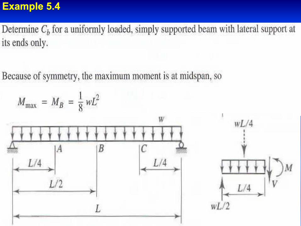
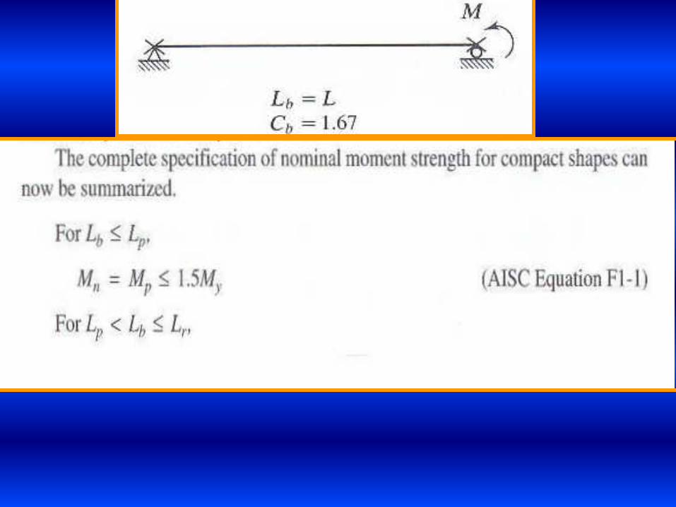
ExampleExample 55..44

The following Figures shows typical values of CThe following Figures shows typical values of Cbb..


Moment capacity versus LMoment capacity versus Lb b
for nonfor non--uniform moment case. uniform moment case.

ExampleExample 55..55::
AnswerAnswer::


55..6 6 BENDING STRENGTH OF NONCOMPACT SHAPESBENDING STRENGTH OF NONCOMPACT SHAPES
Beam may fail by:Beam may fail by:
LateralLateral--torsional buckling. (LTB)torsional buckling. (LTB)
Flange local buckling (FLB).Flange local buckling (FLB).
Web local buckling (WLB).Web local buckling (WLB).
Any of these failures can be in either the elastic range or the Any of these failures can be in either the elastic range or the
inelastic range.inelastic range.
The strength corresponding to each of these three limit states The strength corresponding to each of these three limit states
must be computed.must be computed.
The smallest value will control.The smallest value will control.

For flange local bucklingFor flange local buckling
If If λλpp ≤ λ ≤ ≤ λ ≤ λλrr , the flange is noncompact, buckling will be inelastic, , the flange is noncompact, buckling will be inelastic,
andand
where where
pr
p
rppn MMMM
)(
xyr
y
r
y
p
f
f
SFM
F
E
F
E
t
b
)10(
1083.0,38.0,
2

For flange local bucklingFor flange local buckling
If If λλpp ≤ λ ≤ ≤ λ ≤ λλrr , the flange is noncompact, buckling will be inelastic, , the flange is noncompact, buckling will be inelastic,
andand
where where
pr
p
rppn MMMM
)(
xyr
y
r
y
p
w
SFM
F
E
F
E
t
h
70.5,76.3,
Note that Note that MMrr definition is different for the flange local bucklingdefinition is different for the flange local buckling

Example Example 55..66
a simply supported beam with a span length of a simply supported beam with a span length of 40 40 feet is laterally feet is laterally
supported at its ends and is subjected to supported at its ends and is subjected to 400 400 IbIb/ft D.L and /ft D.L and 1000 1000
IbIb/ft L.L. if /ft L.L. if FFyy ==50 50 ksiksi, is W , is W 14 14 x x 90 90 adequate?adequate?
Solution:Solution:
Factored load = Factored load = 11..22**00..4 4 + + 11..66**11..0 0 = = 22..080 080 kips/ftkips/ft
MMuu=(=(22..08 08 * (* (4040))22)/)/8 8 = = 416416..0 0 ft.kipsft.kips
determine whether the shape is compact, or noncompact, or determine whether the shape is compact, or noncompact, or
slenderslender
2.102
f
f
t
b

since since λλpp ≤ λ ≤ ≤ λ ≤ λλrr , this shape is noncompact. Check the capacity , this shape is noncompact. Check the capacity
based on the limit state of flange local buckling based on the limit state of flange local buckling
3.221050
2900083.0
1083.0
15.950
2900038.038.0
y
r
y
p
F
E
F
E
kipsftSFM
kipsftZFM
xyr
xyp
.7.47612
143)1050()10(
.2.65412
157*50

Check the capacity based on the limit state of LTB. From the Check the capacity based on the limit state of LTB. From the ZZxx
table,table,
LLpp= = 1515..1 1 ft and ft and LLrr = = 3838..4 4 ftft
LLb b = = 4040..0 0 ft > ft > LLrr so failure is by elastic LTB. so failure is by elastic LTB.
From Manual:From Manual:
IIyy = = 362 362 inin4 4 ,, J = J = 44..06 06 inin4 4 andand CCww = = 1616..000 000 inin6 6
for a uniformly loaded, simply supported beam with lateral support for a uniformly loaded, simply supported beam with lateral support
at the ends, Cat the ends, Cbb = = 11..1414
9153.22
15.92.10)7.4762.654(2.654
)(
n
pr
p
rppn
M
MMMM

Because Because 5150 5150 < < 640640..00, LTB controls, and , LTB controls, and
ФMФMnn = = 00..90 90 * * 515515..0 0 = = 464464..0 0 ft.kipsft.kips > M> Muu = = 416416..0 0 ft.kipsft.kips
Since MSince Mu u < < ФMФMnn,, the beam has adequate moment strengththe beam has adequate moment strength
55..7 7 SUMMARY OF MOMENT STRENGTHSUMMARY OF MOMENT STRENGTH
Please read it.Please read it.
)(0.5152.654
.0.515.0.61805421*14.1
16000*36212*40
2900006.4*11200*362*29000
12*4014.1
2
2
OKM
kipsftkipsinM
M
MCIL
EGJEI
LCM
p
n
n
pwy
b
y
b
bn