Embed Size (px)
Citation preview
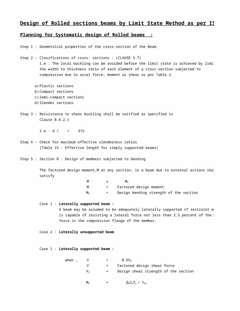
Design of Rolled sections beams by Limit State Method as per IS 800 : 2007 :
Planning for Systematic design of Rolled beams :
Step 1 : Geometrical properties of the cross-section of the Beam.
Step 2 : Classfications of cross- sections : (CLAUSE 3.7)
i.e : The local buckling can be avoided before the limit state is achieved by limiting
the width to thickness ratio of each element of a cross-section subjected to
compression due to axial force, moment or shear as per Table 2.
a) Plastic sections
b) Compact sections
c) Semi-compact sections
d) Slender sections
Step 3 : Reisistance to shear buckling shall be verified as specified in
Clause 8.4.2.1
> 67ε
Step 4 : Check for maximum effective slenderness ratios
(Table 15 : Effective length for simply supported beams)
Step 5 : Section 8 : Design of members subjected to bending
The factored design moment,M at any section, in a beam due to external actions shall
satisfy
M ≤
M = Factored design moment
= Design bending strength of the section
Case 1 : Laterally supported beam :
A beam may be assumed to be adequately laterally supported if restraint member
is capable of resisting a lateral force not less than 2.5 percent of the maximum
force in the compression flange of the member.
Case 2 : Laterally unsupported beam
Case 1 : Laterally supported beam :
when , V <
V = Factored design shear force
= Design shear strength of the section
=
i.e : d / tw
Md
Md
0.6Vd
Vd
Md βbZpfy / ϒmo
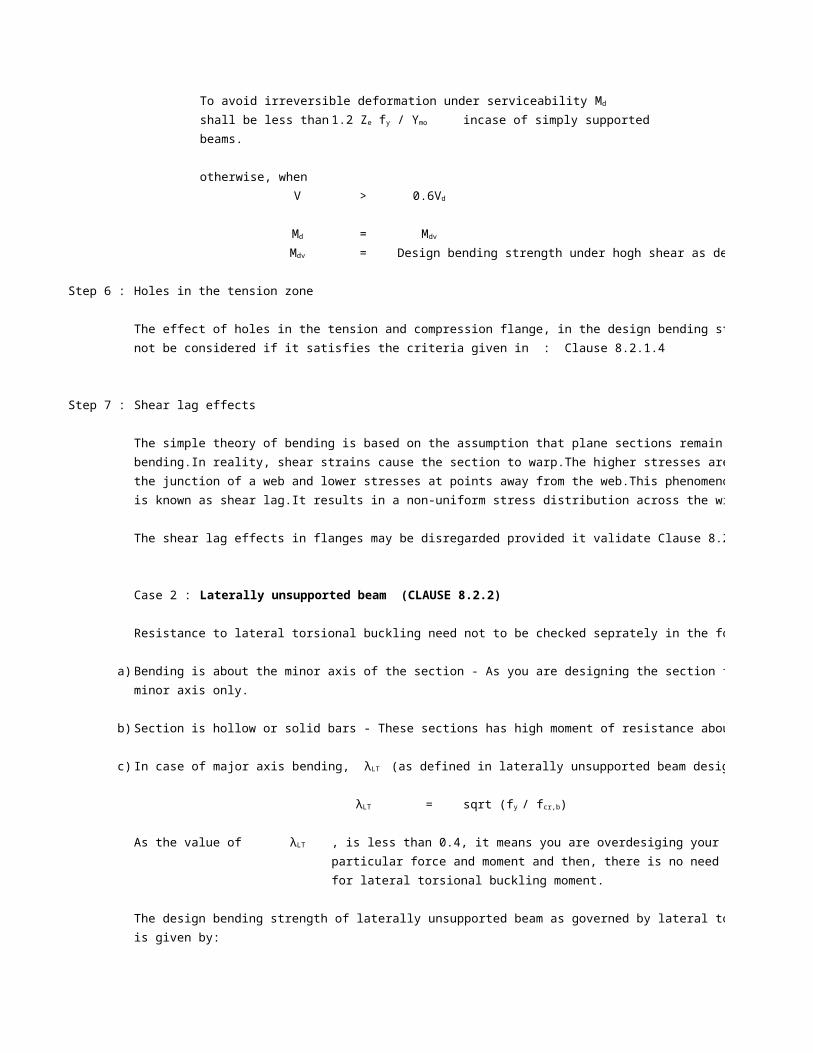
To avoid irreversible deformation under serviceability loads,
shall be less than incase of simply supported
beams.
otherwise, when
V >
=
= Design bending strength under hogh shear as defined in 9.2
Step 6 : Holes in the tension zone
The effect of holes in the tension and compression flange, in the design bending strength need
not be considered if it satisfies the criteria given in : Clause 8.2.1.4
Step 7 : Shear lag effects
The simple theory of bending is based on the assumption that plane sections remain plane after
bending.In reality, shear strains cause the section to warp.The higher stresses are produced near
the junction of a web and lower stresses at points away from the web.This phenomenon
is known as shear lag.It results in a non-uniform stress distribution across the width of the flange.
The shear lag effects in flanges may be disregarded provided it validate Clause 8.2.1.5
Case 2 : Laterally unsupported beam (CLAUSE 8.2.2)
Resistance to lateral torsional buckling need not to be checked seprately in the following cases :
a) Bending is about the minor axis of the section - As you are designing the section for moment about the
minor axis only.
b) Section is hollow or solid bars - These sections has high moment of resistance about both the axis.
c)
=
As the value of , is less than 0.4, it means you are overdesiging your section for a
particular force and moment and then, there is no need to check it
for lateral torsional buckling moment.
The design bending strength of laterally unsupported beam as governed by lateral torsional buckling
is given by:
=
Md
1.2 Ze fy / ϒmo
0.6Vd
Md Mdv
Mdv
In case of major axis bending, λLT (as defined in laterally unsupported beam design) is less than 0.4
λLT sqrt (fy / fcr,b)
λLT
Md βbZpfbd
Step 8 : Check for deflection ( Table 6 of IS 800 defines the deflection limits)
Step 9 : Web buckling and Web crippling (As per 10.11 of Design of steel structures by N.Subramanian)
Web crippling strength of the web also called as the web bearing capacity at supports.
Member subjected to combined forces : (Section 9 of IS 800 2007)
Case 1 : Combined shear and bending :
when , V <
V = Factored design shear force
= Design shear strength of the section
=
otherwise, when
V >
=
= Design bending strength under hogh shear as defined in 9.2
a) Plastic or Compact section :
= ≤
b) Semi-compact section :
=
Case 2 : Combined Axial force and Bending moment : (Clause 9.3)
Under combined axial force and bending moment, section strength as governed by
material failure and member strength
The Indian code (IS 800 : 2007) provisions are based on the Eurocode provisions and the code
requires the following two checks to be performed :
a) Local capacity check
b) Overall buckling check
a) Section strength : (Local capacity check)
i) Palstic & compact sections
0.6Vd
Vd
Md βbZpfy / ϒmo
0.6Vd
Md Mdv
Mdv
Mdv Md - β(Md - Mfd) 1.2 Ze fy / ϒmo
Mdv Ze fy / ϒmo

Members subjected to combined axial force (compression & tension) and bending moment, the
following should be satisfied :
≤ 1
Conservatively,
≤ 1
ii) Semi-compact sections
In the absence of high shear force, semi-compact section design is satisfactory under combined
axial force and bending, if the maximum longitudinal stress under combined axial force and bending,
≤
For cross-section without holes, the above criteria reduces to,
≤ 1
b) Overall member strength : (Overall buckling check)
Members subjected to combined axial force and bending moment shall be checked for overall
buckling failure as given in this section.
i) Bending and axial tension
=
ii) Bending and axial compression
1
1
Important Points :
1) For design purpose, the platform beams shall be designed as a laterally unsupported beam.
As there is no slab over these beams (except roof paltform), there exists an unsupported length
main beam which has to be designed.Laterall bending of main beam will take palce between this
2) When a member is capable of resisting a lateral force not less than 2.5percent of the maximum force
in the compression flange of the member, the member will as a full lateral restraint to the compression
flange of the main beam.
(My / Mndy) 1α + ((Mz / Mndyz)α2
N / Nd + My / Mdy + Mz / Mdz
fx satisfies the following criteria :
fx fy / ϒmo
N / Nd + My / Mdy + Mz / Mdz
Meff (M-Ψ T Zec / A) ≤ Md
P / Pdy + Ky Cmy My / Mdy + KLT Mz / Mdz ≤
P / Pdy + 0.6 Ky Cmy My/Mdy+ KZ Mz / Mdz ≤
Ly , of certain dimensions between two connecting beams which will act as lateral restraint to the
unsupported length Ly.So, the beam will act as a laterally unsupported Beam.
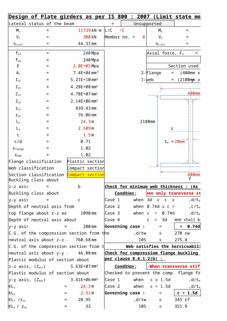
Design of Plate girders as per IS 800 : 2007 (Limit state method) : Beam B1Lateral status of the beam = Unsupported
= 11739 kN-m L/C = 3 = 0 kN-m
= 300 kN = 0 kN
= 44.31 mm = 0.00 mm
= 240 Mpa 0 kN
= 240 MpaE = 2.0E+05 Mpa Section used =
= 7.4E+04 mm² 2-flange = (400mm x 40mm)
= 5.21E+10 1-web = (2100mm x 20mm)
= 4.28E+08
= 4.78E+07 400mm40mm
= 2.14E+06
= 839.43 mm
= 76.06 mm
= 24.3 m 2180mm
= 2.509 m 2100mm =d
c = 1.5 m
c/d = 0.71 20mm
= 1.02
= 1.02
Flange classification = Plastic section 40mm=tfWeb classification = Compact section
Section classification = Compact section 400mm = b
Buckling class about
z-z axis = b Check for minimum web thickness : (As per clause 8.6.1.1(b)
Buckling class about Condition : When only transverse stiffeners are provided
y-y axis = c Case 1: when 3d ≥ c ≥ d ≤
Depth of neutral axis from Case 2: when 0.74d ≤ c < d ≤
top flange about z-z axis = 1090 mm Case 3: when c < 0.74d ≤
Depth of neutral axis about Case 4: c > 3d Web shall be considered as unstiffened
y-y axis = 200 mm Governing case : = c < 0.74d
C.G. of the compression section from the ,d/tw ≤ 270 εw
neutral axis about z-z axis 760.68 mm 105 ≤ 275.4
C.G. of the compression section from the Web satisfies the Serviceability criteria
neutral axis about y-y axis 46.08 mm
Plastic modulus of section about
5.63E+07 Condition : When transverse stiffeners are provided
Plastic modulus of section about Checked to prevent the comp. flange from buckling into the web.
3.41E+06 Case 1: when ≤
= 24.3 m Case 2: when ≤
= 2.51 m Governing case : = c < 1.5d
= 28.95 ,d/tw ≤ 345 εf
= 33 105 ≤ 351.9
Mz My
Vz Member no. = 8 Vh
dv,act dh,act
fyf Axial force, Fa =
fyw
For E250 STEELAt
Izz mm4
Iyy mm4
Zzz mm3
Zyy mm3
rzz
ryy
Lz
Ly
tw =
εflange
εweb
,d/tw 200 εw
,c/tw 200 εw
,d/tw 270 εw
when
Check for compressiom flange buckling requirement : (As per clause 8.6.1.2(b) :
z-z axis, (Zpzz) = mm3
y-y axis, (Zpyy) = mm3c ≥ 1.5d ,d/tw 345 εf
2
KLz c < 1.5d ,d/tw 345 εf
KLy
KLz /rzz
KLy / ryy
z z
y
y

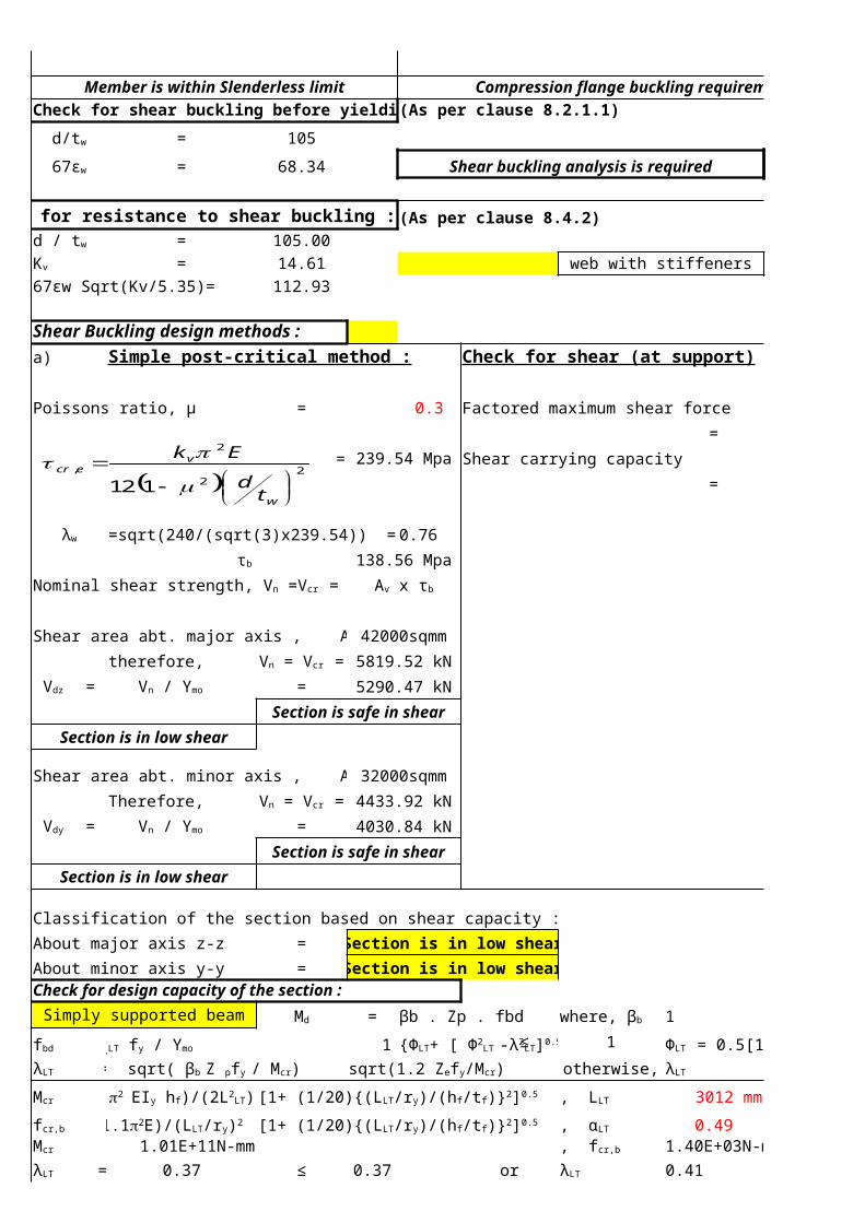
Member is within Slenderless limit Compression flange buckling requirement is satisfiedCheck for shear buckling before yielding : (As per clause 8.2.1.1)
= 105
= 68.34 Shear buckling analysis is required
Check for resistance to shear buckling : (As per clause 8.4.2)= 105.00= 14.61 web with stiffeners
67εw Sqrt(Kv/5.35)= 112.93
Shear Buckling design methods :a) Simple post-critical method : Check for shear (at support)
= 0.3 Factored maximum shear force
= 239.54 Mpa= 1554 kN
Shear carrying capacity
= 5290 kN
Hence safe
=sqrt(240/(sqrt(3)x239.54)) = 0.76
138.56 Mpa
42000sqmm
therefore, 5819.52 kN= 5290.47 kN
Section is safe in shear
Section is in low shear
32000sqmm
Therefore, 4433.92 kN= 4030.84 kN
Section is safe in shear
Section is in low shear
Classification of the section based on shear capacity :
About major axis z-z = Section is in low shear
About minor axis y-y = Section is in low shearCheck for design capacity of the section :
Simply supported beam = βb . Zp . fbd 1 1.1
1 /otherwise,
3012 mm 2140mm
0.491.01E+11N-mm 1.40E+03N-mm
0.37 ≤ 0.37 or 0.41
d/tw
67εw
d / tw
Kv
Poissons ratio, µ
λw
τb =
Nominal shear strength, Vn =Vcr = Av x τb
Shear area abt. major axis , Avz =
Vn = Vcr =Vdz = Vn / ϒmo
Shear area abt. minor axis , Avy =
Vn = Vcr =Vdy = Vn / ϒmo
Md where, βb = , ϒmo =
fbd = χLT fy / ϒmo , χLT = {ФLT+ [ Ф2LT -λ2
LT]0.5} ≤ 1 , ФLT = 0.5[1 + αLT + ( λLT - 0.2) + λLT 2]λLT = sqrt( βb Z pfy / Mcr) ≤ sqrt(1.2 Zefy/Mcr) λLT = sqrt( fy/fcr,b)
Mcr = (p2 EIy hf)/(2L2LT) [1+ (1/20){(LLT/ry)/(hf/tf)}2]0.5 , LLT = ,hf =
fcr,b = (1.1p2E)/(LLT/ry)2 [1+ (1/20){(LLT/ry)/(hf/tf)}2]0.5 , αLT =Mcr = , fcr,b = λLT = λLT =
2
2
2
,
112
w
vecr
td
Ek
p
0.37 Member may be designed as laterally supported beamTherefore, λLT =
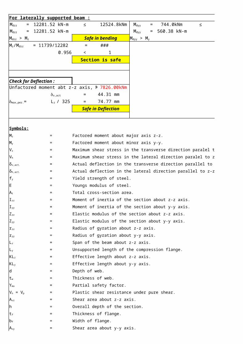
For laterally supported beam :
12281.52 kN-m ≤ 12524.8kNm 744.0kNm ≤ 560.4kNm12281.52 kN-m 560.38 kN-m
Safe in bending Safe in bending
= 11739/12282 = 0.956
0.956 < 1
Section is safe
Check for Deflection :Unfactored moment abt z-z axis, M = 7826.00kNm
= 44.31 mm
= 74.77 mm
Safe in Deflection
Symbols:
= Factored moment about major axis z-z.
= Factored moment about minor axis y-y.
= Maximum shear stress in the transverse direction paralel to y-y axis.
= Maximum shear stress in the lateral direction paralel to z-z axis.
= Actual deflection in the transverse direction parallel to y-y axis.
= Actual deflection in the lateral direction parallel to z-z axis.
= Yield strength of steel.
E = Youngs modulus of steel.
= Total cross-section area.
= Moment of inertia of the section about z-z axis.
= Moment of inertia of the section about y-y axis.
= Elastic modulus of the section about z-z axis.
= Elastic modulus of the section about y-y axis.
= Radius of gyration about z-z axis.
= Radius of gyration about y-y axis.
= Span of the beam about z-z axis.
= Unsupported length of the compression flange.
= Effective length about z-z axis.
= Effective length about y-y axis.
d = Depth of web.
= Thickness of web.
= Partial safety factor.
= Plastic shear resistance under pure shear.
= Shear area about z-z axis.
h = Overall depth of the section.
= Thickness of flange.
= Width of flange.
= Shear area about y-y axis.
Mdzz = Mdyy =Mdzz = Mdyy =
Mdzz > Mz Mdyy > My
Mz/Mdzz
dv,act
dmax,per.= Lz / 325
Mz
My
Vz
Vh
δv,act.
δh,act.
fy
At
Izz
Iyy
Zzz
Zyy
rzz
ryy
Lz
Ly
KLz
KLy
tw
ϒmo
Vn = Vp
Avz
tf
bf
Avy

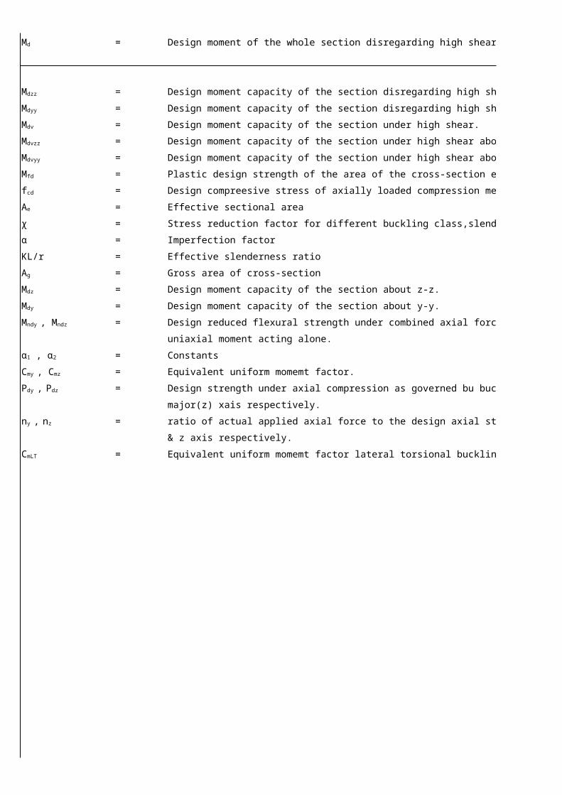
= Design moment of the whole section disregarding high shear force effect.
= Design moment capacity of the section disregarding high shear force effect about z-z.
= Design moment capacity of the section disregarding high shear force effect about y-y.
= Design moment capacity of the section under high shear.
= Design moment capacity of the section under high shear about z-z axis.
= Design moment capacity of the section under high shear about y-y axis.
= Plastic design strength of the area of the cross-section excluding the shear area.
= Design compreesive stress of axially loaded compression members.
= Effective sectional area
χ = Stress reduction factor for different buckling class,slenderness ratio and yield stress.
α = Imperfection factor
KL/r = Effective slenderness ratio
= Gross area of cross-section
= Design moment capacity of the section about z-z.
= Design moment capacity of the section about y-y.
= Design reduced flexural strength under combined axial force and the respective
uniaxial moment acting alone.
= Constants
= Equivalent uniform momemt factor.
= Design strength under axial compression as governed bu buckling about minor(y) &
major(z) xais respectively.
= ratio of actual applied axial force to the design axial strength for buckling about the y
& z axis respectively.
= Equivalent uniform momemt factor lateral torsional buckling.
Md
Mdzz
Mdyy
Mdv
Mdvzz
Mdvyy
Mfd
fcd
Ae
Ag
Mdz
Mdy
Mndy , Mndz
α1 , α2
Cmy , Cmz
Pdy , Pdz
ny , nz
CmLT

Design of Plate girders as per IS 800 : 2007 (Limit state method) : Beam B3Lateral status of the beam = Unsupported
= 381 kN-m L/C = 3 = 0 kN-m
= 77 kN Member no. = 54 = 0 kN
= 13.89 mm = 0.00 mm
= 250 Mpa 0 kN
= 250 MpaE = 2.0E+05 Mpa Section used =
= 1.5E+04 mm² 2-flange = (300mm x 16mm)
= 6.57E+08 1-web = (465mm x 12mm)
= 7.21E+07
= 2.65E+06 300mm16mm
= 4.80E+05
= 208.11 mm
= 68.9 mm
= 8.48 m 497mm
= 2.7 m 465mm =d
c = 1.35 m
c/d = 2.9 12mm
= 1
= 1
Flange classification = Compact section 16mm=tfWeb classification = Plastic section
Section classification = Plastic section 300mm = b
Buckling class about
z-z axis = b Check for minimum web thickness : (As per clause 8.6.1.1(b)
Buckling class about Condition : When only transverse stiffeners are provided
y-y axis = c Case 1: when 3d ≥ c ≥ d ≤
Depth of neutral axis from Case 2: when 0.74d ≤ c < d ≤
top flange about z-z axis = 248.5 mm Case 3: when c < 0.74d ≤
Depth of neutral axis about Case 4: c > 3d Web shall be considered as unstiffened
y-y axis = 150 mm Governing case : = 3d ≥ c ≥ d
C.G. of the compression section from the ,d/tw ≤ 200 εw
neutral axis about z-z axis 194.83 mm 38.75 ≤ 200
C.G. of the compression section from the Web satisfies the Serviceability criteria
neutral axis about y-y axis 48.53 mm
Plastic modulus of section about
2.96E+06 Condition : When transverse stiffeners are provided
Plastic modulus of section about Checked to prevent the comp. flange from buckling into the web.
7.37E+05 Case 1: when ≤
= 8.48 m Case 2: when ≤
= 2.7 m Governing case : = c ≥ 1.5d
= 40.75 ,d/tw ≤ 345 εf2
= 39.19 38.75 ≤ 345
Mz My
Vz Vh
dv,act dh,act
fyf Axial force, Fa =
fyw
For E250 STEELAt
Izz mm4
Iyy mm4
Zzz mm3
Zyy mm3
rzz
ryy
Lz
Ly
tw =
εflange
εweb
,d/tw 200 εw
,c/tw 200 εw
,d/tw 270 εw
when
Check for compressiom flange buckling requirement : (As per clause 8.6.1.2(b) :
z-z axis, (Zpzz) = mm3
y-y axis, (Zpyy) = mm3c ≥ 1.5d ,d/tw 345 εf
2
KLz c < 1.5d ,d/tw 345 εf
KLy
KLz /rzz
KLy / ryy
z z
y
y
Member is within Slenderless limit Compression flange buckling requirement is satisfiedCheck for shear buckling before yielding : (As per clause 8.2.1.1)
= 38.75
= 67 Shear buckling analysis is not required
77.00kN = 0.00kNVn / ϒmo Vn / ϒmo
= 1.1 = 1.1
= 805.40kN = 1385.64kN= 732.18kN = 1259.67kN
Section is safe in shear Section is safe in shearSection is in low shear Section is in low shear
Classification of the section based on shear capacity :
About major axis z-z = Section is in low shear
About minor axis y-y = Section is in low shearCheck for design capacity of the section :
Simply supported beam = βb . Zp . fbd 1 1.1
1 /otherwise,
3240 mm 481mm
0.493.45E+09N-mm 1.04E+03N-mm
0.46 ≤ 0.48 or 0.490.46 Member shall be designed as laterally unsupported beam
For laterally unsupported beam :
0.67 0.87 197.73 Mpa
584.79 kN-m > 381.00kNm 131.03 kN-m > 0kNm
Safe in bending Safe in Bending
= 381/585 = 0.652 Check for shear (at support)0.652 < 1
Section is safe Factored maximum shear force
= 201 kN
Check for Deflection : Shear carrying capacityUnfactored moment abt z-z axis, M = 254.00kNm = 732 kN
= 13.89 mm Hence safe
= 26.09 mm
Safe in Deflection
d/tw
67εw
Factored design shear force,Vz = Factored design shear force,Vy
Design strength,Vdz (abt. major axis)= Design strength, Vdy (about minor axis) =ϒmo ϒmo
Vn = Vp = Avzfyw/sqrt(3) = (d.tw.fyw)/sqrt(3) Vn = Vp = Avy fyw/sqrt(3) = (2b.tf.fyw)/sqrt(3) Vp Vp
Vdz Vdy
Md where, βb = , ϒmo =
fbd = χLT fy / ϒmo , χLT = {ФLT+ [ Ф2LT -λ2
LT]0.5} ≤ 1 , ФLT = 0.5[1 + αLT + ( λLT - 0.2) + λLT 2]λLT = sqrt( βb Z pfy / Mcr) ≤ sqrt(1.2 Zefy/Mcr) λLT = sqrt( fy/fcr,b)
Mcr = (p2 EIy hf)/(2L2LT) [1+ (1/20){(LLT/ry)/(hf/tf)}2]0.5 , LLT = ,hf =
fcr,b = (1.1p2E)/(LLT/ry)2 [1+ (1/20){(LLT/ry)/(hf/tf)}2]0.5 , αLT =Mcr = , fcr,b = λLT = λLT =
Therefore, λLT =
ФLT = , χLT = , fbd =
Mdzz = Mdyy =Mdzz > Mz Mdyy > My
Mz/Mdzz
dv,act
dmax,per.= Lz / 325
unit wt L nos300 16 125.6 8.38 2 631.5168 998.5859465 12 94.2 8.38 1 367.0691
200 20 157 8.38 2 526.264 1007.269457 16 125.6 8.38 1 481.0053
497
0.651
8.6833560.835