Embed Size (px)
Citation preview
6
Design of Model Libraries
Abstract
This chapter gives some guidelines on structuring object-orientedmodel libraries. There are no unique solutions to that problem, butthe idea is to capture key issues and proven solutions in a collec-tion of Design Patterns which can be applied to other modeling prob-lems. Design patterns are an attempt to describe “good practice” in asemi-formal way. Most of the design patterns are applicable to mod-eling in general, but a few are specific to Modelica or thermo-fluidsystems. Examples using Modelica and the ThermoFluid library areused throughout the chapter to illustrate the ideas.
6.1 Introduction
Designing a user-extensible model library is different from building mod-els for one time use. The extensibility is a feature which is not needed tothe same degree in different engineering disciplines. When modeling elec-trical circuits, the models often consist of a large number of components,but each component is described by a few well defined mathematical mod-els, all of which can be made available in an extensive component library.This means that a user typically composes system models from the library,but has no need to alter existing models or write new ones. The situation isdifferent for thermodynamics and process engineering, particularly whenthe scope of the models is as broad as with the ThermoFluid library. Thevariety of heat- and mass-transfer equations and physical property datais broad by itself. The number of possible variants grows exponentiallyif different combinations of these are taken into account as well. Veryoften, modeling requires a problem-specific simplification which does nothold for other problems. Even a huge component library can not coverall variants that a modeler needs for routine modeling use. A library forthermodynamics has to be open for user defined extensions. Designing
177
Chapter 6. Design of Model Libraries
a user-extensible library in such a way that it is powerful, flexible andeasy to understand is a difficult challenge. Object-oriented decompositionof engineering system models into subsystem and component models fol-lows the same decomposition as that of the system itself: the elementsfound on the blueprint or plant flow sheet should be library models. Thisdecomposition has been discussed in [Nilsson, 1993] for process engineer-ing and in [Mühlthaler, 2000] for thermal power plants. Much more codereuse can be achieved when the decomposition is continued to the level ofphysical phenomena. Library design for reuse at the level of phenomenais the topic of this chapter. Examples refer to thermo-fluid applicationsand cover the same models as ThermoFluid. The conceptual structure isemphasized instead of the details of the actual implementation1.
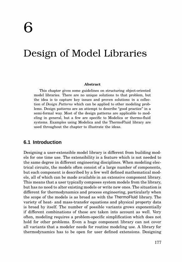
The Design Arch
MaintenanceLevel of Detail
Realization
Component verification
calibration and verificationSystem level Integration, test
Subsystem level integrationand verification
Detailed feature design and implementation
System requirementsmostly static models
Architectural design &system functional design
Preliminary feature designstatic and dynamic models
static and dynamic models
Product verificationand deployment
Design
Design R
efinement
Verification
IntegrationC
alibration
Reuse in next product g
eneration
Spec
ifica
tion
mostly dynamic models
Reu
se in
nex
t des
ign
step
Experience feedback
Figure 6.1 Model reuse along the design arch. The development phases are typicalfor a complex, highly developed product like a car. A similar scheme is sometimesreferred to as design-V.
For an engineer, the foremost goal of a system model is to be mathe-matically correct and to fulfill the requirements in terms of accuracy andsimulation speed. Due to the tedious work necessary to verify and vali-date models, this is a long term process. This model validation is calledcalibration in the automotive industry while the control community refersto the same process as grey-box parameter identification. Some parame-ters are always uncertain, so for every new system the user has to checkagain if the simulation gives a “good enough” picture of reality. Parametershave to be adapted to make simulation model output fit to measurementdata. Many engineers focus on validating and calibrating their modelsand tend to neglect structuring and reuse issues. Proper code structuring
1A detailed and complete documentation is found at http://www.modelica.org/library.
178
6.2 Means for Library Structuring
has proved to increase programming productivity in software engineering.The cyclic nature of modeling in the iterative design of technical productsfrom one generation to the next makes it obvious that reuse will speedup the modeling process substantially. Looking at Figure 6.1 reveals thatthere are two dimensions of reuse:
1. on the same level of detail for the next product generation and
2. along the path of the “Design Arch” in Figure 6.1, spanning differentlevels of detail during the same design cycle.
The second dimension of reuse is more difficult to achieve because themathematical models and the time scales of interest are often differentfor another level of detail of a system model. The granularity of the sys-tem topology can vary along the path of the design process. It is commonpractice to neglect components with little influence on the system dynam-ics.
The main incentive for the development of model libraries is the costsavings from code reuse. The estimations for the cost of software devel-opment vary widely, in a recent report it was claimed that commercialsoftware goes at a tariff of USD 50 – 200 per line of debugged code. Forvalidated code in a modeling language, the numbers are probably higher.This makes it obvious that validated model libraries of industrial rele-vance are a valuable resource.
6.2 Means for Library Structuring
Code structuring has been discussed from a language perspective in Chap-ter 3 and with concrete examples from the ThermoFluid library in Chap-ter 5. Building on those examples, we will now illustrate how the languagetools can be used for model libraries in general. Modeling always offersseveral ways to solve a problem, but in spite of the many possibilities, sim-ilar solutions for the mathematical parts and code structuring are foundrepeatedly even if the modeling languages are different. Building on powerplant library modeling in SMILE and the broader scope of ThermoFluid inModelica, experiences from designing object-oriented model libraries aresummarized.
The advantages of using libraries is to reuse as much well-tested codeas possible in models. This minimizes the need for extended testing. Val-idating and calibrating a model is usually the most time consuming partof the model development process. While there is no way to avoid theso called calibration which consists of adapting the model parameters toplant data via systematic or heuristic methods, testing and internal vali-dation can be substantially reduced when well tested code is reused. For
179
Chapter 6. Design of Model Libraries
simulation of standard problems and plants, it is possible to rely exclu-sively on tested model components. This greatly increases the trust insimulation results.
For the ThermoFluid library, two scenarios of reuse in model develop-ment have been considered:
• Use a partial component and complete the model by filling in themissing pieces.
• Start from scratch and build up a model using as many base classesas make sense.
Clearly, using partial components is faster but the partial models maynot be available. Building models from base classes is more flexible, buttakes longer and needs a thorough understanding of all used classes.When almost complete partial models are used, a developer only needsto know the interfaces and requirements of the missing parts. Readersunfamiliar with object-oriented techniques are recommended to take alook at the glossary in Appendix A in order to get an overview of thevocabulary.
Encapsulation
Information hiding is an important principle to improve the maintainabil-ity of programming code. The idea is that all interaction between modelsoccurs via well-defined interfaces. If this principle is neglected, the inter-dependence between models is likely to increase. That in turn makes itmore difficult to change the system model and both flexibility and main-tainability are lost. Encapsulation of operations is also a property whichmakes it easier to debug faulty programs.
At first sight this may not seem like such an important issue. Experi-ence with typical codes for engineering models in industry which evolvedover many years shows that these codes tend to mutate to almost unmain-tainable spaghetti-code. The main problem in maintainability is undocu-mented interdependence of different parts of the code, which is difficult todetect. This makes it impossible to find an evolutionary solution to adaptthe code to new needs. Many companies depend on the functionality of thecode, but when the last of the original developers leaves the company, acomplete re-engineering has to be undertaken. Proper encapsulation tech-niques make it much more likely that an evolutionary solution simplifiesthe transition to new tools and methods.
Encapsulation in equation based modeling is fundamentally differ-ent from encapsulation in object-oriented programs, where interaction ismostly based on message passing between objects. All operations and thedata they operate on are encapsulated in objects. In equation based mod-eling, all components of a system are linked together via a bipartite graph
180
6.2 Means for Library Structuring
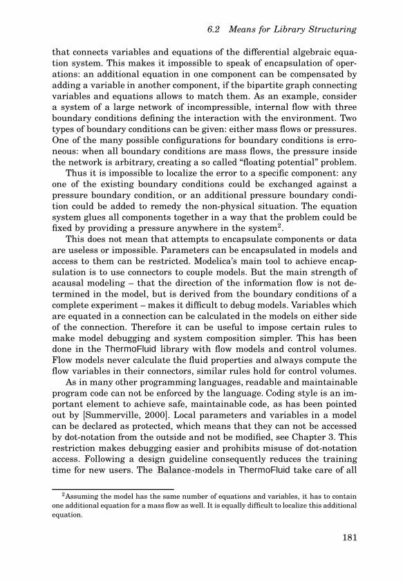
that connects variables and equations of the differential algebraic equa-tion system. This makes it impossible to speak of encapsulation of oper-ations: an additional equation in one component can be compensated byadding a variable in another component, if the bipartite graph connectingvariables and equations allows to match them. As an example, considera system of a large network of incompressible, internal flow with threeboundary conditions defining the interaction with the environment. Twotypes of boundary conditions can be given: either mass flows or pressures.One of the many possible configurations for boundary conditions is erro-neous: when all boundary conditions are mass flows, the pressure insidethe network is arbitrary, creating a so called “floating potential” problem.
Thus it is impossible to localize the error to a specific component: anyone of the existing boundary conditions could be exchanged against apressure boundary condition, or an additional pressure boundary condi-tion could be added to remedy the non-physical situation. The equationsystem glues all components together in a way that the problem could befixed by providing a pressure anywhere in the system2.
This does not mean that attempts to encapsulate components or dataare useless or impossible. Parameters can be encapsulated in models andaccess to them can be restricted. Modelica’s main tool to achieve encap-sulation is to use connectors to couple models. But the main strength ofacausal modeling – that the direction of the information flow is not de-termined in the model, but is derived from the boundary conditions of acomplete experiment – makes it difficult to debug models. Variables whichare equated in a connection can be calculated in the models on either sideof the connection. Therefore it can be useful to impose certain rules tomake model debugging and system composition simpler. This has beendone in the ThermoFluid library with flow models and control volumes.Flow models never calculate the fluid properties and always compute theflow variables in their connectors, similar rules hold for control volumes.
As in many other programming languages, readable and maintainableprogram code can not be enforced by the language. Coding style is an im-portant element to achieve safe, maintainable code, as has been pointedout by [Summerville, 2000]. Local parameters and variables in a modelcan be declared as protected, which means that they can not be accessedby dot-notation from the outside and not be modified, see Chapter 3. Thisrestriction makes debugging easier and prohibits misuse of dot-notationaccess. Following a design guideline consequently reduces the trainingtime for new users. The Balance -models in ThermoFluid take care of all
2Assuming the model has the same number of equations and variables, it has to containone additional equation for a mass flow as well. It is equally difficult to localize this additionalequation.
181
Chapter 6. Design of Model Libraries
interaction of a control volume with its environment. It is important thatno other functionality is implemented there, this would make it more dif-ficult to get an understanding of the role of each model class. Due to theacausal nature of equations it is impossible to enforce encapsulation ofequations in partial components for a library developer who provides par-tial models. A complement that makes model usage easier is to postulaterules for partial library models and document them extensively.
Inheritance and Aggregation
Inheritance is one of the main tools for achieving reuse both in object-oriented software development and modeling. � Inheritance3 ensures thatcode which is common to several models only appears at one place in thesource code, meaning that it only needs to be documented once and main-tained once in case of changes. But overuse of inheritance has a few draw-backs. Experience with the design of both software systems and modellibraries has shown that the total number of classes in overly structuredlibraries becomes large. Understanding is difficult and a long learningtime is the consequence. Large libraries can not be avoided for complexsystems and a broad application scope, but often the large number ofclasses is caused by too extensive use of inheritance. If all variants of aclass of models are derived via inheritance of a base class, many classesare needed. � Aggregation, on the other hand, makes it possible to addsmall units of functionality as needed. The difference in complexity be-comes obvious when combinations of these different units are considered.This will be demonstrated with an example from the ThermoFluid library.The problem is to provide base classes for flow models with one inflowand one outflow e. g., distributed pipe models, but also lumped stirredtank reactors. We consider four optional phenomena which may or maynot be required in the model:
• heat transfer interaction,
• dissipative work interaction from a stirrer,
• chemical reactions,
• diffusion through a membrane adjacent to the control volume.
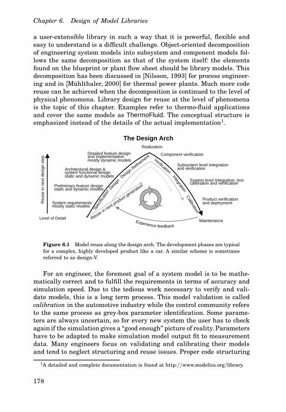
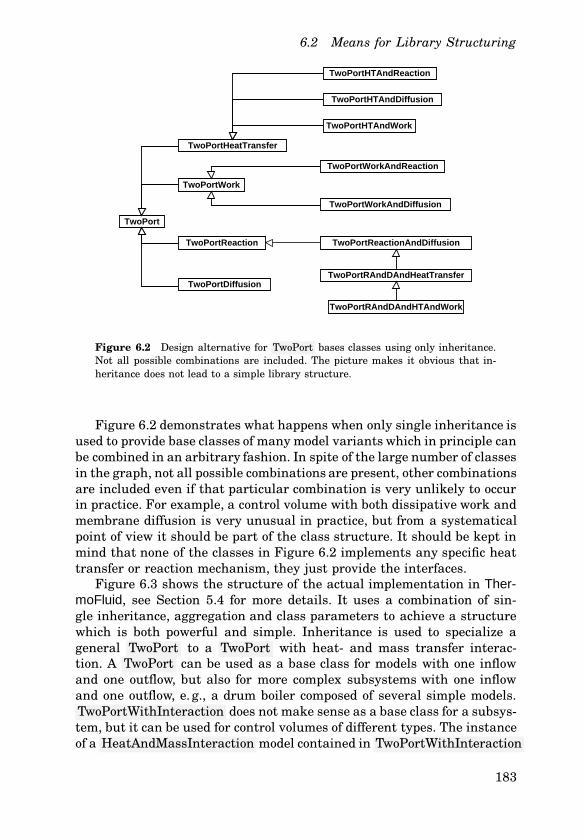
Two alternative designs are considered, one which only uses inheritanceand another option which uses both inheritance and aggregation. Theclass structure of both alternatives is illustrated in Figure 6.2 and Fig-ure 6.3. The usage of the resulting library models is slightly different, sothe figures do not cover the same ranges of model behavior.
3First occurrences of important terms defined in the glossary are marked with a triangleand typeset in � slanted .
182
6.2 Means for Library Structuring
TwoPort
TwoPortHeatTransfer
TwoPortWork
TwoPortReaction
TwoPortDiffusion
TwoPortHTAndReaction
TwoPortHTAndDiffusion
TwoPortHTAndWork
TwoPortWorkAndDiffusion
TwoPortWorkAndReaction
TwoPortReactionAndDiffusion
TwoPortRAndDAndHeatTransfer
TwoPortRAndDAndHTAndWork
Figure 6.2 Design alternative for TwoPort bases classes using only inheritance.Not all possible combinations are included. The picture makes it obvious that in-heritance does not lead to a simple library structure.
Figure 6.2 demonstrates what happens when only single inheritance isused to provide base classes of many model variants which in principle canbe combined in an arbitrary fashion. In spite of the large number of classesin the graph, not all possible combinations are present, other combinationsare included even if that particular combination is very unlikely to occurin practice. For example, a control volume with both dissipative work andmembrane diffusion is very unusual in practice, but from a systematicalpoint of view it should be part of the class structure. It should be kept inmind that none of the classes in Figure 6.2 implements any specific heattransfer or reaction mechanism, they just provide the interfaces.
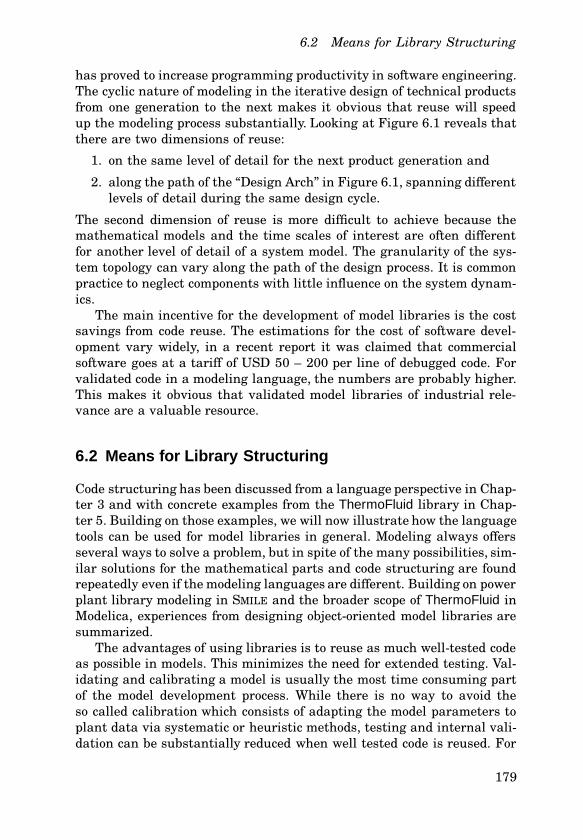
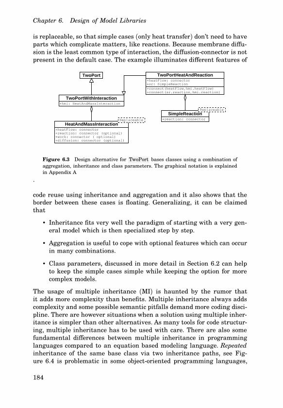
Figure 6.3 shows the structure of the actual implementation in Ther-moFluid, see Section 5.4 for more details. It uses a combination of sin-gle inheritance, aggregation and class parameters to achieve a structurewhich is both powerful and simple. Inheritance is used to specialize ageneral TwoPort to a TwoPort with heat- and mass transfer interac-tion. A TwoPort can be used as a base class for models with one inflowand one outflow, but also for more complex subsystems with one inflowand one outflow, e. g., a drum boiler composed of several simple models.TwoPortWithInteraction does not make sense as a base class for a subsys-tem, but it can be used for control volumes of different types. The instanceof a HeatAndMassInteraction model contained in TwoPortWithInteraction
183
Chapter 6. Design of Model Libraries
is replaceable, so that simple cases (only heat transfer) don’t need to haveparts which complicate matters, like reactions. Because membrane diffu-sion is the least common type of interaction, the diffusion-connector is notpresent in the default case. The example illuminates different features of
TwoPort
TwoPortWithInteraction+hmi: HeatAndMassInteraction
HeatAndMassInteraction+heatFlow: connector+reaction: connector (optional)+work: connector ( optional)+diffusion: connector (optional)
Replaceable
TwoPortHeatAndReaction+heatFlow: connector+sr: SimpleReaction+connect(heatFlow,hmi.heatFlow)+connect(sr.reaction,hmi.reaction)
SimpleReaction+reaction: connector
Replaceable
Figure 6.3 Design alternative for TwoPort bases classes using a combination ofaggregation, inheritance and class parameters. The graphical notation is explainedin Appendix A
.
code reuse using inheritance and aggregation and it also shows that theborder between these cases is floating. Generalizing, it can be claimedthat
• Inheritance fits very well the paradigm of starting with a very gen-eral model which is then specialized step by step.
• Aggregation is useful to cope with optional features which can occurin many combinations.
• Class parameters, discussed in more detail in Section 6.2 can helpto keep the simple cases simple while keeping the option for morecomplex models.
The usage of multiple inheritance (MI) is haunted by the rumor thatit adds more complexity than benefits. Multiple inheritance always addscomplexity and some possible semantic pitfalls demand more coding disci-pline. There are however situations when a solution using multiple inher-itance is simpler than other alternatives. As many tools for code structur-ing, multiple inheritance has to be used with care. There are also somefundamental differences between multiple inheritance in programminglanguages compared to an equation based modeling language. Repeatedinheritance of the same base class via two inheritance paths, see Fig-ure 6.4 is problematic in some object-oriented programming languages,
184
6.2 Means for Library Structuring
VariableRecord+Real a, b, c
Equations_a1+equation_for_a(a)
Equations_a2+equation_for_a(a)
Equations_bc1+equation_for_bc(b,c)
Equations_bc2+equation_for_bc(b,c)
Variant_1 Variant_2
Variant_4Variant_3
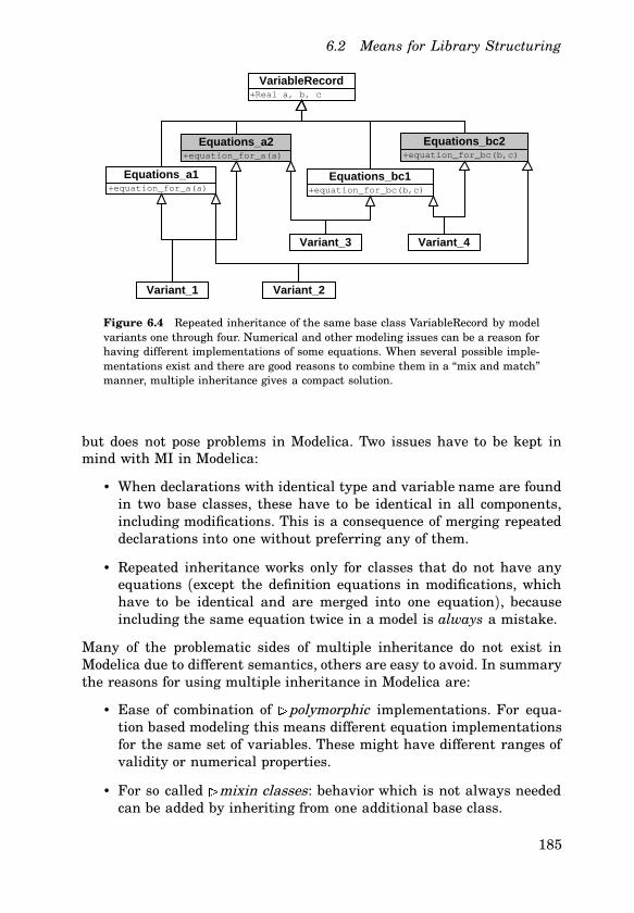
Figure 6.4 Repeated inheritance of the same base class VariableRecord by modelvariants one through four. Numerical and other modeling issues can be a reason forhaving different implementations of some equations. When several possible imple-mentations exist and there are good reasons to combine them in a “mix and match”manner, multiple inheritance gives a compact solution.
but does not pose problems in Modelica. Two issues have to be kept inmind with MI in Modelica:
• When declarations with identical type and variable name are foundin two base classes, these have to be identical in all components,including modifications. This is a consequence of merging repeateddeclarations into one without preferring any of them.
• Repeated inheritance works only for classes that do not have anyequations (except the definition equations in modifications, whichhave to be identical and are merged into one equation), becauseincluding the same equation twice in a model is always a mistake.
Many of the problematic sides of multiple inheritance do not exist inModelica due to different semantics, others are easy to avoid. In summarythe reasons for using multiple inheritance in Modelica are:
• Ease of combination of � polymorphic implementations. For equa-tion based modeling this means different equation implementationsfor the same set of variables. These might have different ranges ofvalidity or numerical properties.
• For so called � mixin classes: behavior which is not always neededcan be added by inheriting from one additional base class.
185
Chapter 6. Design of Model Libraries
• Separate the graphical representation from the implementation. Thiscan be used to customize graphical plant schematics, recreate thevisual appearance of other simulation programs and similar goalswithout affecting the model behavior.
EXAMPLE 1—MULTIPLE INHERITANCE
As an example we compare the use of MI with other design options whichfulfill the same requirements. Alternative designs will be discussed for asituation similar to Figure 6.4, but with more variants. It is assumed thatthree alternatives each exist for four equation parts which all operate onthe same set of twenty variables, giving a total of twelve partial models.The parts implement different physical features. Some of the featuresare optional, some can be implemented in different ways. Each of thepartial models implements a feature with a few equations using a subsetof the common variables. For simplicity it is assumed that all possiblecombinations make sense from a modeling point of view, giving a totalof 34 = 81 possible combinations. The following design alternatives areconsidered:
Multiple inheritance. With multiple inheritance, twelve base classesare needed, giving an inheritance structure similar to Figure 6.4.The more common of the 81 cases can be provided as ready-to-usemodels, the others can easily be programmed when needed in a“some-assembly-required” fashion.
Single inheritance. Providing 81 classes using only single inheritanceresults in much redundant code and many classes, so this alternativecan be ruled out.
Component aggregation with connectors. An alternative is to modelthe partial behavior in twelve components. If all information propa-gation between the components uses connectors, six connector typesare needed and overlapping parts of the twenty variables have to bepresent in each component. In many cases this gives a lot of over-head which hinders readability. All interaction between componentsis made explicit with connections.
Component aggregation and modifications. Modifications are usedin Modelica to propagate variables from a main model into its com-ponent models. Interaction between the container model and thecomponents is achieved via using the propagated variables in equa-tions. Compared to multiple inheritance, the modification code isadditional overhead.
186
6.2 Means for Library Structuring
The actual design of a similar case in ThermoFluid are the control vol-ume models which make use of a mix of all four structuring alternatives,taking advantage of their respective strengths and weaknesses. A fewguidelines can be deduced from the experiences with ThermoFluid:
• It is practical to have optional parts as components because theycan be added later on at any time.
• Multiple inheritance is advantageous for parts with a variety of im-plementations which can be mixed and matched in many combina-tions. This means also that multiple inheritance is only used to splitthe implementation of complex physical phenomena inside a singlepiece of equipment into more manageable parts, but not on the levelof system composition.
• Mix-in behavior is a good case for multiple inheritance. In Ther-moFluid, the initialization can be regarded as mix-in behavior andis added to the main model with multiple inheritance.
• System composition is always done by aggregation of engineeringcomponents using connections for the information exchange.
• Model parts which should be encapsulated can be put into a compo-nent. The component can be part of a model which is then used inmultiple inheritance.
• Single inheritance and specialization of the child class should beused to finalize a partial model. A control volume class is complete,but some important high level parameters have to be specified forthe final model: the type of fluid, the geometry, the heat transferequation and similar details are defined in a child class using mod-ifications.
Splitting up the implementation of the equations into different submod-els does neither contradict nor enhance encapsulation, because the graphstructure of the equation system is largely independent from the compo-nent structure anyway.
A known problem of multiple inheritance, name clashes and unin-tentional merging of variables with equal names, is easier to avoid inModelica than in traditional programming languages. The Modelica type-system combined with coding discipline make such errors unlikely: twovariables typed as SIunits.Pressure and Real but both named p willcause an error. When both variables are of type Real this results in anunwanted merge of the definitions. When all physical variables make useof Modelica’s fine-grained typing, such errors are very unlikely to occur.
From a structuring viewpoint, multiple inheritance is closer to aggre-gation than to single inheritance because it makes it possible to treat
187
Chapter 6. Design of Model Libraries
parts of the model behavior as optional. The parts can then be assembledas needed. In object-oriented programming this use of multiple inheri-tance is called “mixin” class. A detailed example of the use of multipleinheritance and aggregation in ThermoFluid is found in Section 5.4. Simi-lar structural designs can in principle be achieved with aggregation fromcomponents and multiple inheritance. The difference is the way the partsinteract:
• When model parts are assembled using multiple inheritance, all in-teraction is implicit in the equations. Interaction is hidden in thebipartite graph that connects variables and equations. Some of thevariables have to be present in more than one base class.
• For aggregation, there are three options of interaction:
– equations in the container model that access variables in com-ponent models using dot-notation,
– propagation of variables from the surrounding model to thecomponents using modifications.
– use of connectors and connections, either between componentsor from the surrounding model to a component.
The last option is the most explicit way of interaction. Connectorsresult in a lot of overhead for small components with only one ortwo equations. Components with dot-notation can make equationsdifficult to read.
In Modelica multiple inheritance often increases the readability of themodels because it results in compact code. As [Abelson et al., 1985] putit: “programs must be written for people to read, and only incidentally formachines to execute”. This holds equally for modeling languages. A dis-advantage shared by both methods of aggregation and inheritance is thatit can be difficult to get an overview over the complete set of equationsthat form the model. An editor that has the possibility to show the “flat-tened” code and merges all declarations and equations from base classesand components would overcome this drawback.
Class Parameters
Mathematical models evolve partially before and partially in parallel tobuilding prototypes of the real system. This parallelism requires modelswhich are flexible to quickly answer questions that come up during thedesign process. The most important feature to adapt models to changingneeds is flexibility of the model development process. The responsibility
188
6.2 Means for Library Structuring
for achieving this flexibility is shared between the modeling tool, the mod-eling language and the libraries4. A Modelica feature that promotes flex-ibility is the concept of generic classes, usually called � type parametersor � class parameters. Using type parameters, models become polymor-phic, meaning that they can represent different behavior depending onthe value of the type parameter.
Type parameters are different from aggregation and inheritance be-cause they do not only provide flexibility during the model development,but they also keep a model flexible all the way to the model user. A com-plete model ready for � instantiation can represent vastly differing behav-ior depending on the chosen type parameters. This illustrates the closeconnection between language issues and tool issues with respect to modelflexibility: a type parameter can select a linear model instead of a non-linear one, but a tool can equally well automate that process. From a userperspective it may not make a difference whether the linearized model isgenerated by the tool or built into the library.
For model library design, the first task is to identify the model partsor subsystems which should be kept exchangeable. In the ThermoFluidlibrary, three types of submodels are kept as replaceable models:
• the fluid property calculation in the Medium type parameter,
• equations for heat transfer and
• friction pressure drop equations
Replaceable functions are a special case of generic classes. They are ap-proximately equivalent to virtual methods in object-oriented programminglanguages. Replaceable functions are useful to keep the implementation offunctional computations with given input-output relations exchangeable.A good example for a replaceable function is the computation of the isen-tropic change of enthalpy for turbines, valves, pumps and compressors.No matter in what equipment it is used, it always takes the inflow specificentropy and the outflow pressure as input arguments and it returns thecorresponding specific enthalpy.
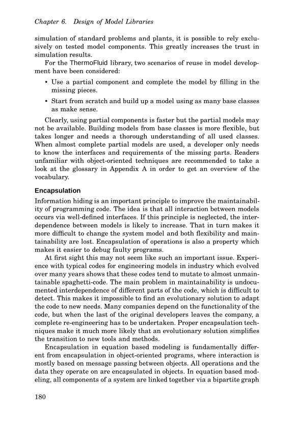
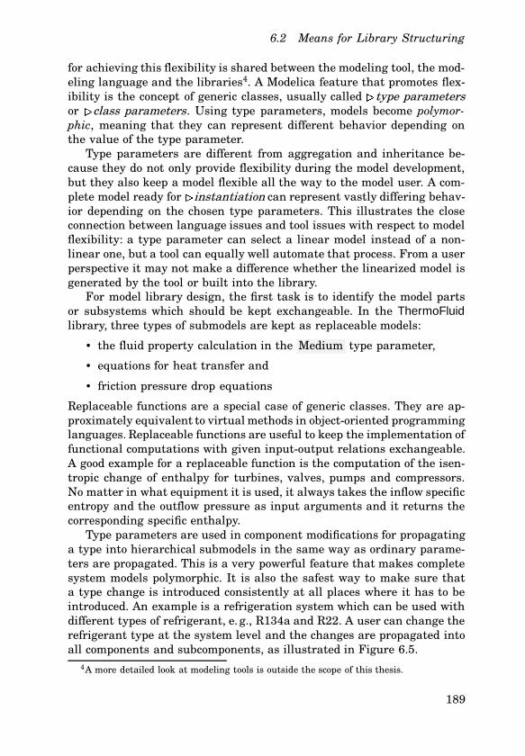
Type parameters are used in component modifications for propagatinga type into hierarchical submodels in the same way as ordinary parame-ters are propagated. This is a very powerful feature that makes completesystem models polymorphic. It is also the safest way to make sure thata type change is introduced consistently at all places where it has to beintroduced. An example is a refrigeration system which can be used withdifferent types of refrigerant, e. g., R134a and R22. A user can change therefrigerant type at the system level and the changes are propagated intoall components and subcomponents, as illustrated in Figure 6.5.
4A more detailed look at modeling tools is outside the scope of this thesis.
189
Chapter 6. Design of Model Libraries
Capillary Tube
Compressor
RefProps
RefrigerantProperties
Condenser
Eva
pora
tor
q,T
q,T
EnvironmentC
abin
et
Figure 6.5 A refrigeration system is a prototype case where type parameter prop-agation makes the model very general. The type parameter for the refrigerant typeis propagated down to all levels of the component hierarchy where a fluid propertymodel is needed.
A requirement for building such systems is that the components ortypes which are going to be redeclared have been declared as replaceableto begin with.
6.3 Design Patterns for Modeling
Software design borrowed the notion of design patterns from architecture:there it has been in use for a long time to transfer knowledge and provensolutions to new generations of architects. Design patterns in mathemati-cal modeling address recurring modeling situations by using a library de-sign or modeling language idiom that helps to solve that modeling problemefficiently. The idea is to capture a structuring concept in a catch-phrasethat is easy to remember. A design pattern should be sufficiently abstractto apply to many different situations, yet concrete enough to make itsapplication to a particular problem situation obvious. Design patterns forsoftware have been characterized into three categories: Creational Pat-terns, Structural Patterns and Behavioral Patterns. Mathematical modelshave rich dynamics, but the run-time code structure of dynamic modelsis completely static. Creational patterns are not yet implemented for thistype of engineering modeling. Some simulation environments with a focus
190
6.4 Structural Design Patterns
on discrete event systems permit to create and destroy objects with con-tinuous states during simulation runtime. Usually these are very simplemodels with few states which are integrated with their own instance ofan explicit Euler or Runge-Kutta integrators, e. g., a car on a highwaysection.
Assuming that the scope and equations of the mathematical modelsin the library are clear, the task of library design is to divide the modelsinto building blocks with well-defined interfaces, similar to Figure 6.6.Coding guidelines for structuring system models can be classified intotwo categories:
• Structural Patterns for code reuse. These can be classified asphysical patterns that abstract physical behavior and topology pat-terns reflecting system structure.
• Numerical Patterns that make sure that solution methods candeal with the models as effectively as possible.
The possibilities for design patterns are closely tied to the features ofthe modeling language. The existence of equations as independent entitiesin the language can be seen as a pattern for modeling. The flow -prefixin Modelica is a kind of design pattern, derived from a generalizationof Kirchhoff’s law for electrical circuits to all modeling domains whereflows of force, torque, mass etc. follow the same semantics. Consequently,some of the following patterns are specific to Modelica, but others arecompletely independent of the modeling language and apply equally toFORTRAN subroutines used in a legacy simulator. This holds mostly forthe numerical patterns.
6.4 Structural Design Patterns
In mathematical modeling of systems there are two structures that de-sign patterns can refer to: the inheritance based class structure and themathematical structure of the equation system. The class structure isresponsible for achieving code reuse and the mathematical structure isimportant for computational performance. Most people with experiencein mathematical modeling do not at the same time have a backgroundin software engineering. The software design motivated design patternsshould therefore be suitable for non-programmers and straightforward touse. The simplicity for the model user is not so much a question of thecomplexity of the underlying implementation but of how well the simula-tion tool wraps the concept into an intuitive user interface. Some of thefollowing simple patterns are well known since years and used by many
191
Chapter 6. Design of Model Libraries
Figure 6.6 Design patterns: Finding abstractions in a class of technical productswhich are useful jigsaw pieces in many contexts.
modelers, but usually patterns which are well known in one engineeringdomain are ignored in other domains where they are equally useful.
Unfortunately, many of the design patterns depend both on the expres-siveness of the modeling language and the capabilities of the modelingtool. The following design pattern assume Modelica 2.0 as the modelinglanguage and Dymola as the simulation tool. The patterns are extractedfrom the experiences of developing the ThermoFluid library and not meantto be complete for other engineering domains. Especially the numericalpatterns represent the most common pitfalls for non-experts in simula-tion. Our experience is that 80 % of the questions and problems arisingfrom the use of ThermoFluid would have been avoided if all users under-stood these numerical pitfalls. The remaining 20 of support requests werecaused by “chattering” of discrete modes, an as of yet unsolved problemof combined continuous and discrete simulation, see Section 2.1.
Physical Patterns
Many attempts have been made to make modeling a more systematic ac-tivity. All of these attempts emphasize the importance of identifying thedriving forces or potentials and flows. If models are split into submodelsand the connections between these submodels are abstracted to have zerovolume, then the driving forces on both sides of the connection are equaland the flows are equal in magnitude but opposite in sign. This flow se-mantics is found in all areas of physical modeling, they have among othersbeen used in Bond Graphs and the many extensions to Bond Graphs thattry to extend Bond Graphs beyond energy flow, see e. g., [Cellier, 1991]and [Gawthrop and Smith, 1995]. A recent attempt to develop systematicrules for physical modeling which can be seen as physical design patterns
192
6.4 Structural Design Patterns
is elaborated in [Weiss and Preisig, 2000].Flow semantics are not common in other thermo-hydraulic simulation
tools, but using flow semantics makes a significant difference for modelreuse. For the ThermoFluid library it simply means that a 1-to-5 flowsplitter can be realized by attaching 5 flow models to a control volumemodel. No extra model is needed and due to the flow semantics the massand energy balances are fulfilled.
DESIGN PATTERN 6.1—FLOWCONNECTOR
Use Modelica flow semantics for transport of conserved quantities for allphysical connectors between subsystems. *
EXAMPLE 2—FLOW SEMANTICS
The ThermoFluid library uses flow semantics for three flow types: vectorof component masses, flow of enthalpy and flow of momentum. The usageof flow semantics makes it in most cases unnecessary to have models forflow junctions. Splitting a flow into many smaller ones is simply done byusing a one-to-many connection.
Using flow semantics for mass and energy flows avoids errors and reducesthe number of classes needed. It also works for momentum flows for simplecases, but due to the simplification of the three-dimensional momentumvector to a scalar, connections with an angle different from 180○C haveto be modeled with a detailed model instead of just connecting the flowchannels.
Topology Patterns
DESIGN PATTERN 6.2—CONNECTORSET
Provide models with typical connector configurations as base classes. Im-plement the physics inside them in derived classes. *This design pattern is very basic and has been used in all engineeringModelica libraries, for example:
• TwoPin is a base class for electrical models such as resistors, ca-pacitances, diodes and many other models,
• TwoFlanges are base classes to all rotational, one dimensional me-chanical models with two flanges,
• TwoPorts are the base classes in ThermoFluid with two flow connec-tors like pipes, valves or pumps.
Similar base classes exist also for other libraries. These base classes arereused using single or multiple inheritance in the base classes.
193
Chapter 6. Design of Model Libraries
DESIGN PATTERN 6.3—TYPERECORD
Collect the set of variables and record-components that define type com-patibility in a record class. Classes which belong to this type compatibleset shall inherit from this class. *TypeRecord is a simple means to ensure type compatibility among a groupof models where a basic, simple model is designed to be replaceable by amore complex one if needed. The TypeRecord is used as the constrainingclass in the declaration of the replaceable component or class.
EXAMPLE 3—TYPE RECORDS
Many classes in the package CommonRecords are designed as TypeRe-cords: collections of variables that characterize a group of models. Theclass StateVariables_ph defines type compatibility for all fluid propertymodels using pressure p and specific enthalpy h as inputs to the mediumproperty calculations. The TypeRecord makes it easy for other develop-ers to write fluid property models which can replace an existing propertymodel in ThermoFluid without any adapters or interface code. TypeRecordis a fundamental pattern for polymorphic model implementations in Mod-elica.
DESIGN PATTERN 6.4—CONSISTENCYMODEL
Collect sets of data, functions and equations that have to stay togetherfor consistency reasons in one replaceable model. *This pattern is similar to class design in object-oriented programming.In mathematical modeling there are also cases where several functionsoperate on the same set of data. If these functions should be replaceable,they should by designed in such a way that it is not possible to replaceparts that render the whole model inconsistent.
EXAMPLE 4—CONSISTENT REDECLARATION
High accuracy property functions consist of a large number of parametersdescribing a non-linear thermodynamic surface. Many functions make useof this data: if e. g., a function for the speed of sound and one for the specificheat capacity are needed within the same model, the unit of redeclarationshould comprise both the functions and the parameters.
DESIGN PATTERN 6.5—PARAMETERLIFTING
This pattern ensures that consistency constraints between parameters areenforced when propagating parameters into submodels. *Geometrical parameters at the interface between two components obvi-ously have to be consistent in both models. This can be achieved with
194
6.4 Structural Design Patterns
parameters in connectors – an assertion is generated to make sure thatboth parameters are identical on both sides of the connect. However, thiswould lead to a large number of connectors. A better solution is to makethe container model responsible for consistency of the parameters. This isbest demonstrated with an example.
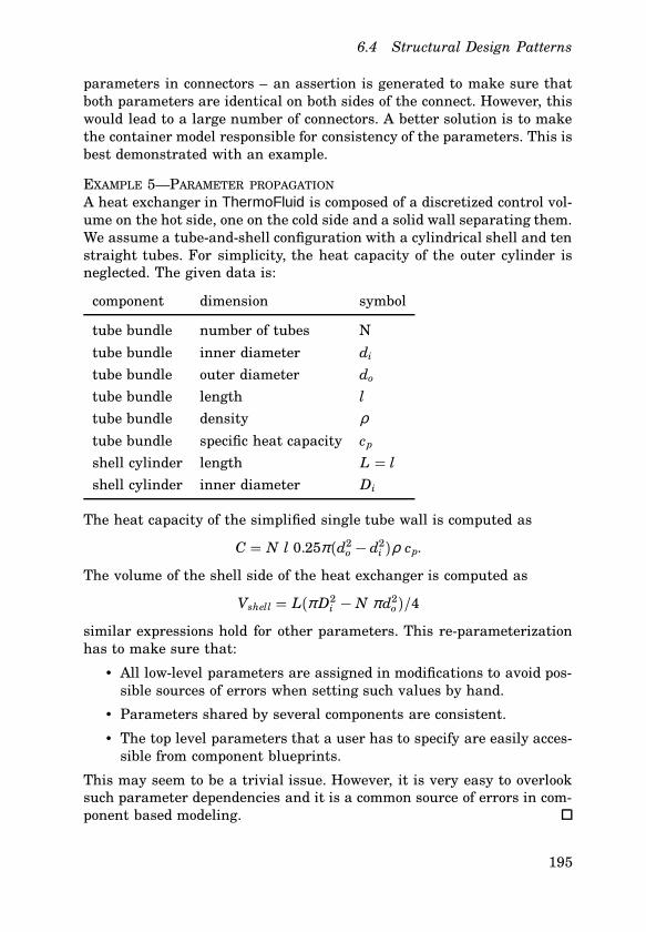
EXAMPLE 5—PARAMETER PROPAGATION
A heat exchanger in ThermoFluid is composed of a discretized control vol-ume on the hot side, one on the cold side and a solid wall separating them.We assume a tube-and-shell configuration with a cylindrical shell and tenstraight tubes. For simplicity, the heat capacity of the outer cylinder isneglected. The given data is:
component dimension symbol
tube bundle number of tubes Ntube bundle inner diameter di
tube bundle outer diameter do
tube bundle length ltube bundle density ρtube bundle specific heat capacity cp
shell cylinder length L = lshell cylinder inner diameter Di
The heat capacity of the simplified single tube wall is computed as
C = N l 0.25π (d2o − d2
i )ρ cp.
The volume of the shell side of the heat exchanger is computed as
Vshell = L(π D2i − N π d2
o)/4
similar expressions hold for other parameters. This re-parameterizationhas to make sure that:
• All low-level parameters are assigned in modifications to avoid pos-sible sources of errors when setting such values by hand.
• Parameters shared by several components are consistent.
• The top level parameters that a user has to specify are easily acces-sible from component blueprints.
This may seem to be a trivial issue. However, it is very easy to overlooksuch parameter dependencies and it is a common source of errors in com-ponent based modeling.
195
Chapter 6. Design of Model Libraries
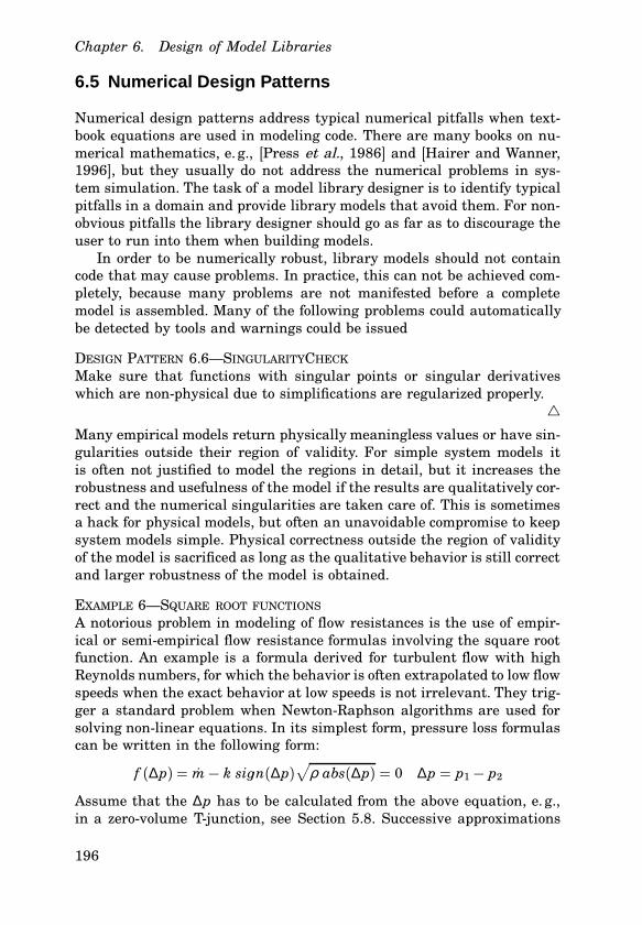
6.5 Numerical Design Patterns
Numerical design patterns address typical numerical pitfalls when text-book equations are used in modeling code. There are many books on nu-merical mathematics, e. g., [Press et al., 1986] and [Hairer and Wanner,1996], but they usually do not address the numerical problems in sys-tem simulation. The task of a model library designer is to identify typicalpitfalls in a domain and provide library models that avoid them. For non-obvious pitfalls the library designer should go as far as to discourage theuser to run into them when building models.
In order to be numerically robust, library models should not containcode that may cause problems. In practice, this can not be achieved com-pletely, because many problems are not manifested before a completemodel is assembled. Many of the following problems could automaticallybe detected by tools and warnings could be issued
DESIGN PATTERN 6.6—SINGULARITYCHECK
Make sure that functions with singular points or singular derivativeswhich are non-physical due to simplifications are regularized properly.
*Many empirical models return physically meaningless values or have sin-gularities outside their region of validity. For simple system models itis often not justified to model the regions in detail, but it increases therobustness and usefulness of the model if the results are qualitatively cor-rect and the numerical singularities are taken care of. This is sometimesa hack for physical models, but often an unavoidable compromise to keepsystem models simple. Physical correctness outside the region of validityof the model is sacrificed as long as the qualitative behavior is still correctand larger robustness of the model is obtained.
EXAMPLE 6—SQUARE ROOT FUNCTIONS
A notorious problem in modeling of flow resistances is the use of empir-ical or semi-empirical flow resistance formulas involving the square rootfunction. An example is a formula derived for turbulent flow with highReynolds numbers, for which the behavior is often extrapolated to low flowspeeds when the exact behavior at low speeds is not irrelevant. They trig-ger a standard problem when Newton-Raphson algorithms are used forsolving non-linear equations. In its simplest form, pressure loss formulascan be written in the following form:
f (∆p) = m− k sinn(∆p)√
ρ abs(∆p) = 0 ∆p = p1 − p2
Assume that the ∆p has to be calculated from the above equation, e. g.,in a zero-volume T-junction, see Section 5.8. Successive approximations
196
6.5 Numerical Design Patterns
to the solution of f (∆p) are obtained from the following iteration:
∆p j+1 = ∆p j + f (∆p j)V f (∆p j )V∆p j
� ∆p j + f (∆p j)∆ f (∆p j )∆(∆p j )
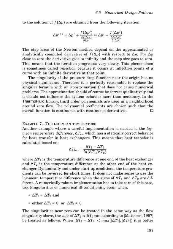
The step sizes of the Newton method depend on the approximated oranalytically computed derivative of f (∆p) with respect to ∆p. For ∆pclose to zero the derivative goes to infinity and the step size goes to zero.This means that the iteration progresses very slowly. This phenomenonis sometimes called inflection because it occurs at inflection points of acurve with an infinite derivative at that point.
The singularity of the pressure drop function near the origin has nophysical significance. Therefore it is perfectly reasonable to replace thesingular formula with an approximation that does not cause numericalproblems. The approximation should of course be correct qualitatively andit should not influence the system behavior more than necessary. In theThermoFluid library, third order polynomials are used in a neighborhoodaround zero flow. The polynomial coefficients are chosen such that theoverall function is continuous with continuous derivatives.
EXAMPLE 7—THE LOG-MEAN TEMPERATURE
Another example where a careful implementation is needed is the log-mean temperature difference, ∆Tlm which has a statically correct behaviorfor heat transfer in heat exchangers. This means that heat transfer iscalculated based on:
∆Tlm =∆T1 − ∆T2
ln(∆T1/∆T2)where ∆T1 is the temperature difference at one end of the heat exchangerand ∆T2 is the temperature difference at the other end of the heat ex-changer. Dynamically and under start-up conditions, the temperature gra-dients can be reversed for short times. It does not make sense to use thelog-mean temperature difference when the signs of ∆T1 and ∆T2 are dif-ferent. A numerically robust implementation has to take care of this case,too. Singularities or numerical ill-conditioning occur when:
• ∆T1 � ∆T2 and
• either ∆T1 � 0 or ∆T2 � 0.
The singularities near zero can be treated in the same way as the flowsingularity above, the case of ∆T1 � ∆T2 can according to [Mattsson, 1997]be treated as follows. When h∆T1 − ∆T2h < max(h∆T1h, h∆T2h) it is better
197
Chapter 6. Design of Model Libraries
to use the Taylor expansion
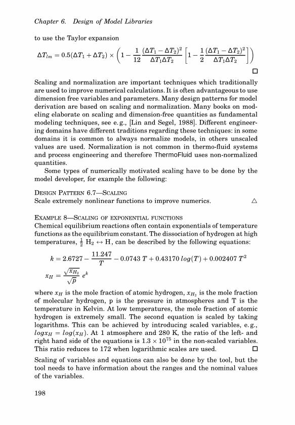
∆Tlm = 0.5(∆T1 + ∆T2) �(
1− 112(∆T1 − ∆T2)2
∆T1∆T2
[1− 1
2(∆T1 − ∆T2)2
∆T1∆T2
])
Scaling and normalization are important techniques which traditionallyare used to improve numerical calculations. It is often advantageous to usedimension free variables and parameters. Many design patterns for modelderivation are based on scaling and normalization. Many books on mod-eling elaborate on scaling and dimension-free quantities as fundamentalmodeling techniques, see e. g., [Lin and Segel, 1988]. Different engineer-ing domains have different traditions regarding these techniques: in somedomains it is common to always normalize models, in others unscaledvalues are used. Normalization is not common in thermo-fluid systemsand process engineering and therefore ThermoFluid uses non-normalizedquantities.
Some types of numerically motivated scaling have to be done by themodel developer, for example the following:
DESIGN PATTERN 6.7—SCALING
Scale extremely nonlinear functions to improve numerics. *
EXAMPLE 8—SCALING OF EXPONENTIAL FUNCTIONS
Chemical equilibrium reactions often contain exponentials of temperaturefunctions as the equilibrium constant. The dissociation of hydrogen at hightemperatures, 1
2 H2 1 H, can be described by the following equations:
k = 2.6727− 11.247T
− 0.0743 T + 0.43170 lon(T)+ 0.002407 T2
xH =√xH2√
pek
where xH is the mole fraction of atomic hydrogen, xH2 is the mole fractionof molecular hydrogen, p is the pressure in atmospheres and T is thetemperature in Kelvin. At low temperatures, the mole fraction of atomichydrogen is extremely small. The second equation is scaled by takinglogarithms. This can be achieved by introducing scaled variables, e. g.,lonxH = lon(xH). At 1 atmosphere and 280 K, the ratio of the left- andright hand side of the equations is 1.3� 1075 in the non-scaled variables.This ratio reduces to 172 when logarithmic scales are used.
Scaling of variables and equations can also be done by the tool, but thetool needs to have information about the ranges and the nominal valuesof the variables.
198
6.5 Numerical Design Patterns
DESIGN PATTERN 6.8—VARIABLERANGES
Set tight minimum and maximum and accurate nominal values for allphysical variables. *Accurate minimum, maximum and nominal values can help numericalroutines to find the solution and improve the numerical conditioning.Making sure that ranges are set as accurately as possible is thus a partof careful modeling. Many models have mathematically correct solutionswhich are physically meaningless. Equations for chemical equilibrium al-ways permit solutions with negative concentrations which do not makesense physically. Limiting the search for solutions of nonlinear solvers tothe physically meaningful ranges reduces the number of failures and theneed for users to provide good initial guess values.
Nominal values are for example important to determine how pertur-bations should be chosen for numerical linearization of a model.
DESIGN PATTERN 6.9—SMOOTHING
Piece-wise and discontinuous function approximations which should becontinuous for physical reasons shall be smoothened. *In physical modeling it is common to have empirical or semi-empiricalformulae that approximate measured data. Non-dimensional numbers areused to describe a given problem with a few parameters. In fluid flowthere are many relations for turbulent or laminar flow with considerableuncertainty in the transition.
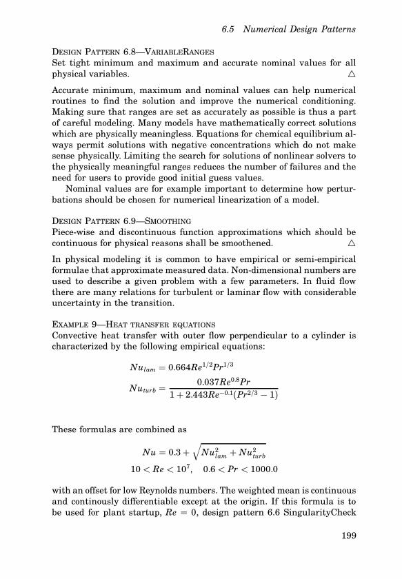
EXAMPLE 9—HEAT TRANSFER EQUATIONS
Convective heat transfer with outer flow perpendicular to a cylinder ischaracterized by the following empirical equations:
Nulam = 0.664Re1/2Pr1/3
Nuturb =0.037Re0.8Pr
1+ 2.443Re−0.1(Pr2/3 − 1)
These formulas are combined as
Nu = 0.3+√
Nu2lam + Nu2
turb
10 < Re < 107, 0.6 < Pr < 1000.0
with an offset for low Reynolds numbers. The weighted mean is continuousand continously differentiable except at the origin. If this formula is tobe used for plant startup, Re = 0, design pattern 6.6 SingularityCheck
199
Chapter 6. Design of Model Libraries
should be used to make the formula robust at zero flow speed. Note thatin this case smoothing acts like a weighted summation because the totalNusselt number is always larger than any of the parts.
The following two design patterns deal with the stiffness of the resultingequation system, see Chapter 2. Stiffness is often the result of composinga system from subsystems. Therefore it is not possible to avoid all stiffnessproblems with library models. Choosing a solver that can deal with stiffequations may not necessarily be the best solution. Making the equationnon-stiff speeds up the solution considerably and broadens the range ofapplicable solvers.
DESIGN PATTERN 6.10—TIMECONSTANTSELECTIONMake a problem non-stiff by using a steady-state assumption (singularperturbation technique) when the fast dynamics of the system are not ofinterest. Make a problem non-stiff by approximating very slow dynamicswith constants. *Typical examples of this technique are given in Chapter 4, the assump-tion of chemical equilibrium for fast reactions in Section 4.9 and usingthe quasi steady-state assumption for the momentum balance of fluidsin Section 4.3. The assumption of taking the volume of a control volumeto the limit of zero, used in Section 5.8 for T-junctions, is based on thesame considerations. This example demonstrates that the decision to usea control volume model with or without dynamics has to be done on thesystem level by the model user. A related technique is to replace very slowdynamics like fouling with a constant. Modelers should be aware of thefact that it only makes sense to look at a limited range of system timeconstants at a time. This is reflected in the name to this design pattern.
DESIGN PATTERN 6.11—EASINGSTIFFNESSRender a problem less stiff by making the time constants of the fast dy-namics slower. *This design pattern has been used for modeling of turbines in powerplants, see [Thumm, 1989]. This particular way of dealing with stiffness isbetter than removing the fast states is explained in Section 5.8. The dis-advantage of a singular value perturbation in the steam turbine exampleis a non-linear equation system involving all tap-off mass flows and pres-sures in the turbine. This is a purely numerical motivation for knowinglyaltering the dynamics of the real system. Under certain circumstances,this is a reasonable solution:
• Removing the fast states by a singular perturbation leads to numer-ical difficulties, typically non-linear equations which can be difficultto solve, especially at initialization time.
200
6.5 Numerical Design Patterns
• The dynamics after changing the time constants are still much fasterthan the dynamics of interest.
• The change of the time constants makes the equation system solv-able by solvers for stiff differential equations.
This technique can also be used to decrease model stiffness in order touse explicit solvers for hardware-in-the-loop simulation. In the case of thesteam turbine discussed in Section 4.7, the ratio of the largest to smallesteigenvalue was changed from 106 to 100 without a noticeable influenceon the dynamics of interest. From a control perspective this means thatthe model is rendered numerically tractable by changing it outside thefrequency range of interest.
The design patterns EasingStiffness and TimeConstantSelection areaddressing the same problem but suggesting different solutions. Thisshows that experience is needed to choose the best solution. In manycases both of the above methods will work well with similar performance,in other cases one of the methods is clearly superior to the other.
DESIGN PATTERN 6.12—FULLYSYMBOLICCODE
Make sure that symbolic derivatives are available for all model parts, in-cluding external functions. This improves the solution of non-linear equa-tion systems and enables automatic index reduction. *This design pattern is specific to tools which support symbolic manipu-lation of the model code like automatic index reduction and automaticdifferentiation, but require that all model equations and functions aredifferentiable. This is the case in Dymola, MathModelica, ABACUSS IIand to some extent gPROMS. High index problems, compare Section 2.1,arise when algebraic equations constrain states to a manifold defined byan algebraic equation. Object-oriented model composition goes hand-in-hand with the need for automatic index reduction, because the constraintequations are the equations generated from a connect statement. An algo-rithmic way to reformulate the model to an equivalent problem with indexone is based on the symbolic differentiation of the algebraic equation. Dueto the complexity of object-oriented modeling, a large part of the algebraicequations or functions of a model can become a constraint. Consequently,modelers should provide derivatives for all model functions. In Modelica,this is done with the help of derivative annotations. Compared to usingequations, this is additional work for the modeler. However, it can not beavoided for external functions or when functions have other significantadvantages over equations.
DESIGN PATTERN 6.13—DISCONTINUITIES
Avoid discontinuities in user defined functions whenever possible. *
201
Chapter 6. Design of Model Libraries
A Modelica compiler can easily detect discontinuities in equations, but thisis not the case with functions. A function returning discontinuous outputsfor continuous inputs will cause serious trouble for numerical integrators.Instead of a function with one discontinuity, two functions should be pro-vided. An event is generated automatically when the functions are calledin the branches of an if-expression.
It may be impossible to avoid discontinuities when reusing externalfunctions. The next design pattern applies to external functions with dis-continuities or discontinuous derivatives.
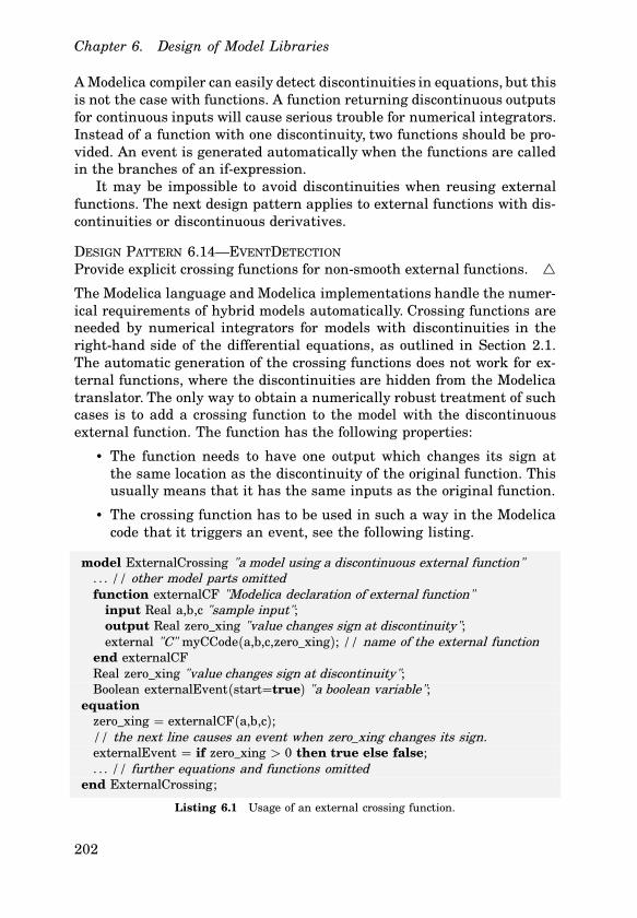
DESIGN PATTERN 6.14—EVENTDETECTION
Provide explicit crossing functions for non-smooth external functions. *The Modelica language and Modelica implementations handle the numer-ical requirements of hybrid models automatically. Crossing functions areneeded by numerical integrators for models with discontinuities in theright-hand side of the differential equations, as outlined in Section 2.1.The automatic generation of the crossing functions does not work for ex-ternal functions, where the discontinuities are hidden from the Modelicatranslator. The only way to obtain a numerically robust treatment of suchcases is to add a crossing function to the model with the discontinuousexternal function. The function has the following properties:
• The function needs to have one output which changes its sign atthe same location as the discontinuity of the original function. Thisusually means that it has the same inputs as the original function.
• The crossing function has to be used in such a way in the Modelicacode that it triggers an event, see the following listing.
model ExternalCrossing "a model using a discontinuous external function". . . // other model parts omittedfunction externalCF "Modelica declaration of external function"
input Real a,b,c "sample input";output Real zero_xing "value changes sign at discontinuity";external "C" myCCode(a,b,c,zero_xing); // name of the external function
end externalCFReal zero_xing "value changes sign at discontinuity";Boolean externalEvent(start=true) "a boolean variable";
equationzero_xing = externalCF(a,b,c);// the next line causes an event when zero_xing changes its sign.externalEvent = if zero_xing > 0 then true else false;. . . // further equations and functions omitted
end ExternalCrossing;
Listing 6.1 Usage of an external crossing function.
202
6.6 Conclusions
This type of problem is typical for interfacing Modelica to traditional C– orFORTRAN codes. A non-trivial example which required to develop the ex-ternal crossing function and the Modelica interface for multi-phase prop-erty calculations is described in [Tummescheit and Eborn, 2002]. Cross-ing functions for external functions could be avoided with similar tech-niques as derivatives for external functions. Automatic differentiationtechniques, described in more detail in Chapter 7, can not only analyzecode to compute the derivatives of that code, they can also be used to de-tect discontinuities. This has been demonstrated in [Tolsma and Barton,2002].
6.6 Conclusions
This chapter discussed two issues in development of object-oriented modellibraries which are independent of the application domain: code structur-ing for reuse and numerics. Both issues are important to obtain a flexibleand robust library. The numerical design patterns and examples in thischapter are proposals for avoiding difficulties but they do not cover allproblems that users of ThermoFluid have experienced. The structural de-sign patterns are also only a few patterns for structuring the model code,but they summarize patterns that were successfully used in ThermoFluid.Experiences from model libraries in other domains indicate that there aremany similarities between different domains.
Object-oriented modeling or software techniques are not like a silverbullet that ensures well structured, well documented and flexible code.Discipline in documenting code and adequate use of the object-orientedfeatures are necessary in order to take full advantage of the benefits ofobject orientation.
203