Embed Size (px)
Citation preview
DESIGN OF LINING FOR DELIVERY TUNNELS
IN CREEPING HARD ROCKS
V. L. Kubetskii and V. S. F, ristov UDC 624.191.1 : 624.131.25.001.5
It is a well-known fact that the economic design of linings for hydraulic delivery tunnels calls for maximum utilization of the load-carrying capacity of the enclosing hard rocks. In present design practice, such rocks are taken to be elastic, instantaneously deformed media, and stresses in the lining are determined by the theory of elasticity. At the same time, investigations of deformation properties of hard rocks in situ show that most of such rocks, under continuous load, are capable of different degrees of continued deformation, i.e., of creep. For this reason, the act- ual state of stress in the lining may substantially differ from that computed from the theory of elasticity.
This article integrates the results of special fietd studies of creep in hard rocks at the V. V. Kuibyshev MISI (Moscow Civil Engineering Institute) * and presents a method of stress state calculation for delivery tunnels in creep- prone rocks.
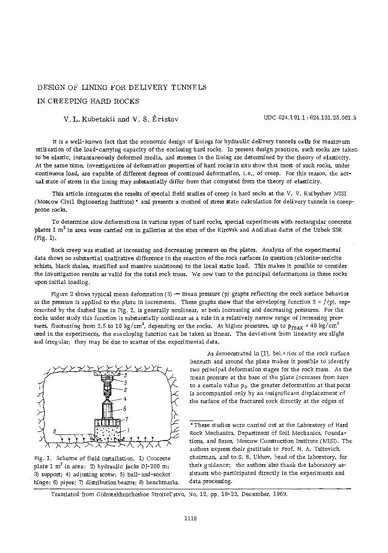
To determine slow deformations in various types of hard rocks, special experiments with rectangular concrete plates 1 m z in area were carried out in galleries at the sites of the Kirovsk and Andizhan dams of the Uzbek SSR (Fig. 1).
Rock creep was studied at increasing and decreasing pressures on the plates. Analysis of the experimental data shows no substantial qualitative difference in the reaction of the rock surfaces in question (chlorite-sericite schists, black shales, stratified and massive sandstones) to the local static load. This makes it possible to consider the investigation results as valid for the total rock mass. We now turn to the principal deformations in these rocks upon init ial loading.
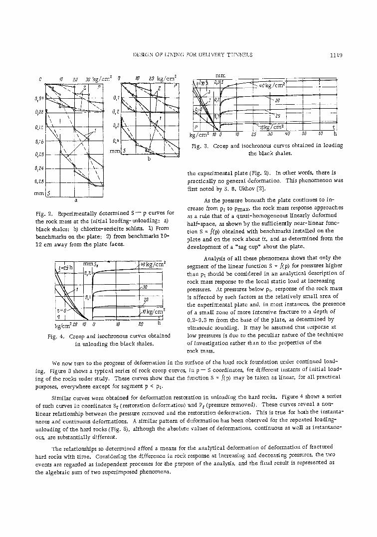
Figure 2 shows typical mean deformation (S) - - mean pressure (p) graphs reflecting the rock surface behavior as the pressure is applied to the plate in increments. These graphs show that the enveloping function S = f(p), rep- resented by the dashed line in Fig. 2, is generally nonlinear, at both increasing and decreasing pressures. For the rocks under study this function is substantially nonlinear as a rule in a relatively narrow range of increasing pres- sures, fluctuating from 2.5 to 10 kg/cm 2, depending on the rocks. At higher pressures, up to Pmax = 40 kg/cm z used in the experiments, the enveloping function can be taken as linear. The deviations from linearity are slight and irregular; they may be due to scatter of the experimental data.
Y
Y
~..~ ~ ' -
~---- g -C
..16 ~.
$7
Fig. 1. Scheme of field installation. 1) Concrete plate 1 m z in area; 2) hydraulic jacks DJ-200 m; 3) support; 4) adjusting screw; 5) ball-and-socket hinge; 6) pipes; 7) distribution beams; 8) benchmarks.
As demonstrated in [1], bet.~ dot of the rock surface beneath and around the plate makes it possible to identify two principal deformation stages for the rock mass. As the mean pressure at the base of the plate increases from zero to a certain value Pt, the greater deformation at that point is accompanied only by an insignificant displacement of the surface of the fractured rock directly at the edges of
*These studies were carried out at the Laboratory of Hard
Rock Mechanics, Department of Soil Mechanics, Founda-
tions, and Bases, Moscow Construction Institute (MISI). The
authors express their gratitude to Prof. N. A. Tsitovich,
chairman, and to S. B. Ukhov, head of the laboratory, for
their guidance; the authors also thank the laboratory as-
sistants who participated directly in the experiments and data processing.
Translated from Gidrotekhnicheskoe Stroitel'stvo, No. 12, pp. 16-23, December, 1969.
1118
DESIGN OF LINING FOR DELIVERY TUNNELS 1119
0,04
o, oo
a,~z
0,16
O ZO
07Z~
O, Z8
mm
iO
l\\\ '\\
\ / x \ k X, /
k
a
Zg 30 k g / c m 2 0 10 20 k g / c m 2
0,I " "~
x O, Z ~ - ,
k I 073 \ ~
m m 5 h ~ _
b
Fig. 2. tNperimental ly de termined S - p curves for
the rock mass at the in i t i a l loading-unloading: a) black shales; b) ch lor i t e - se r ic i t e schists. 1) From benchmarks on the plate; 2) from benchmarks 10-
12 cm away from the pla te faces.
mini:/_ \
0,1 f ~
k. kg/cm 2zo rO O
Fig. 4.
q0kg/cm
,30
gO /
/ 0 kg /cm [A
I0 z0 h
Creep and isochronous curves obtained
in unloading the b lack shales.
ing.
mm
k g / c m 2 SO 0 10 z0 ~0 qa 50 ~0 h
Fig. 3. Creep and isochronous curves obtained in loading
the b lack shales.
the exper imenta l plate (Fig. 2). In other words, there is
prac t ica l ly no general deformation. This phenomenon was
first noted by S. B. Ukhov [2].
As the pressure beneath the plate continues to in-
crease from Pl to Pmax, the rock mass response approaches as a rule that of a quasi-homogeneous l inearly deformed
half -space, as shown by the suff icient ly near - l inear func- t ion S = f(p) obtained with benchmarks installed on the p la te and on the rock about it, and as determined from the
deve lopment of a "sag cup" about the plate.
Analysis of al l these phenomena shows that only the
segment of the l inear function S = f(p) for pressures higher than Pl should be considered in an analyt ica l descript ion of
rock mass response to the local s tat ic load at increasing pressures. At pressures below Pt, response of the rock mass
is affected by such factors as the reIa t ively smaU area of the exper imenta l plate and, in most instances, the presence of a smal l zone of more intensive fracture to a depth of 0 .2-0.3 m from the base of the plate, as determined by ultrasonic sounding. It may be assumed that response at
low pressures is due to the pecul iar nature of the technique of invest igat ion rather than to the properties of the
rock mass.
We now turn to the progress of deformation in the surface of the hard rock foundation under continued load- Figure 3 shows a typ ica l series of rock creep curves, in p - - S coordinates, for different instants of in i t ia l load-
ing of the rocks under study. These curves show that the function S = f(p) may be taken as linear, for a l l p rac t ica l
purposes, everywhere except for segment p < Pl.
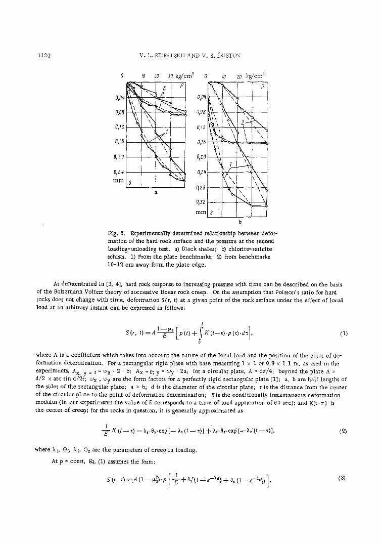
Similar curves were obtained for deformat ion restoration in unloading the hard rocks. Figure 4 shows a series
of such curves in coordinates Sr (restoration deformation) ~nd Pr (pressure removed). These curves revea l a non-
l inear relationship between the pressure removed and the restoration deformation. This is t rue for both the instanta-
neous and continuous deformations. A similar pattern of deformat ion has been observed for the repeated loading- unloading of the hard rocks (Fig. 5), although the absolute values of deformations, continuous as well as instantane-
ous, are substantially different.
The relationships so determined afford a means for the analyt icaI deformation of deformat ion of fractured
hard rocks with t ime. Considering the dif ference in rock response at increasing and decreasing pressures, the two events are regarded as independent processes for the pnrpose of the analysis, and the finaI result is represented as
the algebraic sum of two superimposed phenomena.
1120 V. L. KUBETSKII AND V. S. ~RISTOV
O, Oq
0,08
0,I,~
o,~6
0, 7.0
O, Zq-
m m
10
\ , k
5
ZO 30 kg/cm 2
p
013Z m m
I0 ZO kg/cm2
i
---...5
s [ [ b
Fig. 5. I~per imenta l ly determined relationship between defor-
mat ion of the hard rock surface and the pressure at the second
loading-unloading test. a) Black shales; b) ch lor i t e - se r ic i t e
schists. 1) From the plate benchmarks; 2) from benchmarks 10-12 cm away from the plate edge.
As demonstrated in [3, 4], hard rock response to increasing pressure with t ime can be descr ibed on the basis
of the Boltzmann Volterr theory of successive l inear rock creep. On the assumption that Poisson's ratio for hard rocks does not change with t ime, deformat ion S(r, t) at a g iven point of the rock surface under the effect of local load at an arbitrary instant can be expressed as follows:
t
S(r, t)~A ~ - ~ [p(t) + ~ K (t--~).p (~).d~], o
( I )
where A is a coef f ic ien t which takes into account t he nature of the loca l load and the posit ion of the point of de-
formation determinat ion. For a rectangular rigid plate with base measuring 1 x 1 or 0.9 x 1.1 m, as used in the
d/2experiments'x arc sin d/AxB y = 0 = co x �9 2 �9 b; Ax = 0; y = coy �9 2a; for a c ircular plate, A = dTr/4; beyond the plate A = cox , coy are the form factors for a perfect ly rigid rectangular plate [1]; a, b are half lengths of
the sides of the rectangular pla te ; a > b; d is the d iamete r of the circular plate; r is the d is tance from the center
of the circular plate to the point of deformation de terminat ion; Eis the condi t ional ly instantaneous deformation modulus (in our experiments the va lue of g corresponds to a t i m e of load appl ica t ion of 60 sec); and K ( t - r ) Ls the center of creep; for the rocks in question, it is general ly approximated as
1 -E - K (t - - ~) = ;kt. 0,. exp [ - - ;q (t - - =)l + ~,=" 0=-exp [ - - ;%' (t - - =)], (2)
where k s, ~i, X2, @z are the parameters of creep in loading.
At p = const, Eq. (1) assumes the form:
0 = 4 (1 = + (1 - r----E1 + 0,,(, (3)
DESIGN OF LINING FOR DELIVERY TU NNELS 1121
0,075 2
I ~ I . . . . . 2 0 - 3 0 "
0 , 0 5 0 ~ - - - - - @ - x . . . . 30-40 - t t I
t ....... ! t 0
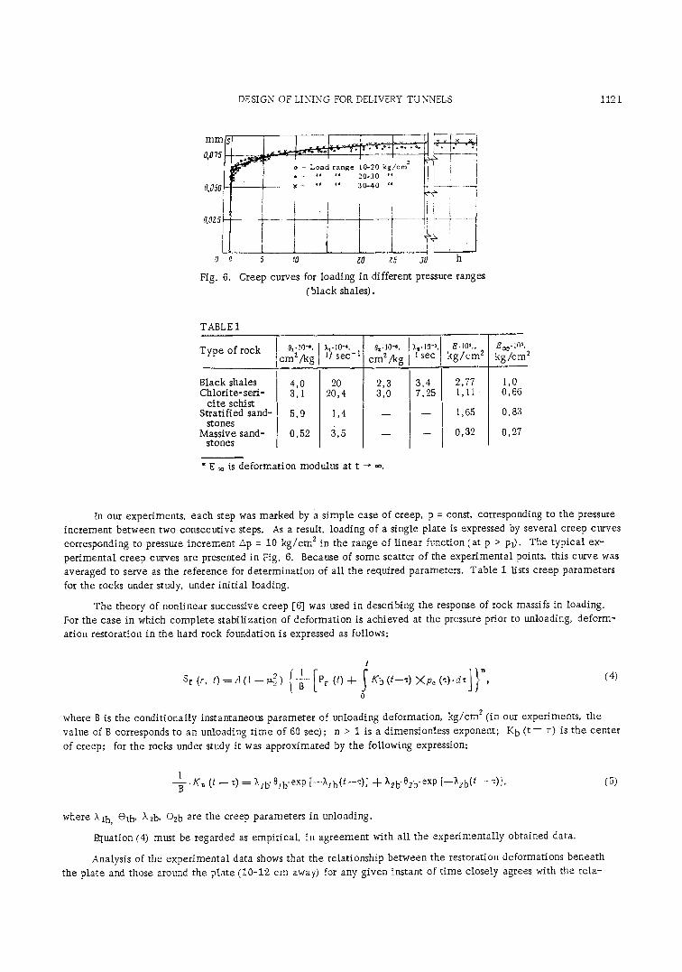
Fig. 6.
5 tO ZO t5 ,1o h
Creep curves for loading in different pressure ranges (black shales).
TABL g I
Type of rock (~l" 10-s, cma/kg
),t.lO-t I I s e c ' l
Or- I0"~,
cm2/kg
Black shales I 4,0 20 Chlorite-seN- I 3,1 20,4
ci te schist ] Stratified sand- I 5,9 1,4
stones I Massive sand- �9 0,52 3,5
stones
�9 E ~o is deformation modulus at t --" .0.
2,3 3,0
ks- 10% 1 s e c
3, 5 7,
E.lOS,, k g / c m 2
2,77 1,11
1,65
0,32
Ec~-105, kg /cm 2
1,0 0,66
0,83
0,27
In our experiments, each step was marked by a s imp le case of creep, p = const, corresponding to the pressure increment between two consecutive steps. As a result, loading of a single pIate is expressed by several creep curves corresponding to pressure increment ZXp = 10 k g / c m 2 in the range of l inear function (at p > Pt). The typica l ex- per imenta l creep curves are presented in Fig. 6. Because of some scatter of the experimental points, this curve was averaged to serve as the reference for determinat ion of all the required parameters. Table 1 lists creep parameters
for the rocks under study, under in i t ia l loading.
The theory of nonl inear successive creep [6] was used in describing the response of rock massifs in loading. For the case in which comple te s tabi l izat ion of deformation is achieved at the pressure prior to unloading, deform- ation restoration in the hard rock foundation is expressed as follows:
t
Sr (r, t ) = A ( 1 - - ~ 5 ) I B Pr (t)-{- K b ( t - - = ) ; K p e ( , ) ' d z ] ", 0
where B is the condi t ional ly instantaneous parameter of unloading deformation, kg /cm z (in our experiments, the value of B corresponds to an unloading t ime of 60 see); n > 1 is a dimensionless exponent; K b ( t - - r) is the center of creep; for the rocks under study it was approximated by the following expression:
l -~- 'KB (t - - ~) = Xsb. 0sb.exp [--7,sb(t--~)] -}- h2b. 0zb. exp [--Tt2b(t-- ~)], (5)
where Xlb, @lb, X2b, 02b are the creep parameters in unloading.
Rtuation (4) must be regarded as empirical, in agreement with al l the exper imental ly obtained data.
Analysis of the exper imenta l data shows that the relationship between the restoration deformations beneath the plate and those around the plate (10-12 cm away) for any given instant of t ime closely agrees with the re la-
1122 V.L. KUBETSKII ANDV. S. ERISTOV
" - - i : t=fh--
= z ~ h
~ ---b i t ~ i L,Pe l i i " Z
--it -:3 --5t -8
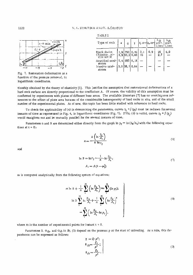
Fig. 7. Restoration deformation as a function of the pressure removed, in logarithmic coordinates.
tionship obtained by the theory of elasticity [1].
TABLE 2
Type of rock n Q l zvlo-, Z,.lO-, xlo-,. • -~, I / sec 1/sec
Black sha[es Chlorit e-. 2ri cite schist
Stratified sand- stones
Massive sand- stones
750 0,46 3,1 1,g 62,2 0,66 23 2,9
2,4 685 0,18 - -
3,0 38, 1 0,64 - -
0,9 25 2,7
6,0
This justifies the assumption that restorational deformations of a hard rock surface are direct ly proportional to the coefficient A. Of course, the validi ty of this assumption must be confirmed by experiments with plates of different base areas. The available literature [7] has no unambiguous ref- erences to the effect of plate area because of the considerable heterogeneity of hard rocks in sitv~ and of the small number of the experimental plates. As of now, this topic has been l i t t le studied with reference to hard rocks.
To check the appl icabi l i ty of (4) in determining the parameters, curves S r = f (Pr) must be redrawn for several instants of t ime as represented in Fig. 4, in logarithmic coordinates (Fig. 7). If Eq. (4) is val id , curves S r = f (pr) would straighten out and be mutually parallel for the several instants of t ime.
Parameters n and B are determined either directly from the graph In P r - - In (Sr/A 1) with the following equa- t'ions at t = 0):
n ~ lnp r
and
In B = l n r - - - - ~ - ' l n A I '
A, = A (I --~)
(7)
or is computed analyt ical ly from the following system of equations:
m t n
SB m In B -b T In ~ (In Pr);
I 1 t t l t n
S , 1 { SB \ ' b i b E in "~-1 -I--'h-- E k ln'-~-~ )
1 1 m
I
where m is the number of experimental points for instant t = 0.
Parameters B, @tb, and @2b in Rt. (5) depend on the pressure p at the start of unloading. pendence can be expressed as follows:
B = Q . p ~ ; z1 ,
z2 02b= p---y- �9
( 8 )
As a rule, this de-
( 9 )
DESIGN OF LINING FOR DELIVERY TUNNELS 1123
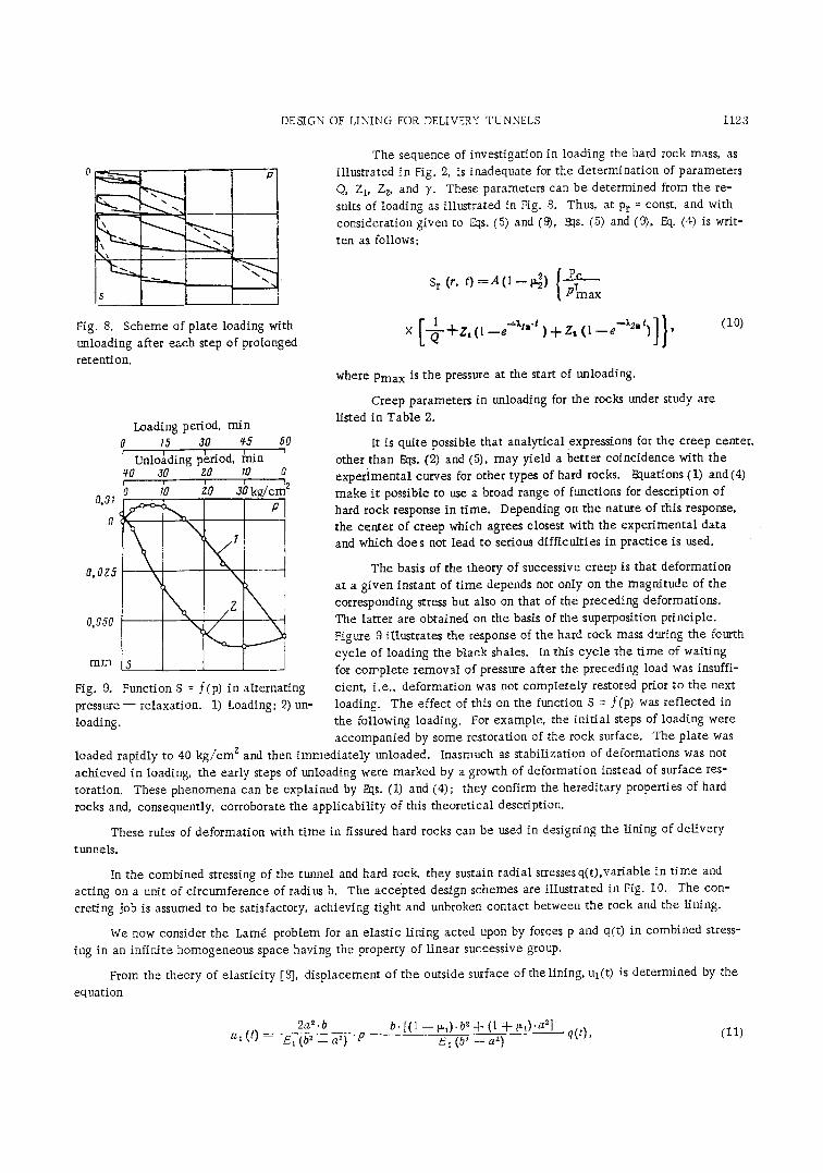
Fig. 8. Scheme of plate loading with unloading after each step of prolonged retention.
Loading period, min 0 h~ 30 q5 60
Unloading penod, ~nin qO 30 28 tO 0
12 'o lb in abl /cm 0.01
0,015
\ \ / Z
mm S
Fig. 9. Function S = f (p) in alternating pressure-- relaxation. 1) Loading; 2) un- loading.
The sequence of investigation in loading the hard rock mass, as illustrated in Fig. 2, is inadequate for the determination of parameters Q, Z I, Z 2, and y. These parameters can be determined from the re- suits of loading as illustrated in Fig. 8. Thus, at Pr = const, and with consideration given to Us. (5) and (9), Rts. (5) and (9), 7xt. (4) is writ-
ten as follows:
Pc Sr (', 0 = A ( I - - ~ ) P~max
(1o)
where Pmax is the pressure at the start of unloading.
Creep parameters in unloading for the rocks under study are
listed in Table 2.
It is quite possible that analytical expressions for the creep center, other than Eqs. (2) and (5), may yield a better coincidence with the experimental curves for other types of hard rocks. Equations (1) and(4) make it possible to use a broad range of functions for description of hard rock response in time. Depending on the nature of this response, the center of creep which agrees closest with the experimental data and which does not lead to serious difficulties in practice is used.
The basis of the theory of successive creep is that deformation at a given instant of time depends not only on the magnitude of the corresponding stress but also on that of the preceding deformations. The latter are obtained on the basis of the superposition principle. Figure 9 illustrates the response of the hard rock mass during the fourth cycle of loading the black shales. In this cycle the time of waiting for complete removal of pressure after the preceding load was insuffi- cient, i.e., deformation was not completely restored prior to the next loading. The effect of this on the function S = f(p) was reflected in the following loading. For example, the ini t ial steps of loading were accompanied by some restoration of the rock surface. The plate was
loaded rapidly to 40 kg/cm z and then immediately unloaded. Inasmuch as stabilization of deformations was not achieved in loading, the early steps of unloading were marked by a growth of deformation instead of surface res- toration. These phenomena can be explained by Eqs. (1) and (4); they confirm the hereditary properties of hard
rocks and, consequently, corroborate the applicability of this theoretical description.
These rules of deformation with t ime in fissured hard rocks can be used in designing the lining of delivery
tunnels.
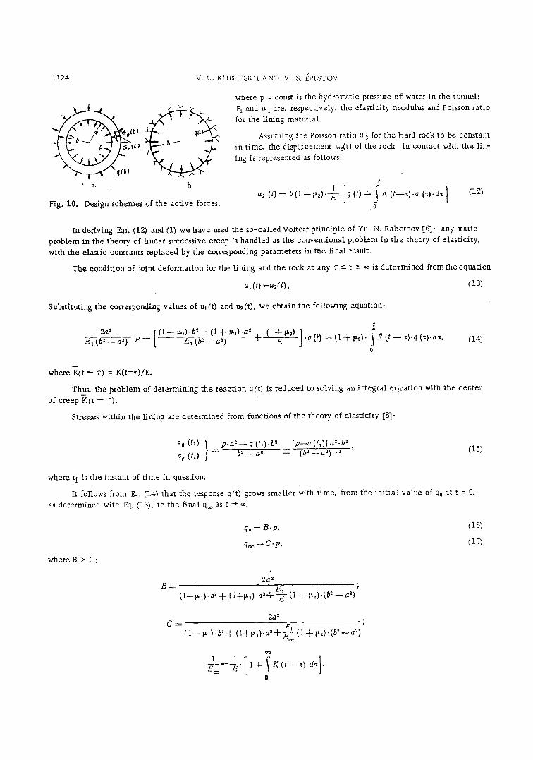
In the combined stressing of the tunnel and hard rock, they sustain radial stresses q(t),variable in t ime and acting on a unit of circumference of radius b. The accepted design schemes are illustrated in Fig. 10. The con- creting job is assumed to be satisfactory, achieving tight and unbroken contact between the rock and the Hning.
We now consider the Lamd problem for an elastic lining acted upon by forces p and q(t) in combined stress-
ing in an infinite homogeneous space having the property of linear successive group.
From the theory of elasticity [8], displacement of the outside surface of the lining, Ul(t) is determined by the
equation
2a 2. O b. [(1 - - ~,). b ~ + (1 + ~,).a 21 u, ( t ) = E, (b 2 - a 2) "p ~, (b~ -a2 ) - - q(t), (11)
1124 V.t. KUBETSKII AND V. S. ERISTOV
�9 a, b
Fig. 10. Design schemes of the ac t ive forces.
where p = const is the hydrostatic pressure o f water in the tunnel;
Et and ~ i are, respectively, the e las t ic i ty modulus and Poisson rat io
for the lining m a t e r i a l
Assuming the Poisson ratio ~ 2 for the hard rock to be constant
in t ime, the disFiacement uz(t) of the rock in contact with the l in-
ing is represented as follows:
t
u2 (t) = b (1 + p.~)"-"E- q (t) + K ( t - - z ) . q ('~).d'~ . J
. 0
(12)
In deriving gqs. (12) and (1) we have used the so-ca l led Volterr pr inciple of Yu. N. Rabotnov [6]: any static
problem in the theory of l inear successive creep is handled as the convent ional problem in t h e theory of elast ici ty,
with the elast ic constants replaced by the corresponding parameters in the final result.
The condi t ion of joint deformat ion for the lining and the rock at any r -< t -< ~ is de te rmined f romthe equat ion
,,, (t) = u~(t), (13)
Substituting the corresponding values of ut(t) and uz (t), we obtain the following equation:
2a 2 [ ( l - - v u l ) - b " + ( l + P . l ) - a 2 (lq--p.2) ] Et ( Y ' - - a 2) "P - - E~ ( Y ' - - a 2) "~ E
t
�9 q (t) = (1 -}- ~2)" .f ~ (t - - "c).q ('~).d'~,
0 (14)
where 7 q t - r) = K ( t - r ) / E .
Thus, the problem of de termining the react ion q(t) is reduced to solving an integral equa t ion with the center
of creep K ( t - - r ) .
Stresses within the l ining are determined from functions of the theory of elast ici ty [8]:
aa(h) } P'a~.~-q(t~)'b2 ~r ( h ) = N - - - - a '
[p--q (td] a~.b z + (b 2_a2) . r2 , (15)
where t i is the instant of t i m e in question.
It follows from ~ . (14) that the response q(t) grows smaller with t ime, from the in i t i a l vaIue of q0 at t = 0,
as determined with ht. (15), to the final q~ as t ~ ~.
qo = B 'p , (16)
qm----C'p, (15)
where B > C:
2a 2 B---- E~ ;
(1--~ ~). b~ + (1+~ , ) . a' +-s (I + ~,)-(b ~ - - a')
2a 2 C = E1 '
( 1 - ~ ) . b' + ( l + ~ , ) . a = + ~ (I + ~2).(b 2 - a')
E---~--~ - 1 + K ( t - - ~).dz �9
o
DESIGN OF LINING FOR DELIVERY TUNNELS 1125
When the creep center K ( t - r) is approximated by Eq. (2), and with q~ = const, we obtain the following
equat ion:
1 1 ~-- = - - e - + 0, + o~.
In designing the lining for del ivery tunnels, the magnitude of tangent ial tensi le stresses on the inner surface,
oO(t) (at r = a)is of particular interest. Analysis of the result obtained shows that o(3(t) r = a increases in t ime from
the in i t ia l va lue of o (3(0) at t = O:
a z + b 2 (1 -- 2B) %(0) =p O~_a~ (1~
to the f inal va lue of o @(~), at t --" *%
a2-[ -- b2(! - - 2 C ) % (co) = p b2 _ aS (19)
Thus the property of creep in hard rocks is an unfavorable factor increasing tensi le stresses in the lining.
We have considered performance of the lining for the genera l case unrestricted by the concrete a lay t ica l ex-
pressions for the creep center K ( t - - r) of the hard rock. A specif ic instance, at K (t - - r ) = ~3X " exp[-- k ( t - - r)
was considered in [9], on somewhat different considerations.
Analysis of the result so obtained shows that the stresses in the rock enclosing the tunnel decrease in t ime,
At the same t i m e these rocks behave l ike a l inear successively creeping only under the condit ion of increasing
stresses. The conclusion is that our theore t ica l description does not exact ly ref lect the response of hard rock under
load. The possible error incurred in applying 13t. (14) can be approximated as follows.
Considering that the response q(t) decreases uniformly with t ime, as demonstrated before, we apply the super-
position pr inciple and represent q(t) as the sum of two actions:
ct (r = qo.-.-[qo--q (t) 1. (2 O)
Thus, the act ion of the l ining on the rock has two components: q~ constant in t ime ; and [q0-- q(t)], nega-
t ive, varying in t ime .
In our instance, considering the difference in response of hard rocks at increasing and decreasing pressures,
the displacement of the rock, u2(t), in contact with the lining is expressed as follows:
t t
[ S ] t z , ( t ) = b ( l - [ - b ~ , ) . - - ~ - 1 + K ( t - - ~ ) . d ~ - - b ( l + b % ) " / Q.qo t
o o
where
.I ~'~ ( t - - ~) _ Q -q '6 K ~ Ct - - ~).
The second component in Eq. (21) is determined on the same considerations as in the analytical description
of hard rock response under the condition of decreasing stresses to the action of local load.
By using Eq. (13), we obtain the equation
t t
I I 1 ~--.q-~- -]- E , ( t - -~ ) [qo - -q (z ) l .d~ - - N . q ( t ) = I + K ( t - - z ) . d z - - D . p , (22) �9 o o

1126
where
V. L. KUBETSKII AND V. S. I~RISTOV
O = G @2_a2) . (1 + ~ ) '
( 1 - - ~ 0 . b ' + (1 + ~l ) .a 2 N = & ( b , _ a 2 ) . ( 1 + v,~)
The response q(t) is determined from integrating Eq. (22), by numerical computation methods. The value of response q~o at t -~ oo can be obtained by solving the algebraic expression
where
( ' ) -}-N.y--qo N-}---~ "{-D.p .= O, (23)
Y = qo - - q~;
I i l - -R- - q.q~ z + K . ( t - - , ) . d , .
o
These calculations show that temile stresses over the inside of the lining, determined from Eq. (23) exceed in some instances the stresses determined with Fxb (19), under the same conditions, by 20=30%. Hence, the con- clusion that the actual deformation properties of hard rocks, allowing for their creep, exert considerable effect on the stress state of the given type of construction as the load decreases. Inasmuch as the rate of creep of fill-concrete is but a fraction of that of rocks in the massif, any accounting for its beneficial effect is practical only at a slow increase of pressure head in the tunnel.
The thickness of a concrete and reinforced-concrete lining is usually so designed as to prevent concrete cracking as the result of tensile stresses.
As demonstrated before, the property of creep in hard rocks sets up additional tensile stresses in the lining. Because of the comparatively low resistance to tensile stresses, crack-resistant concrete lining, without pre-stressing and at sufficiently high pressures in the tunnel, must be extremely thick (at near-normal interior pressures, concrete resistance to stretching is great). It is therefore necessary to look for other effective means, such as prestressing of the lining. Another way, which is more effective in our opinion, is the use of thin, smoothing-out concrete layers in conjunction with deep grouting of the enclosing rocks under high pressure. The pressure necessary for deep cement grouting can be determined as explained before [10].
CONCLUSIONS
1. Field studies show that the creep of rocks under study accounts for a significant portion (up to 50-80%) of the total deformation. Consequently, hard rocks cannot be a.lways regarded as instantaneously deformed. The pat- tern of hard rock deformation is substantially different in loading and unloading.
2. The creep of hard rocks is an adverse factor of stress increase in the lining of the pressure tunnel. It must be taken into consideration in designing.
3. in determining the deformation properties of hard rocks, it is necessary to investigate the deformation pat- tern at both the increasing and decreasing stresses.

DESIGN OF LINING FOR DELIVERY TUNNELS 1127
L I T E R A T U R E C I T E D
1. N.A. Tsytovich, S. B. Ukhov, et al., "Deformations in fissured hard rocks." Third Budapest Conference on Soil Mechanics and Foundation Engineering, Budapest (1918).
2. S.B. Ukhov, N. A. Tsytovich, et al., Some principles of mechanical properties of chlorite schists. Proceedings of the First Congress of the International Society of Rock Mechanics, Lisbon (1966).
3. V .L . Kubetsky and S. B. Ukhov, Towards the investigation of deformations of fissured rock masses based on the theory of creep, Donau-Eurapaiche Konferenz, Bodenmechanik im Strassenbau, Vienna (1968).
4. V.L. Kubetskii and S. B. Ukhov, "Investigation of hard rock creep by the method of static load." Gidrotekh-
nicheskoe Stroitel'stvo, No. 8 (1968). 5. K. R Egorov, Foundation deformation beneath a rigid circular foundation as the resuk of eccentric load.
Osnovaniya i Fundamenty, Voprosy Mekhaniki Gruntov, No. 11, Stroiizdat (1948). 6. Yu. N. Rabotnov, Creep of Construction Elements, [in Russian], Nauka (1966). 7. S .A . Roza and B. D. Zelenskii, Investigation of the Mechanical Properties of Hard Rock Foundations for Hy-
draulic Structures [in Russian], ~nergiya (1967). 8. N . I . Bezukhov, Principles of the theory of Elasticity, Plasticity, and Creep [in Russian], Vysshaya Shkola
(1968). 9. A. Baraket, I~fect of creep on the state of stress in the lining of hydrotechnical pressure tunnels. Bulletin
of the Faculty of Engineering, Alexandria University, Vol. 4 (1966). 10. V.S. ~ristov, "Design and construction of the lining for high-pressure hydraulic tunnels," Gidrotekhnicheskoe
Stroitel'stvo, No. 11 (1968). 11. Zh. S. Erzhanov, The Theory of Rock Creep and Its Application [in Russian], Nauka (1964).
12. F. I-Iautum, High pressure Water tunnels, Water Power, Vol. 19, No. 6, June (1967).