Embed Size (px)
Citation preview

DESIGN OF A HVDC TRANSMISSION LINE
FROM ETHIOPIA TO ISINYA (KENYA)
PROJECT INDEX: 062
BY:
CHARLES JULIUS KILONZI
FI7/1756/2006
SUPERVISOR: DR. WEKESA
EXAMINER: MR. WALKADE
DATE: 23RD MAY, 2011

Objectives:• Feasible HVDC line routing.
• Choice of transmission voltage.
• Conductor type and size.
• Choice of Span, configuration, spacing and clearance.
• Sag and tension analysis.
• Insulation design.
• Choice of Earth wires.
• Design of Line supports and cross-arms.

Introduction• The HVDC interconnector was from Wolayta/Sodo in Ethiopia to
Isinya in Kenya.
• Distance about 1,200km
• Line power capacity = 2,000MW
• A bipolar dc link configuration adopted due to:
Ø Increased reliability.
Ø Stage implementation (as monopolar then bipolar).
• Two converter stations required: one at Wolayta/Sodo and the
other at Isinya.

Main advantages of HVDC over HVAC transmission:• Less reactive power requirement.
• Asynchronous connection.
• Lower losses.
• Greater reliability.
• Less investment cost.
• Stage construction.
• Environment friendly.

Main DC link types:
• Monopolar dc link:
• Bipolar dc link:

HVDC line routing:
Name Distance (km)
1. Wolayta /Sodo - Arba Minch 110
2. Arba Minch – Mega 271
3. Mega to Turbi 107
4. Turbi to Marsabit 131
5. Marsabit to Isiolo 209
6. Isiolo to Isinya 289

HVDC line transmission system map

Transmission voltage
• Transmission voltage choice based on:
• Assumed a bipolar scheme,
• Standard voltage of 500KV was chosen.
1200 1000000V 5.5 ( ) ( ) 570.25KV1.6 100
= + =
)100
P()1.6L(5.5V +=

Conductor type and size• Maximum power transmission assuming certain % voltage
drop:
• Assuming 50% overload, pole resistance/km:
Rdc =
• Assuming a 4-bundled conductor, resistance of each strand given by:
RS =
2
P(max)%V(drop) Rdc L
V=× ×
2
0.013889 / km10 1500 1200
500 = Ω× ×
0.013889 4 0.055556 / km× = Ω
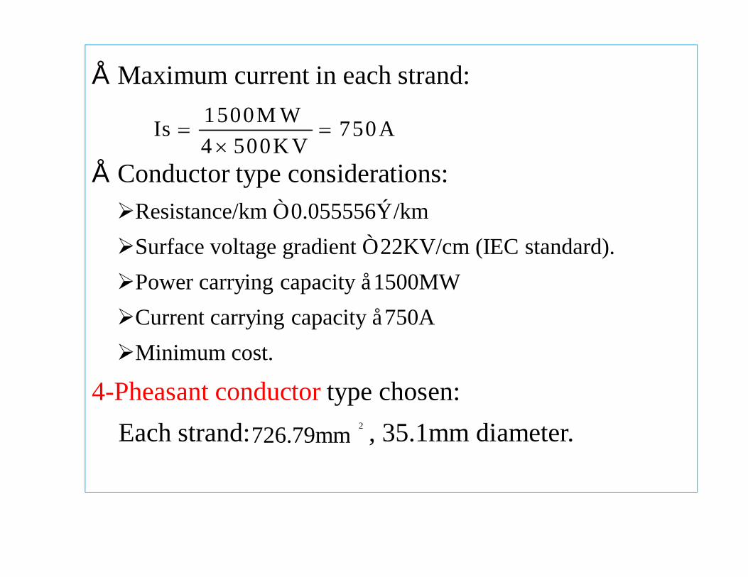
• Maximum current in each strand:
• Conductor type considerations:ØResistance/km ≤ 0.055556Ω/kmØSurface voltage gradient ≤ 22KV/cm (IEC standard).ØPower carrying capacity ≈1500MWØCurrent carrying capacity ≈750A ØMinimum cost.
4-Pheasant conductor type chosen:Each strand: , 35.1mm diameter.
1500M WIs 750A4 500K V
= =×
726.79mm 2

Span, Configuration, ROW and Clearance
• Span of 400m adopted.
• Horizontal conductor configuration (lower tower height).
• ROW (recommended by CIGRE committee).
Ø65m for populated areas.
Ø50m for unpopulated areas.
• Adopted standard conductor clearance of 11m
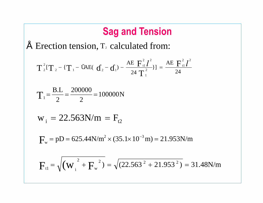
Sag and Tension• Erection tension, calculated from:
1
B.L 200000 100000N2 2T = = =
T2
24AE
]24
AE)αAE([
22t1
21
22t1
121222
FTFθθTTT ll =−−−−
21.953N/mm)10(35.1625.44N/mpD 32wF =××== −
31.48N/m)21.953(22.563) 222w
2
it1 F(wF =+=+=
t2i F22.563N/mw ==
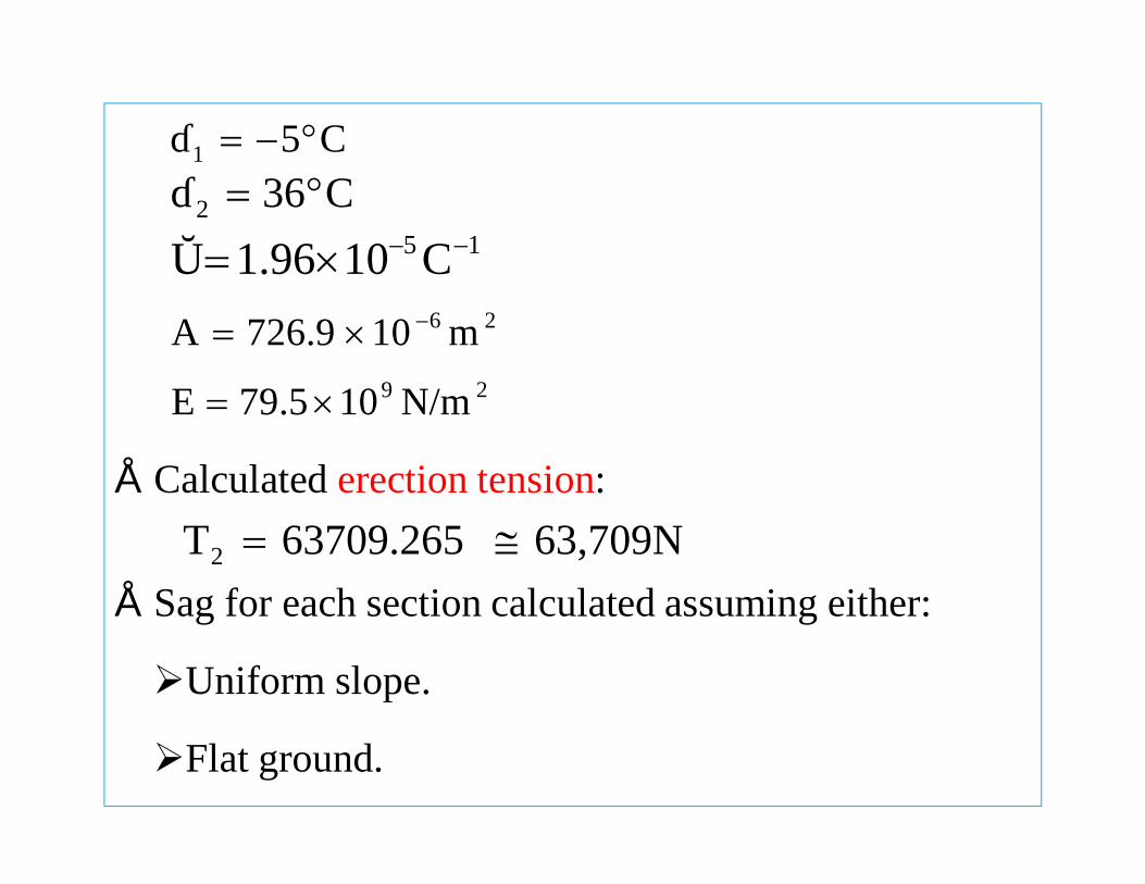
• Calculated erection tension:
• Sag for each section calculated assuming either:
ØUniform slope.
ØFlat ground.
C5θ1 °−=C36θ 2 °=
63,709N63709.265T2 ≅=
15 C101.96α −−×=26 m10726.9A −×=
29 N/m1079.5E ×=

Example: Sag between Wolayta and Arba Minch
• First 30km (altitude between 2000m and1200m).• Assuming uniform slope, elevation:
• Tower level difference:
• Total length:
• Sag:
10.66m275)400sin(1.5sinθh === l
550.5m40022.56310.66637092400
w2Th
c =×××
+=+=l
ll
°=−
= − 1.5275]3000
1200)(2000[θ tan 1
13.42m637098
(550.5)22.5638Tw
S22
c =×
×== l
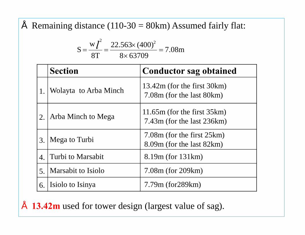
• Remaining distance (110-30 = 80km) Assumed fairly flat:
• 13.42m used for tower design (largest value of sag).
Section Conductor sag obtained
1. Wolayta to Arba Minch 13.42m (for the first 30km)7.08m (for the last 80km)
2. Arba Minch to Mega 11.65m (for the first 35km) 7.43m (for the last 236km)
3. Mega to Turbi 7.08m (for the first 25km)8.09m (for the last 82km)
4. Turbi to Marsabit 8.19m (for 131km)
5. Marsabit to Isiolo 7.08m (for 209km)
6. Isiolo to Isinya 7.79m (for289km)
7.08m637098
(400)22.5638Tw
S22
=×
×== l
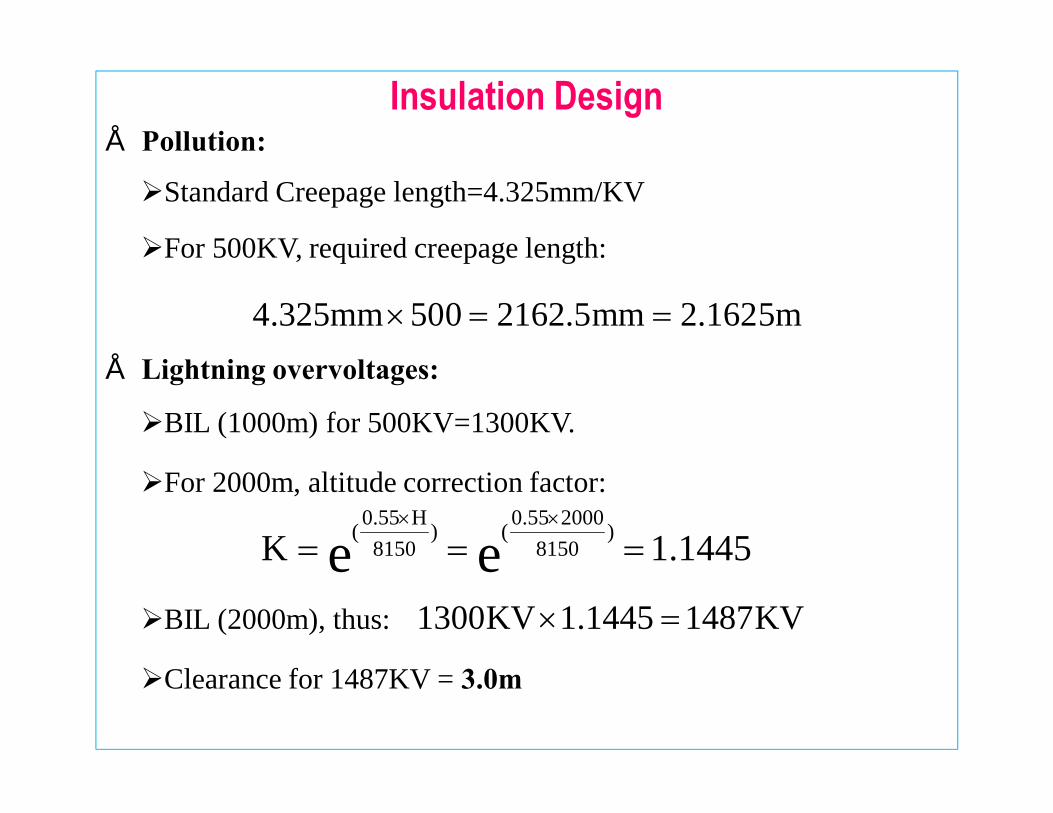
Insulation Design• Pollution:
ØStandard Creepage length=4.325mm/KV
ØFor 500KV, required creepage length:
• Lightning overvoltages:
ØBIL (1000m) for 500KV=1300KV.
ØFor 2000m, altitude correction factor:
ØBIL (2000m), thus:
ØClearance for 1487KV = 3.0m
4.325mm 500 2162.5mm 2.1625m× = =
1.1445K ee )8150
20000.55()8150
H0.55( ===××
1300KV 1.1445 1487KV× =

• Switching overvoltages:
Ø For 500KV (at 1000m) = 1050KV (Switching Insulation level).Altitude correction factor at 2000m:
Switching withstand voltage at 2000m:
Ø Clearance at 1246KV = 4.30m
• 4.30m chosen for tower design (largest among the three).
Earth wires:• Two earth wires (recommended by CIGRE committee).Ø One shield-wire (Galvanized steel wire).Ø OPGW (48-fibre).
• Design sag was:
1.1874K ee )8150
20000.7()8150
H0.7( ===××
1,246KV1.18741050KV =×
12.08m13.42m0%9 =×
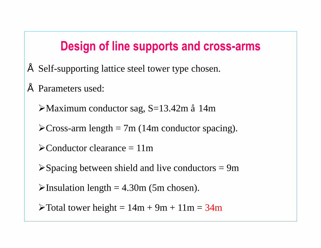
Design of line supports and cross-arms• Self-supporting lattice steel tower type chosen.
• Parameters used:
ØMaximum conductor sag, S=13.42m ≈ 14m
ØCross-arm length = 7m (14m conductor spacing).
ØConductor clearance = 11m
ØSpacing between shield and live conductors = 9m
ØInsulation length = 4.30m (5m chosen).
ØTotal tower height = 14m + 9m + 11m = 34m

Tower diagram

Pole level converter connections• Thyristor valves arranged in 3 twin towers.
• One twin tower with 4 valves.
• Each valve section with 75 thyristors in series.
• Two 6-valve groups in series per pole.
• Star-delta arrangement to provide 30 phase shift.
• 8 Converter transformers, each rated: 500MW, 400/220KV
and 220/400KV , with 1300KV insulation level(LIWL).
o

Valve arrangements• Pole valve arrangement:
• One 6-valve group:

Thyristor calculations
• Thyristor ratings:
• Thyristor firing angle:
cos απ
23 VV L(rms)dc =
°=== −− 32.710.84146cos(220)23
π(250)α 11cos
(220)23π(250)cos α =
2KV1.67KV752
)2500KV(
Vrated ≅=×
=
500A32
)500KV1500MW(
Irated =×
=

Cost estimation
Country Kenya Ethiopia
Costs(Billion Ksh.)
Phase 1 41.95332 29.51016
Phase 2 12.64800 11.55840
Country’s Total Costs
(Billion Ksh.)54.60132 41.06856
Overall Total Costs
(Billion Ksh.)95.66988

Complete HVDC/HVAC system

Conclusions• Successfully obtained the design parameters for the HVDC line:
Ø The most feasible routing.
Ø 500KV transmission voltage.
Ø 11m conductor clearance.
Ø 14m conductor sag.
Ø 7m cross-arm length.
Ø 5m insulation length.
Ø 34m tower height.

Recommendations:
• Detailed converter stations design.• System protection design.

THANK YOU.