Embed Size (px)
Citation preview
Design of Dingley Bypass
Integral Bridges
Dr. Kabir Patoary | Principal Engineer – Bridges | GHD
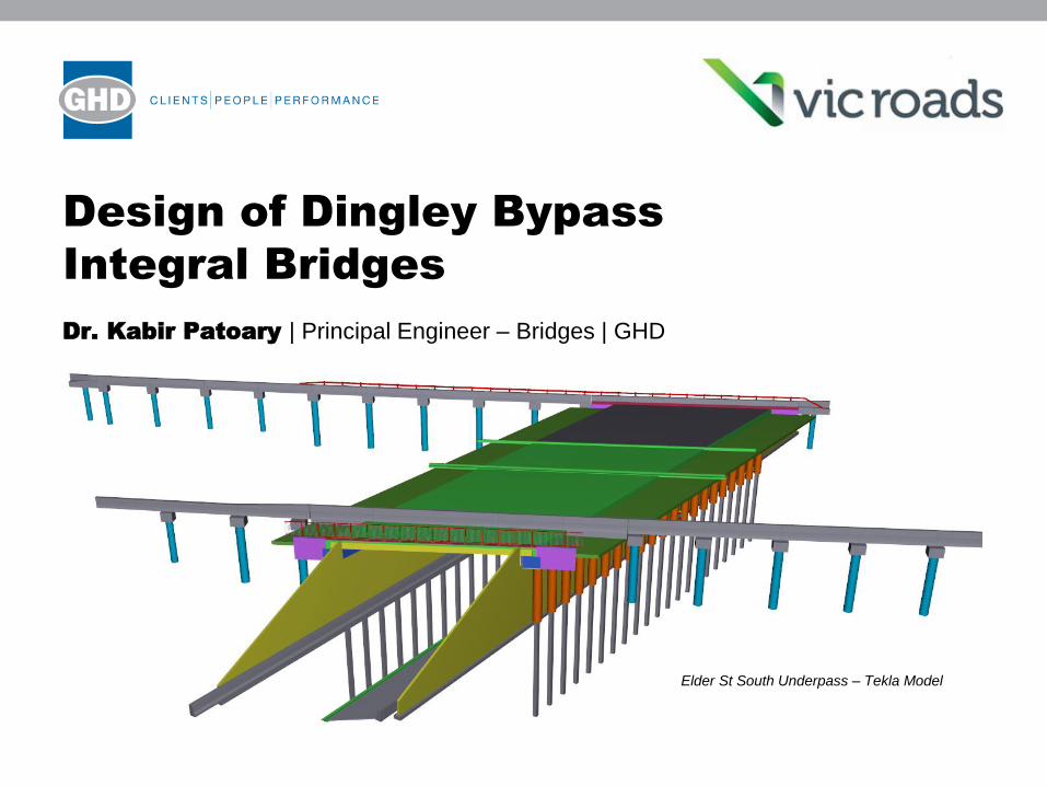
Elder St South Underpass – Tekla Model
Presentation Title
Presentation Outline
1. Overview of Dingley Bypass
2. Design of Integral Bridges
• Why Integral Bridges?
• Code Requirements & Literature
• Design Philosophy
3. Developing a Structural Model
• Mordialloc Settlement Drain Bridge
4. Design of Critical Elements
5. Conclusion
Presentation Title
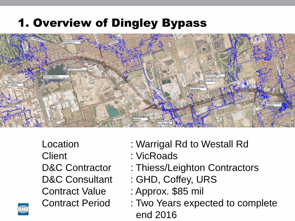
1. Overview of Dingley Bypass
Location : Warrigal Rd to Westall Rd
Client : VicRoads
D&C Contractor : Thiess/Leighton Contractors
D&C Consultant : GHD, Coffey, URS
Contract Value : Approx. $85 mil
Contract Period : Two Years expected to complete
end 2016
Presentation Title
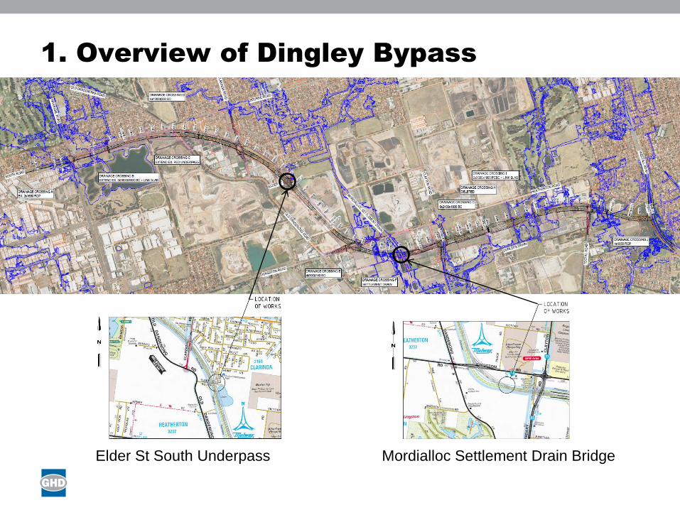
1. Overview of Dingley Bypass
Elder St South Underpass Mordialloc Settlement Drain Bridge

Presentation Title
2. Design of Integral Bridges
Why Integral Bridges?
VicRoads D&C Contract
Long Term Benefits• Improved structural reliability and redundancy
• Improved ride-quality and noise reduction
• Potential for reduced initial cost
• Reduced maintenance requirement
• Reduced traffic disruption
• Lower whole-of-life cost and
• Improvement of bridge appearance

Presentation Title
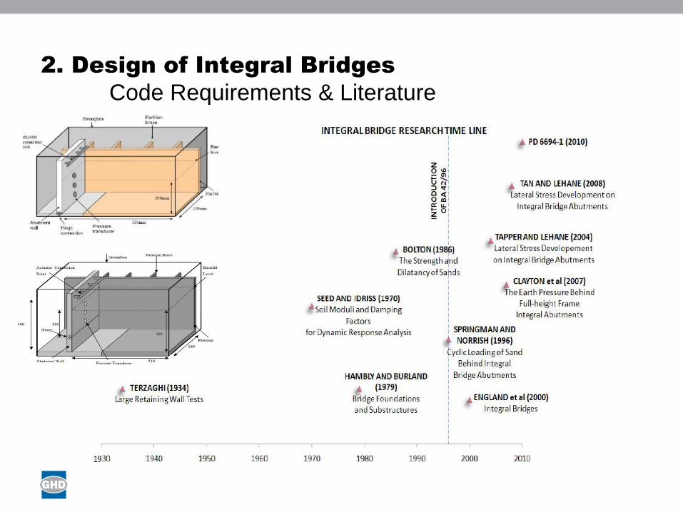
2. Design of Integral Bridges
Code Requirements & Literature
Location Code / Design Guide
Australia
Victoria
AS5100 (no guidance)
VicRoads BTN 2012/003 (references BA 42/96)
UK BA 42/96 (prior to 2011)
PD 6694-1:2011 Section 9 (2011 onwards)
USA Varies State to State
PD 6694 updates the UK recommendations in BA 42/96 to:
• Align with Eurocodes
• Address known issues with BA 42/96
• Embrace latest research in the field
Presentation Title
2. Design of Integral Bridges
Code Requirements & Literature
Presentation Title
2. Design of Integral Bridges
Code Requirements & Literature
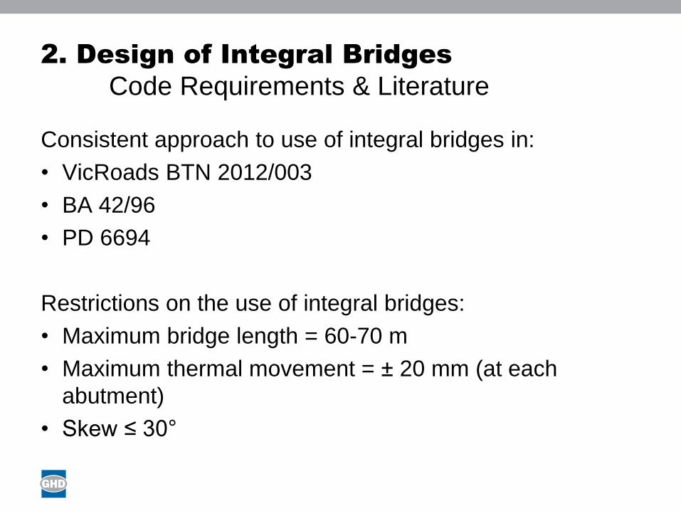
Consistent approach to use of integral bridges in:
• VicRoads BTN 2012/003
• BA 42/96
• PD 6694
Restrictions on the use of integral bridges:
• Maximum bridge length = 60-70 m
• Maximum thermal movement = ± 20 mm (at each
abutment)
• Skew ≤ 30°
Presentation Title
2. Design of Integral Bridges
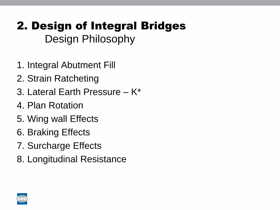
Design Philosophy
1. Integral Abutment Fill
2. Strain Ratcheting
3. Lateral Earth Pressure – K*
4. Plan Rotation
5. Wing wall Effects
6. Braking Effects
7. Surcharge Effects
8. Longitudinal Resistance
Presentation Title
2. Design of Integral Bridges
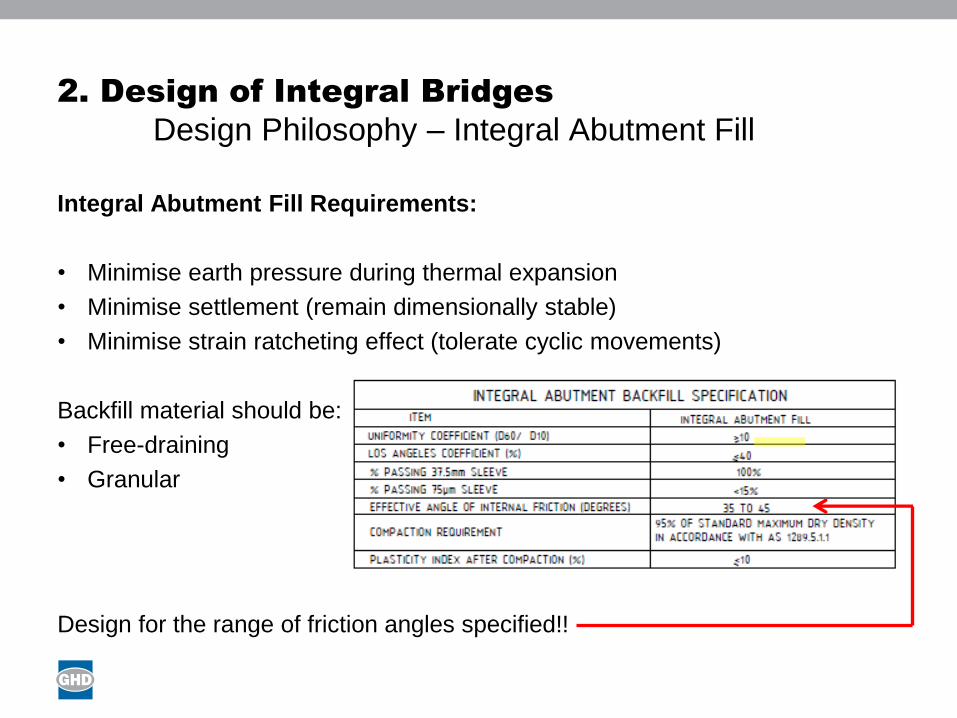
Design Philosophy – Integral Abutment Fill
Integral Abutment Fill Requirements:
• Minimise earth pressure during thermal expansion
• Minimise settlement (remain dimensionally stable)
• Minimise strain ratcheting effect (tolerate cyclic movements)
Backfill material should be:
• Free-draining
• Granular
Design for the range of friction angles specified!!

Presentation Title
2. Design of Integral Bridges
Design Philosophy – Strain Ratcheting
Cyclic thermal expansion causes changes to the lateral earth pressure applied
by the integral abutment fill material.
Strain ratcheting:1. Thermal contraction – gap develops between fill material and abutment back wall
2. Fill material falls into gap – due to vibration/impact of vehicles and surface water runoff
3. Thermal expansion – increased soil density >> increased stiffness >> increased earth pressure
4. Process continues over many years due to seasonal effects - pressure coefficient approaches K*
Design for K* to account for strain ratcheting.
K* calculated based on the total movement of the bridge from the max
contraction position to the max expansion position.
𝑑𝑑 = 𝛼𝐿
2(𝑇𝑚𝑎𝑥 − 𝑇𝑚𝑖𝑛)
dd = design movement
α = coefficient of thermal expansion of the bridge deck
L = bridge length
Tmax = Maximum average bridge temperature
Tmin = Minimum average bridge temperature
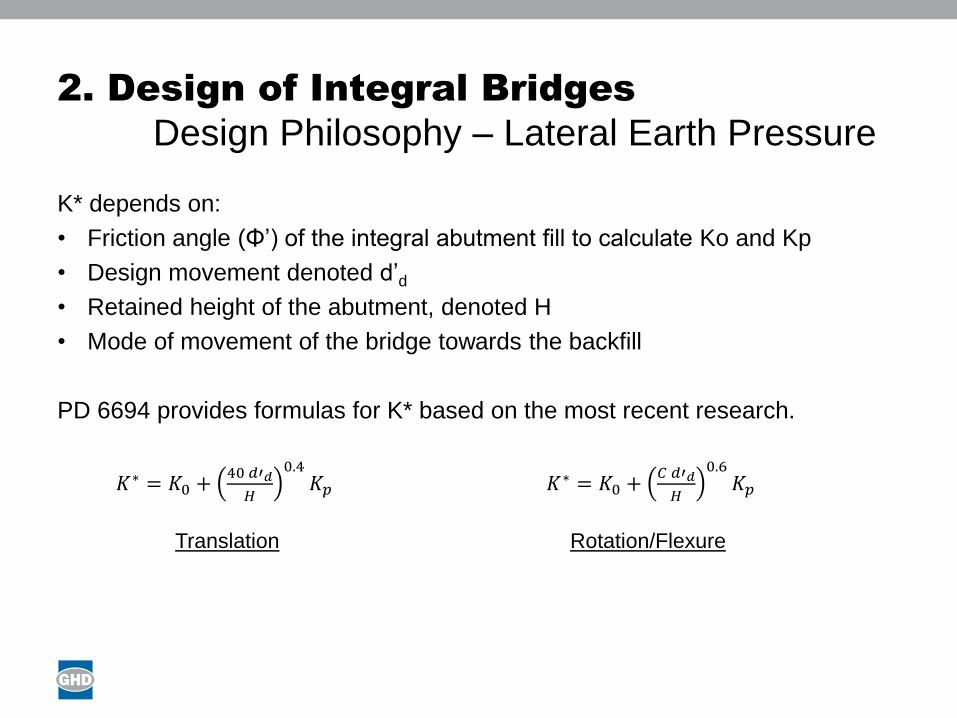
Presentation Title
2. Design of Integral Bridges
Design Philosophy – Lateral Earth Pressure
K* depends on:
• Friction angle (Φ’) of the integral abutment fill to calculate Ko and Kp
• Design movement denoted d’d
• Retained height of the abutment, denoted H
• Mode of movement of the bridge towards the backfill
PD 6694 provides formulas for K* based on the most recent research.
𝐾∗ = 𝐾0 +40 𝑑′𝑑
𝐻
0.4𝐾𝑝
Translation
𝐾∗ = 𝐾0 +𝐶 𝑑′𝑑
𝐻
0.6𝐾𝑝
Rotation/Flexure
Presentation Title
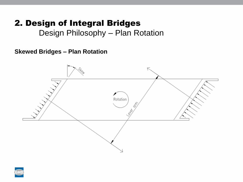
2. Design of Integral Bridges
Design Philosophy – Plan Rotation
Skewed Bridges – Plan Rotation
Presentation Title
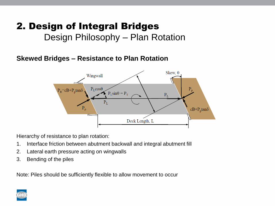
2. Design of Integral Bridges
Design Philosophy – Plan Rotation
Skewed Bridges – Resistance to Plan Rotation
Hierarchy of resistance to plan rotation:
1. Interface friction between abutment backwall and integral abutment fill
2. Lateral earth pressure acting on wingwalls
3. Bending of the piles
Note: Piles should be sufficiently flexible to allow movement to occur
Presentation Title
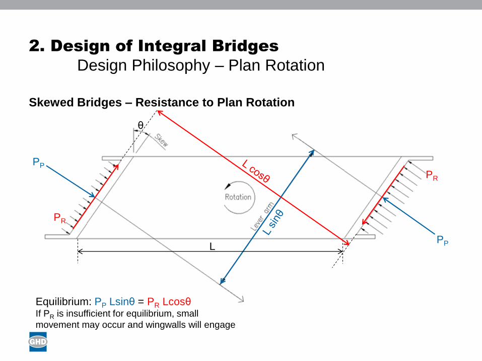
2. Design of Integral Bridges
Design Philosophy – Plan Rotation
Skewed Bridges – Resistance to Plan Rotation
PP
PP
θ
L
PR
PR
Equilibrium: PP Lsinθ = PR LcosθIf PR is insufficient for equilibrium, small
movement may occur and wingwalls will engage
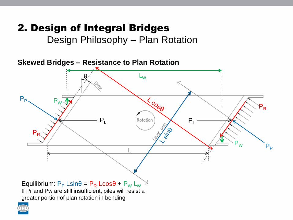
Presentation Title
2. Design of Integral Bridges
Design Philosophy – Plan Rotation
Skewed Bridges – Resistance to Plan Rotation
PP
PP
θ
L
PR
PR
Equilibrium: PP Lsinθ = PR Lcosθ + PW LW
If Pr and Pw are still insufficient, piles will resist a
greater portion of plan rotation in bending
PW
PW
LW
PL PL
Presentation Title
2. Design of Integral Bridges
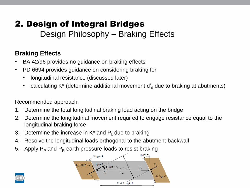
Design Philosophy – Braking Effects
Braking Effects
• BA 42/96 provides no guidance on braking effects
• PD 6694 provides guidance on considering braking for
• longitudinal resistance (discussed later)
• calculating K* (determine additional movement d’d due to braking at abutments)
Recommended approach:
1. Determine the total longitudinal braking load acting on the bridge
2. Determine the longitudinal movement required to engage resistance equal to the
longitudinal braking force
3. Determine the increase in K* and PL due to braking
4. Resolve the longitudinal loads orthogonal to the abutment backwall
5. Apply PP and PR earth pressure loads to resist braking
Presentation Title
2. Design of Integral Bridges
Design Philosophy – Surcharge Effects
Surcharge Effects
• BA 42/96 provides the following guidance:
• “Live load surcharge on backfill should be ignored when calculating the passive
earth pressure mobilised by thermal expansion of the deck”
• “Earth pressures under live load surcharge in the short term should be checked
at ‘at rest’ earth pressure conditions”
• PD 6694 provides the following guidance:
• “Traffic surcharge loading need not be applied in conjunction with K* pressure”
• Denton et al explain that this statement has been included due to:
• Past design practice (pragmatic reasons)
• Some physical justification – “expansion of the bridge deck necessary to
develop K* pressures gives rise to friction effects in the opposite direction
from those that tend to arise from traffic surcharge”… “As a result traffic
surcharge effects and K* pressures are not wholly additive”
Agreement between PD 6694 and BA 42/96: Surcharge should not be combined with
K* earth pressures due to thermal expansion

Presentation Title
2. Design of Integral Bridges
Design Philosophy – Longitudinal Resistance
Longitudinal Resistance at SLS
• Check the movement of the abutment backwall to engage sufficient resistance
• Apply a reduction factor (RF) of 0.5 (recommended by Nicolson)
• Use engineering judgement to determine if the movement is acceptable
Braking + Surcharge + Active Earth Pressure ≤ RF x Passive Earth Pressure
What movement is
required to provide
this resistance?
These forces should be calculated using
the maximum value of Ka from the range
of friction angles specified (eg. 35°-45°)
The braking force
should be resolved
orthogonal to the
abutment
1. Determine K* for required
resistance force
2. Determine the value of d’dbased on the relevant K*
equation
𝐾∗ = 𝐾0 +40 𝑑′𝑑
𝐻
0.4𝐾𝑝
𝐾∗ = 𝐾0 +𝐶 𝑑′𝑑
𝐻
0.6𝐾𝑝
Presentation Title
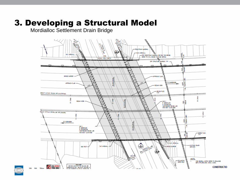
3. Developing a Structural Model
Mordialloc Settlement Drain Bridge
Presentation Title
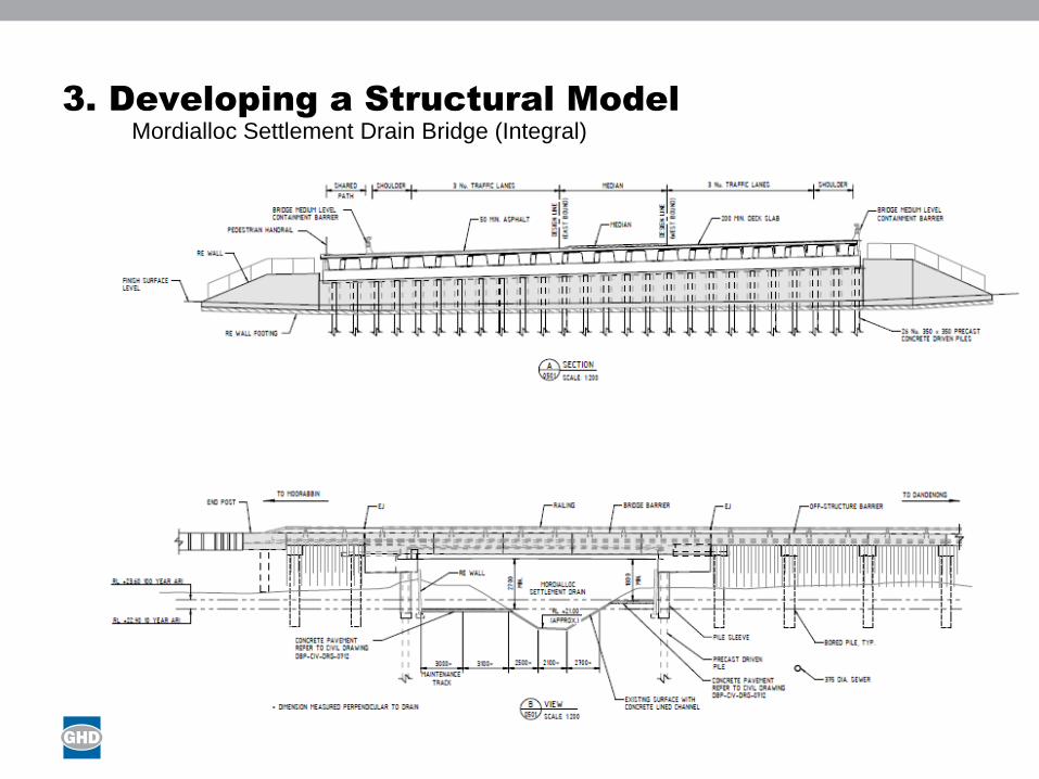
3. Developing a Structural Model
Mordialloc Settlement Drain Bridge (Integral)
Presentation Title
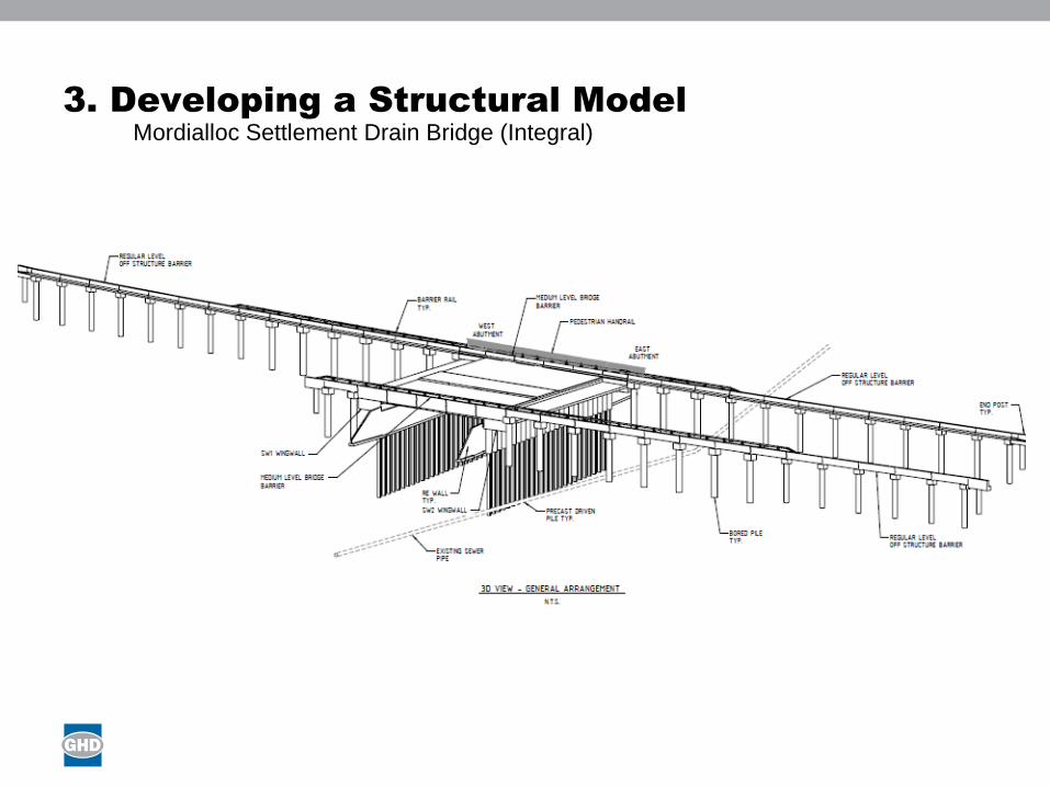
3. Developing a Structural Model
Mordialloc Settlement Drain Bridge (Integral)

Presentation Title
3. Developing a Structural Model
Mordialloc Settlement Drain Bridge (Integral)
Presentation Title
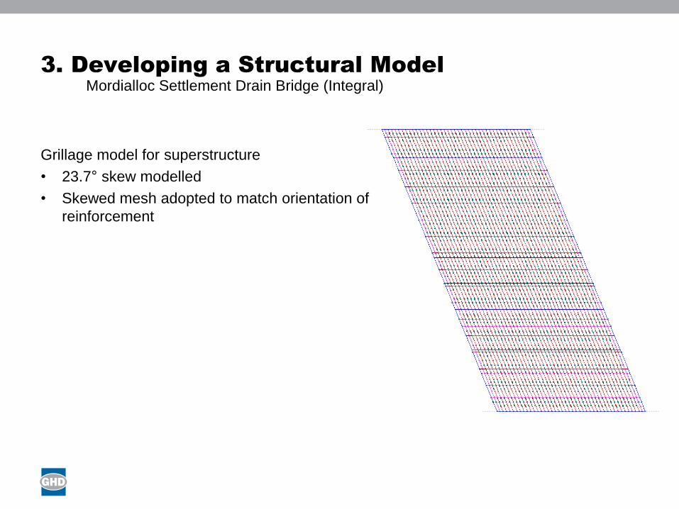
3. Developing a Structural Model
Grillage model for superstructure
• 23.7° skew modelled
• Skewed mesh adopted to match orientation of
reinforcement
Mordialloc Settlement Drain Bridge (Integral)
Presentation Title
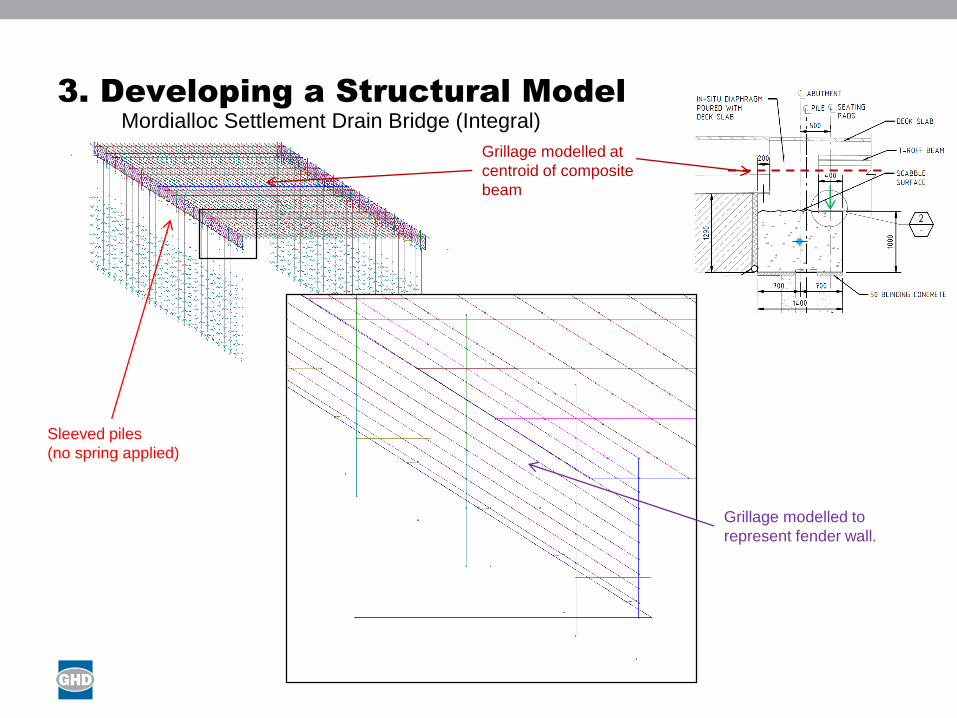
3. Developing a Structural Model
Grillage modelled at
centroid of composite
beam
Mordialloc Settlement Drain Bridge (Integral)
Sleeved piles
(no spring applied)
Grillage modelled to
represent fender wall.
Presentation Title
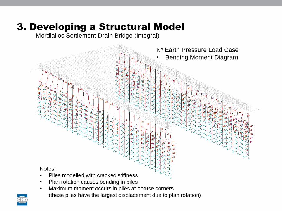
3. Developing a Structural Model
K* Earth Pressure Load Case
• Bending Moment Diagram
Notes:
• Piles modelled with cracked stiffness
• Plan rotation causes bending in piles
• Maximum moment occurs in piles at obtuse corners
(these piles have the largest displacement due to plan rotation)
Mordialloc Settlement Drain Bridge (Integral)

Presentation Title
4. Design of Critical Elements
Critical Elements
• Piles
• Integral Connection
• Fender Wall
• Deck Slab
• Abutment Sill
• Approach Pavement
Presentation Title
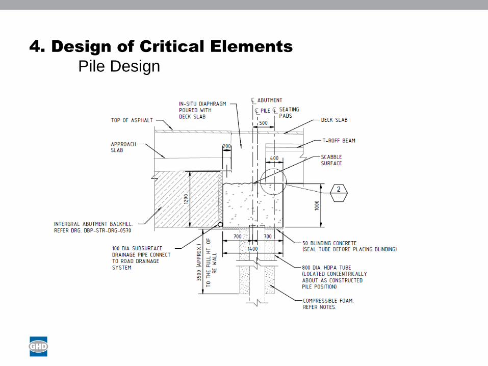
4. Design of Critical Elements
Pile Design
Presentation Title
4. Design of Critical Elements
Integral Connection Design
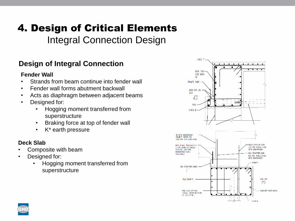
Design of Integral Connection
Deck Slab
• Composite with beam
• Designed for:
• Hogging moment transferred from
superstructure
Fender Wall
• Strands from beam continue into fender wall
• Fender wall forms abutment backwall
• Acts as diaphragm between adjacent beams
• Designed for:
• Hogging moment transferred from
superstructure
• Braking force at top of fender wall
• K* earth pressure

Presentation Title
4. Design of Critical Elements
Approach Pavement
Presentation Title
5. Conclusion
Design Philosophy
• Design integral bridges in accordance with PD 6694 (this supersedes BA
42/96)
• Determine K* based on the range of friction angles in the integral
abutment fill specification
• If possible, resist plan rotation entirely by interface friction to reduce pile
bending moments
• If bridge is working too hard to be designed as fully integral, consider
semi-integral solution to relieve hogging moments at abutments
Design of Critical Elements
• Piles to be sleeved to provide flexibility to movement
• Account for staging effects: locked in moments in piles due to eccentric
DL Beam + DL Slab
• Reinforce approach pavements with geotextiles to reduce likelihood of
surface cracking

Questions?