Embed Size (px)
Citation preview
Civils 06-08
Design of Buried Thermoplastics Pipes
Results of a European research projectby APME & TEPPFA© TEPPFA, March 1999
Civils 06-08
Design of Buried Thermoplastics Pipes
Results of a European research projectby APME & TEPPFA© TEPPFA, March 1999

Civils 06-08
2
Imagine the potential
Organisations supporting the project
TEPPFAThe European Plastics Pipe and Fitting Association
APMEAssociation of Plastics Manufacturers in Europe
Civils 06-08
3
Imagine the potential
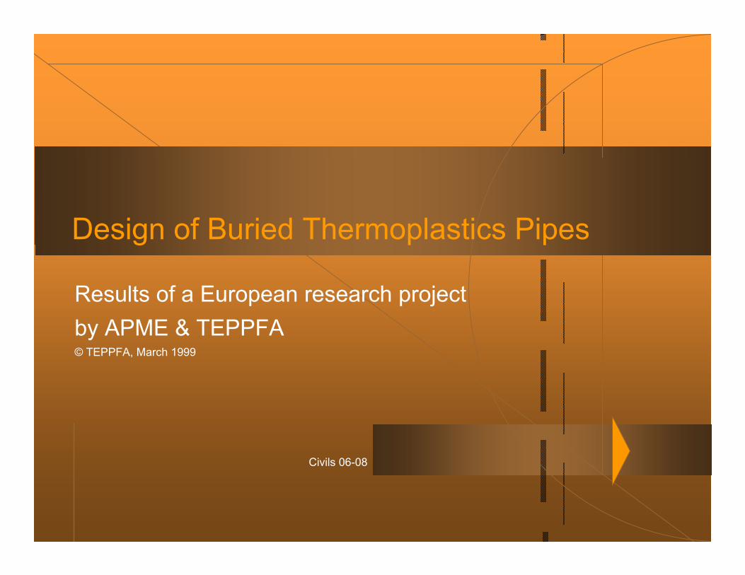
Current situationRigid materials still dominate on many European markets.
Prevailing design practices often tailored for rigid pipes.
Flexibility considered as a weakness.
Designers not always familiar with the behavior of plastic pipes when buried underground.
0
50
100
Scandinavia France Austria Germany UK
Share of Plastic Pipes in Municipal Sewer Pipelines
Plastics Other
Civils 06-08
4
Imagine the potential
Misconceptions about plastics pipes
Deflection increases with installation depth and with traffic load.Pipe ring stiffness is the governing factor determining the performance.Pipe looses stiffness with time, the load bearing capacity reduces.To predict the structural performance an extensive design method is needed.Flexible behaviour is a disadvantage.Deflected pipe looses its discharge capacity and tightness.
TEPPFA and APME started an extensive research project to address these arguments.
Civils 06-08
5
Imagine the potential
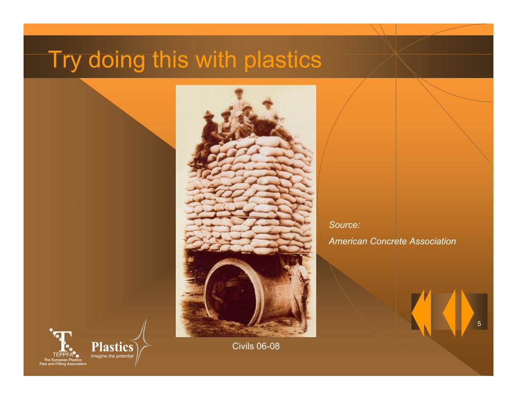
Try doing this with plastics
Source:
American Concrete Association

Civils 06-08
6
Imagine the potential
Objectives of the project
Show the relative importance of the parameters.
Prove flexibility to be a strength instead of a disadvantage.
Develop a design approach in balance with achievable installation quality and actual behaviour.
Contribute to the development of the European standards with real field trials / test results.
Provide material to communicate the project results to the marketplace.
Civils 06-08
7
Imagine the potential
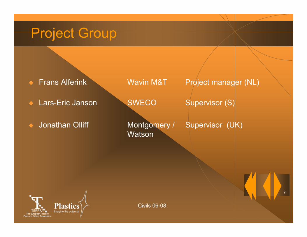
Project Group
Frans Alferink Wavin M&T Project manager (NL)
Lars-Eric Janson SWECO Supervisor (S)
Jonathan Olliff Montgomery / Supervisor (UK)Watson

Civils 06-08
8
Imagine the potential
Steering CommitteeName Company / Association
Ingemar Björklund KWH Pipe / NPG (S) ChairmanHelmut Leitner Solvay / APME (B)Tiem Meijering Polva-Pipelife / FKS (NL)Michael Giay REHAU / ON (A)Dieter Scharwächter Uponor / KRV (D)Jacques Nury Alphacan / STRPE-PVC (F) Constantino Gonzalez ITEPE / ASETUB (E)Alan Headford Durapipe-S&LP / BPF (UK)Jukka Kallioinen Uponor (D)Loek Wubbolt Omniplast (NL)Trefor Jones Wavin (UK)Frans Alferink Wavin M&T (NL) Secretary
Civils 06-08
9
Imagine the potential
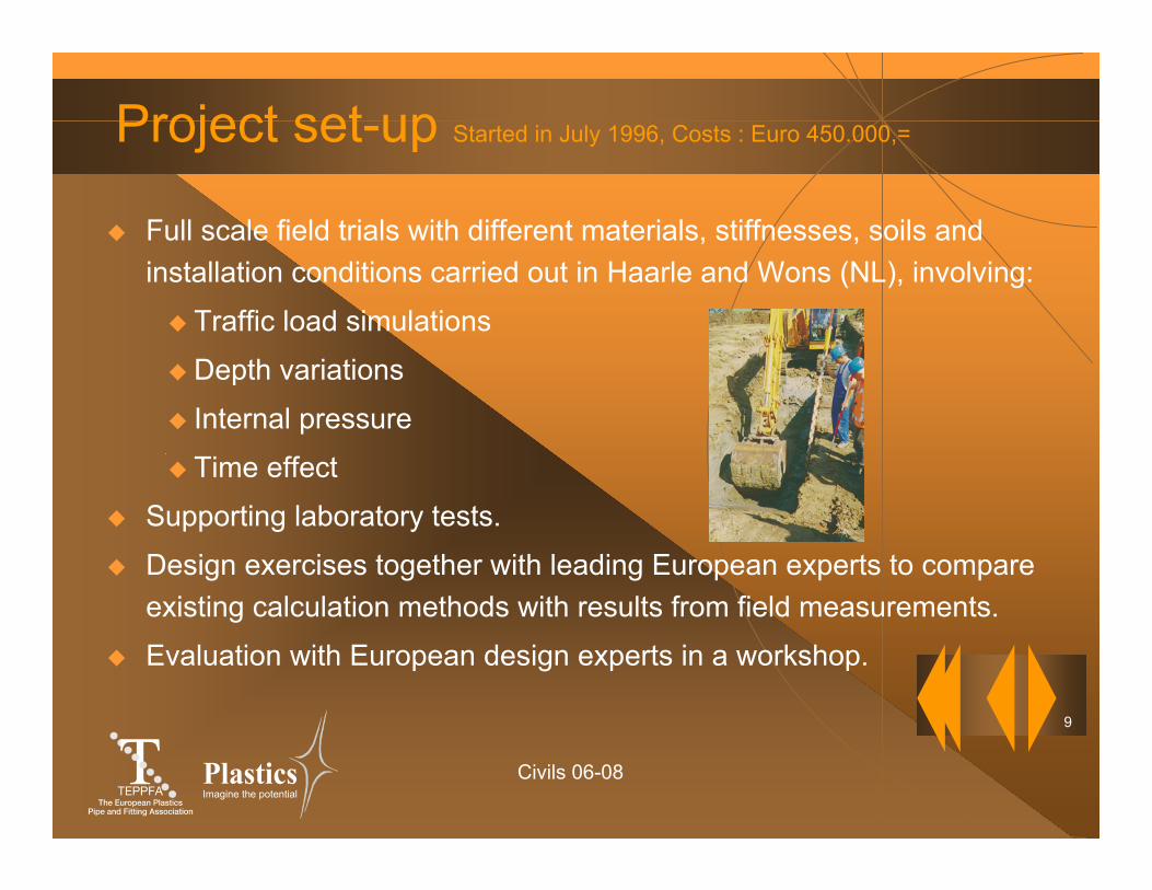
Project set-up Started in July 1996, Costs : Euro 450.000,=
Full scale field trials with different materials, stiffnesses, soils and installation conditions carried out in Haarle and Wons (NL), involving:
Traffic load simulations
Depth variations
Internal pressure
Time effect
Supporting laboratory tests.
Design exercises together with leading European experts to compare existing calculation methods with results from field measurements.
Evaluation with European design experts in a workshop.

Civils 06-08
10
Imagine the potential
European experts involved
Expert Design Method Country
EN 1295Günther Leonhardt ATV A 127 (Germany)Marcel Gerbault Fascicule 70 (France)Walther Netzer ÖNORM B 5012 (Austria)Lars-Eric Janson VAV P70 (Sweden)Jonathan Olliff PSSM (United Kingdom)
OthersHubert Schneider GRP-draft (Germany)Frans Alferink CalVis (The Netherlands)
Tiem Meijering Bossen (The Netherlands)

Civils 06-08
Design of Buried Thermoplastics Pipes
Results of a European research projectby APME & TEPPFA© TEPPFA, March 1999
Civils 06-08
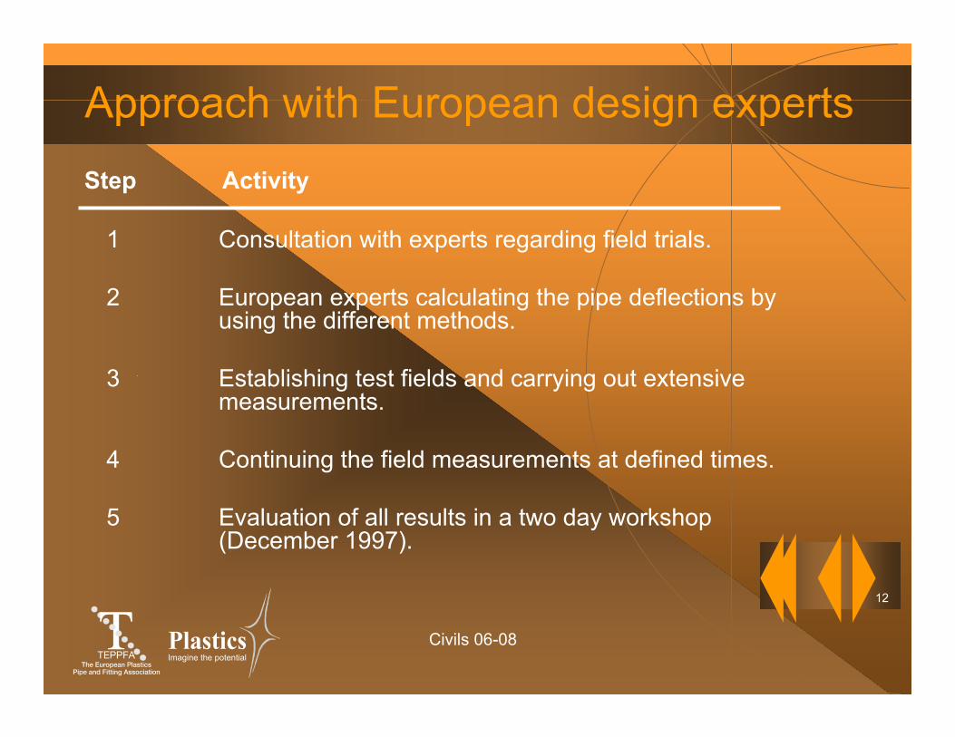
12
Imagine the potential
Approach with European design experts
1 Consultation with experts regarding field trials.
2 European experts calculating the pipe deflections by using the different methods.
3 Establishing test fields and carrying out extensive measurements.
4 Continuing the field measurements at defined times.
5 Evaluation of all results in a two day workshop (December 1997).
Step Activity
Civils 06-08
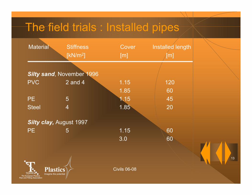
13
Imagine the potential
The field trials : Installed pipes
Silty clay, August 1997PE 5 1.15 60
3.0 60
Material Stiffness Cover Installed length [kN/m2] [m] [m]
Silty sand, November 1996PVC 2 and 4 1.15 120
1.85 60PE 5 1.15 45Steel 4 1.85 20
Civils 06-08
14
Imagine the potential
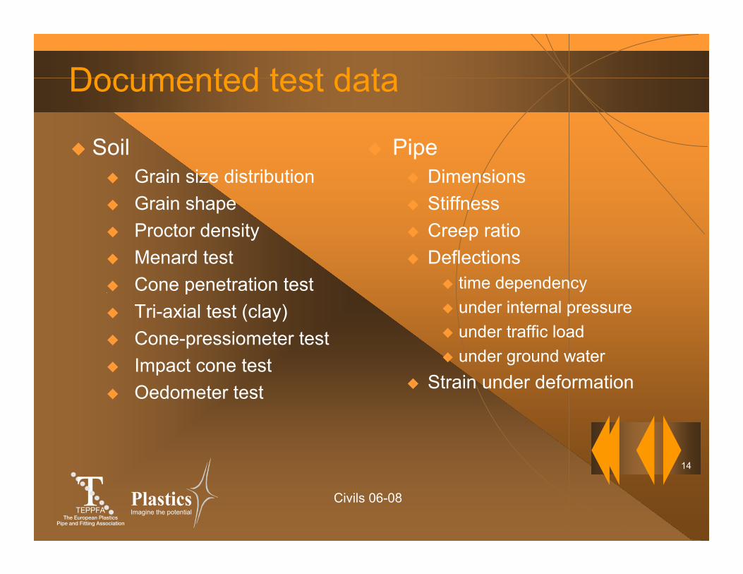
Documented test data
SoilGrain size distributionGrain shapeProctor densityMenard testCone penetration testTri-axial test (clay)Cone-pressiometer testImpact cone testOedometer test
PipeDimensionsStiffnessCreep ratioDeflections
time dependencyunder internal pressureunder traffic loadunder ground water
Strain under deformation
Civils 06-08
15
Imagine the potential
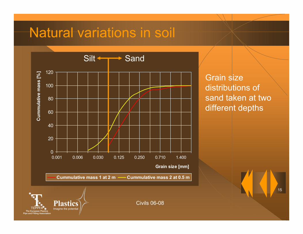
Natural variations in soil
Grain size distributions of sand taken at two different depths
0
20
40
60
80
100
120
0.001 0.006 0.030 0.125 0.250 0.710 1.400
Grain size [mm]
Cum
mul
ativ
e m
ass
[%]
Cummulative mass 1 at 2 m Cummulative mass 2 at 0.5 m
Silt Sand
Civils 06-08
16
Imagine the potential
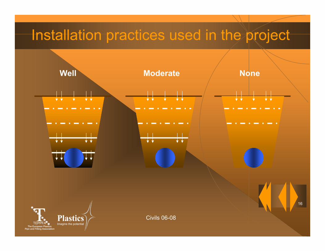
Installation practices used in the project
Well Moderate None
Civils 06-08
17
Imagine the potential
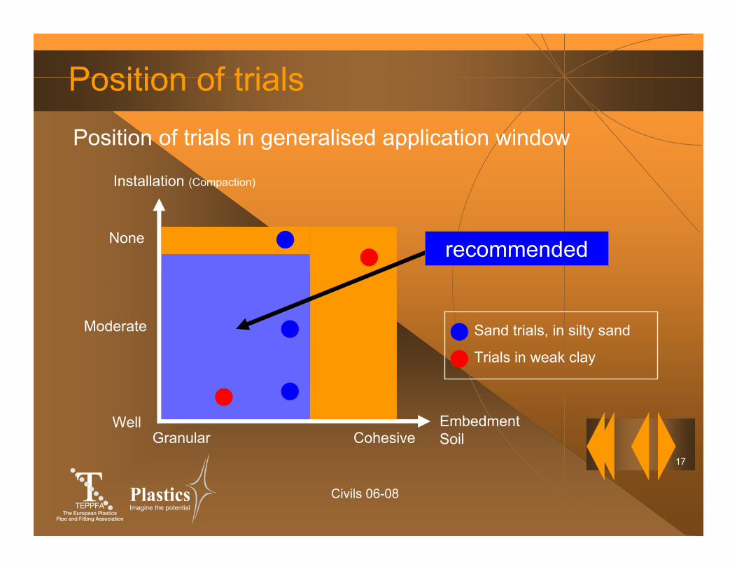
Moderate
None
WellCohesiveGranular
EmbedmentSoil
Installation (Compaction)
Position of trialsPosition of trials in generalised application window
Sand trials, in silty sand
Trials in weak clay
recommended
Civils 06-08
18
Imagine the potential
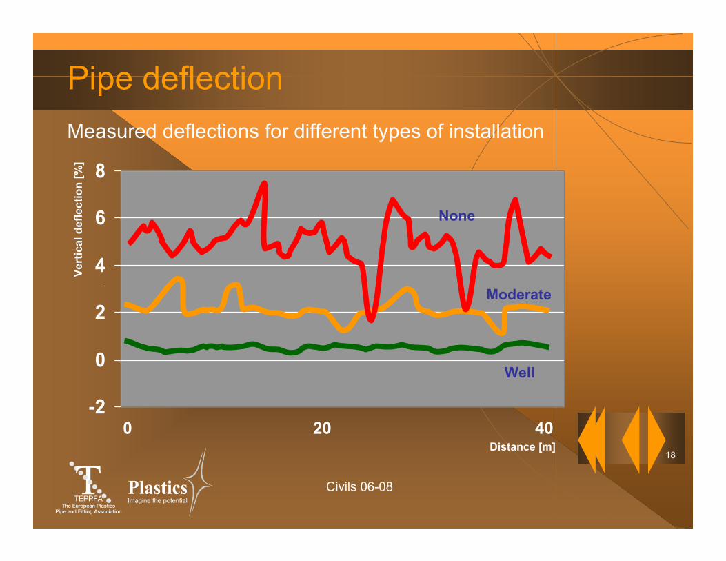
Pipe deflectionMeasured deflections for different types of installation
Distance [m]
Vert
ical
def
lect
ion
[%]
20 400-2
0
2
4
6
8
Well
Moderate
None
Civils 06-08
19
Imagine the potential
Findings from workshop discussions
"Installation of pipeline systems varies from meter to meter depending on many aspects such as workmanship, native soil variations, weather conditions and logistics in the field.”
“Consequently, the installation variability results in variations in ring deflection along the pipeline for flexible pipes and in variations in bending moments along the pipeline for rigid and semi-rigid pipes."
Civils 06-08
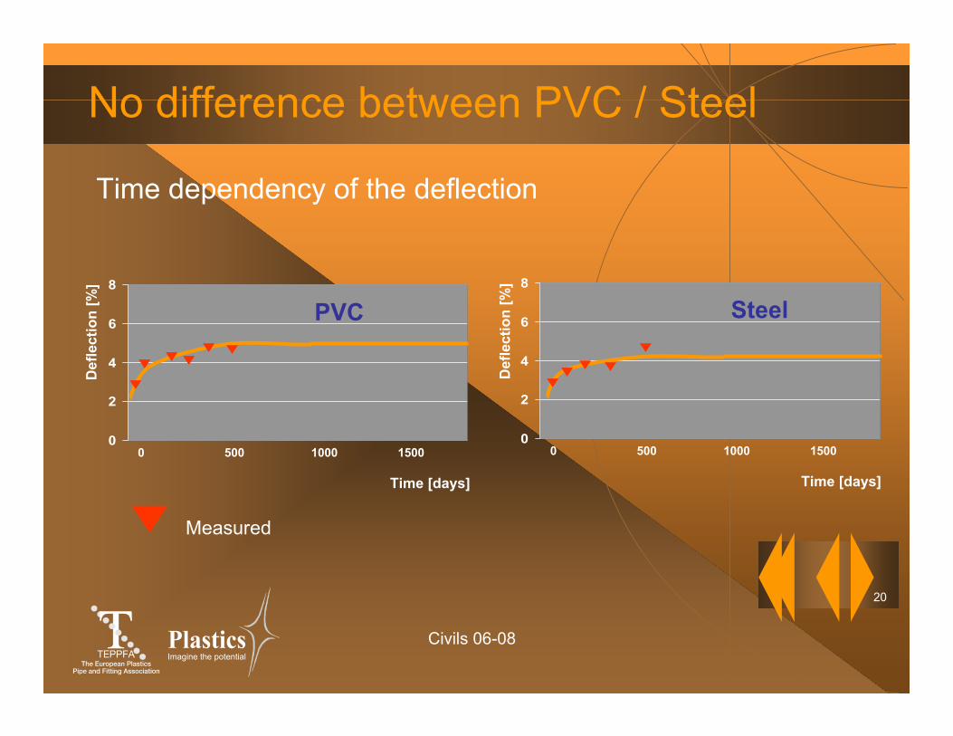
20
Imagine the potential
No difference between PVC / Steel
Time dependency of the deflection
0
2
4
6
8
0 500 1000 1500
Def
lect
ion
[%]
Time [days]
0
2
4
6
8
0 500 1000 1500
Def
lect
ion
[%]
Time [days]
Measured
PVC Steel
Civils 06-08
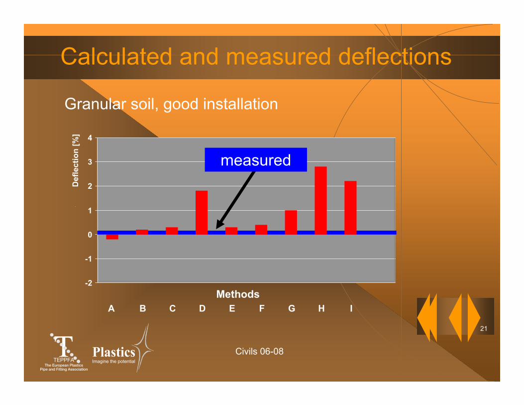
21
Imagine the potential
Calculated and measured deflections
Granular soil, good installation
-2
-1
0
1
2
3
4
Def
lect
ion
[%]
A B C D E F G H IMethods
measured
Civils 06-08
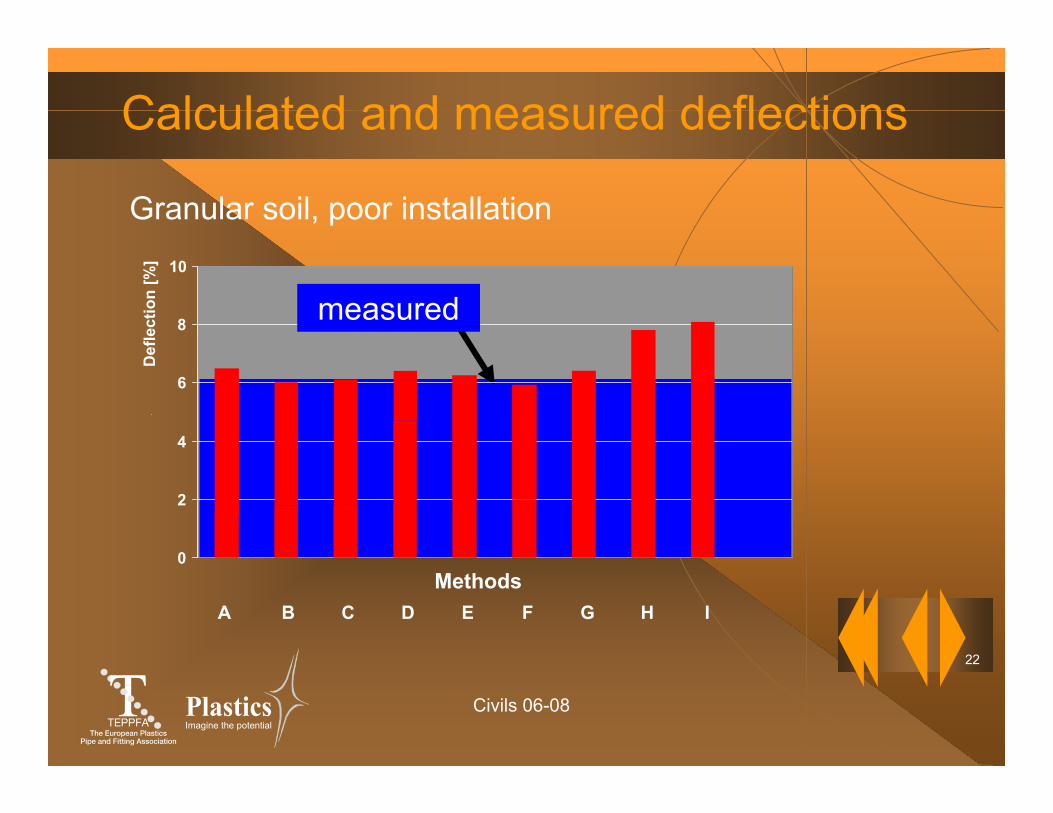
22
Imagine the potential
measured
Calculated and measured deflections
Granular soil, poor installation
0
2
4
6
8
10
Methods
Def
lect
ion
[%]
A B C D E F G H I
Civils 06-08
23
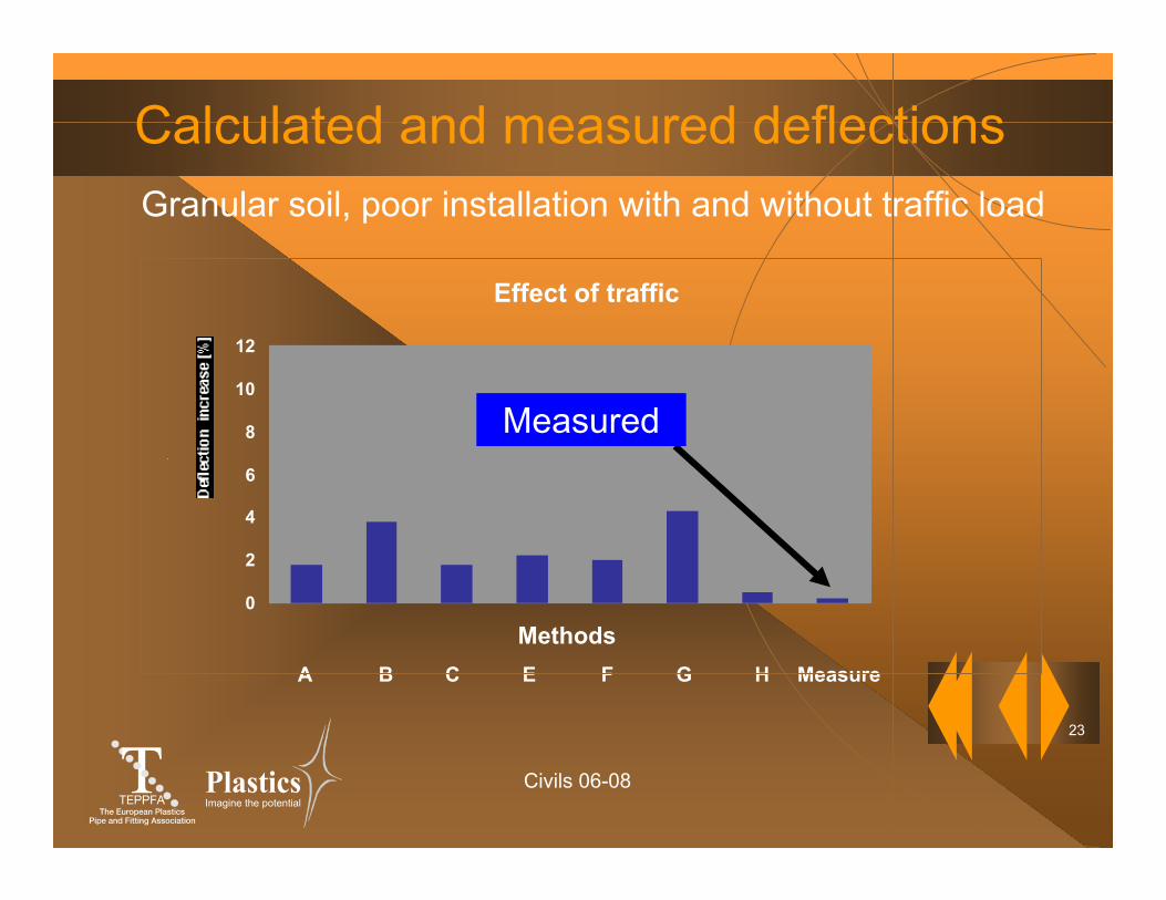
Imagine the potential
Calculated and measured deflectionsGranular soil, poor installation with and without traffic load
A B C E F G H Measure
Effect of traffic
0
2
4
6
8
10
12
Methods
Measured
Civils 06-08
24
Imagine the potential
Summary of the main results
Good understanding of soil-pipe interaction.
20 well documented data sets on the different installations.
Simplified approach with a new design-tool applicable to the majority of pipe installations.
More confidence in plastics pipe performance even under poor installation conditions.
Civils 06-08
25
Imagine the potential
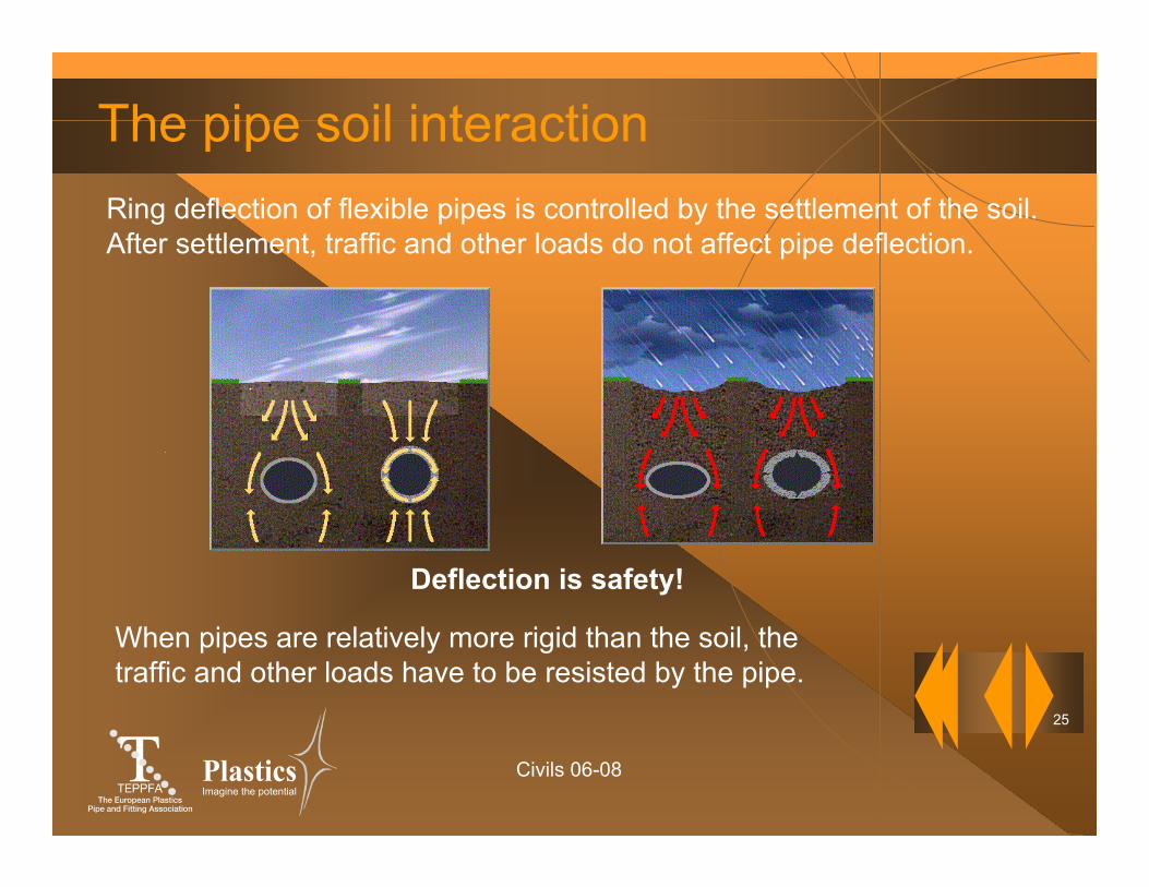
The pipe soil interactionRing deflection of flexible pipes is controlled by the settlement of the soil. After settlement, traffic and other loads do not affect pipe deflection.
Deflection is safety!
When pipes are relatively more rigid than the soil, the traffic and other loads have to be resisted by the pipe.
Civils 06-08
26
Imagine the potential
Facts about deflection
Depth of cover is not relevant.
Traffic load has no significant effect.
Deflection and it's variation depends more on the installation quality than on the pipe stiffness.
Civils 06-08
27
Imagine the potential
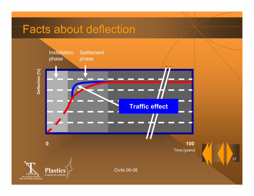
0 100
Facts about deflection
Time [years]
Installationphase
Settlementphase
Def
lect
ion
[%]
Traffic effect
Civils 06-08
28
Imagine the potential
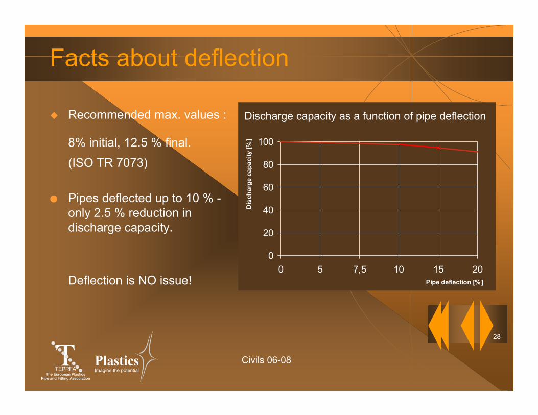
Facts about deflection
Recommended max. values :
8% initial, 12.5 % final.(ISO TR 7073)
● Pipes deflected up to 10 % -only 2.5 % reduction in discharge capacity.
Deflection is NO issue!
0
20
40
60
80
100
0 5 7,5 10 15 20Pipe deflection [%]
Dis
char
ge c
apac
ity [%
]
Discharge capacity as a function of pipe deflection
Civils 06-08
29
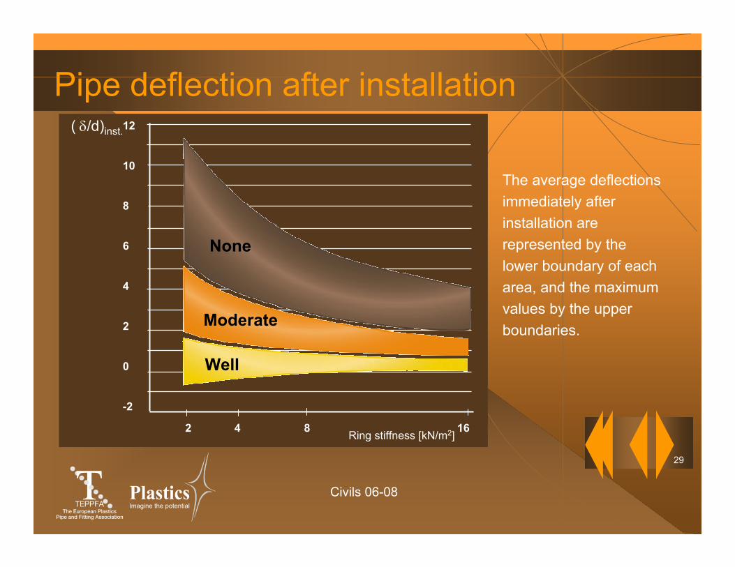
Imagine the potential
Pipe deflection after installation12
10
8
6
4
2
0
-2
Well
( δ/d)inst.
Moderate
None
2 4 8 16Ring stiffness [kN/m2]
The average deflectionsimmediately afterinstallation are represented by the lower boundary of eacharea, and the maximum values by the upper boundaries.
Civils 06-08
30
Imagine the potential
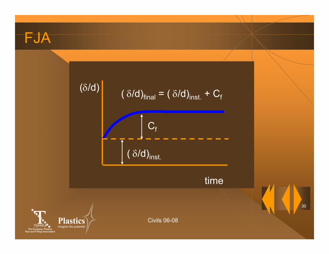
FJA
(δ/d) ( δ/d)final = ( δ/d)inst. + Cf
( δ/d)inst.
Cf
time
Civils 06-08
31
Imagine the potential
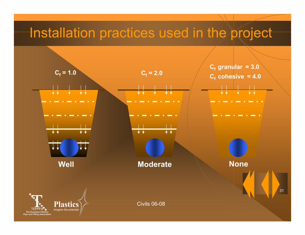
Installation practices used in the project
Well
Cf = 1.0
Moderate
Cf = 2.0
None
Cf granular = 3.0Cf cohesive = 4.0

Civils 06-08
32
Imagine the potential
The paradox“Sophisticated design methods rely on the quality of the input parameters and that the installation is strict according to the prescriptions.
In such cases a “Well” type of installation is obtained, resulting in very low deflections, and hence design is not important in such cases.
When the quality of the input values is less good, as when installations are becoming more difficult and hence limit state conditions are more likely to occur, sophisticated design methods are no longer appropriate”.
Civils 06-08
33
Imagine the potential
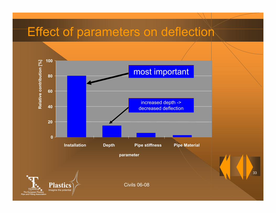
Effect of parameters on deflection
0
20
40
60
80
100
parameter
Installation Depth Pipe stiffness Pipe Material
Rel
ativ
e co
ntrib
utio
n [%
]
most important
increased depth -> decreased deflection
Civils 06-08
34
Imagine the potential
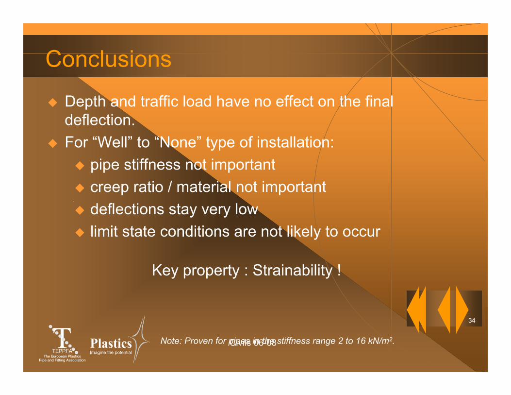
Conclusions
Depth and traffic load have no effect on the final deflection.For “Well” to “None” type of installation:
pipe stiffness not importantcreep ratio / material not importantdeflections stay very lowlimit state conditions are not likely to occur
Key property : Strainability !
Note: Proven for pipes in the stiffness range 2 to 16 kN/m2.
Civils 06-08
35
Imagine the potential
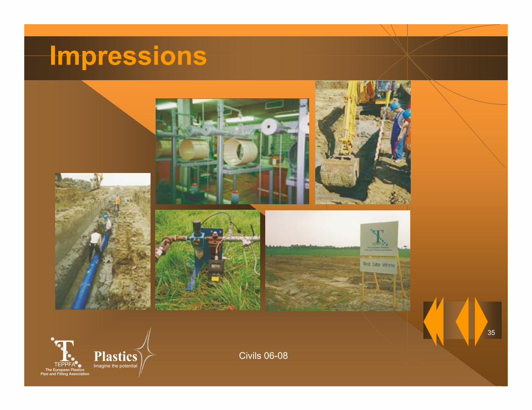
Impressions


![Design of Buried PVC Pipe[2]](https://img.pdfslide.us/doc/110x75/55cf98e2550346d0339a3cfd/design-of-buried-pvc-pipe2.jpg)