Embed Size (px)
Citation preview
UNIVERSITI TEKNIKAL MALAYSIA MELAKA
DESIGN OF AUTOMATIC TOOL CHANGER FOR WELDING
GUN TIP
This report submitted in accordance with requirement of the Universiti Teknikal Malaysia
Melaka (UTeM) for the Bachelor Degree of Manufacturing Engineering (Robotic &
Automation) with Honours.
By
MUHAMAD AZIM BIN AZAMI
FACULTY OF MANUFACTURING ENGINEERING
2008
Alamat Tetap:
18-01-18, Pangsapuri Cheras 4E,
56100, Cheras
Kuala lumpur Tarikh: _________________________
Cop Rasmi: Tarikh: _______________________
** Jika Laporan PSM ini SULIT atau TERHAD, sila lampirkan surat daripada pihak berkuasa/organisasi berkenaan dengan menyatakan sekali sebab dan tempoh laporan PSM ini perlu dikelaskan sebagai SULIT atau TERHAD.
UNIVERSITI TEKNIKAL MALAYSIA MELAKA
BORANG PENGESAHAN STATUS LAPORAN PROJEK SARJANA MUDA
TAJUK: Design of Automatic Tool Changer for Welding Gun Tip
SESI PENGAJIAN: 2008/09 Semester 2 Saya MUHAMAD AZIM BIN AZAMI mengaku membenarkan Laporan PSM ini disimpan di Perpustakaan Universiti Teknikal Malaysia Melaka (UTeM) dengan syarat-syarat kegunaan seperti berikut:
1. Laporan PSM adalah hak milik Universiti Teknikal Malaysia Melaka dan penulis. 2. Perpustakaan Universiti Teknikal Malaysia Melaka dibenarkan membuat salinan
untuk tujuan pengajian sahaja dengan izin penulis. 3. Perpustakaan dibenarkan membuat salinan laporan PSM ini sebagai bahan
pertukaran antara institusi pengajian tinggi. 4. **Sila tandakan (√)
SULIT
TERHAD
TIDAK TERHAD
(Mengandungi maklumat yang berdarjah keselamatan atau kepentingan Malaysia yang termaktub di dalam AKTA RAHSIA RASMI 1972)
(Mengandungi maklumat TERHAD yang telah ditentukan oleh organisasi/badan di mana penyelidikan dijalankan)
Disahkan oleh:
22 May 2009 22 May 2009
DECLARATION
I hereby, declared this report entitled “Design of Automatic Tool Changer for
Welding Gun Tip” is the result of my own research except as cited in references.
Signature : ………………………………….
Author’s Name : MUHAMAD AZIM BIN AZAMI
Date : 13th OCTOBER 2008
APPROVAL
This report is submitted to the Faculty of Manufacturing Engineering of UTEM as a
partial fulfillment of the requirements for the degree of Bachelor of Manufacturing
Engineering (Manufacturing Process) with Honours. The member of the supervisory
committee is as follow:
…………………………………
ABSTRACT
The main focus of this project is on improving the manual method of changing the
welding gun tip. Currently, changing a welding gun tip is done by human, which may
result to delay in production and also can harm the worker safety. The method of the
project is described in this report which includes preliminary research, preliminary
design and design selection. The design for automatic tool changer is presented in
this report. The design is firstly sketched and then drawn using Computer Aided
Design (CAD) software so that future improvement can be done. Solidworks is the
software used for making the design in creating 3 conceptual designs. Design
selection is done based on design properties and required design specification. The
required specification is discussed in order to selecting the best design. The design
must fulfill the main requirement of this project that is, improving the welding gun
tip changing method. In this project, the design is simulated by using the Solid
Works and Working Model software. The aspect of simulation included determining
the efficiency and the effectiveness of the tool changer. In the analysis, the result
shows that the design has better efficiency and effectiveness than manual method.
i
ABSTRAK
Projek ini adalah bertujuan untuk menaik taraf teknik penukaran tip alat kimpalan.
Kebiasanya, pernukaran tip dilakukan dengan mengunakan kekuatan manusia secara
langsung. Ini akan mengurangkan produktiviti dan juga boleh membahayakan
keselamatan pekerja. Langkah – langkah yang perlu dilalu oleh projek turut
diterangkan di dalam laporan ini, iaitu termasuk kajian awal, rekaan awal dan
pemilihan rekaan. Rekabentuk alat penukar automatik turut disertakan di dalam
laporan ini. Rekaan alat dilakaran terlebih dahulu dan kemudian dilukis dengan
mengunakan perisian merekabentuk (CAD) untuk menaik taraf lanjutan. SolidWorks
merupakan perisian merekabentuk yang digunakan untuk merakabentuk 3 rekaan
konsep awal. Cara kerja pemilihan rekaan di buat berdasarkan ciri – ciri rekaan dan
spesifikasi utama yang dikehendaki. Spesifikasi rekaan turut dibincangkan di dalam
laporan ini. Rekaan ini mestilah memenuhi keperluan atau tujuan utama projek iaitu
menaik taraf teknik penukaran tip alat kimpalan. Di dalam projek ini juga, rekaan
yang dibuat akan disimulasikan menggunakan perisian SolidWorks atau Working
Model. Aspek yang berlu ditekankan dalam simulasi adalah menentukan
keberkesanan dan kebolehan rekaan alat penukar . Keputusan dari analisis
menunjukkan alat penukar yang direka mempunyai keberkesanan dan kebolehan
yang baik berbanding teknik yang mengunakan manusia.
ii
ACKNOWLEDGEMENT
First of all I would like to thank Allah the Almighty for His blessing which have help
me to complete the project report and giving me the strength to work along the
project period which one of the requirement for the Bachelor Degree of
Manufacturing Engineering (Robotic & Automation) course.
I would like to give by deepest gratitude to my supervisor, En. Arfauz Bin A.
Rahman and Pn Syamimi Bt Shamsuddin that always being helpful in guiding me
through the whole project period. With the knowledge and experiences that he have,
he shares it by giving brilliant advices that are useful in order to finish up the project.
With the project related activities managed by him shows the full support given in
order for his student to succeed.
I also love to thank my entire family members that continuously giving support and
love which increase my spirit to do the best in what I do. I would like thank to all of
my friends and lecturers that also give some contribution to my project.
Finally, I hope the work of my project will be useful for human being all over the
world
iii
TABLE OF CONTENT
Abstract i
Abstrak ii
Acknowledgment iii
Table of Content iv
List of Tables vii
List of Figures vii
1. CHAPTER 1 : INTRODUCTION 1
1.1 Objective 2
1.2 Scope 2
2. CHAPTER 2 : LITERATURE REVIEW 4
2.1 Welding 4
2.1.1 Method Of Welding 4
2.1.2 Advantages Of Welding 7
2.2 Welding Gun 8
2.2.1 Type Of Welding Gun 8
2.2.2 Anatomy Of Welding Gun 11
2.2.3 Application Of Welding Gun 12
2.2.3.1 Manual Welding Gun 13
2.2.3.2 Robotic Welding Gun 13
2.3 Welding Gun Tip 14
2.3.1 Spot Welding Electrode 15
2.4 Maintenance Of Welding Gun Tip 16
2.4.1 Procedures/Method Used For Maintenance 17
2.4.2 Importance Of Maintenance 18
2.5 Manufacturing Automation 18
2.5.1 Definition Of Automation 19
2.5.2 Benefit Of Automation In Manufacturing 20
2.6 Welding In Automation 22
iv
2.6.1 Benefit Of Automating Welding Process 22
2.7 Computer Aided Design (CAD) 24
2.7.1 Benefit of CAD 25
2.7.2 CAD Software 26
2.7.2.1 SolidWorks 26
2.7.2.2 Automation Studio 29
2.7.2.3 Autodesk AutoCAD 30
2.7.2.4 Autodesk Inventor 31
2.7.2.5 CATIA 33
2.7.2.6 Working Model 34
3. CHAPTER 3 : METHODOLOGY 35
3.1 Overall Completion Planning 35
3.1.1 Project Objectives and Scopes 35
3.1.2 Literature Review Research 36
3.1.3 Design Software Selection 37
3.1.4 Design Selection 37
3.1.5 Design Development 37
3.1.6 Simulating and Analysis of Design 37
3.2 Literature Review Research Methods 38
3.2.1 Key words 39
3.2.2 Correct data 39
3.2.3 Collect Data 39
3.2.4 Source Profile Register 39
3.3 Designing Procedures 40
3.3.1 Sketch Design 40
3.3.2 Select Design 41
3.3.3 Integrate and Analyze Design 41
3.3.4 Finalize Design 41
3.4 Design Selection Methods 41
3.4.1 Listing Design Characteristic 42
3.4.2 Ranking Design Characteristic 42
3.4.3 Researching Existing Design Characteristic 42
3.4.4 Determining the Most Benefit 43
v
3.5 Design Software Selection Methods 43
3.5.1 Software Capability 44
3.5.2 Human – Computer Interaction 44
3.5.3 Ease of Understanding 44
3.5.4 Easy to Use 44
3.6 Design Analysis Methods 45
3.7 Using Design Software 45
3.7.1 SolidWorks 2005 45
3.7.2 Working Model 6.0 48
4. CHAPTER 4 : DESIGN 51
4.1 Basic Design Sketch/Drawing 52
4.1.1 Design 1 52
4.1.2 Design 2 53
4.1.3 Design 3 54
4.2 Design Selection 55
4.3 Design Development 57
4.3.1 Operation Principles 58
4.3.2 Design Placing Location 58
4.3.3 Design Dimension 59
4.3.4 Design Shape 60
4.4 Finalize Design 61
4.5 Robot Design 63
4.6 Design Details 66
4.6.1 Materials and Devices 69
4.6.2 Design dimension 70
4.6.3 Workspace details 71
5. CHAPTER 5 : SIMULATION ANALYSIS AND DISCUSSION 74
5.1 The Benchmark 74
5.2 Rotator Speed 77
5.3 Electrode Tip Change Speed 82
5.4 Electrode Tip Alignment 86
5.5 Stress 89
vi
5.5.1 Interpretation of factor of safety (FOS) values 91
5.6 Simulation of Changing Operation 92
6. CHAPTER 6 : CONCLUSION 96
6.1 Future Improvement 97
REFERENCES 98
APPENDICES 101
A Design Details
B Stepper Motor
LIST OF TABLES
4.1 Different and Similarity between Designs 56
4.2 Pugh Method of Selecting the Design 57
4.3 Material of the Tool Changer 70
5.1 Manual Method of Changing the Welding Gun Tip 74
LIST OF FIGURES
2.1 Fusion Welding 5
2.2 Resistance Spot Welding 6
2.3 Brazing and Soldering 6
2.4 Most Common Welding Methods 7
2.5 SMAW Electrode Holder 8
2.6 MIG Welding 9
2.7 TIG Welding 9
2.8 Two Usual Type of Resistance Welding Mechanism; 10
(A) C – Type and (B) X – Type
2.9 SMAW Electrode Holder Parts 11
vii
2.10 MIG Gun Parts 11
2.11 TIG Welding Torch Parts 12
2.12 Spot Welding Parts 12
2.13 A Man Manually Using SMAW Welding 13
2.14 Spot Welding Gun That Attached To An Arm Robot 14
2.15 Welding Gun Tip/Contact-Tube Location In MIG Welding 14
2.16 Varieties Of Electrode Tip 15
2.17 Wore And Deformed Electrode Tip 16
2.18 Hand Held Electrode Dresser 17
2.19 Automatic Tip Dresser 18
2.20 Steam Power Textile Machine 19
2.21 Fully Automated Production Line 20
2.22 One Of The Product Of CAD 23
2.23 Solidworks Logo 26
2.24 Design Using Solidworks 27
2.25 Design Stress Analysis Using Solidworks 27
2.26 An Assembly Of Drive Shaft 28
2.27 Automation Studio 29
2.28 The Application Of Automation Studio 29
2.29 Autodesk Autocad 30
2.30 Autocad Application In Designing A Model 30
2.31 Autocad’s Drawing Imported Into CNC Machine 31
2.32 Autodesk Inventor 31
2.33 A Part Of Model Consist Several Individual 32
2.34 Part That Is Created Using Autodesk Inventor 32
2.35 CATIA 33
2.36 TOYOTA F1 Model Using CATIA 33
2.37 Human 3D Model For Testing Human View For Inside A Car 34
2.38 Simulation Of Car Crash Using Working Model Software 34
3.1 Flow Chart of Overall Project Planning 36
3.2 A Couple of Internet Search Engine, (A) Google.Com And 38
(B) Yahoo.Com
3.3 Organized Steps in Collecting Data 38
viii
3.4 Design Procedures 40
3.5 Method of Design Selecting 42
3.6 Important Aspect in Design Software Selection 43
3.7 Solidworks Icon Is Selected and Clicked 46
3.8 Solidworks Window 46
3.9 Method of Opening New Workspace or Document; (A) Clicking Menu 47
FILE>NEW, (B) Click the NEW Icon, (C) Click The Menu
NEW DOCUMENT
3.10 New Solidworks Document 47
3.11 Solidworks Workspace 48
3.12 Working Model Icon 49
3.13 Working Model Window 49
3.14 How to Edit Properties 49
3.15 Simulator’s Run Button 50
4.1 Location Of Electrode Tip And Tip Holder 51
4.2 View Of Design 1; (A) All Electrodes Widens, And 52
(B) Four Electrode Retract To Give the Versatility When Welding
4.4 Basic Concept of Design 1 That Is Attached To The End Of 53
Welding Gun Arm
4.5 View of Design 2 with Turret Concept 53
4.6 Design 2 That Is Attached To the Welding Gun 54
4.7 The Basic View of Electrode Gripping Part Of Design 3 54
4.8 Design 3 Basic View 55
4.9 Potential Risk of Human Worker That Could Occur In Regarding Robot 59
4.10 The Working Envelope of A Robot 59
4.11 Suggested Location of the Tool Changer 60
4.12 The Changes in the Design Looks 61
4.13a Automatic Tool Changer For Welding Gun Tip 62
4.13b Design in the Solidworks Work Space 62
4.14a Robot Design 64
4.14b Designed Robot in Solidworks Workspace 64
4.15 General Dimension of the Robot 65
4.16 Maximum Range for Side 65
ix
4.17 The Minimum and the Maximum Opening Of Welding Gun 66
4.18 Tool Changer for Welding Gun Tip 67
4.19 Steps of Changing the Welding Gun Tips 68
4.20 Inside the Changer 69
4.21 Exploded View of Tool Changer Parts 69
4.22 Tool Changer Dimension 71
4.23 One of the Comment Production Line Involving Robot 72
4.24 Production Line in Real-Life 72
4.25 Layout of Tool Location 73
4.26 A Solidworks View of the Tool Changer Location to The 73
Welding Robot
5.1 Manual Welding Gun Tip Changing Method 76
5.2 Tips Alignment 76
5.3 Rotator Set 77
5.4 Rotator Radius 78
5.5 Force Acting to Rotator in Motor View 79
5.6 Graph of Speed-Torque for Motor Model TS31B/GT (Appendix B) 80
5.7 Rotator Rotates At 120o in Order for the Changer To Change Places 81
5.8 Gear Mechanism for Welding Gun Tip Loosening 82
5.9 Work Model in Gear Analysis 83
5.10 Work Model after the Analysis 84
5.11 Data of Velocity from the Results 85
5.12 The Speed of Each the Gear 85
5.13 Unaligned Welding Gun Tip (Courtesy Of FKP Workshop) 86
5.14 Welding Situation for Aligned Tips and Unaligned Tips 87
5.15 Welding Gun and Tool Changer in Solidworks 87
5.16 Tip and the Changer 88
5.17 Step of Tip Changing 89
5.18 Load to the Tool Changer’s Stand 90
5.17 The Material Can Bare High Force 91
5.18 Condition of the Stand Is It Cannot Hold the Load 92
5.19 Robot at Work 93
5.20 Robot Move from Homing Position to the Tool Changer 94
x

5.21 Robot Changing the Tip at the Tip Changing Station 95
5.22 What Robot Could Do the Human 95
xi
CHAPTER 1 INTRODUCTION
Welding gun is one of the important components in welding process. It is used as a
guidance or pointer for an accurate welding. On top of that, it is also acts as a path
way for the electricity to flow from the transformer to the welded metal. Welding
gun is usually handled manually by human. Nowadays it usually attached to a robotic
arm. The usage of welding gun to assist human in welding process is increasing
whether manually or using robot. With the high increment rate of welding gun usage
in industry, the frequency of maintenance is also increasing. One of the important
parts of welding gun that need to be maintained is the tip. The tip is directly exposed
to high temperature and perhaps high pressure, and may need to be maintained
frequently. Usually maintenance of the tips is done by changing the damaged tip with
the new one. Currently, the maintenance procedure is done manually by human and it
is not the best method to be used. Due to limited energy of human, the method result
to longer idle time of production and higher risk of the human safety.
There is a lot of improvement that can be done to improve the changing of welding
gun tip and one of it is by implementing automation. Thus, this project is focusing on
improving the current method of changing the welding gun tip from manual method
to automatic. The improvement need be done due to the ineffectiveness of current
method especially when it is involve productivity and human safety. This project
begins conducting preliminary researching on the current method of changing the
welding gun tip. Upon completion of the preliminary research, suggestions are
brought out to determine the potential design of automated system that may replace
the manual method. The design will be done using computer aided design software
and it is then simulated to analyze the effectiveness in industry.
1
2
1.1 Objectives
The aim of this project is to design an automatic tool changer for welding gun tip.
This aim is achieved through these objectives:-
(a) To study, analyze, and suggest an automated method of changing the welding
gun tip for an industrial robot
(b) To design an automatic tool changer for welding gun tip using Solidworks
software
(c) To simulate and analyze the potential utilization of automated tool changer of
welding gun tip
1.2 Scope of project
By referring the problem in the maintenance of the welding gun tip, some scope must
be accomplished for the improvement to be achieved. The focus of the project is to
study on the current method of changing the welding gun tip. This is by referring the
information on the changing method of the welding gun gathered earlier. Other
useful information include welding, welding gun, automation in manufacturing,
welding in automation, and computer aided design software. The information
gathered from the studies is analyzed so that suggestion of improving the manual
welding tip changing method to automatic is achieved. From the suggestion,
potential design is brought forward and it is done using Solidworks software. The
design is then simulated using Solidworks itself or other analysis software such as
Working Model. The simulation is done due to analyze the properties of the created
design whether it is improving the current method or not.
3
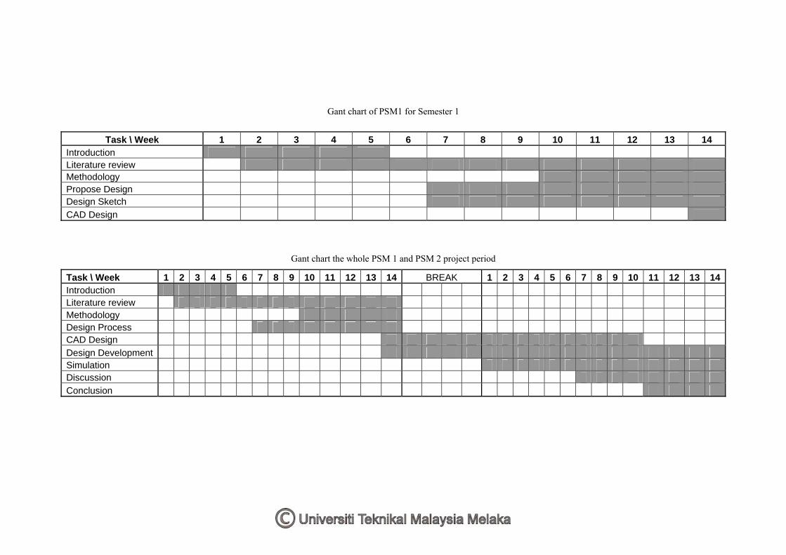
5 6 7 8 9 0 1 2 3 4 1 2 3 4 6 7 8 9 0 1 2
Gant chart of PSM1 for Semester 1
Task \ Week 1 2 3 4 5 6 7 8 9 10 11 12 13 14 Introduction Literature review Methodology Propose Design Design Sketch CAD Design
Task \ Week 1 2 3 4 1 1 1 1 1 BREAK 5 1 1 1 13 14 Introduction Literature review Methodology Design Process CAD Design Design Development Simulation Discussion Conclusion
Gant chart the whole PSM 1 and PSM 2 project period
CHAPTER 2 LITERATURE REVIEW
2.1 Welding
Joining process plays important role in the manufacturing industries, especially in the
assembly sector. The term for joining process is widely in range, covering many
aspects of process that may includes brazing, soldering, adhesive bonding,
mechanical fastening, and welding. Welding is a joining process which involves
metal parts. This process includes melting and joining parts of metal together to form
new item or product.
Balchin (1991) defines welding as uniting pieces of metal part at joint faces. The
faces are melted by heating it with additional similar composition filler metal. Later,
the melted faces which are put close together will stick when it cooled. O’con (2000)
extend the definition by saying that welding is not just sticking metals together, but it
is a total science and the main method of construction and manufacturing used world
wide.
2.1.1 Method of welding
A weld occurs when pieces of metal are joined due to the melting at the interface of
metal and combine it before it is solidified. This process may be caused by heat,
pressure or a combination of both. There are many methods of welding used
currently which follow previously described principles. Kalpakjian and Schmid
(2006) have divide welding into three methods, which is Fusion Welding, Solid-state
Welding and, Brazing and Soldering.
4
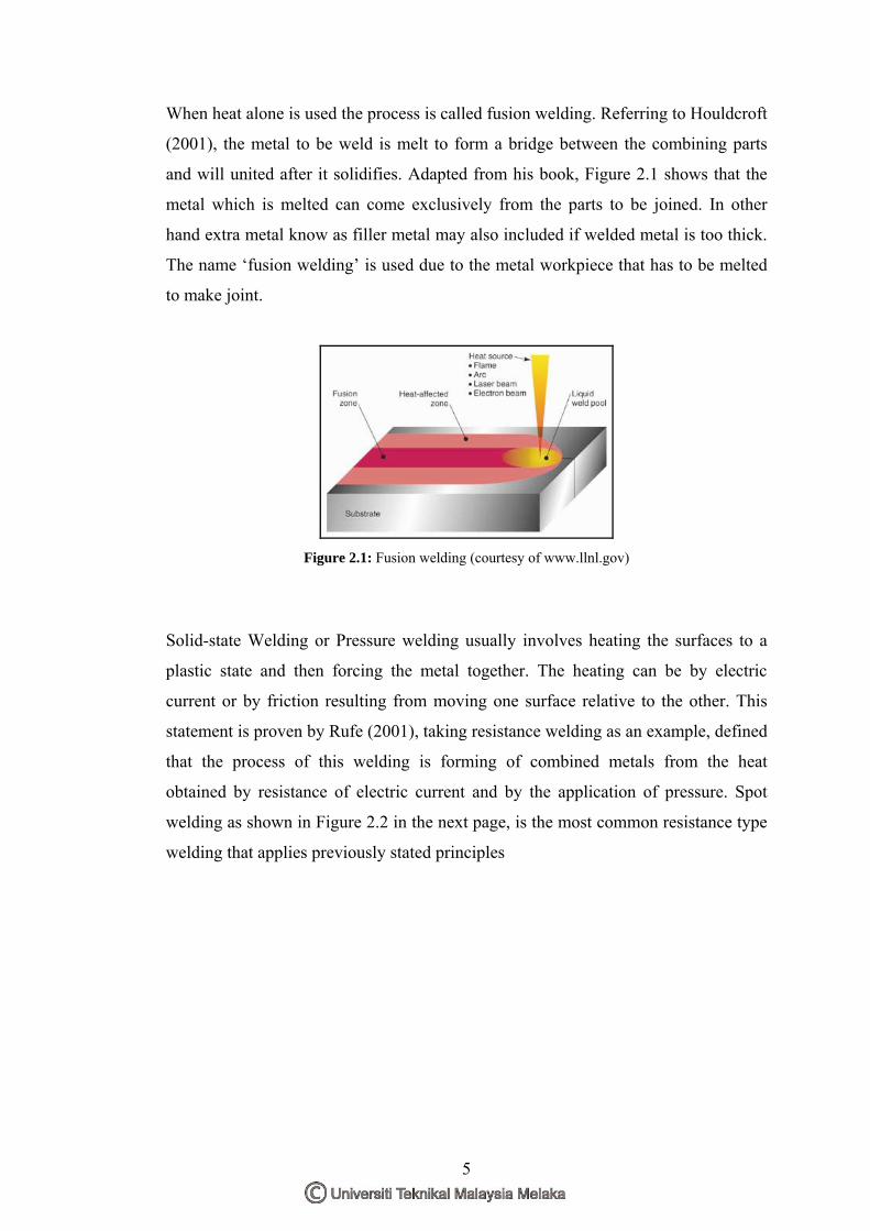
When heat alone is used the process is called fusion welding. Referring to Houldcroft
(2001), the metal to be weld is melt to form a bridge between the combining parts
and will united after it solidifies. Adapted from his book, Figure 2.1 shows that the
metal which is melted can come exclusively from the parts to be joined. In other
hand extra metal know as filler metal may also included if welded metal is too thick.
The name ‘fusion welding’ is used due to the metal workpiece that has to be melted
to make joint.
Figure 2.1: Fusion welding (courtesy of www.llnl.gov)
Solid-state Welding or Pressure welding usually involves heating the surfaces to a
plastic state and then forcing the metal together. The heating can be by electric
current or by friction resulting from moving one surface relative to the other. This
statement is proven by Rufe (2001), taking resistance welding as an example, defined
that the process of this welding is forming of combined metals from the heat
obtained by resistance of electric current and by the application of pressure. Spot
welding as shown in Figure 2.2 in the next page, is the most common resistance type
welding that applies previously stated principles
5
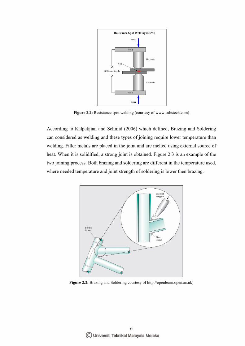
. Figure 2.2: Resistance spot welding (courtesy of www.substech.com)
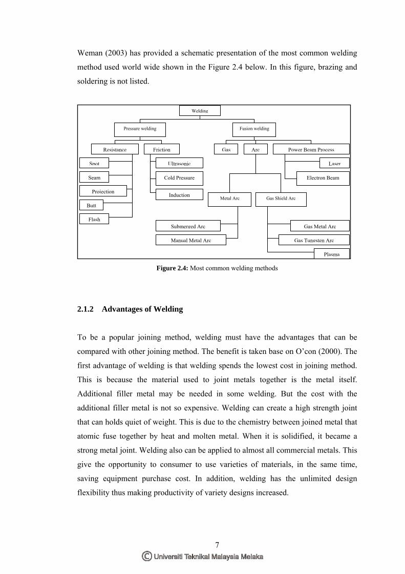
According to Kalpakjian and Schmid (2006) which defined, Brazing and Soldering
can considered as welding and these types of joining require lower temperature than
welding. Filler metals are placed in the joint and are melted using external source of
heat. When it is solidified, a strong joint is obtained. Figure 2.3 is an example of the
two joining process. Both brazing and soldering are different in the temperature used,
where needed temperature and joint strength of soldering is lower then brazing.
Figure 2.3: Brazing and Soldering courtesy of http://openlearn.open.ac.uk)
6
Weman (2003) has provided a schematic presentation of the most common welding
method used world wide shown in the Figure 2.4 below. In this figure, brazing and
soldering is not listed.
Pressure welding Fusion welding
Resistance Friction
Spot
Seam
Projection
Butt
Ultrasonic
Cold Pressure
Induction
Gas Arc Power Beam Process
Laser
Electron Beam
Metal Arc Gas Shield Arc
Manual Metal Arc
Submerged Arc Gas Metal Arc
Gas Tungsten Arc
Plasma
Flash
Welding
Figure 2.4: Most common welding methods
2.1.2 Advantages of Welding
To be a popular joining method, welding must have the advantages that can be
compared with other joining method. The benefit is taken base on O’con (2000). The
first advantage of welding is that welding spends the lowest cost in joining method.
This is because the material used to joint metals together is the metal itself.
Additional filler metal may be needed in some welding. But the cost with the
additional filler metal is not so expensive. Welding can create a high strength joint
that can holds quiet of weight. This is due to the chemistry between joined metal that
atomic fuse together by heat and molten metal. When it is solidified, it became a
strong metal joint. Welding also can be applied to almost all commercial metals. This
give the opportunity to consumer to use varieties of materials, in the same time,
saving equipment purchase cost. In addition, welding has the unlimited design
flexibility thus making productivity of variety designs increased.
7
2.2 Welding Gun
Generally, welding gun is the equipment or tool that acts as a holder for welders to
perform welds. Houldcroft and John (2001) defined that welding torch or gun, which
later being the British standard preferred term, is a device that held by welder for
weld. The term ‘gun’ is use by the International Welding Thesaurus is for a device
that filler wire is feed through it. In another point of view, Weman (2003) defined
that welding gun is an important part of the welding equipment. It brings the
shielding gas, electrode, and welding current to the weld spot.
2.2.1 Type of Welding Gun
The common welding use in fusion welding is the Shielded Metal Arc welding or
SMAW, MIG welding and TIG welding. Each of the welding is different in
operating to perform weld. Thus, different welding gun is needed in order the weld to
be done.
For the Shielded Metal Arc Welding (SMAW), it uses a welding gun known as
electrode holder. This is because SMAW uses an electrode which is made from filler
metal that is coated with flux. The electrode is clipped to the electrode holder which
acts as a holder. It also has the function of electrical connector that will let the
current flow through the electrode to the workpiece to perform weld. Davis (2003)
defined that welding gun for SMAW is also known as electrode holder. It is held by
the operator and firmly grips the electrode, carrying the welding current to it. Figure
2.5 show the common electrode holder used for SMAW
Figure 2.5: SMAW electrode holder (courtesy of http://product-image.tradeindia.com/)
8
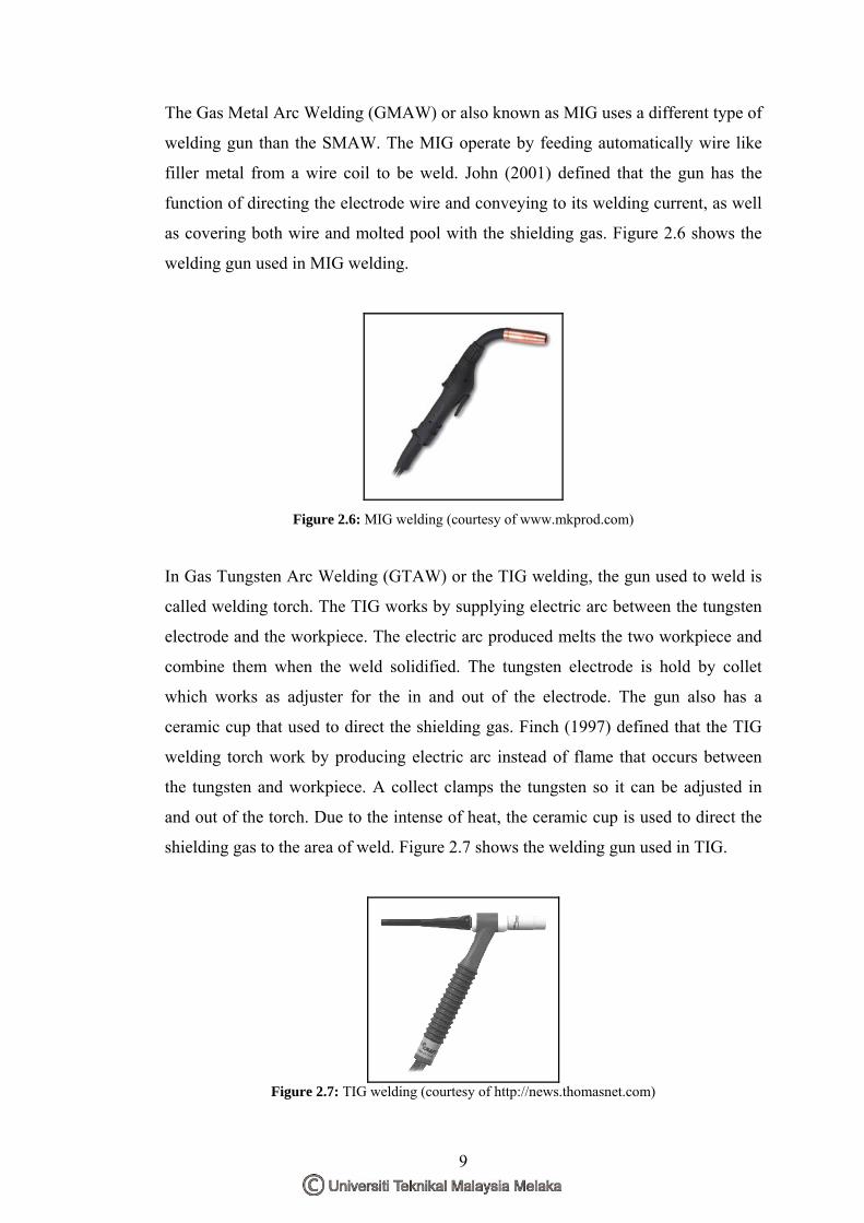
The Gas Metal Arc Welding (GMAW) or also known as MIG uses a different type of
welding gun than the SMAW. The MIG operate by feeding automatically wire like
filler metal from a wire coil to be weld. John (2001) defined that the gun has the
function of directing the electrode wire and conveying to its welding current, as well
as covering both wire and molted pool with the shielding gas. Figure 2.6 shows the
welding gun used in MIG welding.
Figure 2.6: MIG welding (courtesy of www.mkprod.com)
In Gas Tungsten Arc Welding (GTAW) or the TIG welding, the gun used to weld is
called welding torch. The TIG works by supplying electric arc between the tungsten
electrode and the workpiece. The electric arc produced melts the two workpiece and
combine them when the weld solidified. The tungsten electrode is hold by collet
which works as adjuster for the in and out of the electrode. The gun also has a
ceramic cup that used to direct the shielding gas. Finch (1997) defined that the TIG
welding torch work by producing electric arc instead of flame that occurs between
the tungsten and workpiece. A collect clamps the tungsten so it can be adjusted in
and out of the torch. Due to the intense of heat, the ceramic cup is used to direct the
shielding gas to the area of weld. Figure 2.7 shows the welding gun used in TIG.
Figure 2.7: TIG welding (courtesy of http://news.thomasnet.com)
9


![PENGENALAN POLA AKSARA KA-GA-NGA - …repository.unib.ac.id/6831/1/B6 Aksara Ka-Ga-Nga.pdf · RGB harus diubah menjadi citra grayscale terlebih dahulu dengan rumus [2]: ... operasi](https://img.pdfslide.us/doc/110x75/5a7a5b007f8b9a5a588d3b86/pengenalan-pola-aksara-ka-ga-nga-aksara-ka-ga-ngapdfrgb-harus-diubah-menjadi.jpg)