Embed Size (px)
Citation preview
Design of an ECMA368 simulator forevaluating network performance for
electrical substation applications based onIEC618510
MICHELE PASSERINI
Masters’ Degree ProjectStockholm, Sweden September 2008
XR-EE-RT 2008:021

This thesis is dedicated to the memories ofmy grandparents and my aunt Maria.
You will always have a place in my heart..
i
Acknowledgement
First of all, I would like to thank my supervisor at the University of l�Aquila,prof. Maria Domenica Di Benedetto, who gave me the opportunity of havingthe wonderful thesis work experience abroad. I thank also prof. FortunatoSantucci, whose visits in ABB have been a big support for the thesis�suc-cess, and prof. Karl Henrik Johansson, who gave me the possibility to presentmy master thesis at KTH. A huge thank to my supervisor in ABB, JimmyKjellsson, and Krister Landernas for helping me during the last six monthsalways with great professionalism and extreme kindness. The meetings thatwe have done together have always been very useful, and have given me thechance of improving my skills and practical knowledge. A special thank goesto everybody at ABB Corporate Research, but in particular to AutomationNetworks Dept. I have discovered a new reality made up of people who werealways kind to us and ready to help. Thanks to my colleague Alberto, whoshared with me the work experience but also fun in Sweden. I feel to men-tion also all the ABB thesis workers from di¤erent parts of the world, I haveapproached di¤erent cultures and I have discovered that we are not so farfrom each other.I certainly would like to thank my family, who has lien close to me duringthese years of studies, supporting and encouraging me. A thank also to allmy university mates, friends who shared with me �ve years of student life (Ido not mention all of them because I surely will forget someone. I mentiononly Antonio, a great friend who I respect, even if he didn�t mention me inhis acknowledgment, and Cristiano, who shared with me the wonderful highschool period and these �ve years of university as a �atmate).
Thank you All.
Michele Passerini
ii

ABB Corporate Research
Issued by department ZCRD/SECRC/AN
iii
Abstract
An electrical substation is a power distribution center that steps downtransmission voltages to a primary distribution voltage with power trans-formers. It is properly controlled and monitored by a Substation Automa-tion (SA), a reliable system that collects information from the process andrapidly respond to real time events with appropriate actions. Communica-tions inside the SA take place over a substation local area network, whoseperformance can have a critical impact on the whole system. Today, in theMedium voltage segment, the Ethernet-based IEC61850 standard is adoptedto implement protocols and services for communication and in particular op-tical Ethernet is used. However, this usage is both expensive and fragile.The replacement with a UWB technology based on ECMA368 standard in-side waveguides seems to be a good solution.The aim of the thesis has been the implementation of a simulator for eval-
uating performance of a network consisting of several UWB nodes commu-nicating data according to a speci�c scheme (de�ned by an ABB switchgearapplication). The Matlab/Simulink-based TRUETIME simulator has beenextended in order to comply with ECMA368 speci�cs. New implementedfunctionalities have permitted to emulate the transmission of SMV (hardreal-time) and SCADA (best e¤ort) information in the same link and to in-vestigate latency introduced by the communication. Several test cases havebeen analyzed taking into account the two channel access methods allowed byECMA368, DRP and PCA, that permit to create a �exible system which canhandle both periodical high priority data in combination with lower prioritynon-periodic data.
iv
Index terms
Substation Automation, IEC61850, Ultra Wideband, ECMA 368,Distributed Reservation Protocol, Prioritized Channell Access,
TrueTime, Latency.
v
Contents
Contents vi
List of Figures vii
List of Tables viii
List of Acronyms ix
1 Introduction 11.1 Outline Of The Thesis . . . . . . . . . . . . . . . . . . . . . . 3
2 Substation automation systems based on IEC61850 52.1 Electrical substation overview . . . . . . . . . . . . . . . . . . 52.2 Substation Automation systems (SAS) . . . . . . . . . . . . . 72.3 IEC61850 . . . . . . . . . . . . . . . . . . . . . . . . . . . . . 10
2.3.1 Communication architectures . . . . . . . . . . . . . . 112.3.2 Data modeling approach . . . . . . . . . . . . . . . . . 122.3.3 Data exchange model . . . . . . . . . . . . . . . . . . . 132.3.4 SCADA Application . . . . . . . . . . . . . . . . . . . 162.3.5 Generic Object Oriented Substation Event (GOOSE) . 162.3.6 Sampled Measured Values (SMV) transmission . . . . . 17
3 Ultra-Wideband Technology 193.1 UWB description . . . . . . . . . . . . . . . . . . . . . . . . . 193.2 ECMA 368 . . . . . . . . . . . . . . . . . . . . . . . . . . . . 21
4 IEC61850 on ECMA 368 254.1 ECMA368 for SMV transmission . . . . . . . . . . . . . . . . 25
4.1.1 Time Synchronization . . . . . . . . . . . . . . . . . . 26
i
CONTENTS
4.1.2 SMV on Distributed Reservation Protocol (DRP) . . . 274.1.3 SMV on Prioritized Contention Access (PCA) . . . . . 28
4.2 ECMA368 for SCADA transmission . . . . . . . . . . . . . . . 28
5 TrueTime: a Matlab/Simulink-based simulator 305.1 Tool description . . . . . . . . . . . . . . . . . . . . . . . . . . 30
5.1.1 The TrueTime kernel block . . . . . . . . . . . . . . . 315.1.2 The TrueTime wired network block . . . . . . . . . . 335.1.3 The TrueTime wireless network block . . . . . . . . . 35
5.2 Wireless network block implementation details . . . . . . . . . 385.2.1 802.11b/g (WLAN) . . . . . . . . . . . . . . . . . . . . 385.2.2 802.15.4 (WPAN) . . . . . . . . . . . . . . . . . . . . . 395.2.3 Calculation of error probabilities . . . . . . . . . . . . 405.2.4 User-de�ned path-loss function . . . . . . . . . . . . . 42
5.3 TrueTime commands details . . . . . . . . . . . . . . . . . . 43
6 TrueTime Extension 476.1 Introduction . . . . . . . . . . . . . . . . . . . . . . . . . . . . 476.2 DRP implementation for SMV tra¢ c . . . . . . . . . . . . . . 476.3 PCA implementation . . . . . . . . . . . . . . . . . . . . . . 48
6.3.1 Tra¢ c generation . . . . . . . . . . . . . . . . . . . . . 496.3.2 PCA protocol implementation . . . . . . . . . . . . . . 506.3.3 Messages transmission . . . . . . . . . . . . . . . . . . 516.3.4 Proxy implementation . . . . . . . . . . . . . . . . . . 51
6.4 Wireless network mask modi�cation . . . . . . . . . . . . . . . 52
7 Simulation Setups 55
8 Simulation Results 618.1 SMV and SCADA data transmission in a superframe structure 618.2 SMV and SCADA data transmission in a contention-based
structure . . . . . . . . . . . . . . . . . . . . . . . . . . . . . . 64
9 Conclusions 70
A Simulation Results Plots 72
Bibliography 87
ii
List of Figures
2.1.1 Example of an outdoor electrical substation . . . . . . . . . . 62.1.2 Example of an indoor electrical substation . . . . . . . . . . . 62.2.1 Example of an Intelligent Electronic Device (IED) . . . . . . . 72.2.2 Logical scheme of the three levels of a Substation Automation
system . . . . . . . . . . . . . . . . . . . . . . . . . . . . . . . 82.2.3 Vertical communication in the substation automation system . 92.2.4 Horizontal communication in the substation automation system 102.3.1 Examples of Ethernet architectures in Substation Automation 122.3.2 IEC61850 Class Model . . . . . . . . . . . . . . . . . . . . . . 132.3.3 The mapping of the IEC 61850 data model and services . . . . 142.3.4 Two-Party-Application-Association . . . . . . . . . . . . . . . 152.3.5 MultiCast-Application-Association . . . . . . . . . . . . . . . 152.3.6 Example of GOOSE transmission . . . . . . . . . . . . . . . . 172.3.7 Process connection with serial communication for SMV trans-
mission . . . . . . . . . . . . . . . . . . . . . . . . . . . . . . . 18
3.1.1 Comparation between Narrow-band and UWB PSDs . . . . . 203.2.1 ECMA368 Spectrum Allocation . . . . . . . . . . . . . . . . . 213.2.2 ECMA368 Superframe structure . . . . . . . . . . . . . . . . . 223.2.3 PCA protocol behaviour . . . . . . . . . . . . . . . . . . . . . 24
5.1.1 The TrueTime 1.5 block library . . . . . . . . . . . . . . . . . 315.1.2 The dialog of the TrueTime kernel block . . . . . . . . . . . . 325.1.3 The dialog of the TrueTime network block . . . . . . . . . . . 345.1.4 The dialog of the TrueTime wireless network block . . . . . . 365.2.1 Probability density function for a received symbol when using
binary phase shift keying and additive white Gaussian noise . 41
iii
LIST OF FIGURES
6.3.1 PCA algorithm �ow chart . . . . . . . . . . . . . . . . . . . . 506.4.1 Wireless Network block parameters for ECMA368 . . . . . . 53
7.0.1 TrueTime blocks for ECMA368 simulations . . . . . . . . . . . 557.0.2 SMV on DRP with variable number of SMV samples per MAC
frame . . . . . . . . . . . . . . . . . . . . . . . . . . . . . . . . 577.0.3 SMV on DRP with �xed number of SMV samples per MAC
frame . . . . . . . . . . . . . . . . . . . . . . . . . . . . . . . . 587.0.4 TMT of MBOA DRP and PCA . . . . . . . . . . . . . . . . . 59
8.1.1 Latency trends for SMV data using DRP . . . . . . . . . . . . 628.1.2 Latency plots for a 9 nodes con�guration . . . . . . . . . . . . 638.1.3 Average latency trends for SCADA packets using DRP . . . . 648.2.1 Latency trends for SMV packets using PCA . . . . . . . . . . 658.2.2 Maximum latency trends for SMV packets . . . . . . . . . . . 668.2.3 Average latency trends for SMV packets . . . . . . . . . . . . 678.2.4 Probability of latency > 3 ms . . . . . . . . . . . . . . . . . . 688.2.5 Average latency trends for SCADA packets . . . . . . . . . . . 69
iv
List of Tables
3.2.1 Data rates in MB-OFDM PHY . . . . . . . . . . . . . . . . . 21
7.0.1 Parameters for SMV and SCADA data . . . . . . . . . . . . . 59
v
List of Acronyms
AC Access Category
AIFS Arbitration Interframe Space
AC BE Access Category - Best E¤ort
AC BK Access Category - Background
AC VI Access Category - Video
AC VO Access Category - Voice
ACSI Abstract Communication Service Interface
BP Beacon Period
BPSK Binary Phase Shift Keying
CSMA/AMP Carrier Sense Multiple Access/Arbitration on Message Pri-ority
CSMA/CA Carrier Sense Multiple Access/Collision Avoidance
CSMA/CD Carrier Sense Multiple Access/Collision Detection
CW Contention Window
DRP Distributed Reservation Protocol
ECMA European Computers Manufacturers Association
EDCA Enhanced Distributed Channel Access
FCC Federal Communication Commission
vi

LIST OF TABLES
GOOSE Generic Object Oriented Substation Event
GW Gateway
HMI Human-Machine Interface
IEC International Electrotechnical Commission
IED Intelligent Electronic Device
ISO/OSI International Organization for Standardization/Open System In-terconnection
MAC Medium Access Control
MAS Medium Access Slot
MBOA Multiband OFDM Alliance
MB-OFDM Multiband - Orthogonal Frequency-Division Multiplexing
MMS Manifacturing Message Speci�cation
MCAA Multicast Application Association
MSVC Multicast Service
NCC Network Control Center
OSI Open System Interconnection
PCA Prioritized Channel Access
PHY Physical (layer)
SAS Substation Automation System
SCADA Supervisory Control and Data Acquisition
SIFS Short Interframe Space
SMV Sampled Measured Values
SNTP Simple Network Time Protocol
vii
LIST OF TABLES
STA Station
TCP/IP Transmission Control Protocol/Internet Protocol
TDMA Time Division Multiple Access
TPAA Two-Party Application Association
UDA Unused DRP Announcement
UDR Unused DRP Response
USVC Unicast Service
UWB Ultra Wideband
WIFI Wireless Fidelity
WLAN Wireless Local Area Network
WMAN Wireless Metropolitan Area Network
WPAN Wireless Personal Area Network
WWAN Wireless Wide Area Network
WUSB Wireless USB
viii
Chapter 1
Introduction
This thesis project was performed at the Automation Network depart-ment at ABB Corporate Research in Västerås, Sweden. The purpose ofthe work was to design a simulator for investigating the performance of aUWB communication network in an electrical substation application. Ithas been made in collaboration with a work called "Performance evalua-tion of an ECMA368 network in an electrical substation application basedon IEC61850" [22].An electrical substation is a system involved in electricity generation,
transmission and distribution networks where voltage is transformed fromhigh to low or the reverse using transformers. This subsidiary station con-tains several electrical devices controlled, protected and monitored by anautomation system that collects information from the process (power sys-tem) and performs actions on it. A basic task is executed by sensors, thatacquire information by making measurements of voltages, currents, etc. onthree-phases electrical devices. This data is sent to the control layer by acommunication network that represents a fundamental element of the wholeautomation system. In fact, network performances have a critical impacton the control process, that could not work correctly if the communicationsystem doesn�t satisfy speci�c requirements. In the Medium Voltage segmentall new products uses the IEC61850, an Ethernet-based standard that imple-ments multiple protocols and services for communication. Today, state of artin these applications is to use optical Ethernet. This provides good perfor-mance and ensures galvanic isolation between di¤erent units in an installationbut it is both expensive and fragile. In order to make the system cheaper andphysically more robust, ABB has been working with a new concept where
1
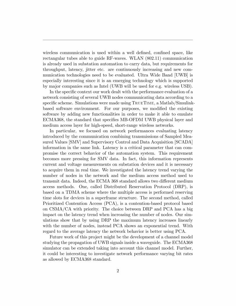
wireless communication is used within a well de�ned, con�ned space, likerectangular tubes able to guide RF-waves. WLAN (802.11) communicationis already used in substation automation to carry data, but requirements forthroughput, latency, jitter etc. are continuously increasing and new com-munication technologies need to be evaluated. Ultra Wide Band [UWB] isespecially interesting since it is an emerging technology which is supportedby major companies such as Intel (UWB will be used for e.g. wireless USB).In the speci�c context our work dealt with the performance evaluation of a
network consisting of several UWB nodes communicating data according to aspeci�c scheme. Simulations were made using TrueTime, a Matlab/Simulink-based software environment. For our purposes, we modi�ed the existingsoftware by adding new functionalities in order to make it able to emulateECMA368, the standard that speci�es MB-OFDM UWB physical layer andmedium access layer for high-speed, short-range wireless networks.In particular, we focused on network performances evaluating latency
introduced by the communication combining transmissions of Sampled Mea-sured Values [SMV] and Supervisory Control and Data Acquisition [SCADA]information in the same link. Latency is a critical parameter that can com-promise the correct behavior of the automation system. This requirementbecomes more pressing for SMV data. In fact, this information representscurrent and voltage measurements on substation devices and it is necessaryto acquire them in real time. We investigated the latency trend varying thenumber of nodes in the network and the medium access method used totransmit data. Indeed, the ECMA 368 standard allows two di¤erent mediumaccess methods. One, called Distributed Reservation Protocol (DRP), isbased on a TDMA scheme where the multiple access is performed reservingtime slots for devices in a superframe structure. The second method, calledPrioritized Contention Access (PCA), is a contention-based protocol basedon CSMA/CA with priority. The choice between DRP and PCA has a bigimpact on the latency trend when increasing the number of nodes. Our sim-ulations show that by using DRP the maximum latency increases linearlywith the number of nodes, instead PCA shows an exponential trend. Withregard to the average latency the network behavior is better using PCA.Future work of this project might be the development of a channel model
studying the propagation of UWB signals inside a waveguide. The ECMA368simulator can be extended taking into account this channel model. Further,it could be interesting to investigate network performance varying bit ratesas allowed by ECMA368 standard.
2
1.1. OUTLINE OF THE THESIS
1.1 Outline Of The Thesis
The contents of the thesis are as follows:
� Chapter 2: Substation Automation systems based on IEC61850.This chapter will introduce electrical substations and its automationsystems that represents the scenario of our thesis work. First, a briefoverview of electrical substations will be given. Then, substation au-tomation systems and the IEC 61850, an international standard de-signed to support the communication of all functions being performedin the substation, will be described.
� Chapter 3: Ultra-Wideband Technology. This chapter presentsa description of UWB. This emerging technology is having a rapiddevelopment and it is exciting interest of electronics technology majorssuch as Intel, Samsung, Philips, etc. Principal features and state of artof UWB will be shown. In particular the ECMA 368 standard whichde�nes the UWB PHY layer and the MAC sublayer will be described.
� Chapter 4: IEC61850 on ECMA368. Today, IEC61850 resortsto the utilization of Ethernet architectures for intercommunication. Inthis chapter it will be shown that UWB technology could be used in-stead of Ethernet in order to satisfy requirements dictated by IEC 61850applications.
� Chapter 5: TrueTime: A Matlab/Simulink �based simulator.This chapter presents a description of UWB. This emerging technologyis having a rapid development and it is exciting interest of electron-ics technology majors such as Intel, Samsung, Philips, etc. Principalfeatures and state of art of UWB will be shown. In particular will bedescribed ECMA 368 standard, on which several future applicationslike Wireless USB or Wireless FireWire will be based.
� Chapter 6: TrueTime extension. This chapter contains some newutilities implemented to improve the behavior and the usability of thewireless network block of TrueTime. In particular new C++ functioncodes and already existing modi�ed functions will be described. We alsoshow how SMV and SCADA data transmission has been emulated.
3
1.1. OUTLINE OF THE THESIS
� Chapter 7: Simulation setup. This chapter explains how the sim-ulator has been used in order to evaluate the behaviour of the UWBnetwork. In particular the signi�cant parameters for the investigationof an optimal con�guration are analyzed.
� Chapter 8: Simulation results. This chapter shows and analyzesresults obtained from simulations, evaluating the test-cases discussed insimulation setups. In particular, network performance are investigatedrespect to latency.
� Chapter 9: Conclusions. The last chapter presents the conclusionsof this thesis work. Some future work is also discussed.
4
Chapter 2
Substation automation systemsbased on IEC61850
2.1 Electrical substation overview
An electrical substation is a system involved in electricity generation,transmission and distribution networks where voltage is transformed fromhigh to low or the reverse. It uses step-up transformers for increasing voltageand decreasing current and step-down transformers for decreasing voltage andincreasing current for domestic and commercial distribution. In addition totransformers, an electrical substation contains equipment for switching, pro-tection and control. There are circuit breakers for protection from damagescaused by overload or short circuits, isolators capable of dealing with smallcharging currents of busbars and connection, conductor systems, insulationand overhead line terminations[1]. Substations may be located undergroundor on the surface, properly fenced and grounded. High-rise buildings mayhave indoor substations. Indoor substations are usually found in urban ar-eas to reduce the noise from the transformers, or to protect switchgear fromextreme climate or pollution. Protection of equipments become necessary toavoid failures, lightning strikes, power disturbances and accidents. Thus, thesubstations should be properly controlled and monitored in order to take thenecessary precautions accurately and timely. Controlling and monitoring op-erations are performed by a reliable and self healing system called SubstationAutomation (SA).
5
2.1. ELECTRICAL SUBSTATION OVERVIEW
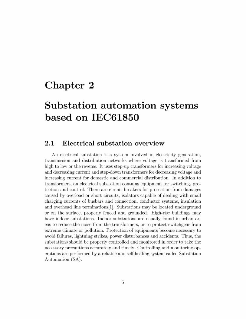
Figure 2.1.1: Example of an outdoor electrical substation
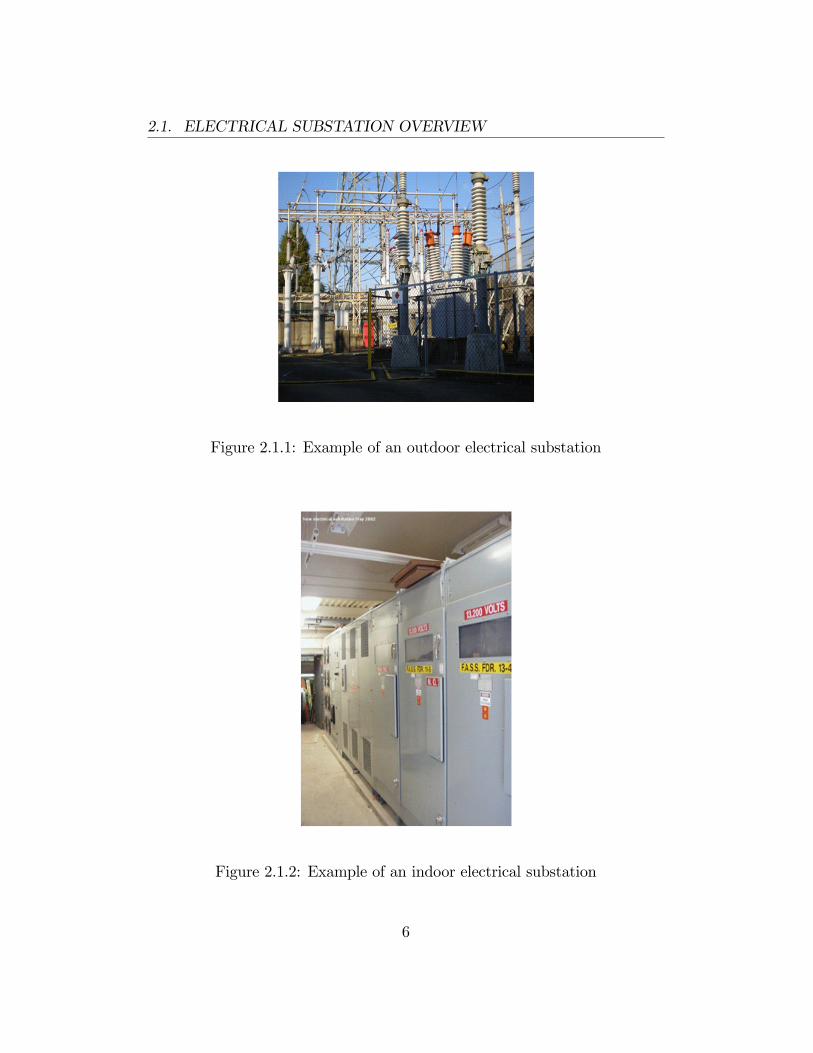
Figure 2.1.2: Example of an indoor electrical substation
6
2.2. SUBSTATION AUTOMATION SYSTEMS (SAS)
2.2 Substation Automation systems (SAS)
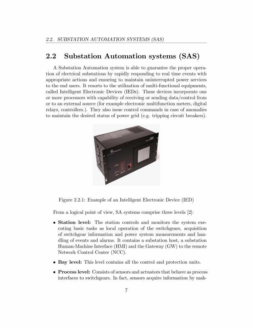
A Substation Automation system is able to guarantee the proper opera-tion of electrical substations by rapidly responding to real time events withappropriate actions and ensuring to maintain uninterrupted power servicesto the end users. It resorts to the utilization of multi-functional equipments,called Intelligent Electronic Devices (IEDs). These devices incorporate oneor more processors with capability of receiving or sending data/control fromor to an external source (for example electronic multifunction meters, digitalrelays, controllers.). They also issue control commands in case of anomaliesto maintain the desired status of power grid (e.g. tripping circuit breakers).
Figure 2.2.1: Example of an Intelligent Electronic Device (IED)
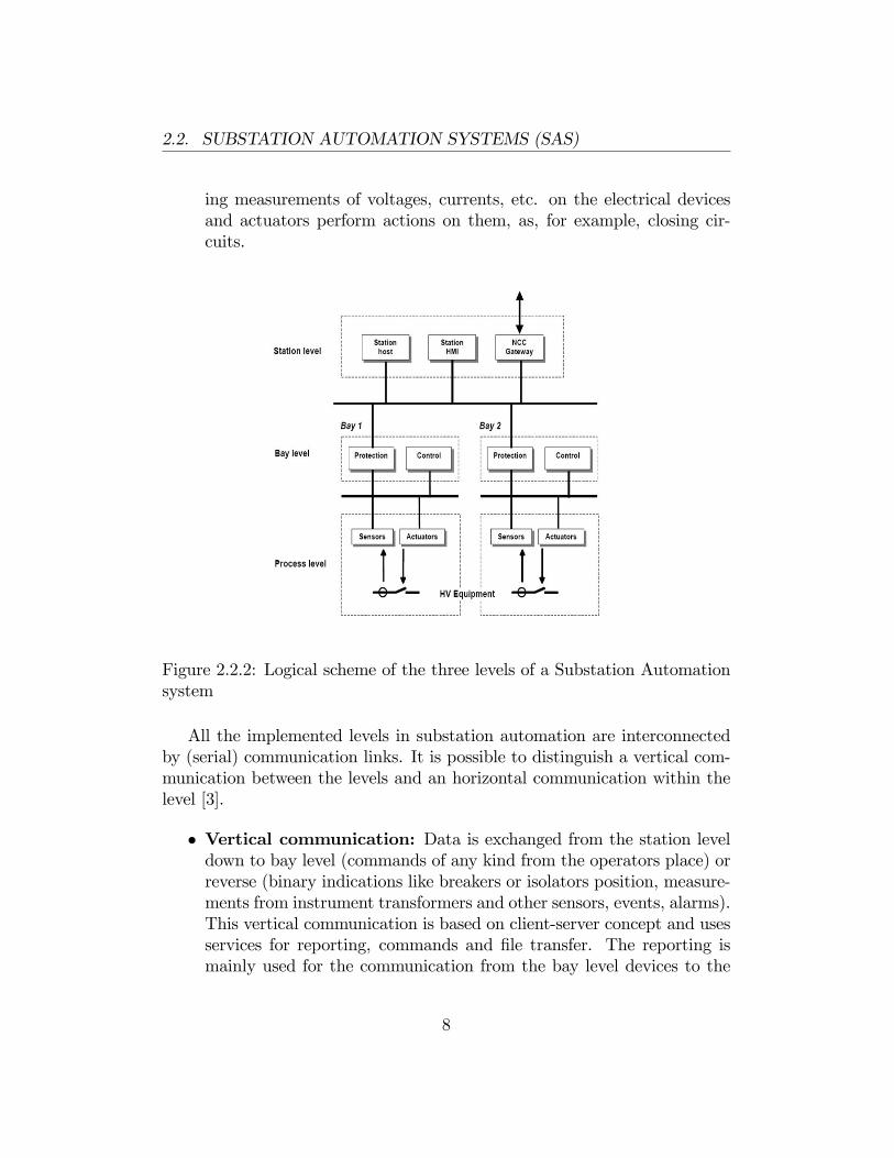
From a logical point of view, SA systems comprise three levels [2]:
� Station level: The station controls and monitors the system exe-cuting basic tasks as local operation of the switchgears, acquisitionof switchgear information and power system measurements and han-dling of events and alarms. It contains a substation host, a substationHuman-Machine Interface (HMI) and the Gateway (GW) to the remoteNetwork Control Center (NCC).
� Bay level: This level contains all the control and protection units.
� Process level: Consists of sensors and actuators that behave as processinterfaces to switchgears. In fact, sensors acquire information by mak-
7
2.2. SUBSTATION AUTOMATION SYSTEMS (SAS)
ing measurements of voltages, currents, etc. on the electrical devicesand actuators perform actions on them, as, for example, closing cir-cuits.
Figure 2.2.2: Logical scheme of the three levels of a Substation Automationsystem
All the implemented levels in substation automation are interconnectedby (serial) communication links. It is possible to distinguish a vertical com-munication between the levels and an horizontal communication within thelevel [3].
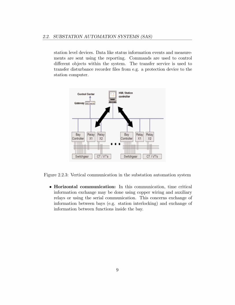
� Vertical communication: Data is exchanged from the station leveldown to bay level (commands of any kind from the operators place) orreverse (binary indications like breakers or isolators position, measure-ments from instrument transformers and other sensors, events, alarms).This vertical communication is based on client-server concept and usesservices for reporting, commands and �le transfer. The reporting ismainly used for the communication from the bay level devices to the
8
2.2. SUBSTATION AUTOMATION SYSTEMS (SAS)
station level devices. Data like status information events and measure-ments are sent using the reporting. Commands are used to controldi¤erent objects within the system. The transfer service is used totransfer disturbance recorder �les from e.g. a protection device to thestation computer.
Figure 2.2.3: Vertical communication in the substation automation system
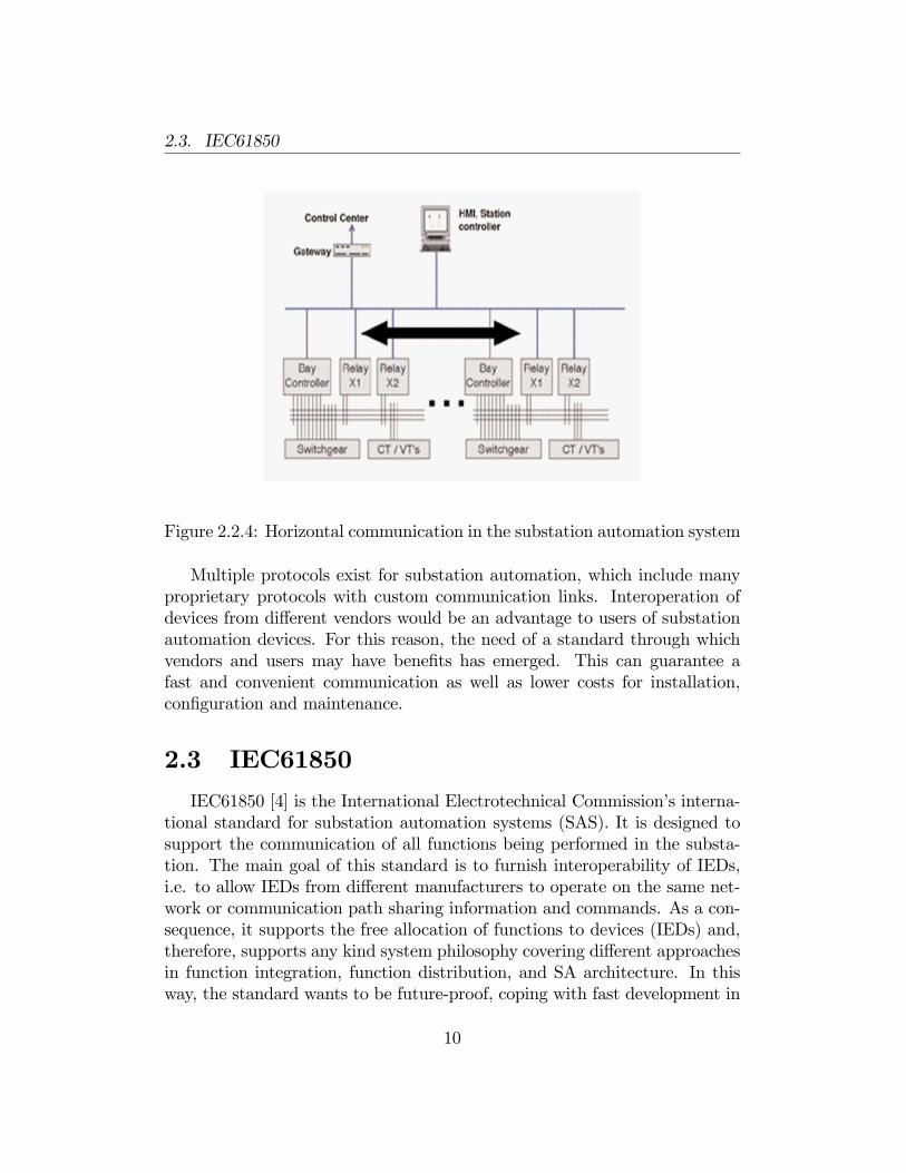
� Horizontal communication: In this communication, time criticalinformation exchange may be done using copper wiring and auxiliaryrelays or using the serial communication. This concerns exchange ofinformation between bays (e.g. station interlocking) and exchange ofinformation between functions inside the bay.
9
2.3. IEC61850
Figure 2.2.4: Horizontal communication in the substation automation system
Multiple protocols exist for substation automation, which include manyproprietary protocols with custom communication links. Interoperation ofdevices from di¤erent vendors would be an advantage to users of substationautomation devices. For this reason, the need of a standard through whichvendors and users may have bene�ts has emerged. This can guarantee afast and convenient communication as well as lower costs for installation,con�guration and maintenance.
2.3 IEC61850
IEC61850 [4] is the International Electrotechnical Commission�s interna-tional standard for substation automation systems (SAS). It is designed tosupport the communication of all functions being performed in the substa-tion. The main goal of this standard is to furnish interoperability of IEDs,i.e. to allow IEDs from di¤erent manufacturers to operate on the same net-work or communication path sharing information and commands. As a con-sequence, it supports the free allocation of functions to devices (IEDs) and,therefore, supports any kind system philosophy covering di¤erent approachesin function integration, function distribution, and SA architecture. In thisway, the standard wants to be future-proof, coping with fast development in
10
2.3. IEC61850
communication technology in the slow evolving application domain of powersystems.In the next paragraphs the architectures used for communication inside
SA, the data modeling approach and the data exchange model will be in-troduced, and typical applications for control or time-critical informationexchange will be described.
2.3.1 Communication architectures
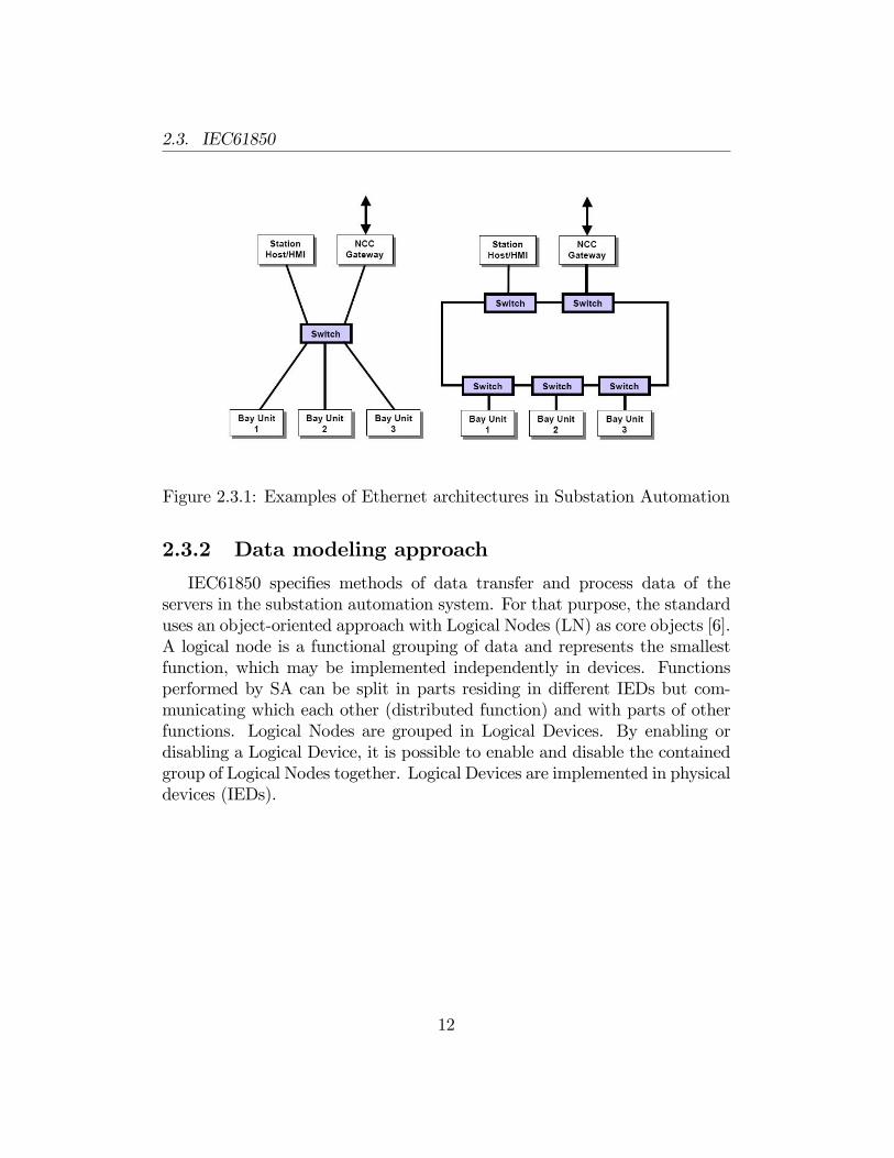
IEC61850 bases its communication architectures on Ethernet [5]. This isthe prevalent communication technology used in distribution automation dueto its cost savings and good functionality and performance. The standardo¤ers much �exibility in the choice of topologies and cabling. It supports dif-ferent communication architectures as, for example, cascading ,ring or star,commonly implemented with Ethernet switches with priority tagging. Thechoice of the architecture depends on the application performed on the sub-station and it is dictated by speci�c performance requirements. For example,IEC61850 requires that samples from the di¤erent sources should be takenin synchronism. Synchronization is presently implemented using a dedicatedsynchronisation network distributing a one pulse per second signal or usingspeci�c protocols as IEEE 1588 [or SNTP]. For time synchronization, jitter inthe switch is also important. For long sequences of switches like in ring con�g-urations, the delay per switch will contribute to the response time. Latencyrepresents another fundamental prerequisite, that may be lower to guaranteethe good working of the system. This is further discussed in Chapter 5.
11
2.3. IEC61850
Figure 2.3.1: Examples of Ethernet architectures in Substation Automation
2.3.2 Data modeling approach
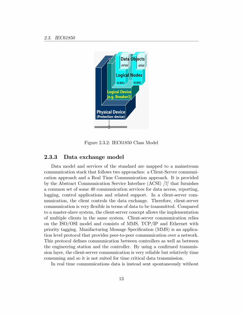
IEC61850 speci�es methods of data transfer and process data of theservers in the substation automation system. For that purpose, the standarduses an object-oriented approach with Logical Nodes (LN) as core objects [6].A logical node is a functional grouping of data and represents the smallestfunction, which may be implemented independently in devices. Functionsperformed by SA can be split in parts residing in di¤erent IEDs but com-municating which each other (distributed function) and with parts of otherfunctions. Logical Nodes are grouped in Logical Devices. By enabling ordisabling a Logical Device, it is possible to enable and disable the containedgroup of Logical Nodes together. Logical Devices are implemented in physicaldevices (IEDs).
12
2.3. IEC61850
Figure 2.3.2: IEC61850 Class Model
2.3.3 Data exchange model
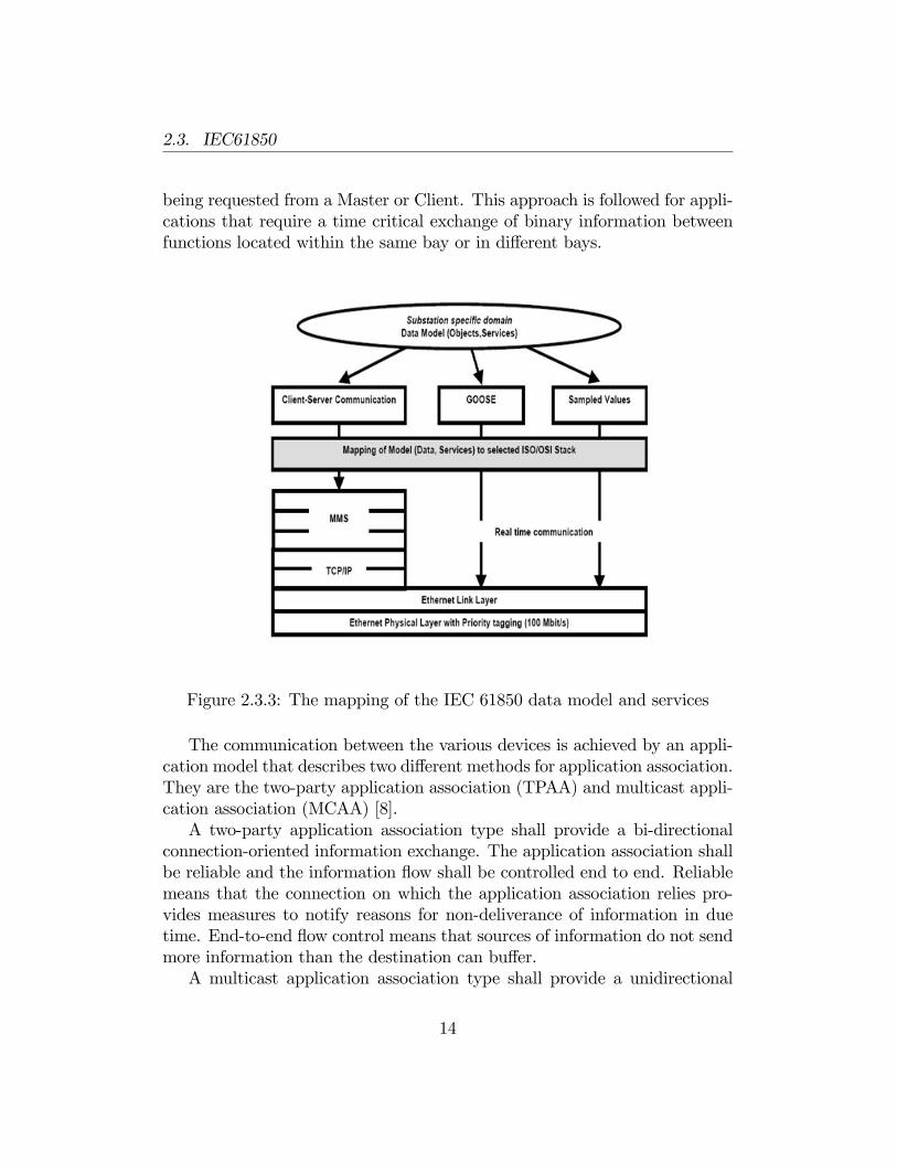
Data model and services of the standard are mapped to a mainstreamcommunication stack that follows two approaches: a Client-Server communi-cation approach and a Real Time Communication approach. It is providedby the Abstract Communication Service Interface (ACSI) [7] that furnishesa common set of some 40 communication services for data access, reporting,logging, control applications and related support. In a client-server com-munication, the client controls the data exchange. Therefore, client-servercommunication is very �exible in terms of data to be transmitted. Comparedto a master-slave system, the client-server concept allows the implementationof multiple clients in the same system. Client-server communication relieson the ISO/OSI model and consists of MMS, TCP/IP and Ethernet withpriority tagging. Manifacturing Message Speci�cation (MMS) is an applica-tion level protocol that provides peer-to-peer communication over a network.This protocol de�nes communication between controllers as well as betweenthe engineering station and the controller. By using a con�rmed transmis-sion layer, the client-server communication is very reliable but relatively timeconsuming and so it is not suited for time critical data transmission.In real time communications data is instead sent spontaneously without
13
2.3. IEC61850
being requested from a Master or Client. This approach is followed for appli-cations that require a time critical exchange of binary information betweenfunctions located within the same bay or in di¤erent bays.
Figure 2.3.3: The mapping of the IEC 61850 data model and services
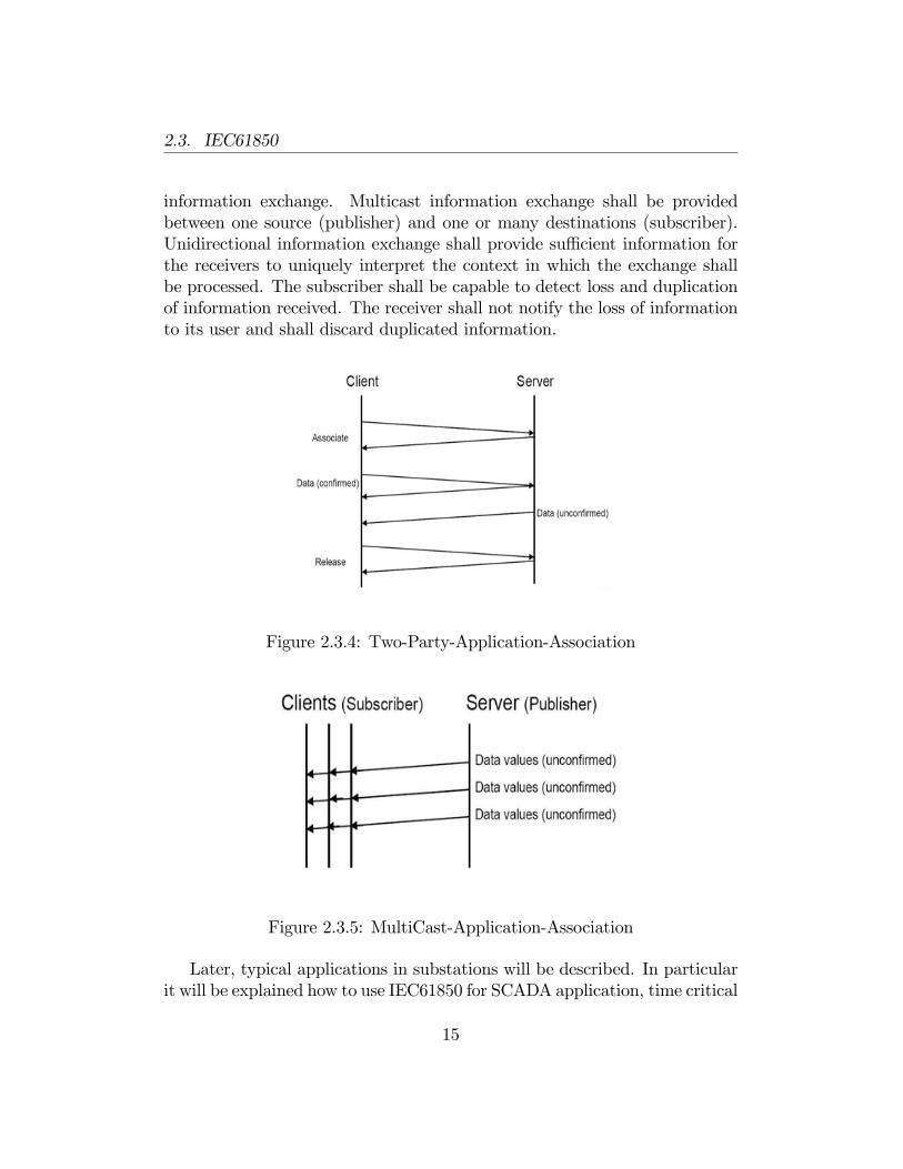
The communication between the various devices is achieved by an appli-cation model that describes two di¤erent methods for application association.They are the two-party application association (TPAA) and multicast appli-cation association (MCAA) [8].A two-party application association type shall provide a bi-directional
connection-oriented information exchange. The application association shallbe reliable and the information �ow shall be controlled end to end. Reliablemeans that the connection on which the application association relies pro-vides measures to notify reasons for non-deliverance of information in duetime. End-to-end �ow control means that sources of information do not sendmore information than the destination can bu¤er.A multicast application association type shall provide a unidirectional
14
2.3. IEC61850
information exchange. Multicast information exchange shall be providedbetween one source (publisher) and one or many destinations (subscriber).Unidirectional information exchange shall provide su¢ cient information forthe receivers to uniquely interpret the context in which the exchange shallbe processed. The subscriber shall be capable to detect loss and duplicationof information received. The receiver shall not notify the loss of informationto its user and shall discard duplicated information.
Figure 2.3.4: Two-Party-Application-Association
Figure 2.3.5: MultiCast-Application-Association
Later, typical applications in substations will be described. In particularit will be explained how to use IEC61850 for SCADA application, time critical
15
2.3. IEC61850
information exchange and connection of the primary process [10]. For thelast two applications the standard provides exchange services called GenericObject Oriented Substation Event (GOOSE) and Sampled Measured Values(SMV).
2.3.4 SCADA Application
Supervisory Control and Data Acquisition (SCADA) is one of the basictasks of a substation automation system. It is related to human operationof the network. Acquisition of information from high voltage equipment,handling of events and alarms are performed by a local or remote operator.The data communication for this application is directed vertically from higherto lower levels or reverse. For this vertical relationship IEC61850 uses theclient-server concept. The server is the process or bay level IED, whichprovides all data to the client at station or any remote level. The client istipically a computer representing the operator�s work place. This approachis well suited for SCADA information, that is not time critical. A typicalapplication of SCADA is creation of alarm lists and event lists. For thatpurpose, IEC61850 de�nes a report service that is not accessing individualdata, but group of data called datasets. Reports are sent to clients whenan event on the system occurs. An event causing a transmission may bea change of a binary value, the crossing of a prede�ned alarm limit or theexpiration of a cycle time.
2.3.5 Generic Object Oriented Substation Event (GOOSE)
IEC61850 introduces a speci�c information exchange service for time criti-cal exchange of binary information between functions located within the samebay or in di¤erent bays, called Generic Object Oriented Substation Event(GOOSE) [8]. It is based on the publisher-subscriber concept and it is usedfor fast transmission of substation events, such as commands, alarms and in-dications. Messages are sent as multicast messages over the communicationnetwork and they are uncon�rmed. The publisher has no way of knowingif the subscriber has received the message. Because of this, the publishermust continuously transmit messages to the LAN. The triggering event forGOOSE messages may be a change of a value, a crossing of a boundary,etc. The content of messages is de�ned with a dataset (similar like for thereport model). Typical applications that resort to the utilization of GOOSE
16
2.3. IEC61850
service are exchange of information between devices inside the bay or be-tween devices placed in di¤erent bays. An example of the �rst case is thecommunication between a logical device that control the distance protectionand a logical device recloser that will send an open command to the breaker.Breaker failure protection is an example of communication between bays.
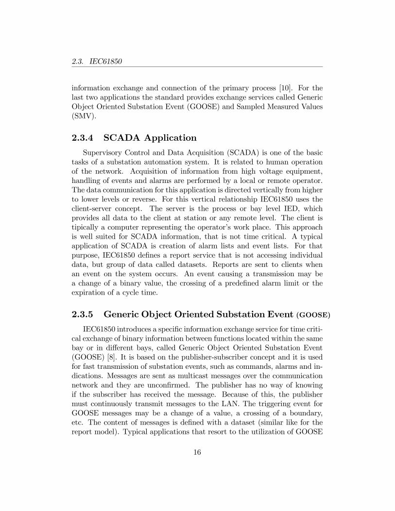
Figure 2.3.6: Example of GOOSE transmission
2.3.6 Sampled Measured Values (SMV) transmission
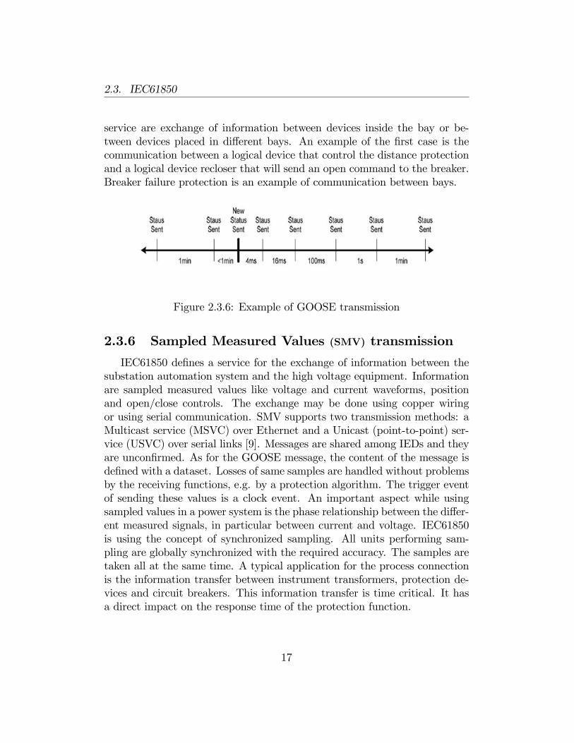
IEC61850 de�nes a service for the exchange of information between thesubstation automation system and the high voltage equipment. Informationare sampled measured values like voltage and current waveforms, positionand open/close controls. The exchange may be done using copper wiringor using serial communication. SMV supports two transmission methods: aMulticast service (MSVC) over Ethernet and a Unicast (point-to-point) ser-vice (USVC) over serial links [9]. Messages are shared among IEDs and theyare uncon�rmed. As for the GOOSE message, the content of the message isde�ned with a dataset. Losses of same samples are handled without problemsby the receiving functions, e.g. by a protection algorithm. The trigger eventof sending these values is a clock event. An important aspect while usingsampled values in a power system is the phase relationship between the di¤er-ent measured signals, in particular between current and voltage. IEC61850is using the concept of synchronized sampling. All units performing sam-pling are globally synchronized with the required accuracy. The samples aretaken all at the same time. A typical application for the process connectionis the information transfer between instrument transformers, protection de-vices and circuit breakers. This information transfer is time critical. It hasa direct impact on the response time of the protection function.
17
2.3. IEC61850
Figure 2.3.7: Process connection with serial communication for SMV trans-mission
18
Chapter 3
Ultra-Wideband Technology
This chapter will introduce Ultra-Wideband (UWB), a wireless communi-cation technology designed for short-range, personal area networks, or PANs.It is rapidly gaining interest of researchers and its concept spans many dif-ferent applications and industries.
3.1 UWB description
A signal has been de�ned from the Federal Communication Commission(FCC) as UWB when its fractional bandwidth (that is de�ned as the ratioof the signal bandwidth to the center frequency) is greater than 0.25 or itoccupies 1.5 GHz or more of spectrum. In February 2002, the FCC allocated7500MHz spectrum [13], from 3.1 to 10.6GHz, for unlicensed UWB commu-nication applications thus allowing the use and the commercialization of newproducts that use this technology.The UWB technology can be used in many applications, for example
imaging systems, vehicular radar systems, communication and measurementsystems. [14]The combination of a big bandwidth and a relatively low centre frequency
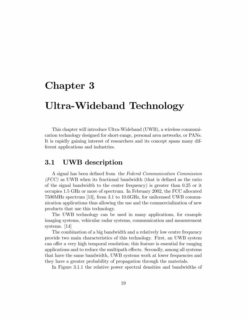
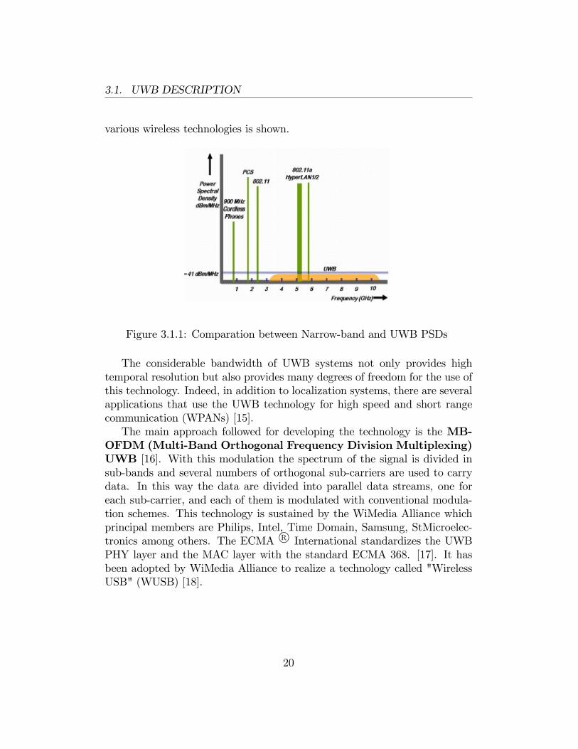
provide two main characteristics of this technology. First, an UWB systemcan o¤er a very high temporal resolution; this feature is essential for rangingapplications and to reduce the multipath e¤ects. Secondly, among all systemsthat have the same bandwidth, UWB systems work at lower frequencies andthey have a greater probability of propagation through the materials.In Figure 3.1.1 the relative power spectral densities and bandwidths of
19
3.1. UWB DESCRIPTION
various wireless technologies is shown.
Figure 3.1.1: Comparation between Narrow-band and UWB PSDs
The considerable bandwidth of UWB systems not only provides hightemporal resolution but also provides many degrees of freedom for the use ofthis technology. Indeed, in addition to localization systems, there are severalapplications that use the UWB technology for high speed and short rangecommunication (WPANs) [15].The main approach followed for developing the technology is the MB-
OFDM (Multi-Band Orthogonal Frequency Division Multiplexing)UWB [16]. With this modulation the spectrum of the signal is divided insub-bands and several numbers of orthogonal sub-carriers are used to carrydata. In this way the data are divided into parallel data streams, one foreach sub-carrier, and each of them is modulated with conventional modula-tion schemes. This technology is sustained by the WiMedia Alliance whichprincipal members are Philips, Intel, Time Domain, Samsung, StMicroelec-tronics among others. The ECMA R International standardizes the UWBPHY layer and the MAC layer with the standard ECMA 368. [17]. It hasbeen adopted by WiMedia Alliance to realize a technology called "WirelessUSB" (WUSB) [18].
20
3.2. ECMA 368
3.2 ECMA 368
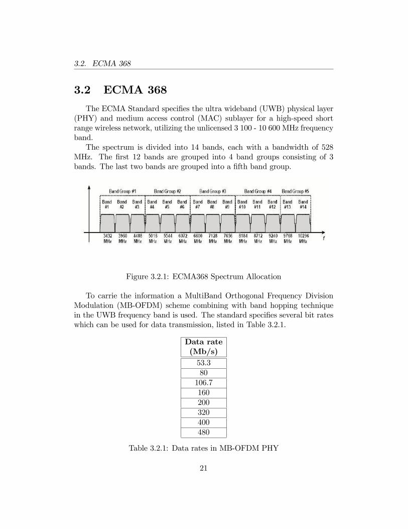
The ECMA Standard speci�es the ultra wideband (UWB) physical layer(PHY) and medium access control (MAC) sublayer for a high-speed shortrange wireless network, utilizing the unlicensed 3 100 - 10 600 MHz frequencyband.The spectrum is divided into 14 bands, each with a bandwidth of 528
MHz. The �rst 12 bands are grouped into 4 band groups consisting of 3bands. The last two bands are grouped into a �fth band group.
Figure 3.2.1: ECMA368 Spectrum Allocation
To carrie the information a MultiBand Orthogonal Frequency DivisionModulation (MB-OFDM) scheme combining with band hopping techniquein the UWB frequency band is used. The standard speci�es several bit rateswhich can be used for data transmission, listed in Table 3.2.1.
Data rate(Mb/s)53.380106.7160200320400480
Table 3.2.1: Data rates in MB-OFDM PHY
21
3.2. ECMA 368
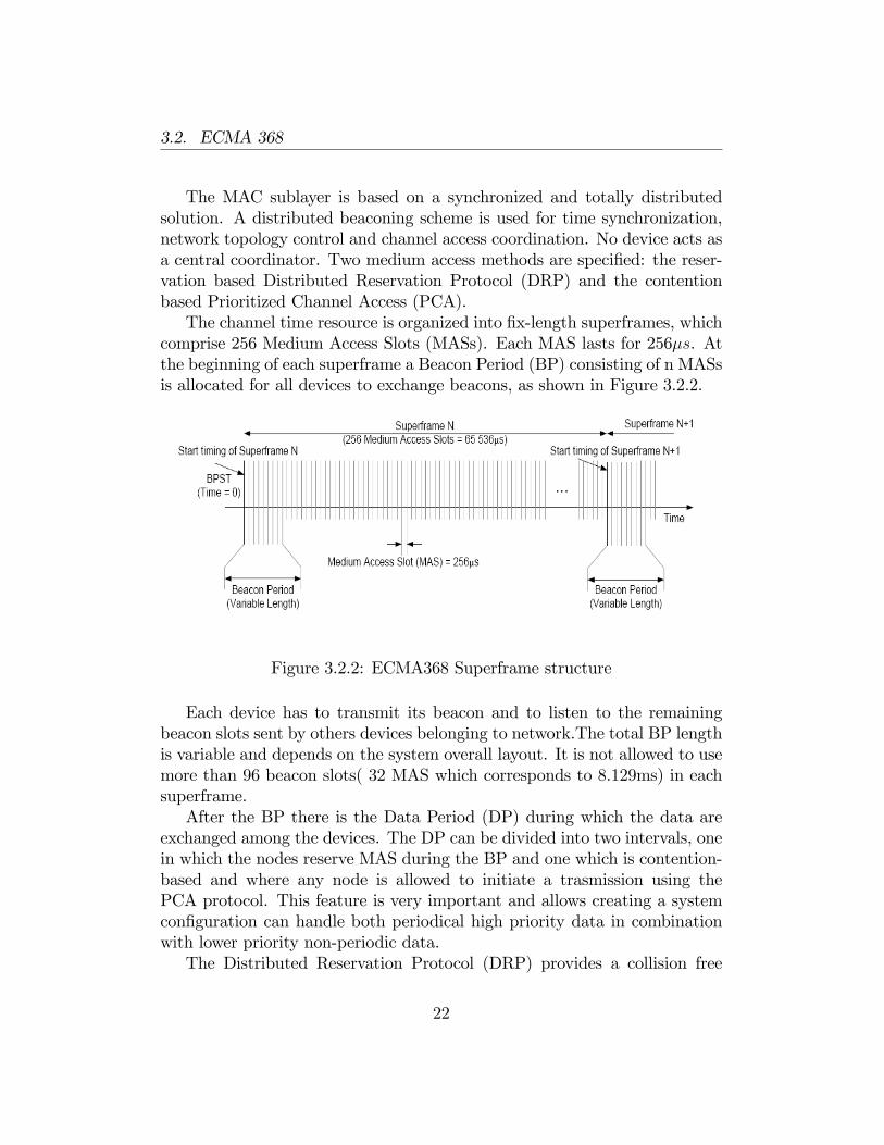
The MAC sublayer is based on a synchronized and totally distributedsolution. A distributed beaconing scheme is used for time synchronization,network topology control and channel access coordination. No device acts asa central coordinator. Two medium access methods are speci�ed: the reser-vation based Distributed Reservation Protocol (DRP) and the contentionbased Prioritized Channel Access (PCA).The channel time resource is organized into �x-length superframes, which
comprise 256 Medium Access Slots (MASs). Each MAS lasts for 256�s. Atthe beginning of each superframe a Beacon Period (BP) consisting of n MASsis allocated for all devices to exchange beacons, as shown in Figure 3.2.2.
Figure 3.2.2: ECMA368 Superframe structure
Each device has to transmit its beacon and to listen to the remainingbeacon slots sent by others devices belonging to network.The total BP lengthis variable and depends on the system overall layout. It is not allowed to usemore than 96 beacon slots( 32 MAS which corresponds to 8.129ms) in eachsuperframe.After the BP there is the Data Period (DP) during which the data are
exchanged among the devices. The DP can be divided into two intervals, onein which the nodes reserve MAS during the BP and one which is contention-based and where any node is allowed to initiate a trasmission using thePCA protocol. This feature is very important and allows creating a systemcon�guration can handle both periodical high priority data in combinationwith lower priority non-periodic data.The Distributed Reservation Protocol (DRP) provides a collision free
22
3.2. ECMA 368
channel access. It announces future transmissions and thus allows devicesto coordinate their channel access.Through beaconing, devices sharing the same BP can learn the MAS
occupation status and make their own reservation. The reservation is an-nounced by the owner device in its beacon and identi�ed with the start MASnumber and the duration in unit of MASs.There are several levels on which the reservation can be made according
to ECMA 368. In particular an exclusive access to the medium can be pro-vided for the reservation owner and target (hard reservation) or a preferentialaccess is given to the reservation owner permitting PCA in the MAS (softreservation).The PCA is very similar to the Enhanced Distributed Channel Access
(EDCA) [19]. It is a contention-based Carrier Sense Multiple Access/CollisionAvoidance (CSMA/CA) scheme relying on a prioritized backo¤ procedure.Virtual stations of di¤erent priority inside every device compete for the chan-nel access. The standard ECMA 368 allows four Access Categories (AC),each of them has a di¤erent priority.Prior to every transmission attempt a device has to sense the channel
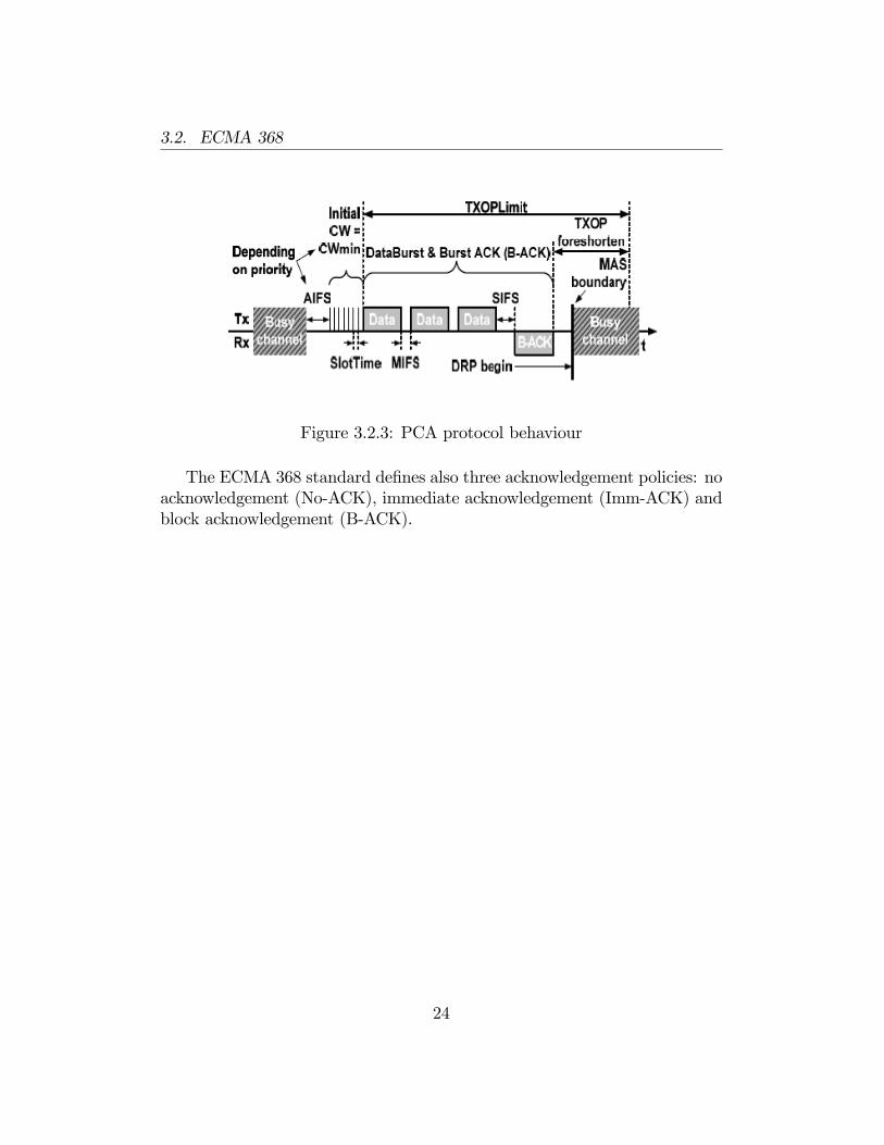
as idle for a static period called Arbitration Interframe Space (AIFS). Af-terwards, it has to keep on sensing the channel for multiples of a SlotTime.For the current MBOA PHY the SlotTime is equal to 8 �s. The amount ofSlotTimes is a random number drawn from a uniformly distributed intervalof (0, CW). The initial value of CW is CWmin. The duration of AIFS andCWmin depend on the priority of the backo¤. Whenever the device sensesthe channel as idle it decreases its slot counter by one. If the slot counterreaches zero the device may transmit a data packet. If the device senses thechannel as busy, it freezes its slot counter. After the channel is sensed as idlefor an AIFS period again, the backo¤ procedure starts counting down theremaining slots. With every failed transmission a device doubles it CW toreduce the probability of a collision with other devices [20].As an example, a PCA based channel access sequence is depicted in Figure
3.2.3.
23
3.2. ECMA 368
Figure 3.2.3: PCA protocol behaviour
The ECMA 368 standard de�nes also three acknowledgement policies: noacknowledgement (No-ACK), immediate acknowledgement (Imm-ACK) andblock acknowledgement (B-ACK).
24
Chapter 4
IEC61850 on ECMA 368
The IEC61850 standard for Substation Automation resorts to the uti-lization of the Ethernet technology for intercommunication, as mentionedin chapter 2. Many applications have requirements regarding time synchro-nization, low levels of latency and jitter, which switched Ethernet is able tomeet. For medium voltage applications optical Ethernet is used to ensuregalvanic isolation between di¤erent units in an installation. However, thisusage is both expensive and fragile and good alternatives are now in courseof study. One of them is the usage of a waveguide system for RF-waves inorder to reduce costs and installation e¤ort. The basic idea is to use rectan-gular tubes to transmit RF signals. In this way, RF-waves are guided andbasically free of disturbances. The choice of a wireless technology that canful�l the requirements of IEC61850 applications becomes fundamental. Anemerging technology that seems to have good performance is the MB-OFDMUWB based on standards ECMA368-369. It is having a rapid developmentand it is exciting interest of electronics technology majors as Intel, Samsung,Philips, etc. The high bandwidth (up to 480 Mb/s) permits the use of UWBin many applications, from multimedia to military communications.
4.1 ECMA368 for SMV transmission
In chapter 2 the Sampled Measured Values service has been described. Itis a method for transmitting sampled measurements from transducers. Formedium voltage applications each device typically produces a sample of 256bytes every 250 �s:The main requirements on this kind of communication
25
4.1. ECMA368 FOR SMV TRANSMISSION
regard time-synchronization, latency, bandwidth and sampling interval. Inparticular they are:
� Time-synchronization of <25 �s
� Latency of <3 ms
� Bandwidth >10 Mbit/s
� Sampling interval >4kHz (allowed to bundle data as long as latencyrequirements are met)
Transmission of SMV data might be performed using the DistributedReservation Protocol (DRP), where nodes have access to the medium in re-served slots, or the Prioritized contention access (PCA), that provides di¤er-entiated, distributed contention access to the medium. In SMV applicationsthe higher layers don�t allow acknowledgement policies but ECMA 368 stan-dard o¤ers di¤erent ack methods at the MAC layer. Later on, main aspectsof the two protocols and some theoretical considerations about their use inorder to satisfy application requirements will be described.
4.1.1 Time Synchronization
ECMA368 standard o¤ers support for higher-layer time synchronization,that is a fundamental requirement for SMV information in IEC61850 applica-tions. In fact, the phase relationship between the di¤erent measured signalsis fundamental and samples must be acquired at the same time. The stan-dard de�nes an optional MAC facility that enables layers above the MACsub layer to accurately synchronize timers located in di¤erent devices. First,a low-level synchronization can be achieved in order to ful�l the standard.The accuracy is de�ned as the maximum drift between synchronizations.
In the ECMA368 case it is function of the clock accuracy and the time elapsed(SynchronizationInterval) since a synchronization event. The maximum driftis calculated using the worst case value for clock accuracy and the longestSynchronizationInterval:
MaxDrift = mClockAccuracy (ppm) � 1E-6 � SynchronizationInterval(4.1.1)
26
4.1. ECMA368 FOR SMV TRANSMISSION
where
SynchronizationInterval = (mMaxLostBeacons + 1) �mSuperframeLengthmClockAccuracy = 20 ppmmMaxLostBeacons = 3
mSuperframeLength = 65536 �s(4.1.2)
This guarantees a MaxDrift =10,5 �s:This accuracy could not be the same at the higher-levels. Jitter in the
system (up to 3 ms) must be considered. A solution that can achieve highaccuracy synchronization is the use of a proxy device that synchronizes itstime with a global clock on the outside network using a SNTP or IEEE 1588protocol. The application in the proxy periodically transmits packets to othernodes in the network containing time information. It keeps track of the o¤setbetween a reserved MAS used to transmit the clock-synchronization and theglobal clock. The applications in the nodes can use information received byproxy to adjust its local clock to concur with the global clock. This strategymake it possible to get an o¤set <11 �s between the clock in the proxy andthe clocks in the other nodes.
4.1.2 SMV on Distributed Reservation Protocol (DRP)
SMV data can be transmitted by nodes in the network during the dataperiod in the ECMA 368 superframe. After the reservation accorded in theBeacon period, each node can have access to the medium in reserved slots.The standard describes several levels on which the reservation can be made,as mentioned in chapter 4. Hard reservation is suitable for nodes which needto transmit every time, while Soft reservation is useful for nodes that needto reserve periodical access to the medium to be used if an event occurs ora value changes. In particular, for SMV data, hard reservation has beenconsidered in this work. In order to ful�l latency requirements the numberof nodes in the network has a big impact.A typical con�guration in substation application consists in n nodes in
the segment; n� 1 SMV and SCADA-producing nodes and one proxy devicewhich communicates with the outside network. The choice of an appropriatenumber of transmitting nodes has e¤ect on the Beacon Period length. EachBP has a duration of a number of beacon slots (85�s) which is always a
27
4.2. ECMA368 FOR SCADA TRANSMISSION
multiple of three. Since each node needs a beacon slot for transmitting theirinformation, the length of BP is depending of the number of nodes. Inaddition, two signaling slots have to be considered. It is not allowed to usemore than 96 beacon slots (32 MAS which corresponds to 8,129ms) in eachsuperframe. Data period con�guration is also necessary in order to meetlatency requirements. A suitable con�guration is:
� Hard reservation for n�1 consecutive MAS (one for each SMV-producingnode)
� Leaves one MAS for PCA every n � 1 MAS, which can be used forSCADA tra¢ c
Since each MAS has a duration of 256 �s and considering one MAS foreach data-producing node, latency is function of the number of devices. Eachnode is enabled to transmit periodical data every NumberOfNodes�256�sexcept for once every superframe when the actual time between 2 consecutivetransmission opportunities will increase due to the beacon period.
4.1.3 SMV on Prioritized Contention Access (PCA)
Transmission of SMV data can be performed using the contention-basedprotocol furnished by ECMA 368 standard. Unlike DRP, nodes don�t trans-mit data in reserved MAS, but they have access to the medium dependingon their priority and following the algorithm described in chapter 4. Once anode has obtained access, it has a Transmission Opportunity (TXOP) , aninterval of time to initiate transmission onto the medium. Sampled valuesrepresent information with a high priority sent periodically. It is possible tocreate a system con�guration which can handle both SMV data in combina-tion with lower priority non-periodic data. They are supervisory control anddata acquisition (SCADA) information, that will be presented in the nextparagraph.
4.2 ECMA368 for SCADA transmission
SCADA information is not time-critical data that comprise local and re-mote operation of high voltage equipment. A typical con�guration providesfor transmission of 2 packets of 183 bytes every second on average. Since
28
4.2. ECMA368 FOR SCADA TRANSMISSION
control data is fundamental for a substation automation system, the presenceof an acknowledgement policy is requested. The station controller receivesdata packets from equipment in the bay and process level and resend ackpackets of 53 bytes with an average delay of 15ms. This is performed at theapplication layer. By using the ECMA368 standard for SCADA transmis-sion, it is also possible to consider ack policies at the MAC layer, distinguingbetween an Immediate ACK and a burst ACK (see chapter 4). PCA proto-col seems to be well suggested for this kind of transmission. In particular,two system con�gurations can be studied. SCADA packets might be trans-mitted in a superframe structure, leaving a MAS for PCA after a certainnumber of reserved MAS for SMV transmission or by using only PCA. Inthis case SCADA information compete for the access to the medium withperiodical high priority data and they are supplied with a low priority. Bothcon�gurations will be examined in chapter 7, where performances have beeninvestigated.
29
Chapter 5
TrueTime: aMatlab/Simulink-basedsimulator
In this chapter the simulation software environment, TrueTime, usedduring the thesis work will be introduced. It has been modi�ed and extendedin order to make it capable of emulating the behaviour of an UWB network.
5.1 Tool description
TrueTime [21] is a Matlab/Simulink-based simulator for real-time con-trol systems, developed at Lund University, in Sweden, since 1999. It facil-ities co-simulation of controller task execution in real-time kernels, networktransmissions and continuous plant dynamics by providing a Simulink blocklibrary and a collection of MATLAB MEX �les. TrueTime is not based onmathematical modeling formalism but simulations are programmed in a waysimilar to real embedded systems. The application is written in Matlab codeor in C++ and execution/transmission times must be speci�ed by the devel-oper. In the C++ case, functions are compiled using Matlab�s MEX facility,rendering a much faster simulation. This approach makes TrueTime a very�exible co-simulation tool. In the next paragraph the fundamentals Simulinkblocks furnished by the software will be described in details.
30
5.1. TOOL DESCRIPTION
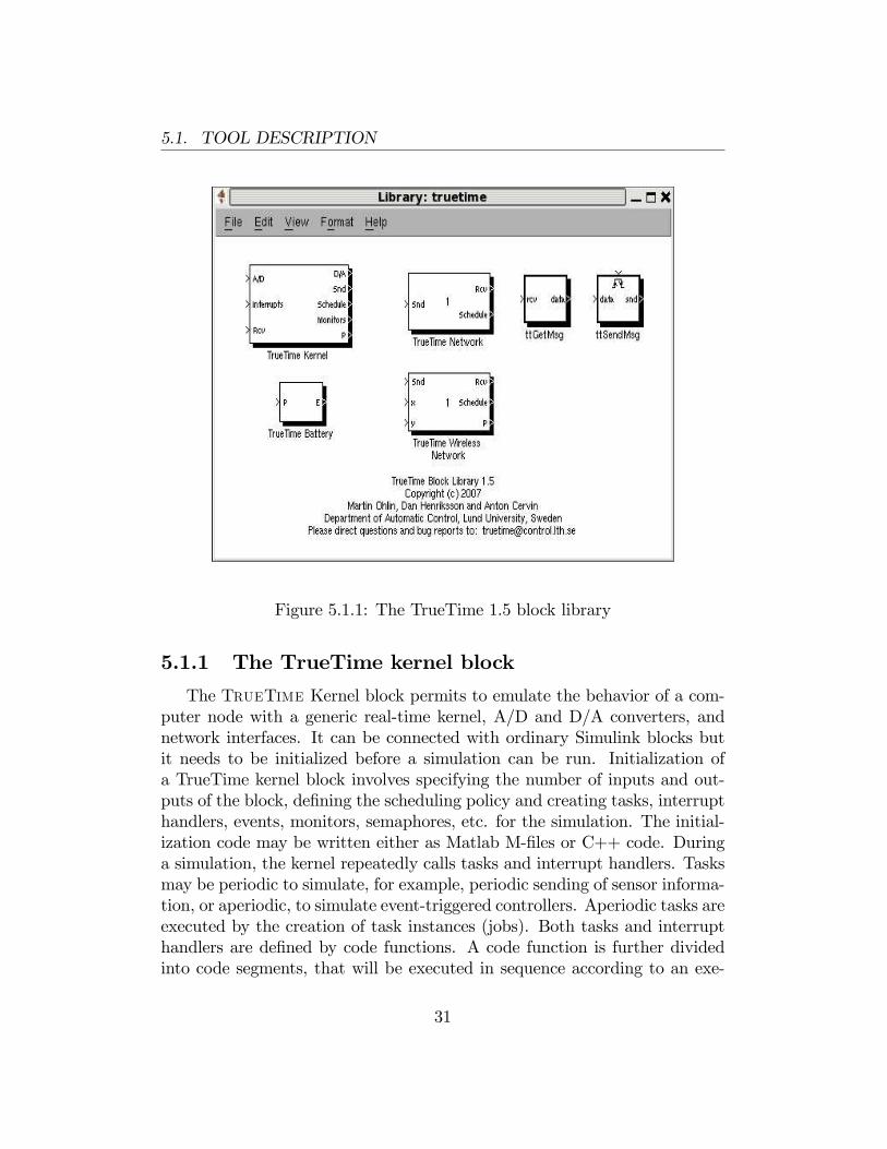
Figure 5.1.1: The TrueTime 1.5 block library
5.1.1 The TrueTime kernel block
The TrueTime Kernel block permits to emulate the behavior of a com-puter node with a generic real-time kernel, A/D and D/A converters, andnetwork interfaces. It can be connected with ordinary Simulink blocks butit needs to be initialized before a simulation can be run. Initialization ofa TrueTime kernel block involves specifying the number of inputs and out-puts of the block, de�ning the scheduling policy and creating tasks, interrupthandlers, events, monitors, semaphores, etc. for the simulation. The initial-ization code may be written either as Matlab M-�les or C++ code. Duringa simulation, the kernel repeatedly calls tasks and interrupt handlers. Tasksmay be periodic to simulate, for example, periodic sending of sensor informa-tion, or aperiodic, to simulate event-triggered controllers. Aperiodic tasks areexecuted by the creation of task instances (jobs). Both tasks and interrupthandlers are de�ned by code functions. A code function is further dividedinto code segments, that will be executed in sequence according to an exe-
31
5.1. TOOL DESCRIPTION
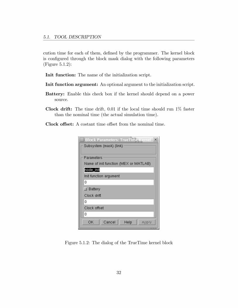
cution time for each of them, de�ned by the programmer. The kernel blockis con�gured through the block mask dialog with the following parameters(Figure 5.1.2):
Init function: The name of the initialization script.
Init function argument: An optional argument to the initialization script.
Battery: Enable this check box if the kernel should depend on a powersource.
Clock drift: The time drift, 0.01 if the local time should run 1% fasterthan the nominal time (the actual simulation time).
Clock o¤set: A costant time o¤set from the nominal time.
Figure 5.1.2: The dialog of the TrueTime kernel block
32
5.1. TOOL DESCRIPTION
5.1.2 The TrueTime wired network block
The Wired Network block permits to simulate the physical-layer and themedium access layer of various local-area networks. It supports six simplemodes of networks: CSMA/CD (e.g. Ethernet), CSMA/AMP (e.g CAN),Round Robin (e.g. Token Bus), FDMA, TDMA and Switched Ethernet.Higher protocols such as TCP/IP are not simulated (but may be imple-mented as applications in the nodes). When a node tries to transmit a mes-sage, a triggering signal is sent to the network block on the correspondinginput channel. When the simulated transmission of the message is �nished,the network block sends a new triggering signal on the output channel corre-sponding to the receiving node. The transmitted message is put in a bu¤erat the receiving computer node. A message contains information about thesending and the receiving computer node, arbitrary user data (typically mea-surement signals or control signals), the length of the message, and optionalreal-time attributes such as a priority or a deadline.The network block is con�gured through the block mask dialog (Figure
5.1.3).
33
5.1. TOOL DESCRIPTION
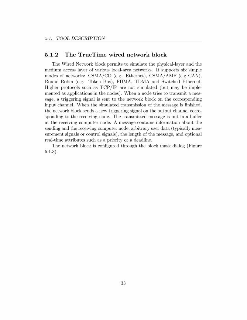
Figure 5.1.3: The dialog of the TrueTime network block
The following network parameters are common to all models:
Network number: The number of the network block. The networks mustbe numbered from 1 and upwards. Wired and wireless networks arenot allowed to use the same number.
Number of nodes: The number of nodes that are connected to the net-work.
34
5.1. TOOL DESCRIPTION
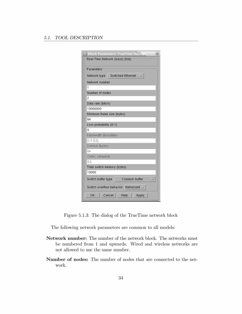
Data rate (bits/s): The speed of the network.
Minimum frame size (bits): A message frame shorter than this will bepadded to give the minimum length. Denotes the minimum frame size,including any overhead introduced by the protocol.
Pre-processing delay (s): The time a message is delayed by the networkinterface on the sending end. This can be used to model, e.g., a slowserial connection between the computer and the network interface.
Post-processing delay (s): The time a message is delayed by the networkinterface on the receiving end.
Loss probability (0-1): The probability that a network message is lostduring transmission. Lost messages will consume network bandwidth,but will never arrive at the destination.
5.1.3 The TrueTime wireless network block
The Wireless Network block works in the same way as the wired one andpermits to simulate communication between nodes taking also into accountthe path-loss of the radio signal. It is necessary to specify the true locationof the nodes with x and y inputs. Only two network protocols were sup-ported originally: IEEE 802.11b/g (WLAN) and IEEE 802.15.4 (WPAN).WirelessHART has been added in a recent work at ABB Corporate Researchwhile adding ECMA368 standard has been the purpose of our work.The radio model used includes support for:
� Ad-hoc wireless networks.
� Isotropic antenna.
� Inability to send and receive messages at the same time.
� Path loss of radio signals modeled as 1dawhere d is the distance in
meters and a is a parameter chosen to model the environment.
� Interference from other terminals.
35
5.1. TOOL DESCRIPTION
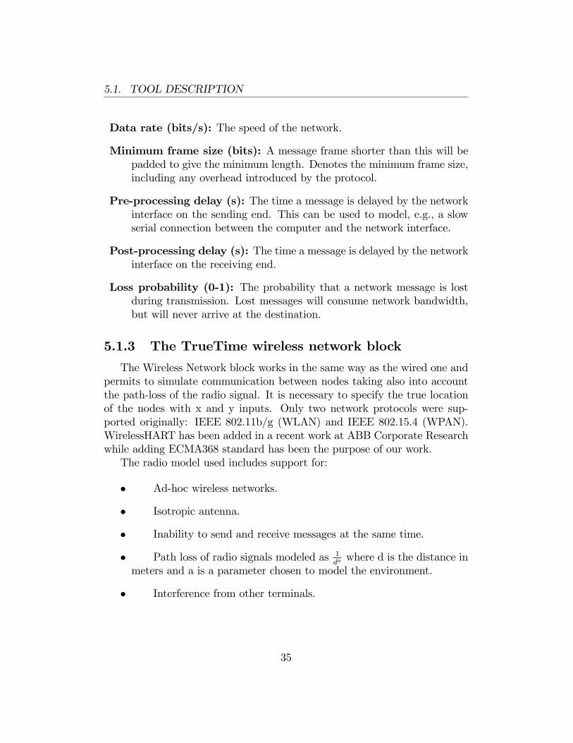
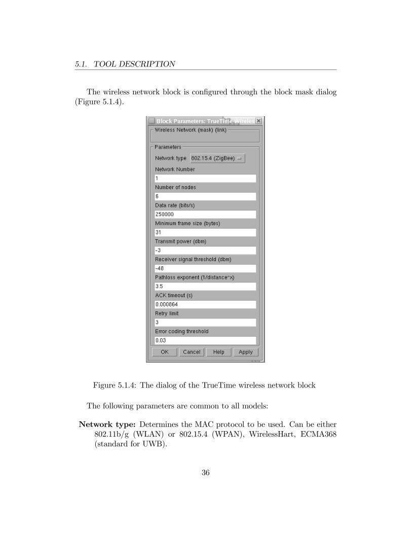
The wireless network block is con�gured through the block mask dialog(Figure 5.1.4).
Figure 5.1.4: The dialog of the TrueTime wireless network block
The following parameters are common to all models:
Network type: Determines the MAC protocol to be used. Can be either802.11b/g (WLAN) or 802.15.4 (WPAN), WirelessHart, ECMA368(standard for UWB).
36
5.1. TOOL DESCRIPTION
Network number: The number of the network block. The networks mustbe numbered from 1 to upwards. Wired and wireless networks are notallowed to use the same number.
Number of nodes: The number of nodes that are connected to the net-work. This number will determine the size of the Snd, Rcv and Scheduleinput and outputs of the block.
Data rate (bits/s): The speed of the network.
Minimum frame size (bits): A message frame shorter than this will bepadded to give the minimum length. Denotes the minimum frame size,including any overhead introduced by the protocol. E.g. most networkprotocols have a �xed number of header and tails bits, so frame mustbe at least sizeof(header) + sizeof(tail) long.
Transmit power: Determines how strong the radio signal will be, andthereby how long it will reach.
Receiver signal threshold: If the received energy is above this threshold,then the medium is accounted as busy.
Path-loss exponent: The path loss of the radio signal is modeled as 1da
where d is the distance in meters and a is a suitably chosen parameterto model the environment. Typically chosen in the interval 2-4.
ACK timeout: The time a sending node will wait for an ACK messagebefore concluding that the message was lost and retransmit it.
Retry limit: The maximum number of times a node will try to retransmita message before giving up.
Error coding threshold: A number in the interval [0,1] which de�nes thepercentage of block errors in a message that the coding can handle.For example, certain coding schemes can fully reconstruct a messageif it has less than 3% block errors. The number of block errors arecalculated using the signal-to-noise ratio, where the noise is all otherongoing transmissions.
The parameters for ECMA368 will be described in Chapter 6.
37
5.2. WIRELESS NETWORK BLOCK IMPLEMENTATION DETAILS
5.2 Wireless network block implementationdetails
In this paragraph the behavior of 802.11b/g (WLAN) and 802.15.4 (WPAN)protocols implemented in the Wireless network block will be described. Inaddition, we will show show how the simulator treats calculation of errorprobabilities and path-loss.
5.2.1 802.11b/g (WLAN)
IEEE 802.11b/g [11] is a standard for wireless local area network (WLAN)computer communication. Today It is used in many laptops and mobiledevices. The protocol is based on CSMA/CA with some modi�cations.In the simulation, a package transmission is modeled as the following:
The node that wants to transmit a packet checks to see if the medium is idle.The transmission may proceed, if the medium is found to be idle, and hasstayed so for 50 �s. If, on the other hand, the medium is found to be busy,a random back-o¤ time is chosen and decremented in the same way as whencolliding (described later in this section). When a node starts to transmit,its relative position to all other nodes in the same network is calculated, andthe signal level in all those nodes are calculated according to the path-lossformula 1
da.
The signal is assumed to be possible to detect if the signal level in thereceiving node is larger than the receiver signal threshold. If this is the case,then the signal-to-noise ratio (SNR) is calculated and used to �nd the blockerror rate (BLER). All other transmissions will be added to the backgroundnoise when calculating the SNR. The BLER, together with the size of themessage, is used to calculate the number of bit errors in the message and ifthe percentage of bit errors is lower than the error coding threshold, then itis assumed that the channel coding scheme is able to fully reconstruct themessage. If there are (already) ongoing transmissions from other nodes to thereceiving node and their respective SNRs are lower than the new one, thenall those messages are marked as collided. Also, if there are other ongoingtransmissions which the currently sending node reaches with its transmission,then those messages may be marked as collided as well. A sending node doesnot know if the message is colliding, therefore ACK messages are sent on theMAC protocol layer. From the perspective of the sending node, lost messages
38
5.2. WIRELESS NETWORK BLOCK IMPLEMENTATION DETAILS
and message collisions are the same, i.e., no ACK is received. If no ACK isreceived after ACK timeout, the message is retransmitted after waiting arandom a back-o¤ time within a contention window. The contention windowsize is doubled for every retransmission of a certain message until reachingthe preassigned maximal value. The back-o¤ timer is stopped if the mediumis busy, or if it has not been idle for at least 50 us. There are only Retrylimit number of retransmissions before the sender gives up on the messageand it is not retransmitted anymore.
5.2.2 802.15.4 (WPAN)
802.15.4 [12] is a protocol designed with sensor and simple control net-works in mind. It has a rather low bandwidth, but also a really low powerconsumption. Although it is based on CSMA/CA as 802.11b/g, it is muchsimpler and the protocols are not the same. The MAC procedure is modeledas following:
1. Initialize:
NB=0
BE=macMinBE
2. Delay for a random number of backo¤periods in the interval [0; 2BE�1]
3. Is the medium idle?
if yes: send
else:goto 4
4. Update the backo¤ counters:
NB=NB + 1
BE=min(BE+1, aMaxBE)
5. Is NB>macMaxCSMABacko¤s?
if yes: drop the packet
else:goto 2
39
5.2. WIRELESS NETWORK BLOCK IMPLEMENTATION DETAILS
The variable names are, taken from the standard, have the followingsigni�cance:
NB Number of backo¤
BE Backo¤ exponent
macMin BEThe minimum value of the backo¤exponent in the CSMA/CAalgorithm. The default value is 3.
aMaxBE The maximum value of the backo¤ exponent in the CSMA/CAalgorithm. The default value is 5.
macMaxCSMABacko¤sThe maximum number of backo¤s the CSMA/CAalgorithm will attempt before declaring a channel access failure. Thedefault value is 4.
5.2.3 Calculation of error probabilities
During the calculation of error probabilities, TrueTime assumes for sem-plicity that BPSK is always used in the transmissions. When a symbol issent, in this case it is a bit, i.e. a 0 or a 1, additive white Gaussian noise givesa probability density function for the received symbol, that for some signal-tonoise ratio may look like Figure 6.2.1. A threshold is then used to decide ifthe received symbol is a 0 or a 1. The decision threshold is marked as a linein the middle of the �gure. The darker area to the left of the threshold givesthe probability of a symbol error. A higher SNR translates the curve to theright, making the probability of error smaller.The above standard procedure should ideally be performed for every bit
in the message. The total number of calculated bit errors should then becompared to the error coding threshold. This is, however, not done, be-cause it would be very computationally expensive. Instead, the maximumnoise level during the transmission is saved, and used to calculate the worstcase SNR. By assuming that bit errors in a message are uncorrelated, it isdeduced that the number of bit errors, X, belongs to a binomial distribu-tion X 2 Bin(n; p), where n is the number of bits in the message, and pis the probability that a certain bit is erroneous. If the value of n is large,the binomial distribution can be approximated with a normal distribution,using the central limit theorem. This gives that X 2 N(np;pnpq) where
40
5.2. WIRELESS NETWORK BLOCK IMPLEMENTATION DETAILS
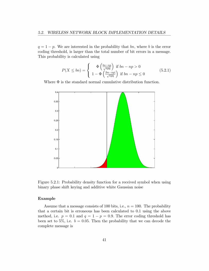
q = 1� p. We are interested in the probability that bn; where b is the errorcoding threshold, is larger than the total number of bit errors in a message.This probability is calculated using
P (X � bn) =
8<: ��bn�nppnpq
�if bn� np > 0
1� ��jbn�npjpnpq
�if bn� np � 0
(5.2.1)
Where � is the standard normal cumulative distribution function.
Figure 5.2.1: Probability density function for a received symbol when usingbinary phase shift keying and additive white Gaussian noise
Example
Assume that a message consists of 100 bits, i.e., n = 100. The probabilitythat a certain bit is erroneous has been calculated to 0.1 using the abovemethod, i.e. p = 0:1 and q = 1 � p = 0:9: The error coding threshold hasbeen set to 5%, i.e. b = 0:05: Then the probability that we can decode thecomplete message is
41
5.2. WIRELESS NETWORK BLOCK IMPLEMENTATION DETAILS
P (X � bn) = 1� ��jbn� npjpnpq
�= 1� �
�5p9
�� 0:0478 (5.2.2)
5.2.4 User-de�ned path-loss function
The default path-loss function (or propagation model) used in the TrueTimewireless simulation is
Preceiver =1
daPsender (5.2.3)
where P is the power, d is the distance in meters, and a is a parameterthat can be chosen to model di¤erent environments. This model is often usedin simulations, but in some case it can be advantageous to use other mod-els. Therefore, the function is written as a Matlab m-�le and can thereforetake advantage of all the built-in functions available in Matlab or Simulink.In particular, this includes the possibility to use persistent variables, i.e.,variables which are retained in memory between calls to the function. Thisfunction can, for example, be used to model a Rayleigh fading or blocking ofradio signals to and from certain points in the environment. Coordinates ofnodes are introduced to model directive e¤ects in the antenna behavior.The Matlab function takes the following arguments
� Transmission power
� Name of the sending node
� x y and z coordinates of the sending node
� Name of the receiving node
� x y and z coordinates of the receiving node
� Current simulation time
and returns the signal power in the receiving node.
42
5.3. TRUETIME COMMANDS DETAILS
5.3 TrueTime commands details
TrueTime furnishes a wide library of commands, written as C++ func-tions , that can be used by users to program initialization scripts, task codefunctions and interrupt handler code functions.Each command has a pre�x tt in its name and by typing help com-
mand, where command is the name of a TrueTime function, in the Matlabcommand window, the syntax of the various TrueTime functions will bedisplayed.
ttInitKernel command
To initialize the kernel block the command ttInitKernel is used. Thisfunction performs necessary initializations and must be called �rst of all inthe initialization script. It takes the following arguments:
nbrInp: Number of input channels, i.e. the size of the A/D port of thekernel block.
nbrOutp: Number of output channels, i.e. the size of the D/A port of thekernel block.
prioFcn: The scheduling policy used by the kernel. There are prede�nedpriority functions called prioFP, prioRM, prioDM, and prioEDF.
prioFcn: The scheduling policy used by the kernel. There are prede�nedpriority functions called prioFP, prioRM, prioDM, and prioEDF.
cs_oh: The overhead time for a full context switch. Unless speci�ed, zerooverhead will be associated with context switches.
ttCreateTask and ttCreatePeriodicTask commands
In the initialization script, user can use the commands ttCreateTaskand ttCreatePeriodicTask to create periodic or aperiodic tasks. Aperi-odic tasks are triggered by the creation of task jobs, using the commandttCreateJob. All pending jobs are inserted in a job queue of the task sortedby release time. For periodic task an internal timer is set up to periodicallycreate jobs for the task.
43
5.3. TRUETIME COMMANDS DETAILS
In particular, the command ttCreateTask, takes the following argu-ments:
name: Name of the task. Must be a unique, non-empty string.
deadline: Relative deadline of the task.
Priority: Priority of the task. This should be a value greater thanzero, where a small number represents a high priority. Only relevantfor �xed-priority scheduling.
codeFcn: The code function of the task, where codeFcn is a string(name of an m-�le) in the Matlab case and a function pointer in theC++ case.
data: An arbitrary data structure representing the local memory ofthe task.
ttCreatePeriodicTask takes the following arguments:
name: Name of the task. Must be a unique, non-empty string.
o¤set: Release time for the �rst job of the periodic task.
period: Period of the task.
priority: Priority of the task. This should be a value greater thanzero, where a small number represents a high priority. Only relevantfor �xed-priority scheduling.
codeFcn: The code function of the task, where codeFcn is a string(name of an m-�le) in the Matlab case and a function pointer in theC++ case.
data: An arbitrary data structure representing the local memory ofthe task.
44
5.3. TRUETIME COMMANDS DETAILS
ttInitNetwork command
It is also necessary to initialize the network block and this is done byusing the ttInitNetwork command. It is used both for wired and wirelessnetworks and must be used before any messages can be sent or received. Thefunction takes the following arguments:
network: The number of the TrueTime network block. The defaultnetwork number is one.
nodenumber: The address of the node in the network. Must be anumber between one and the number of nodes as speci�ed in the dialogof the corresponding TrueTime network block.
handlername: The name of an interrupt handler that should be in-voked when a message arrives over the network.
ttSendMsg and ttGetMsg commands
Each node in the network is able to send or receive messages. It is possibleto use standalone network blocks, named ttSendMsg and ttGetMsg withoutusing kernel blocks, or resort to the utilization of two commands inside thetask code function. They are named, as standalone blocks, ttSendMsg andttGetMsg. ttSendMsg takes the following arguments:
network: The network interface on which the message should be sent. Thedefault network number is 1.
receiver: The number of the receiving node (a number between 1 and thenumber of nodes). It is allowed to send messages to oneself. Specifyreceiver number 0 to broadcast a message to all nodes in the network.
data: An arbitrary data structure representing the contents of the message.
length: The length of the message, in bits. Determines the time it willtake to transmit the message.
priority: The priority of the message (relevant only for CSMA/AMP net-works). If not speci�ed, the priority will be given by the number ofthe sending node, i.e. messages sent from node 1 will have the highestpriority by default.
45
5.3. TRUETIME COMMANDS DETAILS
ttGetMsg takes instead the two parameters:
network: The network interface from which the message should be re-ceived. The default network number is 1.
signalPower: The value of the received signal power corresponding to thismessage. It is only used in the wireless network.
Typically, user has been noti�ed that a message exists in the networkinterface input queue by an interrupt, but it is also possible to poll for newmessages.
46
Chapter 6
TrueTime Extension
6.1 Introduction
This chapter will explain how TrueTime has been modi�ed in orderto emulate the ECMA368 standard. The �exibility of the tool is given bythe possibility of extending or creating C++ functions with correspondingMATLAB MEX-interfaces. Two di¤erent approaches have been followedto model the two medium access methods de�ned by the standard (DRPand PCA). In both cases the new functionalities of the simulator have beenimplemented utilizing the cooperation between C++ functions and speci�cTrueTime tasks (described by m-functions). The main di¤erence is that inthe DRP case each device performs its own MAC protocol, calling a C++function, instead, in the PCA case a centralized function manages the MACprotocol of all nodes. In addition, the graphic interface has been modifed inorder to simplify the setting up of parameters needed for simulations.
6.2 DRP implementation for SMV tra¢ c
SMV tra¢ c is continuous stream of samples (256 bytes every 250�s inour case). Since the UWB channel is shared among all the devices belongingto the network, devices has to aggregate several SMV samples in a MACframe that can be transmitted in its reserved MAS. In order to emulate thisbehaviour, during the simulation, each device executes continuously a speci�cTrueTime task. The following pseudo-code explains its behaviour:
47
6.3. PCA IMPLEMENTATION
function dev_sendcode
1. Call ttECMA368_DRP commandSet the time of next task execution (using ttSetPeriod command)if there are no MAC frames to send
goto 4 (using ttSetNextSegment command)
2. Wait before sending the MAC frame
3. Send one MAC frame (using ttSendMsg command)if there is another MAC frame to send
goto 2 (using ttSetNextSegment command)
4. End
In this code, the commands ttECMA368_DRP, ttSetPeriod, ttSetNextSegmentand ttSendMsg are used. ttECMA368_DRP has been created to implementthe new functionalities described later. Other commands are already imple-mented in TrueTime [21] .The task dev_sendcode is executed at the �rst time like an initialization.
In this case, ttECMA368_DRP and ttSetPeriod are used to allow the deviceto execute again this task at the beginning of its next reserved slot. Inaddition to the functionality above described, ttECMA368_DRP is used in thenext iterations to build the MAC frame aggregating SMV samples, accordingto ECMA368 speci�cs. With values calculated in this way the ttSendMsgperforms the packet transmission.With this solution the wireless network block is only responsible for the
messages propagation over the channel. Since transmissions in a waveguideare free of disturbances and with a very low path loss, the channel has beenassumed ideal.
6.3 PCA implementation
In order to emulate the PCA protocol, a new C++ function is executedonce at the beginning of the simulation. Its main features are:
48
6.3. PCA IMPLEMENTATION
� To generate information about the tra¢ c that will be produced by allthe nodes during the simulation. This information is stored in a datastructure.
� To perform the centralized PCA algorithm on the data structure.
� To build an output data structure containing the actual time of datatransmission for all nodes.
With this approach each node must know the behaviour that the othernodes will adopt until the end of the simulation.
6.3.1 Tra¢ c generation
The function has been implemented so that it is possible to perform acombined transmission of SMV and SCADA data. The function generates avector that contains information about the node producing tra¢ c, the time itwould like to transmit and the message type, SMV or SCADA. SMV samplesare generated every 250�s and they have a length of 256 bytes. It is possibleto choose how many SMV samples that should be bu¤erized and aggregatedin a single frame. The frame length is �xed and depends on the numberof samples per frame. SCADA packets are generated following the typicalcon�guration in which 2 packets of 183 bytes are sent every second on average.In order to emulate the SCADA tra¢ c behaviour, information are randomly-generated. Further, as provided for SCADA applications, an ACK policy atthe application layer has been considered. In this case, application layer ACKpackets are seen as data packets at the MAC layer and they are generatedwith SCADA messages. The transmission has been emulated taking intoaccount the generated time of SCADA packets and adding a random periodcalculated with a normal distribution with a mean of 15ms; as explained inSec. 5.2. In this way the delay with which the station controller acknowledgesSCADA messages has been modeled.It is possible to emulate only SCADA tra¢ c or both SMV and SCADA
tra¢ c, selecting it by the TrueTime graphic interface. If SCADA tra¢ c isselected a con�guration in which SMV data are sent using DRP protocol isassumed and SCADA messages will be sent in slots reserved for PCA.
49
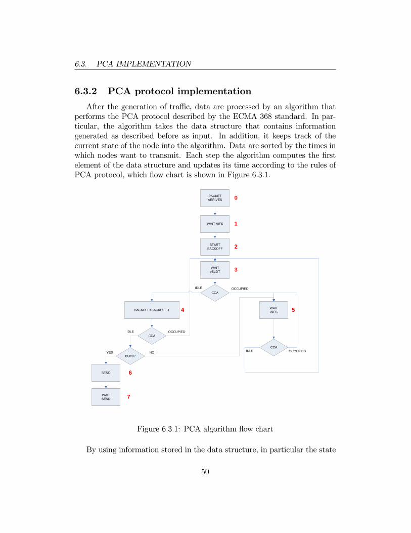
6.3. PCA IMPLEMENTATION
6.3.2 PCA protocol implementation
After the generation of tra¢ c, data are processed by an algorithm thatperforms the PCA protocol described by the ECMA 368 standard. In par-ticular, the algorithm takes the data structure that contains informationgenerated as described before as input. In addition, it keeps track of thecurrent state of the node into the algorithm. Data are sorted by the times inwhich nodes want to transmit. Each step the algorithm computes the �rstelement of the data structure and updates its time according to the rules ofPCA protocol, which �ow chart is shown in Figure 6.3.1.
PACKETARRIVES
CCA
STARTBACKOFF
WAIT AIFS
SEND
WAITpSLOT
WAITAIFSBACKOFF=BACKOFF1
CCA
CCA
BO=0?
WAITSEND
OCCUPIED
OCCUPIED
OCCUPIED
IDLE
IDLE
IDLE
YES NO
0
6
54
3
1
2
7
Figure 6.3.1: PCA algorithm �ow chart
By using information stored in the data structure, in particular the state
50
6.3. PCA IMPLEMENTATION
of the node and the times of the messages, and by re-sorting the data struc-ture when a node changes its state, it is possible to execute the data process-ing in parallel. When all actual times of data transmission are calculated,the algorithm terminates and stores these values in an output data structurethat will be utilized by a speci�c TrueTime task, responsible of sendingmessages over the network.
6.3.3 Messages transmission
When a device wants to transmit data using the PCA protocol, it executesa task that implements the following pseudo-code:
function dev_snd_code
1. Take data from PCA C++ function (using ttECMA_MAC_PCA command)if there are no MAC frames to send
goto 4
2. Wait before sending
3. Send one MAC frame (using ttSendMsg command)if there is another MAC frame to send
goto 2
4. End
Values returned by the Wireless Network function are put in the Mat-lab workspace. This is realized with a new command ,ttECMA368_MAC_PCA,that acts as an interface between the C++ code and Matlab. The nodesends all the packets it has generated using the command ttSendMsg. There-fore, the code is re-executed in a cyclic way with the use of the commandttSetNextSegment.
6.3.4 Proxy implementation
For the simulation, a behaviour of a proxy that communicates with theoutside network has been modeled. It receives data from nodes and sends
51
6.4. WIRELESS NETWORK MASK MODIFICATION
ACK packets in response to them. In particular, the Imm-ACK policy de-scribed by the ECMA 368 has been considered at the MAC layer. Further,for SCADA tra¢ c an ACK policy at the application layer is allowed. Thebehaviour of the task used to send MAC layer ACK packets is explained bythe following pseudo-code:
function proxy_send_code
1. Receive a message from a node
2. Wait a SIFS
3. Send ACK packet (using ttSendMsg command)
4. End
When the proxy receives a packet from a node it sends an ACK with aduration of 15�s; according to the Imm-ACK frame duration described byECMA 368. The packet is sent after a SIFS interval of 10�s:Application layer ACKs have been considered as data packets and so sent
using the task described in sec 7.3.3.
6.4 Wireless network mask modi�cation
The Wireless network mask in TrueTime has been modi�ed. Now itis possible to choose the ECMA368 standard with all parameters neededfor simulations. In particular, modi�cations has been made on the base ofthe extended version of TrueTime, that comprises the WirelessHart option.WirelessHart has been implemented in a recent work, performed at the ABBCorporate Research. The new �elds in the mask are shown in Figure 6.4.1.
52
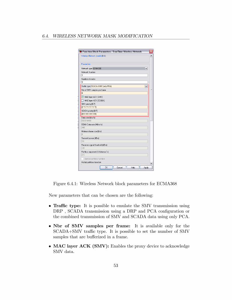
6.4. WIRELESS NETWORK MASK MODIFICATION
Figure 6.4.1: Wireless Network block parameters for ECMA368
New parameters that can be chosen are the following:
� Tra¢ c type: It is possible to emulate the SMV transmission usingDRP , SCADA transmission using a DRP and PCA con�guration orthe combined transmission of SMV and SCADA data using only PCA.
� Nbr of SMV samples per frame: It is available only for theSCADA+SMV tra¢ c type. It is possible to set the number of SMVsamples that are bu¤erized in a frame.
� MAC layer ACK (SMV): Enables the proxy device to acknowledgeSMV data.
53
6.4. WIRELESS NETWORK MASK MODIFICATION
� MAC layer ACK (SCADA): Enables the proxy device to acknowl-edge SCADA data. An acknowledgment policy for this kind of data isalready provided by higher layers.
� SMV priority: The priority for SMV data can be set for each node inthe network. According to PCA, priority can assume a value between0 and 7, but usually for SMV data the highest priority (7) is assumed.
� SCADA priority: The priority for SCADA data can be set for eachnode in the network. According to PCA, priority can assume a valuebetween 0 and 7, but usually for SCADA data the lowest priority (0)is assumed.
Since the maximum data rate of 480 Mbit/s has been considered in thework, the data rate �eld has been �xed to 503316480 bits/s (480 Mbits/s).However, the interface is predisposed to accept the other bit rates speci�edby ECMA 368 that can be implemented in future works. A �eld ECMAData rate has been added, now �xed to the value of 480 Mbit/s. Extendingthe already modi�ed graphic interface, the size of the slot and the size ofthe superframe has been set respectively to 256 �s and 256, according tothe superframe structure of the standard. Since in the work the channel hasbeen assumed ideal, physical parameters used by the other protocols havebeen disabled.
54
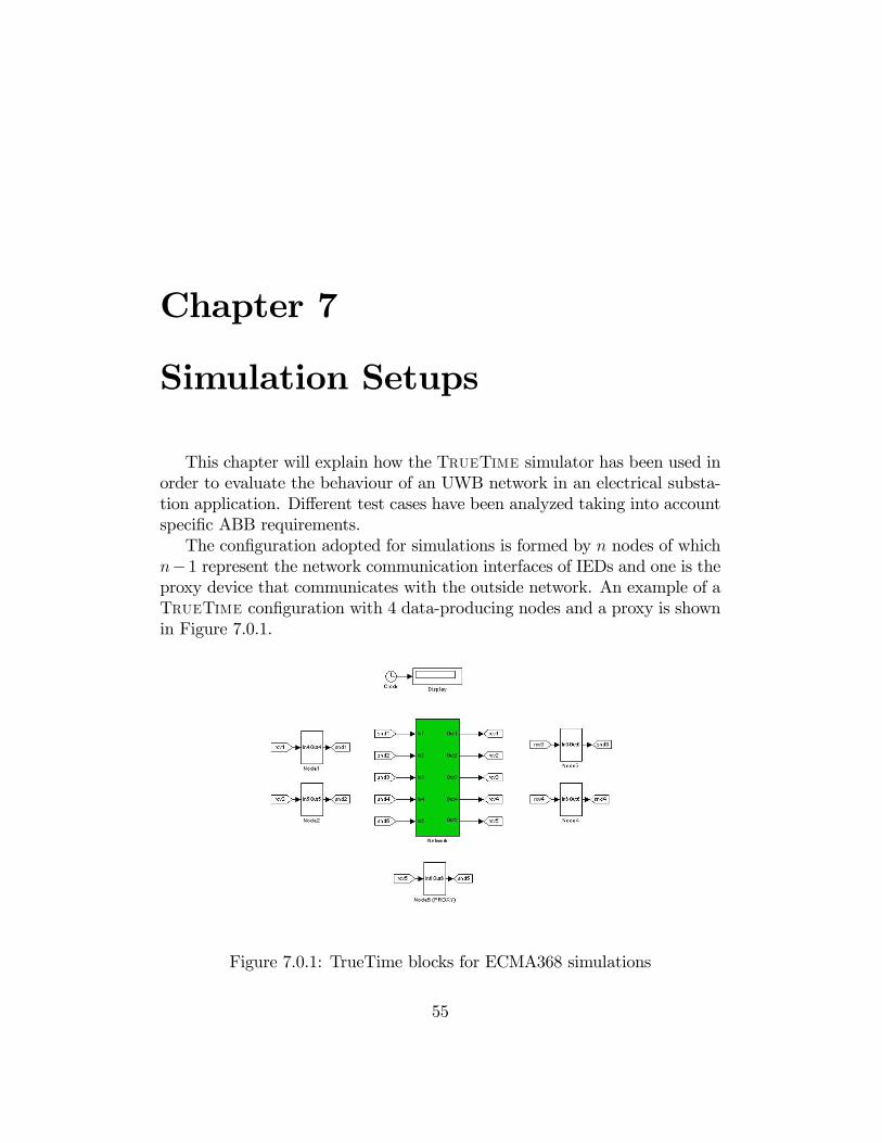
Chapter 7
Simulation Setups
This chapter will explain how the TrueTime simulator has been used inorder to evaluate the behaviour of an UWB network in an electrical substa-tion application. Di¤erent test cases have been analyzed taking into accountspeci�c ABB requirements.The con�guration adopted for simulations is formed by n nodes of which
n�1 represent the network communication interfaces of IEDs and one is theproxy device that communicates with the outside network. An example of aTrueTime con�guration with 4 data-producing nodes and a proxy is shownin Figure 7.0.1.
Figure 7.0.1: TrueTime blocks for ECMA368 simulations
55
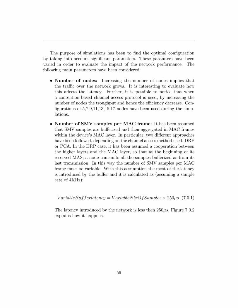
The purpose of simulations has been to �nd the optimal con�gurationby taking into account signi�cant parameters. These paramters have beenvaried in order to evaluate the impact of the network performance. Thefollowing main parameters have been considered:
� Number of nodes: Increasing the number of nodes implies thatthe tra¢ c over the network grows. It is interesting to evaluate howthis a¤ects the latency. Further, it is possible to notice that whena contention-based channel access protocol is used, by increasing thenumber of nodes the troughput and hence the e¢ ciency decrease. Con-�gurations of 5,7,9,11,13,15,17 nodes have been used during the simu-lations.
� Number of SMV samples per MAC frame: It has been assumedthat SMV samples are bu¤erized and then aggregated in MAC frameswithin the device�s MAC layer. In particular, two di¤erent approacheshave been followed, depending on the channel access method used, DRPor PCA. In the DRP case, it has been assumed a cooperation betweenthe higher layers and the MAC layer, so that at the beginning of itsreserved MAS, a node transmits all the samples bu¤erized as from itslast transmission. In this way the number of SMV samples per MACframe must be variable. With this assumption the most of the latencyis introduced by the bu¤er and it is calculated as (assuming a samplerate of 4KHz):
V ariableBufferlatency = V ariableNbrOfSamples� 250�s (7.0.1)
The latency introduced by the network is less then 250�s: Figure 7.0.2explains how it happens.
56
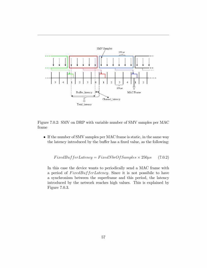
Figure 7.0.2: SMV on DRP with variable number of SMV samples per MACframe
� If the number of SMV samples per MAC frame is static, in the same waythe latency introduced by the bu¤er has a �xed value, as the following:
FixedBufferLatency = FixedNbrOfSamples� 250�s (7.0.2)
In this case the device wants to periodically send a MAC frame witha period of FixedBufferLatency: Since it is not possibile to havea synchronism between the superframe and this period, the latencyintroduced by the network reaches high values. This is explained byFigure 7.0.3.
57
Figure 7.0.3: SMV on DRP with �xed number of SMV samples per MACframe
In the PCA case, the number of SMV samples per MAC frame hasbeen assumed �xed. This parameter has a big impact on the networkperformance because increasing it the throughput grows. On the otherhand, increasing the number of bu¤erized samples, the MAC frameduration becomes longer and it will a¤ect latency.
Figure 7.0.4 [20] shows the relationship between the theoretical maxi-mum throughput and packet size for MBOA MAC with PHY mode of480Mb/s.
58

Figure 7.0.4: TMT of MBOA DRP and PCA
For con�gurations utilized in simulations each IED produces both SMVand SCADA data according to the following parameters:
Size(Byte) Rate(Hertz) Load(Mb/s)SMV 256B 4KHz SMVload � 8Mb=sSCADA 183B 2Hz SCADAload � 3Kb=s
Table 7.0.1: Parameters for SMV and SCADA data
The tra¢ c produced by each IED is:
IEDload = SMVload + SCADAload � 8Mb=s (7.0.3)
59
Thus, the throughput of the network (NT) must ful�l the followingexpression:
NT > Nbr_of_IEDs� IEDload (7.0.4)
The proxy device transmits only ACK messages and its tra¢ c has notbeen taken into account. By resting on these considerations, the choiceof the number of SMV samples per MAC frame sets out a lower bound-ary for the number of nodes. Its impact on the latency will be shownwith simulation results.
� ACK policy: The choice of an ACK policy according to the stan-dard features in�uences in the same way the network performance. Insimulations, a No-ACK policy and a Imm-ACK policy have been con-sidered.
� Priority: In the ECMA 368 standard the PCA protocol allows a prior-ity management. In simulations the highest priority (7) and the lowestpriority (0) have been used for SMV data and for SCADA data respec-tively.
60
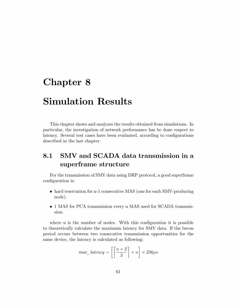
Chapter 8
Simulation Results
This chapter shows and analyzes the results obtained from simulations. Inparticular, the investigation of network performance has be done respect tolatency. Several test cases have been evaluated, according to con�gurationsdescribed in the last chapter.
8.1 SMV and SCADA data transmission in asuperframe structure
For the transmission of SMV data using DRP protocol, a good superframecon�guration is:
� hard reservation for n-1 consecutive MAS (one for each SMV-producingnode).
� 1 MAS for PCA transmission every n MAS used for SCADA transmis-sion.
where n is the number of nodes. With this con�guration it is possibleto theoretically calculate the maximum latency for SMV data. If the beconperiod occurs between two consecutive transmission opportunities for thesame device, the latency is calculated as following:
max_latency =��n+ 2
3
�+ n
�� 256�s
61
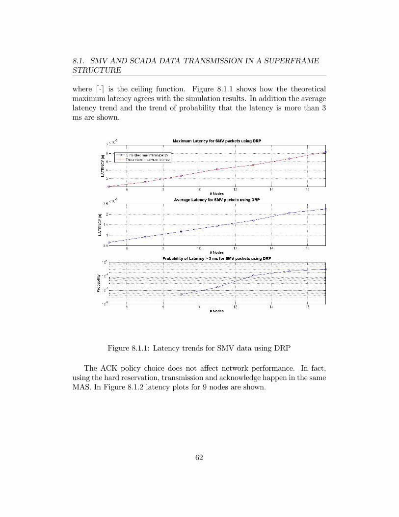
8.1. SMV AND SCADA DATA TRANSMISSION IN A SUPERFRAMESTRUCTURE
where d�e is the ceiling function. Figure 8.1.1 shows how the theoreticalmaximum latency agrees with the simulation results. In addition the averagelatency trend and the trend of probability that the latency is more than 3ms are shown.
Figure 8.1.1: Latency trends for SMV data using DRP
The ACK policy choice does not a¤ect network performance. In fact,using the hard reservation, transmission and acknowledge happen in the sameMAS. In Figure 8.1.2 latency plots for 9 nodes are shown.
62
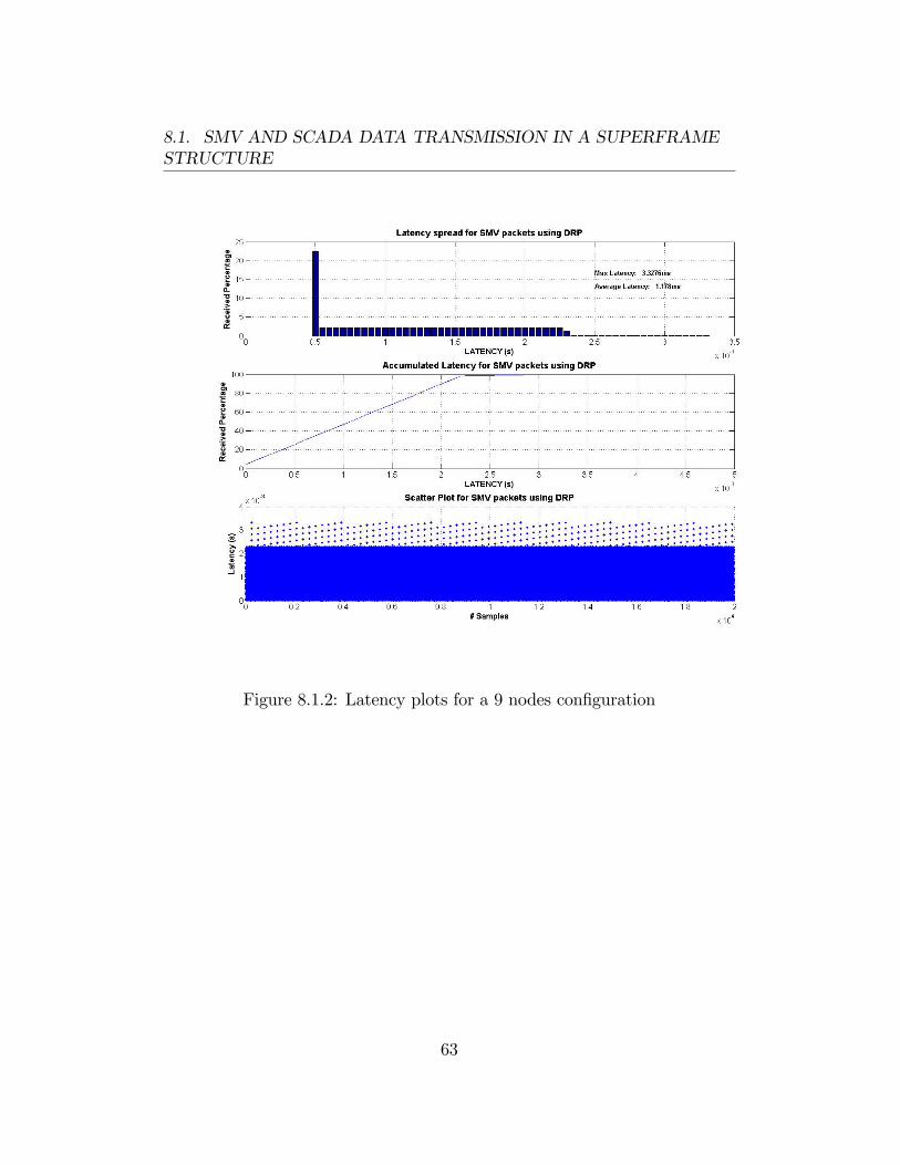
8.1. SMV AND SCADA DATA TRANSMISSION IN A SUPERFRAMESTRUCTURE
Figure 8.1.2: Latency plots for a 9 nodes con�guration
63
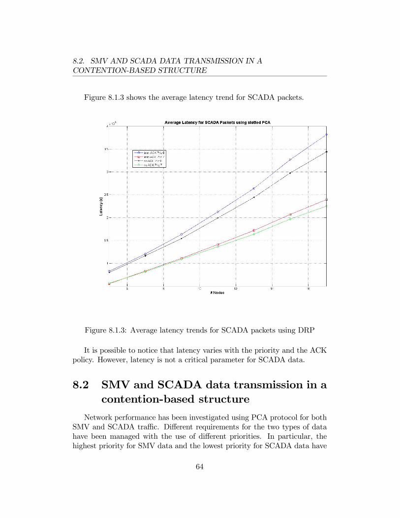
8.2. SMV AND SCADA DATA TRANSMISSION IN ACONTENTION-BASED STRUCTURE
Figure 8.1.3 shows the average latency trend for SCADA packets.
Figure 8.1.3: Average latency trends for SCADA packets using DRP
It is possible to notice that latency varies with the priority and the ACKpolicy. However, latency is not a critical parameter for SCADA data.
8.2 SMV and SCADA data transmission in acontention-based structure
Network performance has been investigated using PCA protocol for bothSMV and SCADA tra¢ c. Di¤erent requirements for the two types of datahave been managed with the use of di¤erent priorities. In particular, thehighest priority for SMV data and the lowest priority for SCADA data have
64
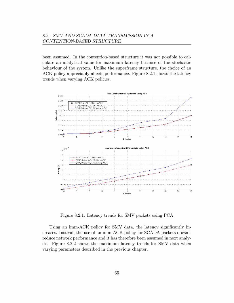
8.2. SMV AND SCADA DATA TRANSMISSION IN ACONTENTION-BASED STRUCTURE
been assumed. In the contention-based structure it was not possible to cal-culate an analytical value for maximum latency because of the stochasticbehaviour of the system. Unlike the superframe structure, the choice of anACK policy appreciably a¤ects performance. Figure 8.2.1 shows the latencytrends when varying ACK policies.
Figure 8.2.1: Latency trends for SMV packets using PCA
Using an imm-ACK policy for SMV data, the latency signi�cantly in-creases. Instead, the use of an imm-ACK policy for SCADA packets doesn�treduce network performance and it has therefore been assumed in next analy-sis. Figure 8.2.2 shows the maximum latency trends for SMV data whenvarying parameters described in the previous chapter.
65
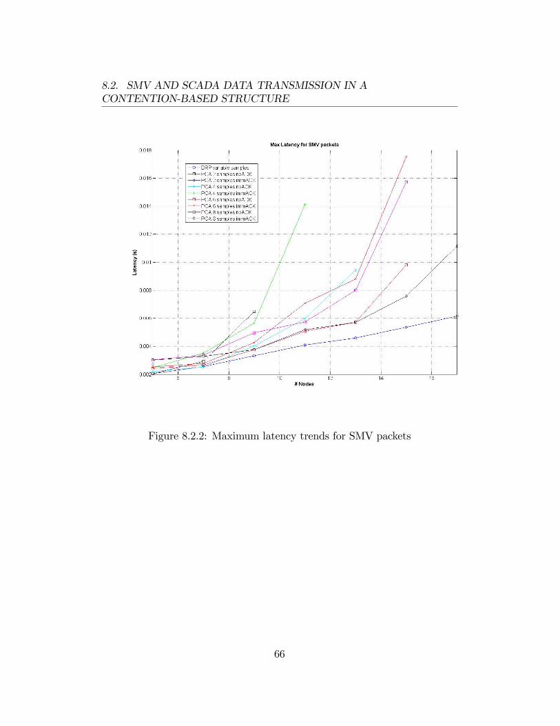
8.2. SMV AND SCADA DATA TRANSMISSION IN ACONTENTION-BASED STRUCTURE
Figure 8.2.2: Maximum latency trends for SMV packets
66
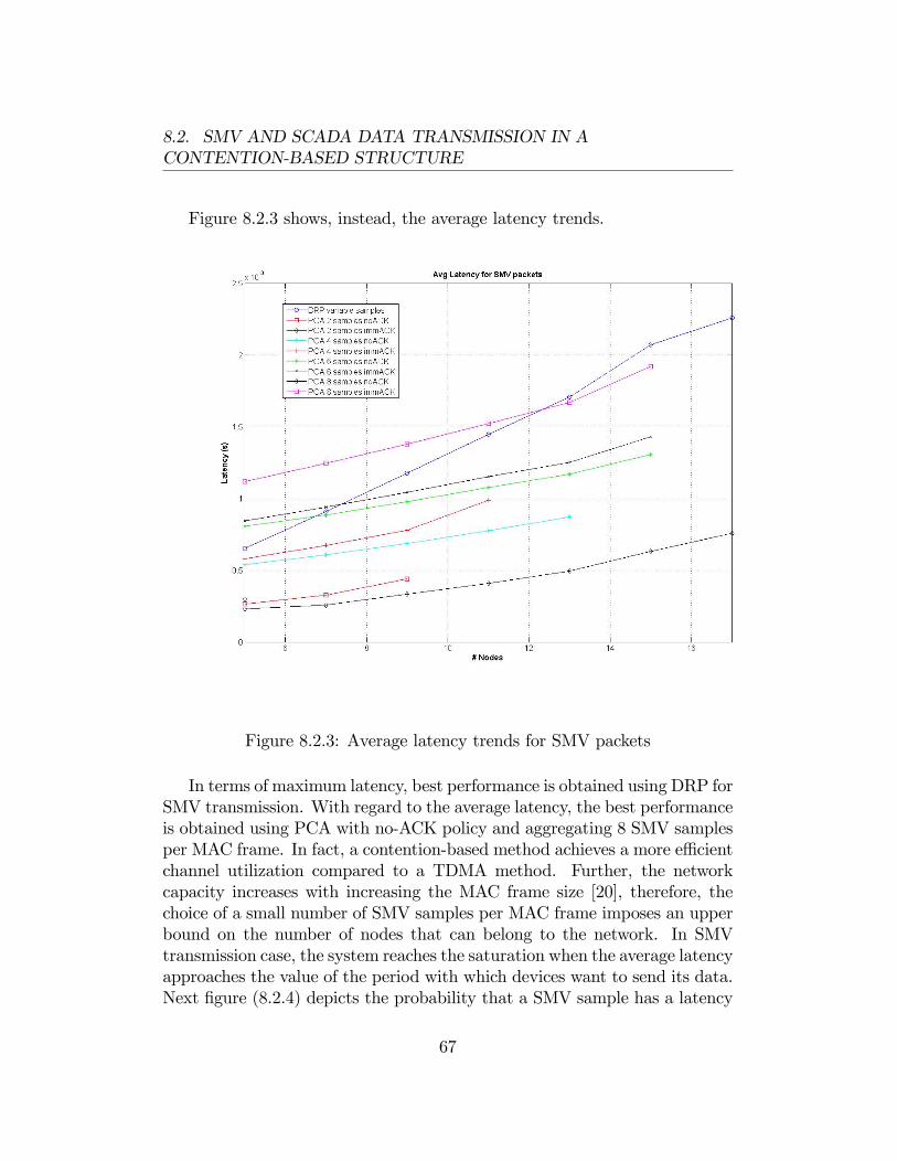
8.2. SMV AND SCADA DATA TRANSMISSION IN ACONTENTION-BASED STRUCTURE
Figure 8.2.3 shows, instead, the average latency trends.
Figure 8.2.3: Average latency trends for SMV packets
In terms of maximum latency, best performance is obtained using DRP forSMV transmission. With regard to the average latency, the best performanceis obtained using PCA with no-ACK policy and aggregating 8 SMV samplesper MAC frame. In fact, a contention-based method achieves a more e¢ cientchannel utilization compared to a TDMA method. Further, the networkcapacity increases with increasing the MAC frame size [20], therefore, thechoice of a small number of SMV samples per MAC frame imposes an upperbound on the number of nodes that can belong to the network. In SMVtransmission case, the system reaches the saturation when the average latencyapproaches the value of the period with which devices want to send its data.Next �gure (8.2.4) depicts the probability that a SMV sample has a latency
67
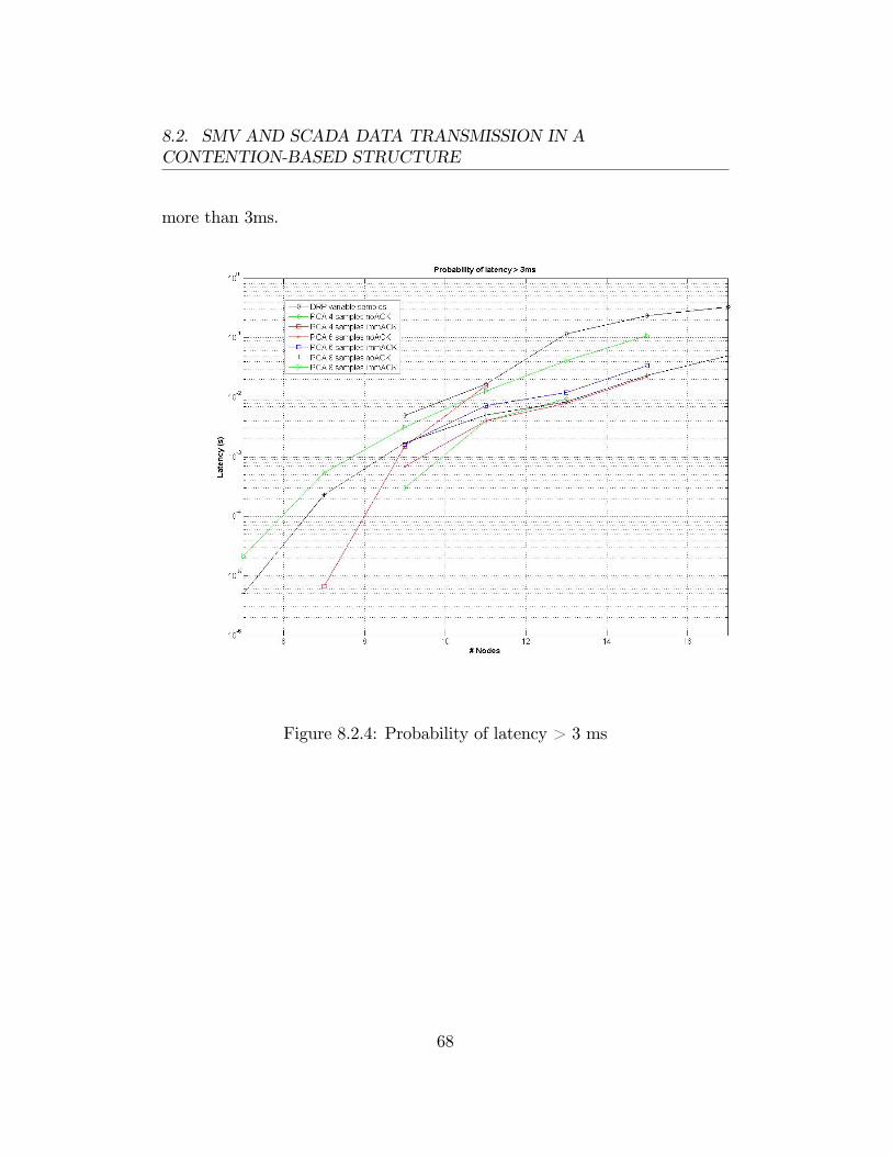
8.2. SMV AND SCADA DATA TRANSMISSION IN ACONTENTION-BASED STRUCTURE
more than 3ms.
Figure 8.2.4: Probability of latency > 3 ms
68
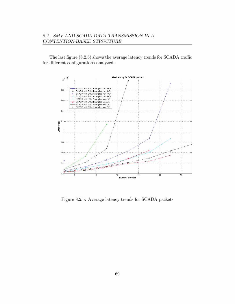
8.2. SMV AND SCADA DATA TRANSMISSION IN ACONTENTION-BASED STRUCTURE
The last �gure (8.2.5) shows the average latency trends for SCADA tra¢ cfor di¤erent con�gurations analyzed.
Figure 8.2.5: Average latency trends for SCADA packets
69
Chapter 9
Conclusions
The main aim of this work has been to evaluate performance of a net-work consisting of several UWB nodes communicating data according to aspeci�c scheme (de�ned by an ABB switchgear application), in a simula-tion software environment. TrueTime, a Matlab/Simulink-based simulatorhas been extended to comply with the ECMA368 standard. The latter hasbeen adopted by WiMedia Alliance for the development of Wireless USBtechnology and seems to be able to satisfy the IEC61850 requirements. Inparticular, the simulator has been conceived to emulate transmission of SMV(hard real-time) and SCADA (best-e¤ort) data over the network utilizing thetwo channel access methods described by ECMA368, DRP and PCA. Twodi¤erent approaches have been followed in order to implement the protocols.For DRP, a C++ function that perform the MAC protocol for each nodehas been implemented, instead, for PCA, a centralized function performs theprotocol for all nodes. Speci�c TrueTime tasks have been used in coopera-tion with these functions to emulate transmission of SMV and SCADA datain the same link. In this way, it has been possible to analyze the latencyintroduced by the transmission and compare it with ABB requirements. Alltransmissions have been assumed in an ideal channel and using a data rateof 480Mb/s, allowed by ECMA368. Furthermore, we have assumed that theUWB communication is realized using 3 sub-bands (1.5GHz total bandwidth)according to the standard. Analyzing results obtained from simulations ithas been noticed that best performance in terms of maximum latency areguaranteed using DRP for SMV tra¢ c and leaving periodically a slot forSCADA transmission performed with PCA protocol. The utilization of PCAfor both SMV and SCADA data, assuming the highest priority for the �rst
70

and the lowest priority for the second, gives the best performance in termsof average latency. This is more evident when the number of SMV samplesaggregated in a MAC frame is increased. In fact, for contention-based meth-ods, the network throughput increases when increasing the MAC frame size.Utilizing PCA for SMV transmission a performance degradation has beennoticed when a imm-ACK policy is used.On the basis of these considerations, we think that UWB is a technology
suitable for applications in electrical substations. In fact, it complies theABB requirements if number of IEDs belonging to the network is less than10. For applications in bigger substations (with an high number of devices),we think that it could be possible to satisfy the same requirements utilizingmore waveguide segments. In this way, each segment could use a distinctsub-network which could communicate with the other sub-networks throughproxy devices.Future work of this project might be the utilization of the simulator for
evaluating performance of the whole network when more sub-networks areused. Further, the development of a channel model studying the propagationof UWB signals inside a waveguide could be useful. The ECMA368 simulatorcan be extended taking into account this channel model. Further, it could beinteresting to investigate network performance varying bit rates as allowedby ECMA368 standard.
71
Appendix A
Simulation Results Plots
In this section the simulation results plots of all the evaluated test caseswill be shown. In particular each �gure depicts the latency spread or theaccumulated latency for each con�guration which has been simulated.
72
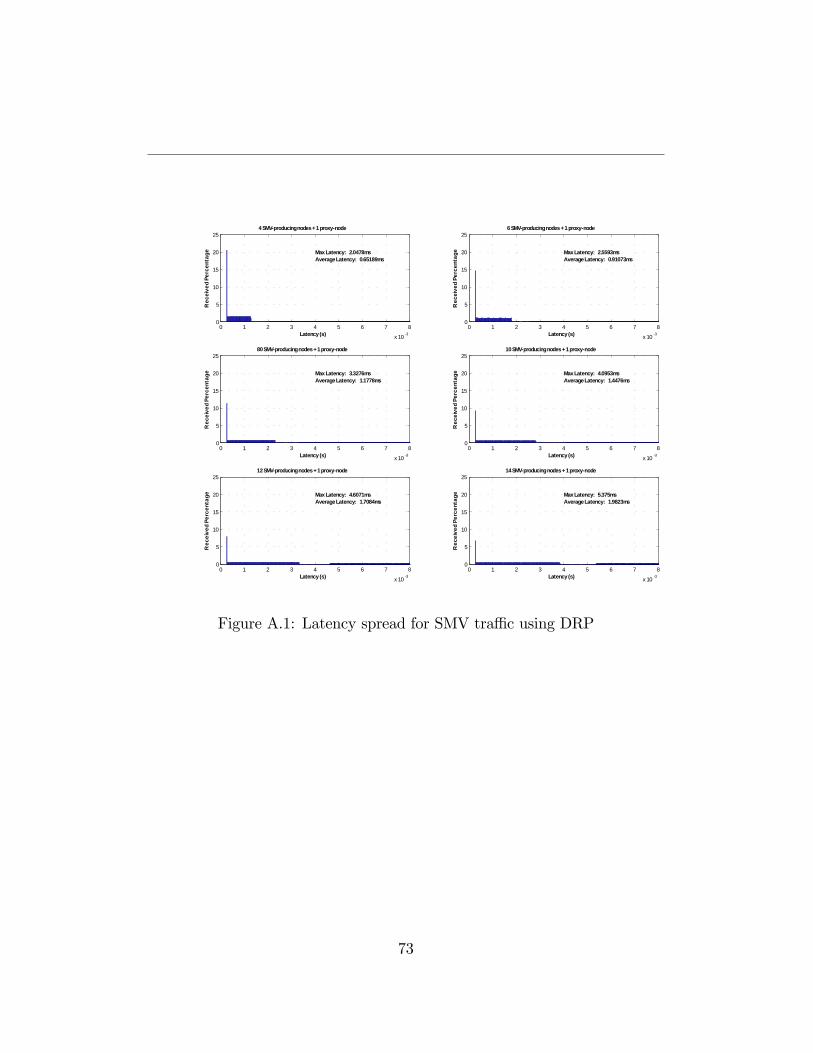
0 1 2 3 4 5 6 7 8
x 10 3
0
5
10
15
20
25
Latency (s)
Rec
eive
d Pe
rcen
tage
4 SMVproducing nodes + 1 proxynode
Max Latency: 2.0478msAverage Latency: 0.65189ms
0 1 2 3 4 5 6 7 8
x 10 3
0
5
10
15
20
256 SMVproducing nodes + 1 proxynode
Max Latency: 2.5593msAverage Latency: 0.91073ms
Latency (s)
Rec
eive
d Pe
rcen
tage
0 1 2 3 4 5 6 7 8
x 10 3
0
5
10
15
20
2580 SMVproducing nodes + 1 proxynode
Max Latency: 3.3276msAverage Latency: 1.1778ms
Latency (s)
Rec
eive
d Pe
rcen
tage
0 1 2 3 4 5 6 7 8
x 10 3
0
5
10
15
20
2510 SMVproducing nodes + 1 proxynode
Max Latency: 4.0953msAverage Latency: 1.4476ms
Latency (s)R
ecei
ved
Perc
enta
ge
0 1 2 3 4 5 6 7 8
x 10 3
0
5
10
15
20
2512 SMVproducing nodes + 1 proxynode
Max Latency: 4.6071msAverage Latency: 1.7084ms
Latency (s)
Rec
eive
d Pe
rcen
tage
0 1 2 3 4 5 6 7 8
x 10 3
0
5
10
15
20
2514 SMVproducing nodes + 1 proxynode
Max Latency: 5.375msAverage Latency: 1.9823ms
Latency (s)
Rec
eive
d Pe
rcen
tage
Figure A.1: Latency spread for SMV tra¢ c using DRP
73
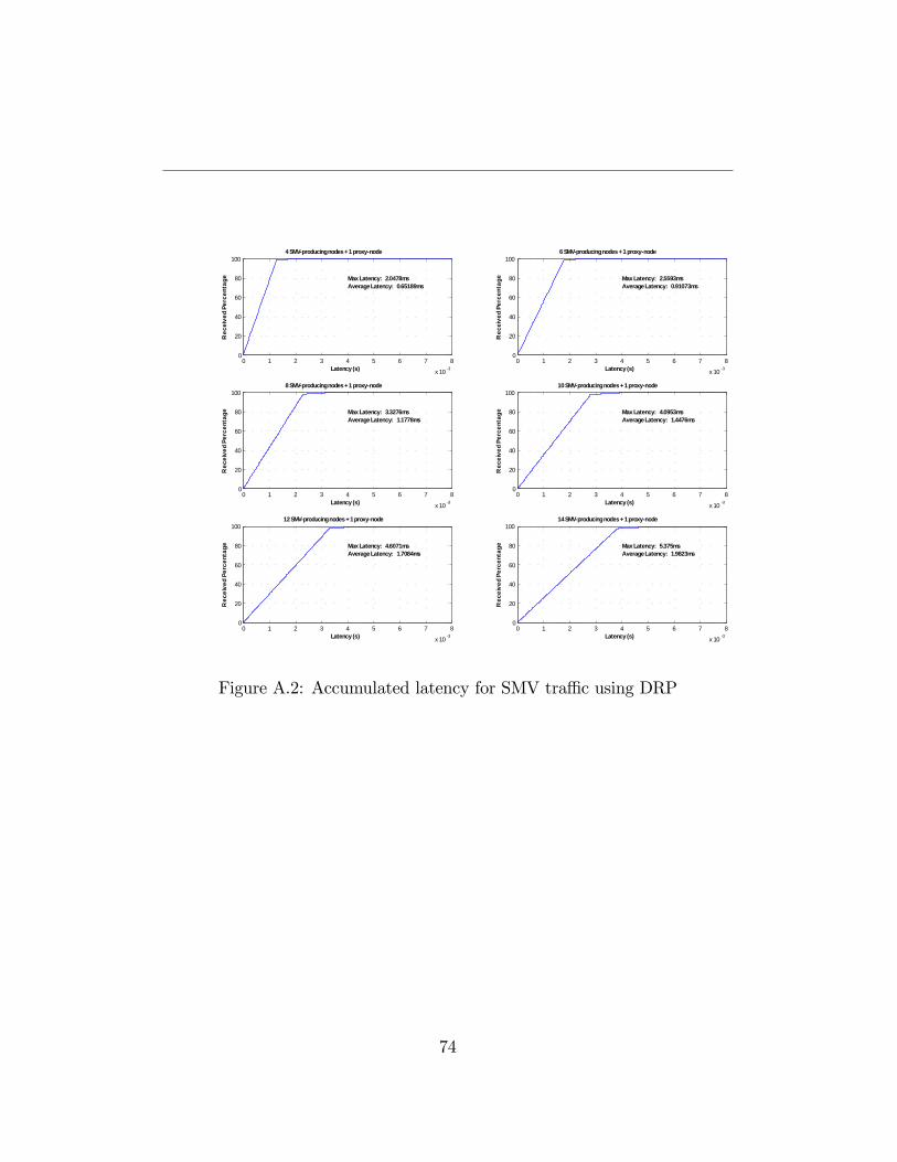
0 1 2 3 4 5 6 7 8
x 10 3
0
20
40
60
80
100
Max Latency: 2.0478msAverage Latency: 0.65189ms
4 SMVproducing nodes + 1 proxynode
Latency (s)
Rec
eive
d Pe
rcen
tage
0 1 2 3 4 5 6 7 8
x 10 3
0
20
40
60
80
100
Max Latency: 2.5593msAverage Latency: 0.91073ms
6 SMVproducing nodes + 1 proxynode
Latency (s)
Rec
eive
d Pe
rcen
tage
0 1 2 3 4 5 6 7 8
x 10 3
0
20
40
60
80
100
Max Latency: 3.3276msAverage Latency: 1.1778ms
8 SMVproducing nodes + 1 proxynode
Latency (s)
Rec
eive
d Pe
rcen
tage
0 1 2 3 4 5 6 7 8
x 10 3
0
20
40
60
80
100
Max Latency: 4.0953msAverage Latency: 1.4476ms
10 SMVproducing nodes + 1 proxynode
Latency (s)R
ecei
ved
Perc
enta
ge
0 1 2 3 4 5 6 7 8
x 10 3
0
20
40
60
80
100
Max Latency: 4.6071msAverage Latency: 1.7084ms
12 SMVproducing nodes + 1 proxynode
Latency (s)
Rec
eive
d Pe
rcen
tage
0 1 2 3 4 5 6 7 8
x 10 3
0
20
40
60
80
100
Max Latency: 5.375msAverage Latency: 1.9823ms
14 SMVproducing nodes + 1 proxynode
Latency (s)
Rec
eive
d Pe
rcen
tage
Figure A.2: Accumulated latency for SMV tra¢ c using DRP
74
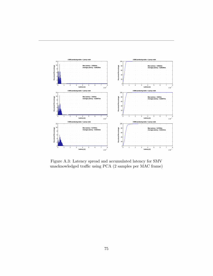
0 1 2 3 4 5 6 7 8
x 10 3
0
2
4
6
8
10
124 SMVproducing nodes + 1 proxynode
Latency (s)
Rec
eive
d Pe
rcen
tage Max Latency: 2.0564ms
Average Latency: 0.26529ms
0 1 2 3 4 5 6 7 8
x 10 3
0
2
4
6
8
10
12
Max Latency: 2.924msAverage Latency: 0.32607ms
6 SMVproducing nodes + 1 proxynode
Latency (s)
Rec
eive
d Pe
rcen
tage
0 1 2 3 4 5 6 7 8
x 10 3
0
2
4
6
8
10
12
Max Latency: 6.4729msAverage Latency: 0.44101ms
8 SMVproducing nodes + 1 proxynode
Latency (s)
Rec
eive
d Pe
rcen
tage
0 1 2 3 4 5 6 7 8
x 10 3
0
20
40
60
80
100
Max Latency: 2.0564msAverage Latency: 0.26529ms
4 SMVproducing nodes + 1 proxynode
Latency (s)
Rec
eive
d Pe
rcen
tage
0 1 2 3 4 5 6 7 8
x 10 3
0
20
40
60
80
100
Max Latency: 2.924msAverage Latency: 0.32607ms
6 SMVproducing nodes + 1 proxynode
Latency (s)R
ecei
ved
Perc
enta
ge
0 1 2 3 4 5 6 7 8
x 10 3
0
20
40
60
80
100
Max Latency: 6.4729msAverage Latency: 0.44101ms
8 SMVproducing nodes + 1 proxynode
Latency (s)
Rec
eive
d Pe
rcen
tage
Figure A.3: Latency spread and accumulated latency for SMVunacknowledged tra¢ c using PCA (2 samples per MAC frame)
75
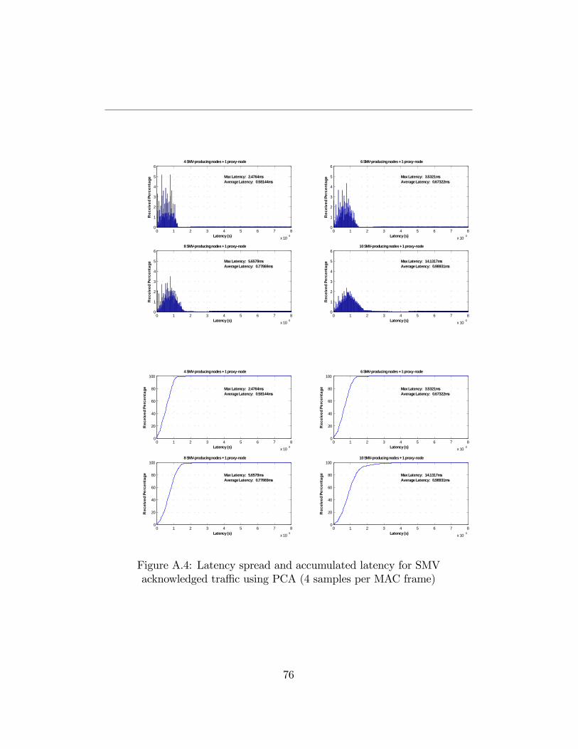
0 1 2 3 4 5 6 7 8
x 10 3
0
1
2
3
4
5
64 SMVproducing nodes + 1 proxynode
Latency (s)
Rec
eive
d Pe
rcen
tage
Max Latency: 2.4764msAverage Latency: 0.58144ms
0 1 2 3 4 5 6 7 8
x 10 3
0
1
2
3
4
5
66 SMVproducing nodes + 1 proxynode
Max Latency: 3.5321msAverage Latency: 0.67322ms
Latency (s)
Rec
eive
d Pe
rcen
tage
0 1 2 3 4 5 6 7 8
x 10 3
0
1
2
3
4
5
68 SMVproducing nodes + 1 proxynode
Max Latency: 5.6579msAverage Latency: 0.77869ms
Latency (s)
Rec
eive
d Pe
rcen
tage
0 1 2 3 4 5 6 7 8
x 10 3
0
1
2
3
4
5
610 SMVproducing nodes + 1 proxynode
Max Latency: 14.1317msAverage Latency: 0.98931ms
Latency (s)R
ecei
ved
Perc
enta
ge
0 1 2 3 4 5 6 7 8
x 10 3
0
20
40
60
80
100
Max Latency: 2.4764msAverage Latency: 0.58144ms
4 SMVproducing nodes + 1 proxynode
Latency (s)
Rec
eive
d Pe
rcen
tage
0 1 2 3 4 5 6 7 8
x 10 3
0
20
40
60
80
100
Max Latency: 3.5321msAverage Latency: 0.67322ms
6 SMVproducing nodes + 1 proxynode
Latency (s)
Rec
eive
d Pe
rcen
tage
0 1 2 3 4 5 6 7 8
x 10 3
0
20
40
60
80
100
Max Latency: 5.6579msAverage Latency: 0.77869ms
8 SMVproducing nodes + 1 proxynode
Latency (s)
Rec
eive
d Pe
rcen
tage
0 1 2 3 4 5 6 7 8
x 10 3
0
20
40
60
80
100
Max Latency: 14.1317msAverage Latency: 0.98931ms
10 SMVproducing nodes + 1 proxynode
Latency (s)
Rec
eive
d Pe
rcen
tage
Figure A.4: Latency spread and accumulated latency for SMVacknowledged tra¢ c using PCA (4 samples per MAC frame)
76
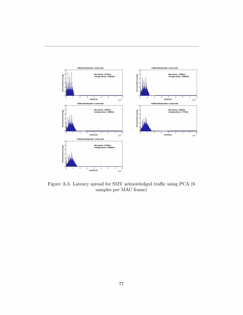
0 1 2 3 4 5 6 7 8
x 10 3
0
1
2
3
4
5
64 SMVproducing nodes + 1 proxynode
Latency (s)
Rec
eive
d Pe
rcen
tage
Max Latency: 2.2133msAverage Latency: 0.54041ms
0 1 2 3 4 5 6 7 8
x 10 3
0
1
2
3
4
5
66 SMVproducing nodes + 1 proxynode
Max Latency: 2.5399msAverage Latency: 0.60883ms
Latency (s)
Rec
eive
d Pe
rcen
tage
0 1 2 3 4 5 6 7 8
x 10 3
0
1
2
3
4
5
68 SMVproducing nodes + 1 proxynode
Max Latency: 4.0265msAverage Latency: 0.6856ms
Latency (s)
Rec
eive
d Pe
rcen
tage
0 1 2 3 4 5 6 7 8
x 10 3
0
1
2
3
4
5
610 SMVproducing nodes + 1 proxynode
Max Latency: 5.9816msAverage Latency: 0.7745ms
Latency (s)R
ecei
ved
Perc
enta
ge
0 1 2 3 4 5 6 7 8
x 10 3
0
1
2
3
4
5
610 SMVproducing nodes + 1 proxynode
Max Latency: 9.4429msAverage Latency: 0.86996ms
Latency (s)
Rec
eive
d Pe
rcen
tage
Figure A.5: Latency spread for SMV acknowledged tra¢ c using PCA (6samples per MAC frame)
77
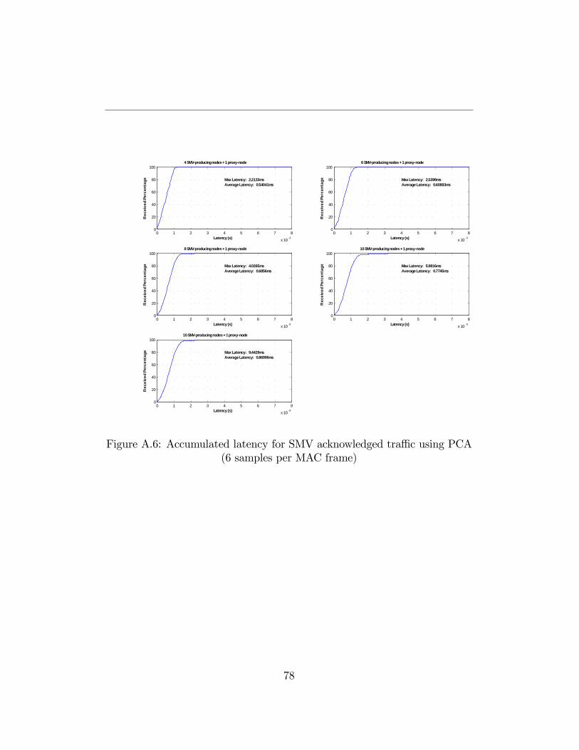
0 1 2 3 4 5 6 7 8
x 10 3
0
20
40
60
80
100
Max Latency: 2.2133msAverage Latency: 0.54041ms
4 SMVproducing nodes + 1 proxynode
Latency (s)
Rec
eive
d Pe
rcen
tage
0 1 2 3 4 5 6 7 8
x 10 3
0
20
40
60
80
100
Max Latency: 2.5399msAverage Latency: 0.60883ms
6 SMVproducing nodes + 1 proxynode
Latency (s)
Rec
eive
d Pe
rcen
tage
0 1 2 3 4 5 6 7 8
x 10 3
0
20
40
60
80
100
Max Latency: 4.0265msAverage Latency: 0.6856ms
8 SMVproducing nodes + 1 proxynode
Latency (s)
Rec
eive
d Pe
rcen
tage
0 1 2 3 4 5 6 7 8
x 10 3
0
20
40
60
80
100
Max Latency: 5.9816msAverage Latency: 0.7745ms
10 SMVproducing nodes + 1 proxynode
Latency (s)R
ecei
ved
Perc
enta
ge
0 1 2 3 4 5 6 7 8
x 10 3
0
20
40
60
80
100
Max Latency: 9.4429msAverage Latency: 0.86996ms
10 SMVproducing nodes + 1 proxynode
Latency (s)
Rec
eive
d Pe
rcen
tage
Figure A.6: Accumulated latency for SMV acknowledged tra¢ c using PCA(6 samples per MAC frame)
78
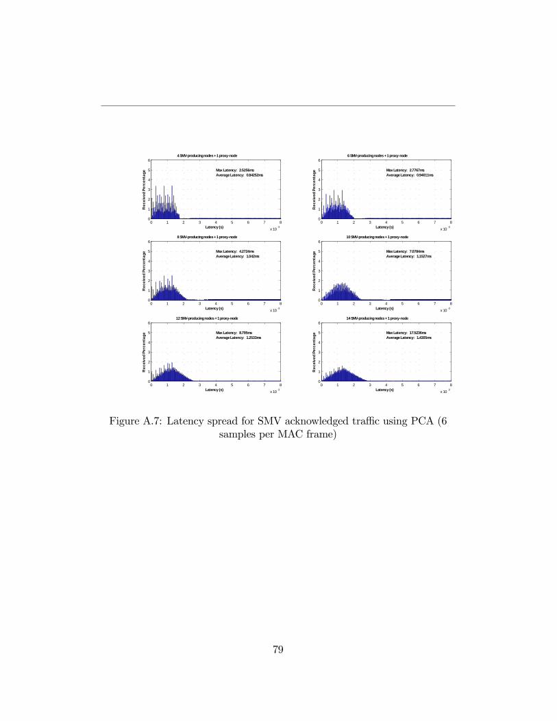
0 1 2 3 4 5 6 7 8
x 10 3
0
1
2
3
4
5
6
Latency (s)
Rec
eive
d Pe
rcen
tage
4 SMVproducing nodes + 1 proxynode
Max Latency: 2.5256msAverage Latency: 0.84252ms
0 1 2 3 4 5 6 7 8
x 10 3
0
1
2
3
4
5
66 SMVproducing nodes + 1 proxynode
Max Latency: 2.7767msAverage Latency: 0.94011ms
Latency (s)
Rec
eive
d Pe
rcen
tage
0 1 2 3 4 5 6 7 8
x 10 3
0
1
2
3
4
5
68 SMVproducing nodes + 1 proxynode
Max Latency: 4.2724msAverage Latency: 1.042ms
Latency (s)
Rec
eive
d Pe
rcen
tage
0 1 2 3 4 5 6 7 8
x 10 3
0
1
2
3
4
5
610 SMVproducing nodes + 1 proxynode
Max Latency: 7.0784msAverage Latency: 1.1527ms
Latency (s)R
ecei
ved
Perc
enta
ge
0 1 2 3 4 5 6 7 8
x 10 3
0
1
2
3
4
5
612 SMVproducing nodes + 1 proxynode
Max Latency: 8.795msAverage Latency: 1.2533ms
Latency (s)
Rec
eive
d Pe
rcen
tage
0 1 2 3 4 5 6 7 8
x 10 3
0
1
2
3
4
5
6
Max Latency: 17.5236msAverage Latency: 1.4305ms
14 SMVproducing nodes + 1 proxynode
Latency (s)
Rec
eive
d Pe
rcen
tage
Figure A.7: Latency spread for SMV acknowledged tra¢ c using PCA (6samples per MAC frame)
79
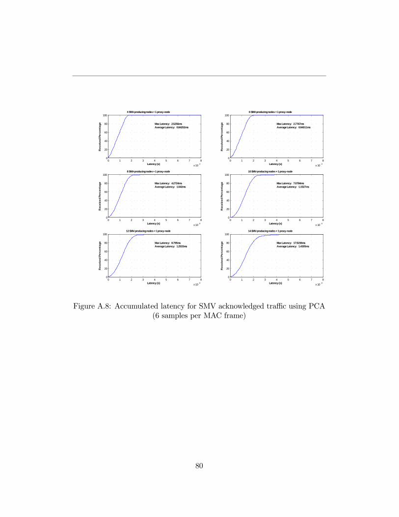
0 1 2 3 4 5 6 7 8
x 10 3
0
20
40
60
80
100
Max Latency: 2.5256msAverage Latency: 0.84252ms
4 SMVproducing nodes + 1 proxynode
Latency (s)
Rec
eive
d Pe
rcen
tage
0 1 2 3 4 5 6 7 8
x 10 3
0
20
40
60
80
100
Max Latency: 2.7767msAverage Latency: 0.94011ms
6 SMVproducing nodes + 1 proxynode
Latency (s)
Rec
eive
d Pe
rcen
tage
0 1 2 3 4 5 6 7 8
x 10 3
0
20
40
60
80
100
Max Latency: 4.2724msAverage Latency: 1.042ms
8 SMVproducing nodes + 1 proxynode
Latency (s)
Rec
eive
d Pe
rcen
tage
0 1 2 3 4 5 6 7 8
x 10 3
0
20
40
60
80
100
Max Latency: 7.0784msAverage Latency: 1.1527ms
10 SMVproducing nodes + 1 proxynode
Latency (s)R
ecei
ved
Perc
enta
ge
0 1 2 3 4 5 6 7 8
x 10 3
0
20
40
60
80
100
Max Latency: 8.795msAverage Latency: 1.2533ms
12 SMVproducing nodes + 1 proxynode
Latency (s)
Rec
eive
d Pe
rcen
tage
0 1 2 3 4 5 6 7 8
x 10 3
0
20
40
60
80
100
Max Latency: 17.5236msAverage Latency: 1.4305ms
14 SMVproducing nodes + 1 proxynode
Latency (s)
Rec
eive
d Pe
rcen
tage
Figure A.8: Accumulated latency for SMV acknowledged tra¢ c using PCA(6 samples per MAC frame)
80
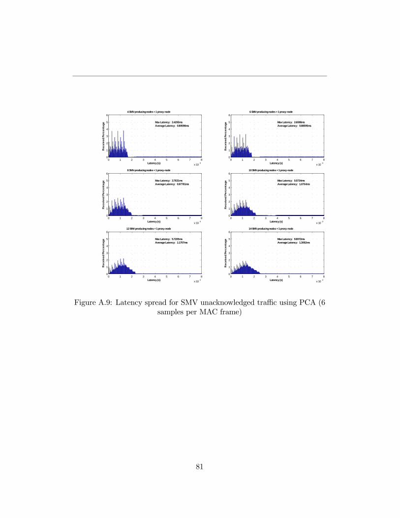
0 1 2 3 4 5 6 7 8
x 10 3
0
1
2
3
4
5
6
Latency (s)
Rec
eive
d Pe
rcen
tage
4 SMVproducing nodes + 1 proxynode
Max Latency: 2.4293msAverage Latency: 0.80598ms
0 1 2 3 4 5 6 7 8
x 10 3
0
1
2
3
4
5
66 SMVproducing nodes + 1 proxynode
Max Latency: 2.6598msAverage Latency: 0.88595ms
Latency (s)
Rec
eive
d Pe
rcen
tage
0 1 2 3 4 5 6 7 8
x 10 3
0
1
2
3
4
5
68 SMVproducing nodes + 1 proxynode
Max Latency: 3.7631msAverage Latency: 0.97781ms
Latency (s)
Rec
eive
d Pe
rcen
tage
0 1 2 3 4 5 6 7 8
x 10 3
0
1
2
3
4
5
610 SMVproducing nodes + 1 proxynode
Max Latency: 5.0734msAverage Latency: 1.0754ms
Latency (s)R
ecei
ved
Perc
enta
ge
0 1 2 3 4 5 6 7 8
x 10 3
0
1
2
3
4
5
612 SMVproducing nodes + 1 proxynode
Max Latency: 5.7205msAverage Latency: 1.1707ms
Latency (s)
Rec
eive
d Pe
rcen
tage
0 1 2 3 4 5 6 7 8
x 10 3
0
1
2
3
4
5
6
Max Latency: 9.8072msAverage Latency: 1.3062ms
14 SMVproducing nodes + 1 proxynode
Latency (s)
Rec
eive
d Pe
rcen
tage
Figure A.9: Latency spread for SMV unacknowledged tra¢ c using PCA (6samples per MAC frame)
81
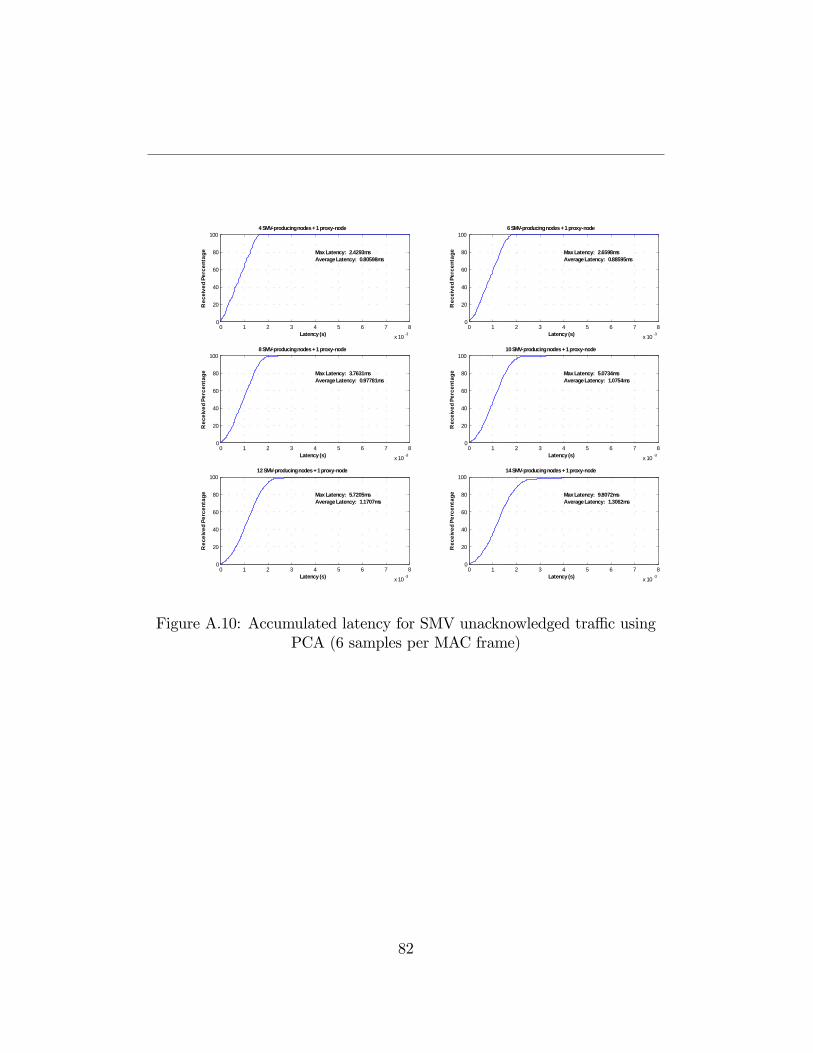
0 1 2 3 4 5 6 7 8
x 10 3
0
20
40
60
80
100
Max Latency: 2.4293msAverage Latency: 0.80598ms
4 SMVproducing nodes + 1 proxynode
Latency (s)
Rec
eive
d Pe
rcen
tage
0 1 2 3 4 5 6 7 8
x 10 3
0
20
40
60
80
100
Max Latency: 2.6598msAverage Latency: 0.88595ms
6 SMVproducing nodes + 1 proxynode
Latency (s)
Rec
eive
d Pe
rcen
tage
0 1 2 3 4 5 6 7 8
x 10 3
0
20
40
60
80
100
Max Latency: 3.7631msAverage Latency: 0.97781ms
8 SMVproducing nodes + 1 proxynode
Latency (s)
Rec
eive
d Pe
rcen
tage
0 1 2 3 4 5 6 7 8
x 10 3
0
20
40
60
80
100
Max Latency: 5.0734msAverage Latency: 1.0754ms
10 SMVproducing nodes + 1 proxynode
Latency (s)R
ecei
ved
Perc
enta
ge
0 1 2 3 4 5 6 7 8
x 10 3
0
20
40
60
80
100
Max Latency: 5.7205msAverage Latency: 1.1707ms
12 SMVproducing nodes + 1 proxynode
Latency (s)
Rec
eive
d Pe
rcen
tage
0 1 2 3 4 5 6 7 8
x 10 3
0
20
40
60
80
100
Max Latency: 9.8072msAverage Latency: 1.3062ms
14 SMVproducing nodes + 1 proxynode
Latency (s)
Rec
eive
d Pe
rcen
tage
Figure A.10: Accumulated latency for SMV unacknowledged tra¢ c usingPCA (6 samples per MAC frame)
82
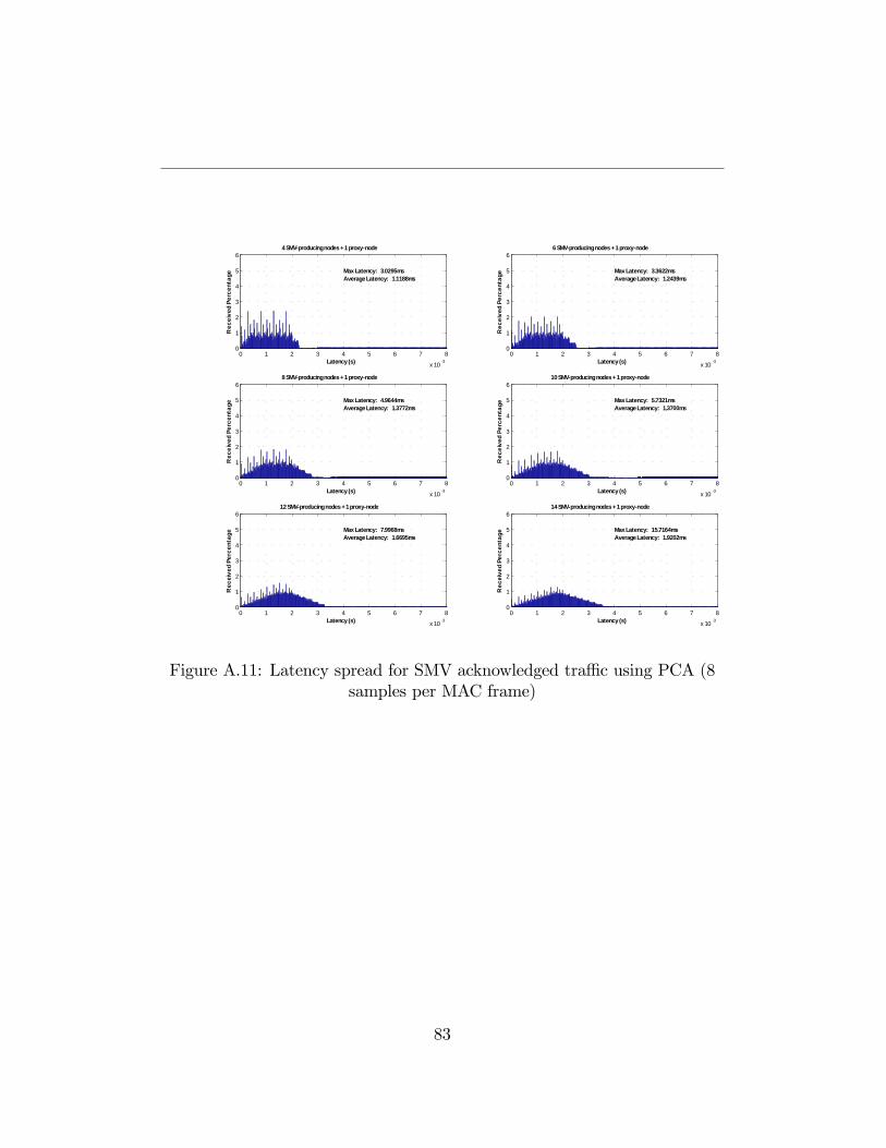
0 1 2 3 4 5 6 7 8
x 10 3
0
1
2
3
4
5
6
Latency (s)
Rec
eive
d Pe
rcen
tage
4 SMVproducing nodes + 1 proxynode
Max Latency: 3.0295msAverage Latency: 1.1188ms
0 1 2 3 4 5 6 7 8
x 10 3
0
1
2
3
4
5
66 SMVproducing nodes + 1 proxynode
Max Latency: 3.3622msAverage Latency: 1.2439ms
Latency (s)
Rec
eive
d Pe
rcen
tage
0 1 2 3 4 5 6 7 8
x 10 3
0
1
2
3
4
5
68 SMVproducing nodes + 1 proxynode
Max Latency: 4.9644msAverage Latency: 1.3772ms
Latency (s)
Rec
eive
d Pe
rcen
tage
0 1 2 3 4 5 6 7 8
x 10 3
0
1
2
3
4
5
610 SMVproducing nodes + 1 proxynode
Max Latency: 5.7321msAverage Latency: 1.3700ms
Latency (s)R
ecei
ved
Perc
enta
ge
0 1 2 3 4 5 6 7 8
x 10 3
0
1
2
3
4
5
612 SMVproducing nodes + 1 proxynode
Max Latency: 7.9968msAverage Latency: 1.6695ms
Latency (s)
Rec
eive
d Pe
rcen
tage
0 1 2 3 4 5 6 7 8
x 10 3
0
1
2
3
4
5
6
Max Latency: 15.7164msAverage Latency: 1.9202ms
14 SMVproducing nodes + 1 proxynode
Latency (s)
Rec
eive
d Pe
rcen
tage
Figure A.11: Latency spread for SMV acknowledged tra¢ c using PCA (8samples per MAC frame)
83
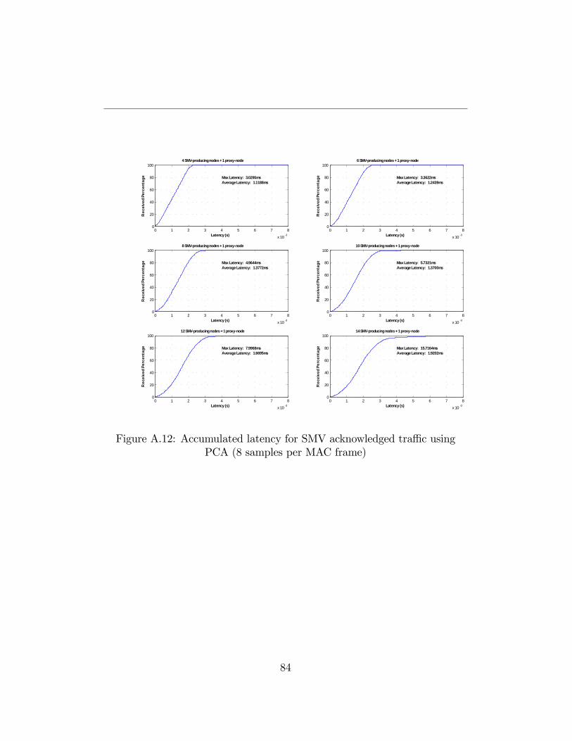
0 1 2 3 4 5 6 7 8
x 10 3
0
20
40
60
80
100
Max Latency: 3.0295msAverage Latency: 1.1188ms
4 SMVproducing nodes + 1 proxynode
Latency (s)
Rec
eive
d Pe
rcen
tage
0 1 2 3 4 5 6 7 8
x 10 3
0
20
40
60
80
100
Max Latency: 3.3622msAverage Latency: 1.2439ms
6 SMVproducing nodes + 1 proxynode
Latency (s)
Rec
eive
d Pe
rcen
tage
0 1 2 3 4 5 6 7 8
x 10 3
0
20
40
60
80
100
Max Latency: 4.9644msAverage Latency: 1.3772ms
8 SMVproducing nodes + 1 proxynode
Latency (s)
Rec
eive
d Pe
rcen
tage
0 1 2 3 4 5 6 7 8
x 10 3
0
20
40
60
80
100
Max Latency: 5.7321msAverage Latency: 1.3700ms
10 SMVproducing nodes + 1 proxynode
Latency (s)R
ecei
ved
Perc
enta
ge
0 1 2 3 4 5 6 7 8
x 10 3
0
20
40
60
80
100
Max Latency: 7.9968msAverage Latency: 1.6695ms
12 SMVproducing nodes + 1 proxynode
Latency (s)
Rec
eive
d Pe
rcen
tage
0 1 2 3 4 5 6 7 8
x 10 3
0
20
40
60
80
100
Max Latency: 15.7164msAverage Latency: 1.9202ms
14 SMVproducing nodes + 1 proxynode
Latency (s)
Rec
eive
d Pe
rcen
tage
Figure A.12: Accumulated latency for SMV acknowledged tra¢ c usingPCA (8 samples per MAC frame)
84
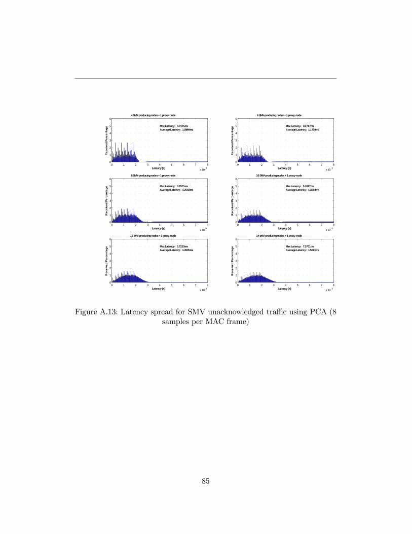
0 1 2 3 4 5 6 7 8
x 10 3
0
1
2
3
4
5
6
Latency (s)
Rec
eive
d Pe
rcen
tage
4 SMVproducing nodes + 1 proxynode
Max Latency: 3.0125msAverage Latency: 1.0869ms
0 1 2 3 4 5 6 7 8
x 10 3
0
1
2
3
4
5
66 SMVproducing nodes + 1 proxynode
Max Latency: 3.2747msAverage Latency: 1.1739ms
Latency (s)
Rec
eive
d Pe
rcen
tage
0 1 2 3 4 5 6 7 8
x 10 3
0
1
2
3
4
5
68 SMVproducing nodes + 1 proxynode
Max Latency: 3.7571msAverage Latency: 1.2643ms
Latency (s)
Rec
eive
d Pe
rcen
tage
0 1 2 3 4 5 6 7 8
x 10 3
0
1
2
3
4
5
610 SMVproducing nodes + 1 proxynode
Max Latency: 5.1827msAverage Latency: 1.3594ms
Latency (s)R
ecei
ved
Perc
enta
ge
0 1 2 3 4 5 6 7 8
x 10 3
0
1
2
3
4
5
612 SMVproducing nodes + 1 proxynode
Max Latency: 5.7253msAverage Latency: 1.4505ms
Latency (s)
Rec
eive
d Pe
rcen
tage
0 1 2 3 4 5 6 7 8
x 10 3
0
1
2
3
4
5
6
Max Latency: 7.5701msAverage Latency: 1.5591ms
14 SMVproducing nodes + 1 proxynode
Latency (s)
Rec
eive
d Pe
rcen
tage
Figure A.13: Latency spread for SMV unacknowledged tra¢ c using PCA (8samples per MAC frame)
85
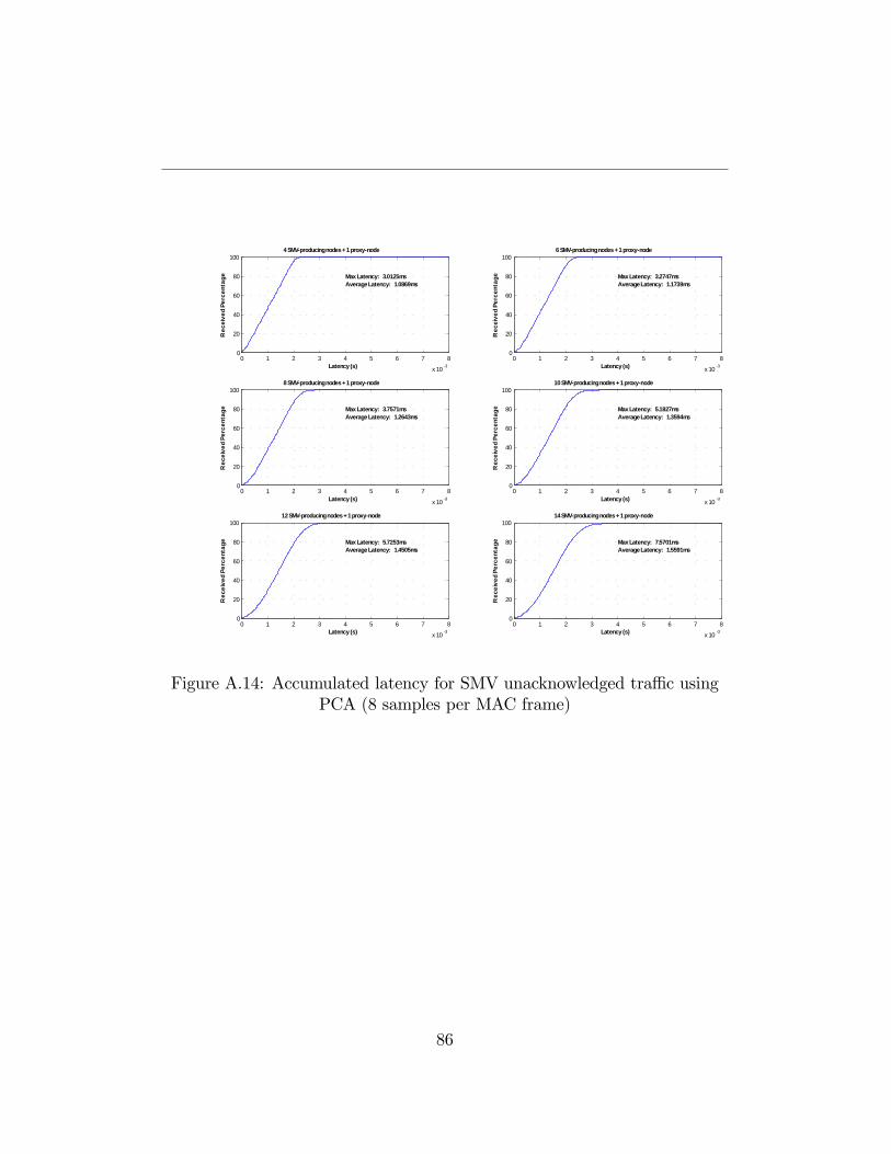
0 1 2 3 4 5 6 7 8
x 10 3
0
20
40
60
80
100
Max Latency: 3.0125msAverage Latency: 1.0869ms
4 SMVproducing nodes + 1 proxynode
Latency (s)
Rec
eive
d Pe
rcen
tage
0 1 2 3 4 5 6 7 8
x 10 3
0
20
40
60
80
100
Max Latency: 3.2747msAverage Latency: 1.1739ms
6 SMVproducing nodes + 1 proxynode
Latency (s)
Rec
eive
d Pe
rcen
tage
0 1 2 3 4 5 6 7 8
x 10 3
0
20
40
60
80
100
Max Latency: 3.7571msAverage Latency: 1.2643ms
8 SMVproducing nodes + 1 proxynode
Latency (s)
Rec
eive
d Pe
rcen
tage
0 1 2 3 4 5 6 7 8
x 10 3
0
20
40
60
80
100
Max Latency: 5.1827msAverage Latency: 1.3594ms
10 SMVproducing nodes + 1 proxynode
Latency (s)R
ecei
ved
Perc
enta
ge
0 1 2 3 4 5 6 7 8
x 10 3
0
20
40
60
80
100
Max Latency: 5.7253msAverage Latency: 1.4505ms
12 SMVproducing nodes + 1 proxynode
Latency (s)
Rec
eive
d Pe
rcen
tage
0 1 2 3 4 5 6 7 8
x 10 3
0
20
40
60
80
100
Max Latency: 7.5701msAverage Latency: 1.5591ms
14 SMVproducing nodes + 1 proxynode
Latency (s)
Rec
eive
d Pe
rcen
tage
Figure A.14: Accumulated latency for SMV unacknowledged tra¢ c usingPCA (8 samples per MAC frame)
86
Bibliography
[1] Overview of substation design and layout [Online] Available:http://www.eng.uwi.tt/depts/elec/sta¤/alvin/ee35t/notes/Substation-Design.html
[2] Klaus-Peter Brand, ABB Switzerland Ltd, Baden, Switzerland MarcoJanssen, AMEC SPIE Special Services, Breda, The Netherlands Thespeci�cation of IEC 61850 based substation automation system
[3] Ivan De Mesmaeker, Peter Rietmann, Klaus-Peter Brand, Petra Rein-hardt Substation Automation based on IEC 61850 Cigré SC B5 6thRegional CIGRÉ conference in Cairo, November 21 �23, 2005
[4] Communication networks and systems in substations - Part 1: Intro-duction and overview, IEC/TR 61850-1:2003(E)
[5] Mario P. Pozzuoli Ethernet in Substation Automation Applications �Is-sues and Requirements RuggedCom Inc. �Industrial Strength NetworksWoodbridge, Ontario, Canada
[6] Communication networks and systems in substations - Part 7-1: Basiccommunication structure for substation and feeder equipment - Princi-ples and models, IEC 61850-7-1:2003(E)
[7] Communication networks and systems in substations - Part 7-2: Basiccommunication structure for substation and feeder equipment - Abstractcommunication service interface (ACSI), IEC 61850-7-2:2003(E)
[8] Communication networks and systems in substations - Part 8-2: Speci�cCommunication Service Mapping (SCSM) - Mappings to MMS (ISO9506-1 and ISO 9506-2) and to ISO/IEC 8802-3, IEC 61850-8-1:2004(E)
87
BIBLIOGRAPHY
[9] Communication networks and systems in substations - Part 9-1: Speci�cCommunication Service Mapping (SCSM) - Sampled values over serialunidirectional multidrop point to point link, IEC 61850-9-1:2003(E)
[10] Klaus-Peter Brand, Christoph Bruinner, Ivan de Mesmaeker "How touse IEC 61850 in protection and automation" No. 222 - October 2005ELECTRA
[11] Athanasopoulos, A.; Topalis, E.; Antonopoulos, C.; Koubias, S, �Evalu-ation Analysis of the Performance of IEEE 802.11b and IEEE 802.11gStandards�Networking, International Conference on Systems and Inter-national Conference on Mobile Communications and Learning Technolo-gies, 2006. ICN/ICONS/MCL 2006. International Conference on Date:23-29 April 2006, Pages: 141 �141
[12] �IEEE 802.15.4 MAC standard� [Online] Available athttp://www.ieee.org/.
[13] First Report and Order in the Matter of Revision of Part 15 of theCommission�s Rules Regarding Ultra-Wideband Transmission Systems.ET Docket 98�153, Federal Communications Commission, FCC 02�48,April 22, 2002.
[14] An Engineering Discussion Paper on Spectrum Allocations forUltra Wide Band Devices (April 2005) [ Online] Available:http://www.rsm.govt.nz/cms
[15] Ultra Wideband Technology - Obstacles and Opportunitites. PlenaryTalk, European Microwave Conference, 8 October 2007, Munich, Ger-many [Online] Available: http://www.multispectral.com/
[16] MultiBand OFDM Alliance. [Online]. Available:http://www.multibandofdm.org/
[17] Standard ECMA-368 High Rate Ultra Wideband PHY andMAC Standard. 2nd edition (December 2007) [ Online] Available:http://www.ecma-international.org
[18] The Wireless USB Promoter Group. [Online]. Available:http://www.usb.org/wusb
88
BIBLIOGRAPHY
[19] IEEE Standard for Information technology �Telecommunication and in-formation exchange between systems �Local and metropolitan area net-works �Speci�c requirements, Part 11: Wireless Medium Access Con-trol (MAC) and Physical Layer (PHY) speci�cations: Amendment 7:Medium Access Control (MAC) Quality of Service (QoS) Enhancements,IEEE Draft Amendment P802.11e/D11.0, Oct. 2004
[20] Zang, Yunpeng and Hiertz, Guido R. and Habetha, Jörg and Otal, Be-gonya and Sirin, Hamza and Reumerman, Hans-Juergen Towards HighSpeed Wireless Personal Area Network - E¢ ciency Analysis of MBOAMAC In Proceedings of International Workshop on Wireless Ad-HocNetworks 2005 (IWWAN 2005), p. 10, London, UK, 2005.
[21] M. Ohlin, D. Henriksson, A. Cervin - TrueTime 1.5-Reference Manual- Department of Automatic Control Lund University, 2007.
[22] A. Fiorenza Perfomance evaluation of an ECMA368 network in an elec-trical substation application based on IEC61850 Master Thesis Work,ABB Corporate Research
89