Embed Size (px)
Citation preview
AD-A284 361
ARMY RESEARCH LABORATORY i*
Design of Advanced Steels forArmor Applications
Gregory B. Olson and Timothy A. Stephenson
ARL-CR- 1 75 August 1994
Prepared byNorthwestern University
Evanston, IL
under contractDAAL04-91 -C-0073
•\-q(•94--298!l
Approved for public release; distribution unlimited.
94, .7
-.- <~~. 77- ~*:
The findings in this report are not to be construed as an official Departmentof the Army position unless so designated by other authorized documents.
Citation of manufacturer's or trade names does not constitute an officialendorsement or approval of the use thereof.
Destroy this report when it is no longer needed. Do not return it to theoriginator.

REPORT DOCUMENTATION PAGE FomApoeI 0MB No. 0704-0 188
Puclic reporting burden for tnIv cotfection of iniorinaton is esbItimatd to aweragi 1 hiour Per reePorne. incuding the uin. for reviewing instruChiore. ssmircrng existing data sokinces.gathering and Maintlaining the data needed. and cdntrfeftig end renipwing the confectioni of intormasm.f Send contients regdtng fts biirden estmlate or ayoiirt dPec Mod f t"S'01=ectonf Morrecn oud" suggeeborih for reducng tOn burden, to Weehnington IHesduarters Sonnets. kofbrecon for Infornmaton Opereltone and Reports. 1215 Jefferson0a. -4ghwav=.St 24. Aib N30 .VA 22202-4302. aird to Ow~ Oftfic of Mansiaierett end Budget. PW~tOt fedumcoon Prqome(0704-0166).Weehmgtn. DC 20503
1. AGENCY USE ONLY (Leowe DW*) 2. REPORT DATE 3.REPORT TYPE AND DATES COVERED
I August 1994 Final Report 8/30191-7/30/934. TITLE AND SUBTITLE .FU1NDING NUMBERS
Design of Advanced Steels for Armor Applications Contract No.DAAL04-9 l-C-0073
6. AUTHOR(S)
Gregory B. Olson and Timothy A. Stephenson
7. PERFORMING ORGANIZATION NAME(S) AND ADORESS(ES) 8 EFRIGOGNZTO
Northwestern University REPORT NUMBER
Evanston, IL
9. SPONSORtNG/MONITORING AGENCY NAME(S) AND AOORESSqES) III. SPONSORINGIMONITORING
U.S. Army Research Laboratory AEC EOTNME
Watertown, MA 02172-0001ATTN: AMSRL-OP-PR-WT ARL-CR-l175
11. SUPPLEMENTARY NOTES
Morris Azrin COR
128. OISTRIBUTtON/AVAILABIUITY STATEMENT 12b. DISTRIBUIJTON CODE
Approved for public release; distribution unlimited.
13. ABSTRACT (Afeomain200 words)
(See reverse, page ii.)
14. SUBJECT TERMS 15. NUMBER OF PAGES
Armor steels. Secondary hardening steels, Fracture 47PRC CD
toughness 1.PIECD
I?. SECURITY CLASSIFICATION 18. SECURITY CLASSIFICATION 19. SECURITY CLASSIFICATION 20. LIMITATION OF ABSTRACTOF REPORT OF THIS PAGE OF ABSTRACT
Unclassified Unclassified Unclassified ULl
NSN 7540J)01280 5500 Stanciard Fofm .91`'qp Z 'i)l
9- D0 hASI2 IA 1
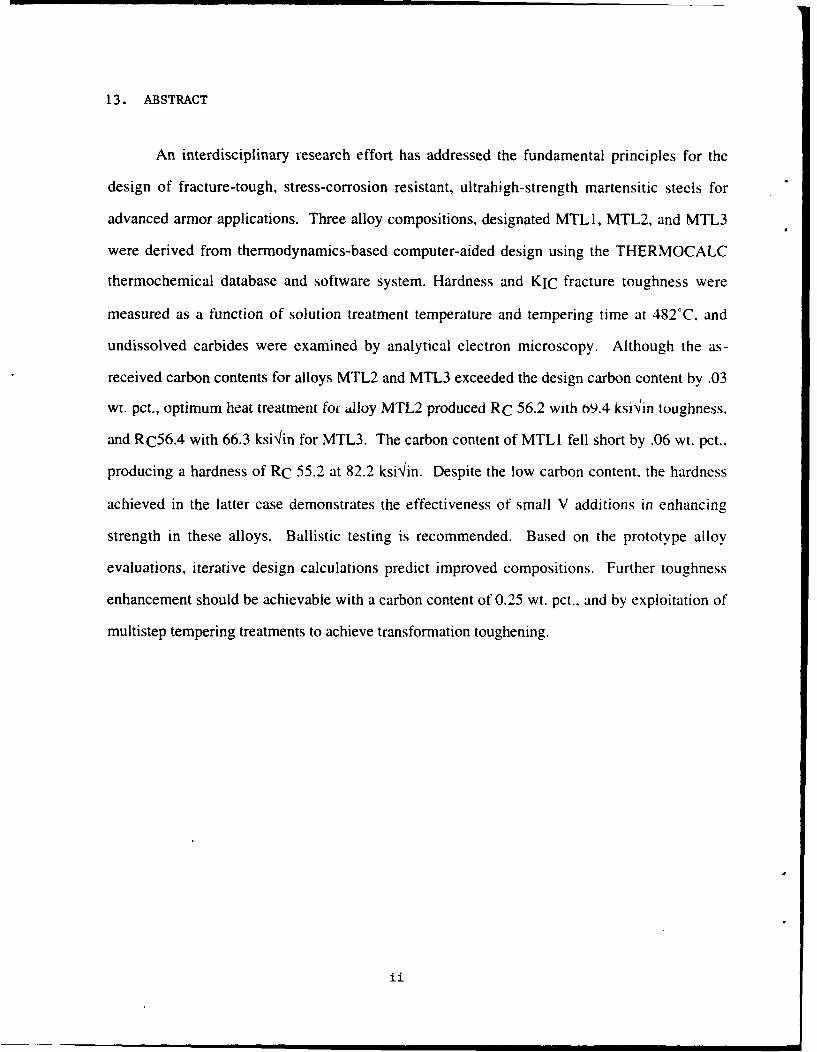
13. ABSTRACT
An interdisciplinary research effort has addressed the fundamental principles for the
design of fracture-tough, stress-corrosion resistant, ultrahigh-strength martensitic steels for
advanced armor applications. Three alloy compositions, designated MTL 1, MTL2, and MTL3
were derived from thermodynamics-based computer-aided design using the THERMOCALC
thermochemical database and software system. Hardness and KIC fracture toughness were
measured as a function of solution treatment temperature and tempering time at 482'C, and
undissolved carbides were examined by analytical electron microscopy. Although the as-
received carbon contents for alloys MTL2 and MTL3 exceeded the design carbon content by .03
wt. pct., optimum heat treatment fo- alloy MTL2 produced RC 56.2 with b9.4 ksiVin toughness,
and RC56.4 with 66.3 ksi'lin for MTL3. The carbon content of MTLI fell short by .06 wt. pct..
producing a hardness of RC 55.2 at 82.2 ksixin. Despite the low carbon content, the hardness
achieved in the latter case demonstrates the effectiveness of small V additions in enhancing
strength in these alloys. Ballistic testing is recommended. Based on the prototype alloy
evaluations, iterative design calculations predict improved compositions. Further toughness
enhancement should be achievable with a carbon content of 0.25 wt. pct., and by exploitation of
multistep tempering treatments to achieve transformation toughening.
1ii
TABLE OF CONTENTS
Introduction .................................................................................................................................... I
Alloy Design .......................................................... 1
T esting and A nalysis .................................................................................................................... 16
Further D esign C alculations ...................................................................................................... 31
Conclusions and Recommendations ......................................................................................... 34
R eferences .................................................................................................................................... 36
Appendix: Processing of Prototype Armor Steels (3 pages)
Ao0oeglon ForITS GRA&I •
DTIC TAB 0Unannounced [
lrst tficlotio
Distribu•t•L.L ,
labvailM Oo
Itat Speoial
Mi

INTRODUCTION
A one-year research effort has applied principles from interdisciplinary
fundamental research under the multi-institutional Steel Research Group (SRG) program
toward the conceptual design of advanced armor steels. Evaluation of three initial
prototype alloys has tested model predictions. Heat treatment optimization of the
prototypes has demonstrated properties worthy of ballistic testing, and provided input for
a second series of design calculations for improved compositions.
ALLOY DESIGN
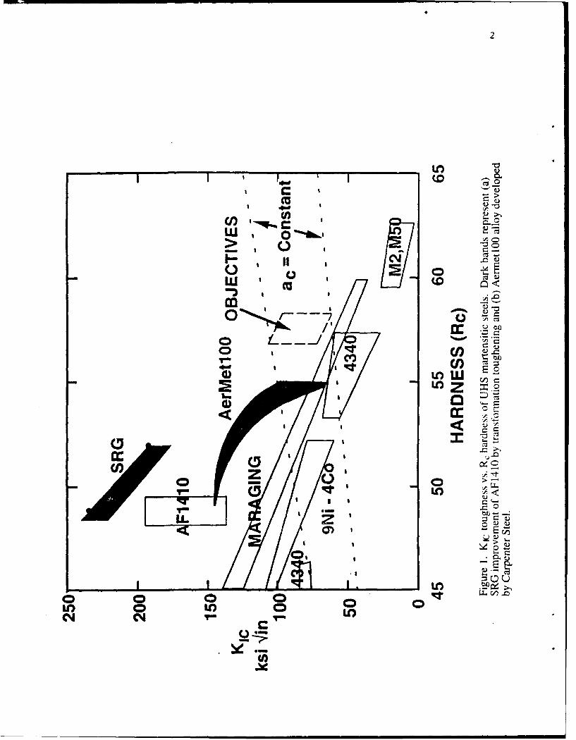
This program has addressed improving the fracture toughness of ultrahigh
strength (UHS) steels while maintaining a usable hardness level of approximately RC 57.
Property objectives are compared with existing alloys in Figure 1. Our approach to
enhancing fracture toughness in these martensitic steels included (1) transformation
toughening from controlled stability dispersed austenite precipitated during tempering.
(2) optimization of grain-refining dispersions for resistance to microvoid nucleation, and
(3) controlling the M2C carbide precipitation strengthening to eliminate competing
phases and achieve the required strength level at minimum carbon content.
Although the design approach consists of balancing and optimizing a number of
quantities, it can be divided into two basic areas. The first concerns the determination of
the most appropriate combination of Ni and Co to optimize three variables: the
martensitic transformation temperature (Ms), the stability of precipitated austenite, and a
toughening efficiency parameter. The second concerns the identity and combination of
carbide formers to optimize the following variables: amount of carbide formers required
to completely dissolve cementite, the driying force for precipitation, the carbide
C UN
00 t7
CI)Cf 'clm )
wo 0
00
0 'I LO-Pc ý
0 0 0
C4 04m
3
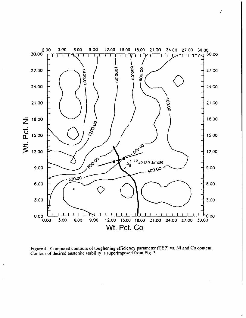
coarsening rate constant, and solution treatment temperature. The starting composition
for these calculations was a higher carbon modification of Aermet 100 (Carpenter Steel),
Fe- 13.5Co- 11 Ni-3Cr- 1.1 Mo-0.27C.
Using the THERMOCALC thermochemical database and software system and a
newly developed martensite kinetic model', an Ms contour plot was created as shown in
Figure 2. The Ms temperature of Aermet 100, 244°C, was used as a target for our design
and is drawn in the figure in bold.
Improved toughness can be obtained by the strain-induced transformation of
metastable austenite at a crack tip2 . This transformation-toughening mechanism can be
exploited by controlling the stability of precipitated austenite formed during tempering.
This stability is controlled primarily by the matrix content of Fe, Ni, and Co. The
optimum stability of austenite for a given composition can be theoretically determined by
computing the critical driving force required to transform an austenite particle to
martensite. Figure 3 is a contour plot for the computed chemical driving force of the
austenite to martensite transformation at room temperature for austenite precipitated at
500'C. This driving force is then used to determine the stability of the precipitated
austenite as a function of the Ni-Co compositions. The desired austenite stability for the
new alloy is that of Aermet 100 plus a factor, A(Ag), which compensates for the desired
higher strength level at our Rc 57 regime. The A(Ag) parameter was calculated using a
model developed by Haidemenopoulos 2 . and found to equal 235 J/mole. The Ag for the
Aermet 100 composition was found to be 1903.7 J/mole. Therefore, the optimum
stability of the precipitated austenite for the new alloy was chosen to be the sum, 2138.7
J/mole. This contour is highlighted in bold in Figure 3. The stability increases with Co
and Ni content.
An additional benefit of achieving a fine dispersion of metastable austenite is the
effect of transformation dilatation on toughness. Experimental results have shown that
there is a positive dependence of transformation toughening efficiency on the volume

4
o 0
0 6
0In C
I~
0
0)0 0
Iin=
0)iC4 a
(1N *10 IM)

5
0.00 3.00 6.00 9.00 12.00 15.00 18.00 21.00 24.00 27.00 30.0050.00 T--30.00
27.00 27.O0
24.00 24.00
21i.00 21.00
18.00 "0o00 18.00
O 15.00 15.00
S12.00 12.00
9 .30 9.003 00o. 0
00
3.00 'o0 3.00
0.00 0.000.00 3.00 6.00 9.00 12.00 15.00 18.00 21.00 24.00 27.00 30.00
Wt. Pct: Co
Figure 3. Computed contours of precipitated austenite stability represented by martensitictransformation driving force at room temperature (J/mole).

6
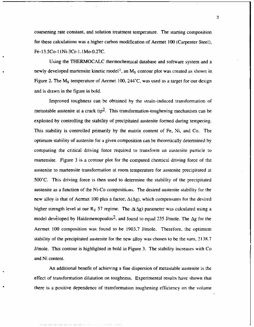
change to the third power 3 . We therefore define a toughening efficiency parameter
(TEP) as the product of two quantities:
TEP = fy x (AV/V) 3
fY = the volume fraction of precipitated metastable austenite.
AV/V = volume change
A model for the composition dependence of AV/V has been developed by Kuehmann 4
for compositions containing Fe. Ni, Cr, and Co and has been employed to predict the
TEP. Figure 4 is a contour plot of TEP versus weight percent Ni and Co. Three
compositions were chosen by cross-referencing Figures 2, 3. and 4. The Ms temperature
contour representing the 244°C line in Figure 2 was compared to the austenite stability
diagram, Figure 3, where the 2,138 J/mole isopleth was identified. These two lines were
transferred to the toughening diagram, Figure 4. Using these variables as guidelines, the
most appropriate Ni-Co composition was chosen, 13.5Co-10.6Ni (henceforth referred to
as MTL2). Two other constant M, compositions were chosen +/- I wt. pct. Co on either
side of the primary composition, alloy MTLI at 12.5Co-10.2Ni and alloy MTL3 at
14.5Co- lO.9Ni. These compositions are marked on Figure 4.
The second area of the design concerns optimization of the carbide formers. The
precipitation of metastable coherent M2C carbide from ferrite improves strength via
secondary hardening and improves toughness by dissolution of metastable cementite 3 .
However, precipitation of M2C must be completed without the nucleation of more stable
carbides, (M6C, M23C6, and M7C3) which will decrease toughness 3 . Completion of the
reaction 2M+C-->M2C is required todissolve all of the transient Fe3C carbides. Thus.
the mole fraction of the carbide formers must be at least equal to twice the mole fraction
of carbon, i.e. Xo+Xcr+Xv > 2XC. In addition, it is important to minimize the final
carbide size in order to maximize the strength. The final carbide size is determined by
the initial critical nucleus size which is inversely related to the precipitation
thermodynamic driving force as described by the Langer-Schwartz theory of precipitation
7
0.00 3.00 6.00 9.00 12.00 15.00 18.00 21.00 24-.00 27.00 30.0030.00 •"-- _ 30.00
"27.00 27.00o -
0 0 0 00 0 (0
24.00 0 Ki24.00
21.00 21.00
18.00 18.00
15.00 / 15.00
S12.00 _ 12.00
9.00 A Ag 2139 J/mole 90
6.00 6.00
3.00 3.00
0.00 0.000.00 3.00 6.00 9.00 12.00 15.00 18.00 21.00 24.00 27.00 30.00
Wt. Pct. Co
Figure 4. Computed contours of toughening efficiency parameter (TEP) vs. Ni and Co content.Contour of desired austenite stability is superimposed from Fig. 3.
8
from highly supersaturated solid solutions 5 . Thus, to minimize the final carbide size the
precipitation driving force must be maximized. Included with this optimization is the
coarsening rate constant which influences the overall rate of precipitation of the carbides.
It is desirable to ma.dmize this parameter by designing the kinetic competition so that
carbide precipitation can be driven to completion before impurity segregation to the grain
boundaries can occur. Finally, it is important to limit the content of carbide formers to
maintain an acceptable solution temperature.
Our previous work has demonstrated a beneficial effect of V in enhancing the
M2C precipitation driving force 3 . Looking initially at the effect of such V addition, we
balance the competing benefits and trade-offs of the solution temperature, precipitation
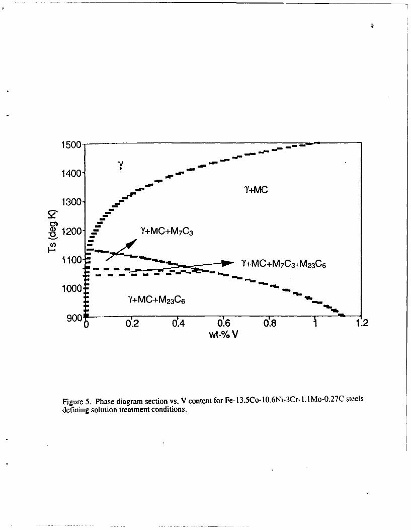
driving force, and the coarsening rate constant Kc. Figure 5 illustrates a phase diagram
section for alloy MTL2 for 0 to I wt. pct. V addition. This diagram remains essentially
unchanged for alloys MTL I and MTL3. The temperature required to put all components
into solution in austenite rises sharply with small amounts of V. The Ts reaches 1000'C
with the addition of just -0.12 wt. pct. V, suggesting a limit of 0.1 wt. pct. V should be
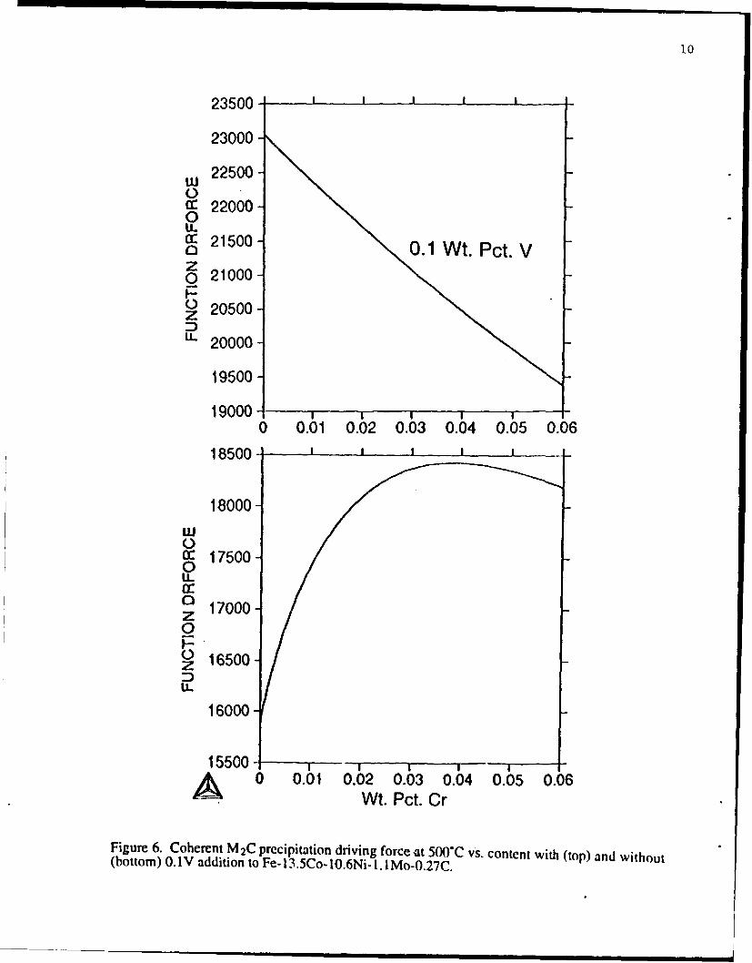
considered. THERMOCALC was used with a coherent M2C model 3 to calculate the
driving force for coherent M2C carbide precipitation for all three compositions with and
without 0. 1 wt. pct. V, for increasing Cr. The results of these calculations are plotted in
Figure 6. Without V, the driving force plot shows an optimum Cr level of 3-4 wt. pct. Cr.
With the V addition the driving force increases several thousand J/mole and decreases
linearly with increasing Cr. Addition of V was, therefore, justified by a substantial
increase in driving force for carbide precipitation. The Cr level was maintained at 3 wt.
pct. to allow full dissolution of cementite during M2 C precipitation. The Ms
temperatures were recalculated for inclusion of V and found to change insignificantly.
In addition to maximizing the precipitation driving force, it is desirable to
maximize the coarsening rate constant, Kc in order to minimize the degree of impurity
9
1500 O --a--
dma
1400 " ',, ""ar Id o
1400 Y+MC
1300
1200 " Y+MC+M 7C3
1100 N Y+MC+M 7 C 3 +M 2 3 C 6
1000 o "" wY+MC+M 23C6 ,,w
900 m -0 0.2 04 06 08 1.2
wt-% V
Figure 5. Phase diagram section vs. V content for Fe-13.5Co-10.6Ni-3Cr-I.IMo-0.27C steelsdefining solution treatment conditions.
10
23500-
23000
u 22500-Cc 22000-0U- S21500-21000.1 Wt. Pct. Vz0 21000-
O 20500-
u- 20000-
19500 -
19000-0 0.01 0.02 0.03 0.04 0.05 0.06
18500 _t-
18000
a: 17500
1 17000-0
z 16500DIL
16000
15500- -A 0 0.01 0.02 0.03 0.04 0.05 0.06Wt. Pct. Cr
Figure 6. Coherent M2C precipitation driving force -at 500"C vs. content with (top) and without(bottom) 0. 1 V addition to Fe- 13.5Co- 10.6Ni- I. 1 Mo-0.27C.

11
segregation to grain boundaries during secondary hardening. From Figure 7 it can be
seen that Kc increases in an approximately linear fashion with increasing Cr, without V.
However, the addition of V causes Kc to drop one third its original value for the 3Cr
alloys. This compromise is judged acceptable.
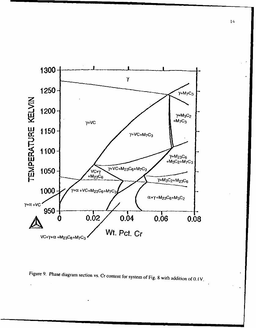
The final step in the design of this prototype steel was to check the effect of Cr on
solution treatment temperature, which we wish to maintain below 1000'C (1273K). This
was accomplished by computing phase diagram isopleths with respect to Cr, with and
without 0. IV. Figure 8 shows that without V, the solution temperature increases strongly
with Cr content. Figure 9 shows that the addition of 0. IV increases the solution
temperature to just below 1273K, slightly decreasing with Cr content. The Cr-Mo levels
were then maintained at the initial values of 3Cr- 1. 1 Mo.
Based on the optimization of the design variables as described above, three
prototype alloys were ordered:
MTL 1: 12.5Co- 10.2Ni-3Cr- 1.1Mo-0. IV-0.27C
MTL2: 13.5Co- 10.6Ni-3Cr- 1.1Mo-0. IV-0.27C
MTL3: 14.5Co- 10.9Ni-3Cr- 1.1Mo-O. IV-0.27C.
To control impurities and grain-refining dispersions, Ti deoxidation and late rare-earth
additions of La were specified. This is based on our previous identification 3 of Ti-based
MC carbides as the best grain-refining dispersion in terms of resistance to microvoid
nucleation, and La as an effective S getter in the absence of Mn. The alloys were
prepared as 50 lb.VIM melts by Precision Castparts Corporation of Portland, Oregon.
Melts were cast as 5" X 2" rectangular slabs, annealed at 675°C/16 hr., the hot top
removed, and were grit blasted and spot ground. The slabs were shipped to Niagara
Specialty Metals for hot rolling to 1/4" plate. The alloys were received with the
following compositions:

12
Coarsening Rate Constant, Kc1 3.5Co- 1 0.55NW1. .1 Mo-0.27C
1.764-
1.564-
1.364-
1.164-
< 0.964-
oE 0.764-
0.564-+0.364Pc.
0.164-
0 1 2 7wt-% Cr
Figure 7. Computed M 2 C coarsening rate constant at 500*C vs. Cr content with and withoutoA.Iv

13
1250- I I
z 1200- 7
yU' 1150- Y+M7c3
w11Y+M 2 3 C6 +M6 C:•1100-
I-lw
1050-- Y+M23 C6 Y+M7C3+M 2 3C6S~Y+M6C
Y+a+M 6C 1000 ( Yya+M2c6 Y+a+M 23C6+M7C3
95 1I iI I I +
0 0.01 0.02 0.03 0.04 0.05 0.06
Wt. Pct. Cr
Y+x+M 2 3 C 6 +M6C
Figure 8. Phase diagram section vs. Cr content for Fe-13.5Co-lO.6Ni-1.1 Mo-0.27C.
14
1250- /MC
1200 Y+M3C2
7+vc +M7C3
W 1150 VCM3
1000- y~ VC+M23 06 C+M 23C63 7
VC+,y+a +M 2 3 06 +M 7 C3 WtPc.C
Figure 9. Phase diagram section Vs. Cr content for system of Fig. 8 with addition of 0. 1 V,
15
MTL I: 12.46Co- 10.08Ni-2.92Cr- 1.05Mo-0.095V-0.2 IC
MTL2: 13.45Co- 10.59Ni-2.97Cr- 1.15Mo-0.113V-0.30C
MTL3: 14.36Co- 10.75Ni-2.94Cr- 1.07Mo-O.IV-0.30C
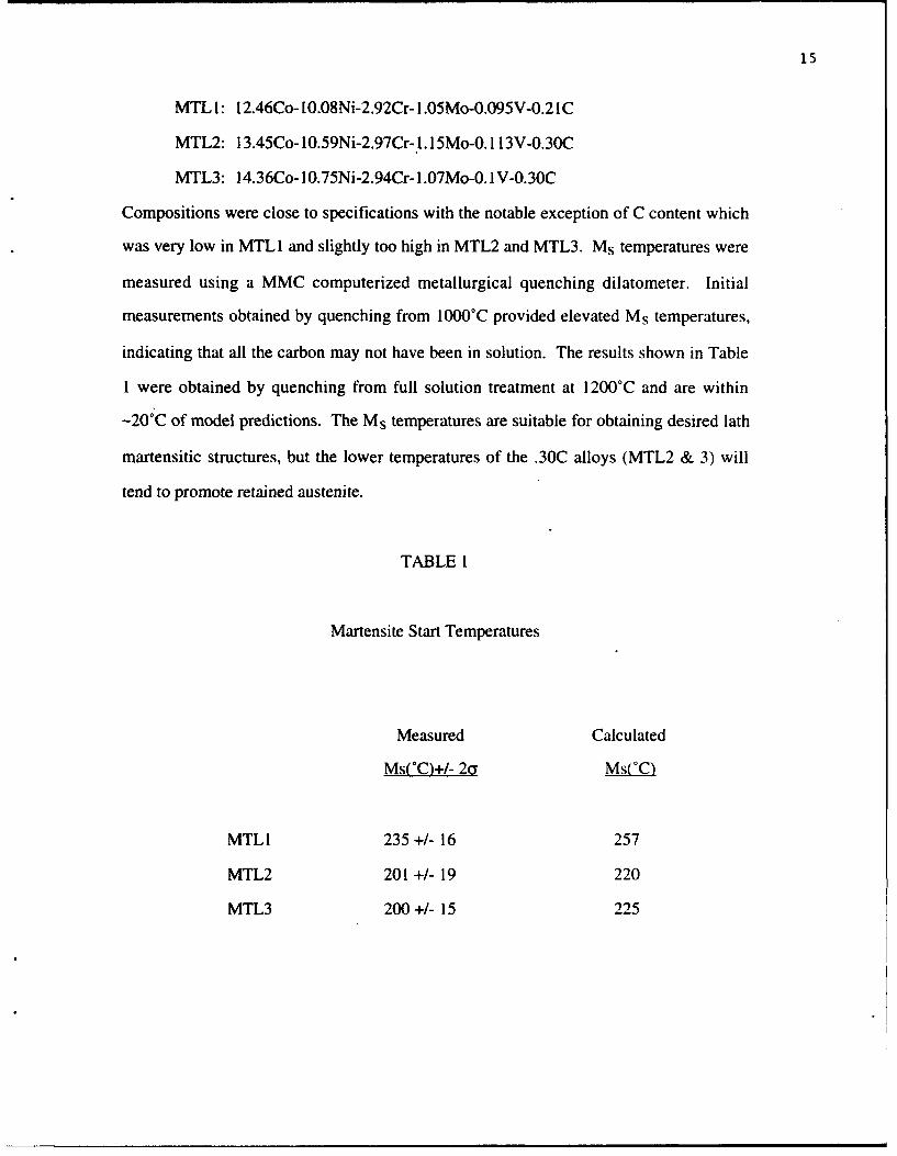
Compositions were close to specifications with the notable exception of C content which
was very low in MTL I and slightly too high in MTL2 and MTL3. Ms temperatures were
measured using a MMC computerized metallurgical quenching dilatometer. Initial
measurements obtained by quenching from 1000°C provided elevated Ms temperatures,
indicating that all the carbon may not have been in solution. The results shown in Table
1 were obtained by quenching from full solution treatment at 1200°C and are within
-20'C of model predictions. The Ms temperatures are suitable for obtaining desired lath
martensitic structures, but the lower temperatures of the .30C alloys (MTL2 & 3) will
tend to promote retained austenite.
TABLE 1
Martensite Start Temperatures
Measured Calculated
Ms(*C)+/- 2a Ms(*C)
MTLI 235 +/- 16 257
MTL2 201 +/- 19 220
MTL3 200+/- 15 225

16
TESTING AND ANALYSIS
Central to our approach for enhancing fracture toughness in these martensitic
steels is maintaining control of the M2C carbide precipitation strengthening dispersion to
eliminate competing carbide phases (and achieve a high strength level at minimum
carbon content) while maintaining a fine MC carbide grain-refining dispersion during
solution treatment. To assess the success of this approach in these alloys, TEM
extraction replicas were made from alloy MTL3 to determine the distribution of
undissolved carbides in size and composition. Two samples from alloy MTL3, one
solution treated for 1 hr. at 1000°C and the other at I 100°C, and each tempered at 482°C
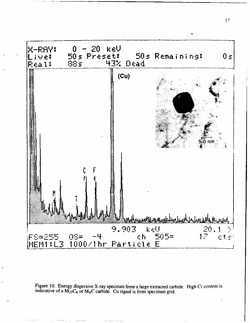
for 10 hr. were replicated and examined by analytical electron microscopy. The larger
carbides, on the order of 75nm in diameter, were infrequent and maintained compositions
similar to those of the Xray fluorescence spectrum of Figure 10. These larger carbides
were always Cr-rich, indicating an M23C6 (or possibly M6C) carbide. The smaller
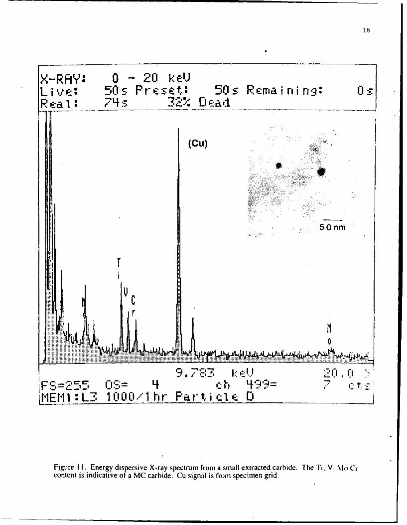
carbides, on the order of 20nm in diameter, were much more frequent and maintained
compositions similar to those in Figures II and 12. These compositions are indicative of
the desired Ti-rich MC carbide. Although the larger carbides were apparent in the
extraction replicas, their relative scarcity compared with the much more abundant small
carbides indicates the dissolution of the coarse M23C6 carbides was essentially complete
during solution treatment. This leaves only the fine MC carbides as the microvoid-
nucleation-resistant grain-refining dispersion 3.
KIC fracture toughness tests were conducted in accordance with ASTM
designation E399, "Standard Test Method for Plane Strain Fracture Toughness of
Metallic Materials." Oversized blanks were wire-cut from plate, heat treated, then ground
to the final 10mm x 5mm size. The fatigue crack starter notch was wire-cut after
grinding so that the final crack plane orientation was L-S. Samples were pre-cracked in
fatigue by loading in three-point bending. Plots of load vs. displacement were recorded
1.7
X-RAY: 0 - 20 k eVL ive: 50s Preset.: 50s Remaining9:ORe a: 88 S 3 Da
(Cu)
5,0 nm
C F
rAMT
I EMi1 L3 1 OCI'''1 hr- Par t i ql E
Figure 10. Energy dispersive X-ray spectrum from a large e'xtracted carbide. High Cr content isindicative of a M23C6 or M6C carbide. Cu signal is from specimen grid.
18
X-RAY: 0 - 20 keVLi v e: 50s Preset: 50s Remai ni OZq:-R'eal: 74 - :_-,'2' f,, e-_ ad,_
(Cu)
5Onm
t Cr
i! l 0
"" . .......:: c . .. .I ..'. I I.".
CIS 4h 4 *-,,-FM __"-•= 0.; - ,'- i 'i'= . ,_
1E P1 L3. 1' .0001 hr Part. i cl e D
Figure Ii. Energy dispersive X-ray spectrum from a small extracted carbide. The Ti, V, ,lo Crcontent is indicative of a MC carbide. Cu signal is from specimen grid.

19
X-RAY: 0 -20 keVLive: 50s Preset: 100s Remaini ng: 50sR ;-a I : 60 s 17-0 D' ad
1C
.~~~ ~~ -
............... .........
r
M
FV 2h '9:-,= 7 ,iHE1 : L3 110I' 0 C:.. 1 Hr 1CI Hrs -:
Figure 12. Energy dispersive X-ray spectrum from a small extracted carbide. The Ti, Mo, Crcontent is indicative of a MC carbide.

20
for samples loaded to failure, and constructions were performed to calculate KQ and to
establish the validity of the KIC measurement. To minimize cost, one sample was tested
for each quoted KIC measurement.
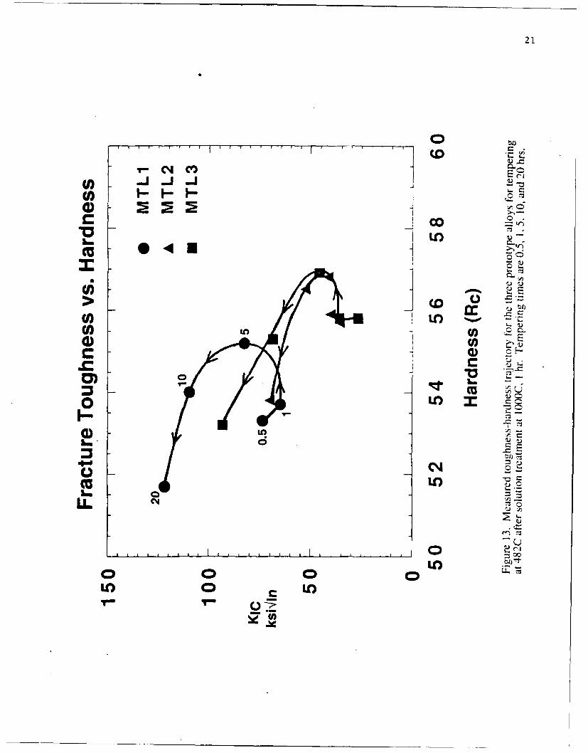
Figure 13 shows KIC fracture toughness for alloys MTL I, MTL2 and MTL3 as a
function of hardness after solution treatment at 1000'C for 1 hour and tempering for 0.5,
1, 5, 10 and 20 hr. at 4820C. The curve shapes suggest an optimal tempering time of -8
hr. for the best strength/toughness combination, associated with near completion of
cementite dissolution. Alloy MTLI was fully solution treated at the 1000oC solution
temperature as indicated by its high toughness; however, the lower carbon content, 0.21
weight percent compared to 0.30 for alloys MTL2 and MTL3, restricts its hardness to a
maximum of RC 55.2. The higher carbon content in the other two alloys prevented
complete solution treatment at 1000'C. The solution treatment study for alloys MTL2
and MTL3 was therefore extended to higher temperatures.
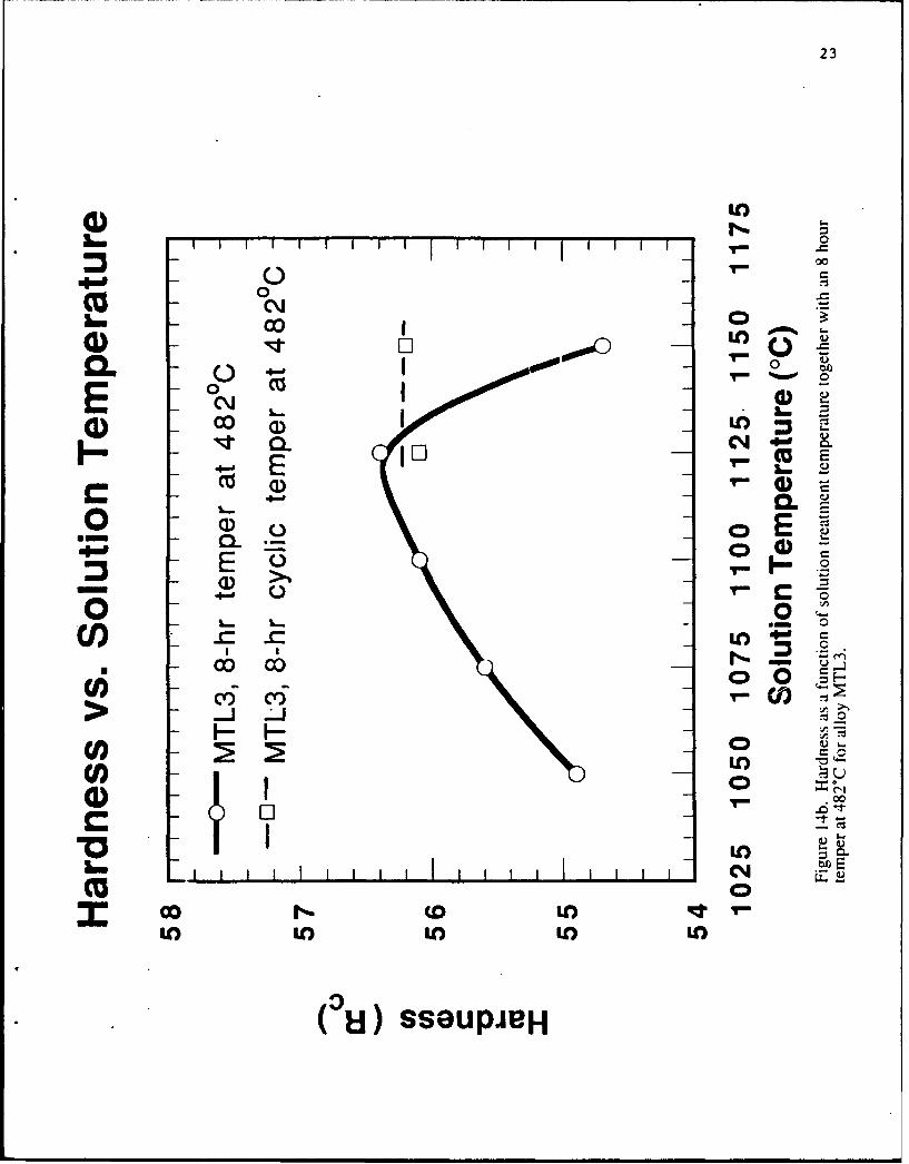
The effects of increasing solution treatment temperature together with an 8 hr.
temper at 4820C on secondary hardening for alloys MTL2 and MTL3 are shown in
Figures 14a and 14b, respectively. Here it can be seen that a hardness of RC 56.2 is
attained for MTL2 at a solution treatment of I 100oC for I hr. Likewise, alloy MTL3
reaches a hardness peak of RC 56.4 at a solution treatment of 1 125'C for I hr. The
decreased hardness for higher solution temperatures is attributed to excessive retained
austenite content. This is supported by an observed hardening effect of cyclic tempering
with liquid nitrogen cooling. For solution treatment at 1100 to I 150C. saturation
magnetization measurements indicate that the austenite content of MTL3 is 12-1 5pct after
a conventional 8hr temper, and is reduced to 8-9pct by the cyclic tempering
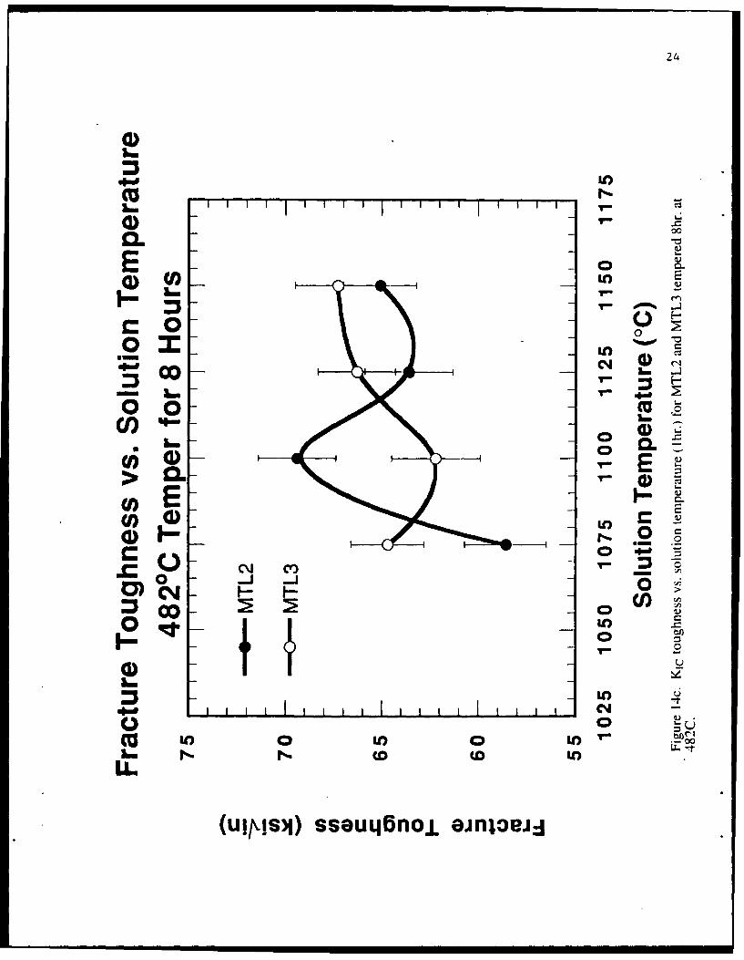
Fracture toughness as a function of solution temperature for an 8 hr. temper at
4820C for alloys MTL2 and MTL3 are shown in Figure 14c. Peak toughness for alloy
MTL2 is 69.4 ksiqlin attained at a solution treatment of I 100oC for I hr. while MTL3
21
r- C4 M
C -
1.. I 1
07
Lin C) C
0) 0
a) If) -
Lf)I Lf

22
00C, , ci
E oo 00
w o ECl) R 2 VE6 (6
LO
I oE o
LO-
Lm I..' 0 )
m co to f) L4T T
&& oo LoLO
-J-J cnJB-
23
4) 1L 00
00
CL 00 0
a) EOL
EE(E
CL00
.- I C.)r
Cl)D
(I=
CC
(Ui) SSGUPJRH
24
00
Lun
- n T- 4.
o0-0
~(I)
.2'.2
COW£00 'L
CJ Le) y-.)w0
U..
(ui~s~j)ssoul~njL ;jnlte£0
25
reaches 66.3 ksi•in at 1 125°C for 1 hr. Preliminary measurements using cyclic tempering
on toughness at higher solution treatment temperatures shows no advantage in toughness.
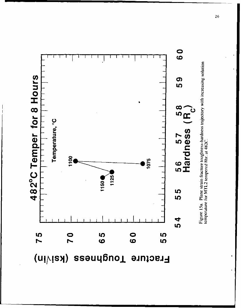
A summary of the solution treatment study for alloys MTL2 and MTL3 is shown
in Figures 15a and 15b, plotting fracture toughness/hardness combinations for increasing
solution treatment temperatures, employing an 8 hr. temper at 482*C. Solution treatment
condition TS2 represents the optimum heat treatment for alloy MTL2 (RC 56.2 at 69.4
ksilin) in Figure 15a, while condition TS3 in Figure 15b is the optimum heat treatment
for alloy MTL3 (RC 56.4 at 66.3 ksi•in). It is important to point out that this
combination of high hardness and toughness was achieved without the benefits of
transformation toughening that could be achievable with multi-step tempering in these
compositions.
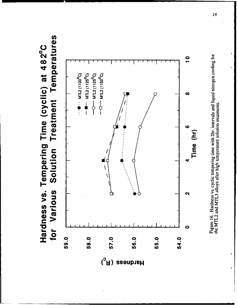
The hardness for MTL2 and MTL3 as a function of tempering time for cyclic
tempering at 482°C for different solution treatment temperatures is shown in Figure 16.
It is apparent that our 8 hr. temper is past peak hardness and represents the over-aged
condition for both alloys MTL2 and MTL3. This condition is optimal for toughness,
through dissolution of cementite by near-completion of M2C alloy carbide precipitation.
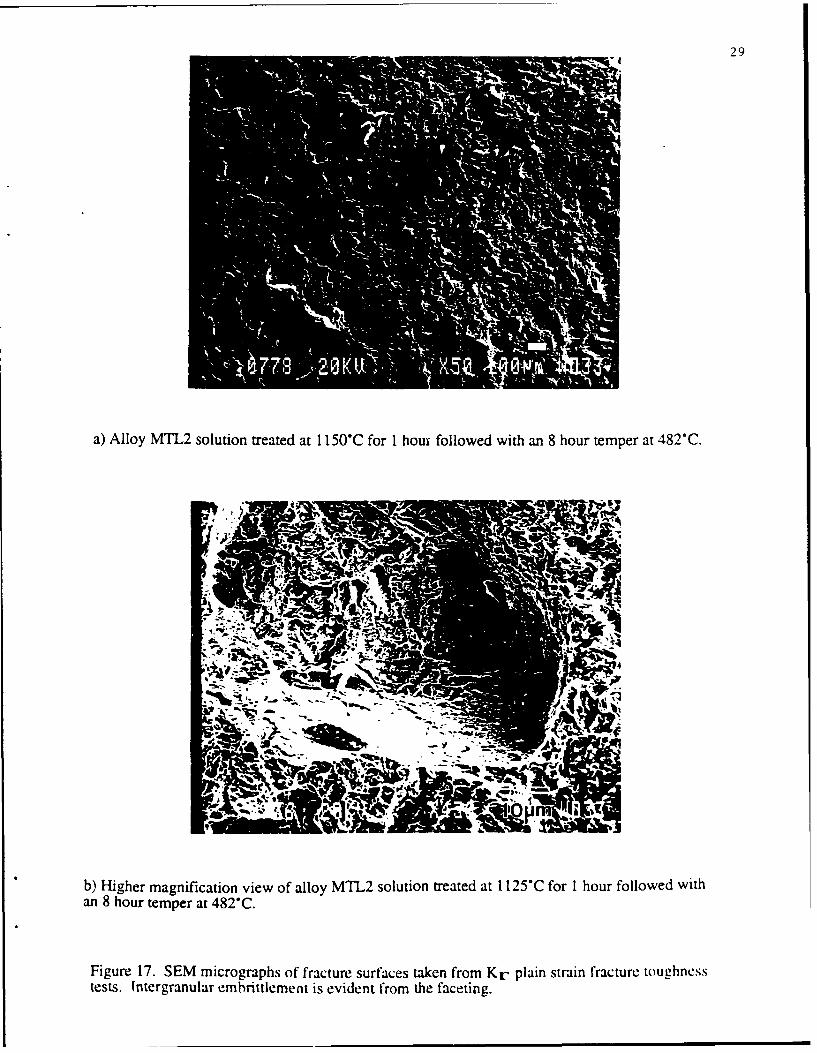
It is important to further note, that as solution treatment temperatures are
increased, the alloys MTL2 and MTL3 begin to exhibit partial (-10%) intergranular
fracture. Figure 17a-b are SEM micrographs of fracture surfaces taken from the KIC
plane strain fracture toughness tests. It is apparent from the faceting evident in the
micrographs that some intergranular embrittlement has occurred. This may limit
toughness under ballistic impact conditions, and could be improved in future heats by
boron additions, to enhance grain boundary cohesion3 .
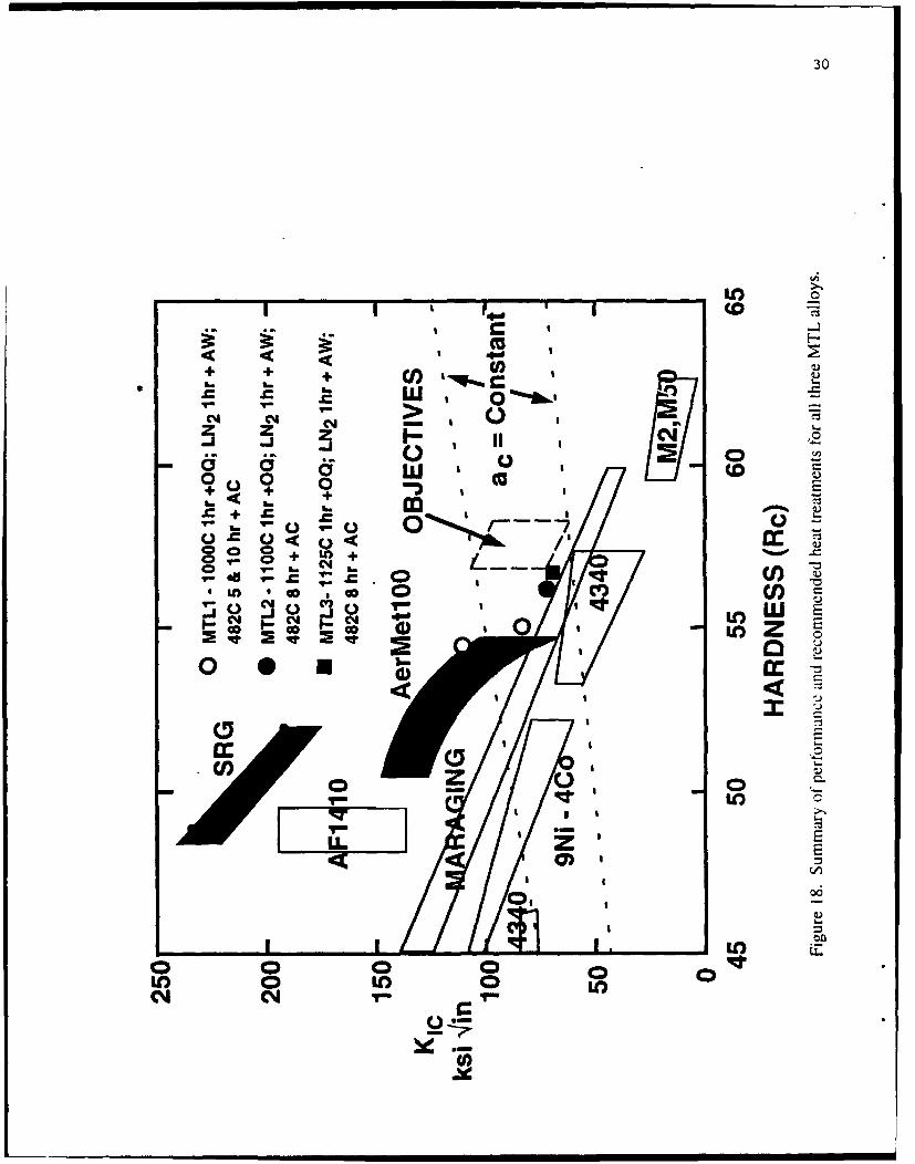
Figure 18 summarizes our recommended heat treatments for all three MTL alloys
and compares their performance with our objectives on a plot of fracture toughness
versus hardness. Although the property objectives are nearly attained, it is apparent that
reducing the carbon content from 0.30 to 0.25 weight percent in alloys MTL2 and MTL3
26
00
Coo
co o0
LM L
a) 11)4)
C?0.
E E "a) __ _____ ___Lm
0 NqN
co LOIt
LO)
ICO 0 I) 0 I)r*-_ (o CD I)
(uiplsj) sseuqj~noL ainjoe~i.

27
00 LO
E00
cm *
C) _O
(u h.M ssutBnj 10njei
28
CM)
It I I I I .I I I I I• I I I I
000000
o -- -, - 0
0" 0 0- 0E
a)V
LowL
oo , 0 C/ mIIa
Won H' --
• 'r o o o o
o) UO U), U) U) U"
(u) sseuPJeH
29
a) Alloy MTL2 solution treated at 1150"C for 1 houx followed with an 8 hour temper at 482°C.
A..
b) Higher magnification view of alloy MTL2 solution treated at 1125"C for 1 hour followed withan 8 hour temper at 482°C.
Figure 17. SEM micrographs of fracture surfaces taken from Kr plain strain fracture toughnesstests. (ntergranular embrittlement is evident from the faceting.
30
U) 0
+ + 0 l)0 .qY~rmmC + wo
Cl Cl -
z zr I I
0o o wo LI o gi
0) 0 CC
z E
ton
71
J9

31
would increase toughness by reducing the solution treatment temperature and increase
hardness by reducing retained austenite. Although the high solution temperatures
required for MTL2 and 3 may promote quench cracking, the properties so far
demonstrated appear worthy of ballistic testing. We thus recommend heat treatment of
the available remaining plate material according to the conditions specified in Figure 18
for ballistic V,0 measurements at ARL.
FURTHER DESIGN CALCULATIONS
The properties shown in Figure 18 demonstrate that the MTLI composition
matches the properties of Aermet 100 with only 0.2 1C compared to 0.24±.0 1C for the
latter. This supports the predicted effectiveness of V in refining carbide size for
strengthening efficiency. It is based on this result that we estimate that 0.25C should be
sufficient to achieve the desired Rc57 hardness, provided the M, temperature is kept
sufficiently high (>2200C) to avoid excessive retained austenite.
Results of the first prototypes suggest that achieving our toughness objectives will
require precipitated austenite transformation toughening which has not yet been
demonstrated in the prototype alloys. Our further design calculations have addressed the
further enhancement of transformation toughening potential.
The contour plot of toughening efficiency parameter (TEP) in Figure 4 suggests a
desirable region in the upper left which is not accessible with Ni-Co variations alone due
to M, temperature limitations. The transformation dilatation model indicates that the
additional degree of freedom necessary to access this level of TEP is best provided by
variations in Cr content. Accordingly, Figure 19 plots the levels of austenite stability
achievable in 3Cr and 4Cr modifications of MTL2 with Ni and Co adjusted to maintain
an M. temperature of 220C. The level of interest is denoted by that for the AFI410 steel
where transformation toughening has been successfully demonstrated 2 . For the same
alloys, Figure 20 plots the behavior of precipitated austenite fraction, transformation
dilatation, and the toughness efficiency parameter (TEP). While the increased Cr level

32
Austenite StabilityEffect of Increasing Cr
4400-
4200
""4000-0) 3Cr03800
S3600
- 3400"
3200 AF1-41
3000 -
10 10.5 11 1 .5 12 12.5 1'3 13.5 14 14.5 15wt-% Co
Figure 19. Stability of precipitated vs. wt. pcL Co. For 1. IMo-o.27C-0. I V, studying the effectof increasing Cr from 3% to 4%.

Fraction Austenite 33Effect of Increasing Cr
0.0
.4-
.2-
010 16.5 11 11.5 112 0.5 13 13.5 414. 1wt-%Co
EFfeof Increasing Cr
5- 4Cr
I.-
f 1o 6.5 fl i115 f2 0~.5 13 15. 1'4- TM 15wt-% co
Fiur 2. reipTatdaseiefatotasomto iaain noughnessg efficiencyPa me rparameer (TP) fo allo comostin of Fnraig. 19.

34
slightly decreases the austenite fraction, the dilatation is significantly increased such that
the TEP is increased by a factor of 3. The phase diagram section of Figure 9 indicates
that increasing Cr to this level causes no increase in solution temperature. Figure 7
indicates a negligible change in rate constant, and Figure 6 indicates a slight decrease in
M2C precipitation driving force. The higher Cr might, however, increase the stability of
transient cementite.
Recent transformation toughening experiments 4 on Aermet 100 indicate that the
faster M2 C precipitation kinetics in this alloy causes too much strength loss during
austenite precipitation. Hence exploitation of precipitated austenite transformation
toughening in the prototype armor steels may require slower carbide precipitation
kinetics. This should be controllable through the predicted coarsening rate constant.
However, slower tempering response would promote further impurity segregation at
interfaces, tending to further promote intergranular fracture. It is anticipated-that full
exploitation of the transformation toughening potential of these alloys will require
independent control of intergranular cohesion through gettering of embrittling impurities
and addition of cohesion enhancers such as the boron mentioned earlier.
CONCLUSIONS AND RECOMMENDATIONS
Despite the problems associated with carbon contents outside of the
specifications, the first prototype armor steels demonstrate the effectiveness of small V
additions in achieving desired strength levels. With optimal solution treatments, 8 hr.
tempering at 482°C gives strength/toughness combinations worthy of ballistic V.50 tests
on the remaining plate material. Optimal 1 hr. solution temperatures are 1000°C for
MTLI, 1 100°C for MTL2 and ! 125°C for MTL3. The KIC toughness of 69.4 ksNin. at
R,56.2 hardness may well be sufficient to resist plate shattering during ballistic impact,
thus exploiting the greater ballistic performance potential of this hardness level.

35
Further design calculations suggest the potential for substantial transformation
toughening in further modifications of these alloys, provided austenite and carbide
precipitation kinetics can be suitably matched to avoid excessive softening, and
intergranular cohesion can be suitably controlled.

36
REFERENCES
1. G. Ghosh and G. B. Olson, Proc. Intl. Conf. Martensitic Transformations
(ICOMAT-92), Monterey CA, July 19-24, 1992, in press.
2. G. N. Haidemenopoulos, G. B. Olson, and M. Cohen, "Dispersed-Phase
Transformation Toughening in UHS Steels," in Innovations in Ultrahigh-Strength
Steel Technology, eds. G. B. Olson, M. Azrin and E. S. Wright, Sagamore Army
Materials Research Conf. Proc.: 34th (1990) 549-593.
3. G. B. Olson, "Overview: Science of Steel," in Innovations in Ultrahigh-Strength
Steel Technology, eds. G. B. Olson, M. Azrin and E. S. Wright, Sagamore Army
Materials Research Conf. Proc.: 34th (1990) 3-66.
4. C. J. Kuehmann, doctoral research in progress, Dept. Materials Science and Eng.,
Northwestern University, Evanston IL.
5. R. Wagner and R. Kampmann, "Solid State Precipitation at High
Supersaturations", in Innovations in Ultrahigh-Strength Steel Technology, eds. G.
B. Olson, M. Azrin and E. S. Wright, Sagamore Army Materials Research Conf.
Proc.: 34th (1990) 209-222; J. S. Langer and A. J. Schwartz, Phys. Rev. A21
(1980) 948.
AIPENDE M
PROCESSING OF PROTOTYPE ARMOR STEELS

NORTHWESTERN UNIVERSITYEVANSTON. ILLINOIS 60208-3116
Sma REsEARCH GRoup TEL" HONE (708) 491-2847MATERIALS RESEARCH CENTER FAX No.: (708) 491-78202145 SHERIDAN ROAD
October 4, 1991
Dr. Xuan Nguyen-DinhPrecision Cast Parts Corporation4600 Southeast Harney DrivePortland, OR 97206
Dear Dr. Nguyen-Dinh:
Following our phone conversation of November 8, 1991, the compositions of the 50 lb.VIM steel melts we wouldike to obtain are (wt. pct., bal. Fe):
C Q Ni QQ Mo Y
MILl 0.27 12.5 10.0 3.0 1.10 0.10
MTL2 0.27 13.5 10.4 3.0 1.10 0.10
MTI3 0.27 14.5 10.6 3.0 1.10 0.10
We would like the melts prepared from ultrahigh purity materials, keeping Mn and Si at <.01, andP and S at -. 001. Carpenter Steel is willing to contribute the high purity Fe (pharmaceutical grade"atomiron") if necessary. We would like the melts Ti deoxidized (final Ti .015 max) followed byLa additions balanced to the P and S levels.
The melts should be cast as 5" x 2" slab, annealed at 125017-16h, the hot top removed,followed by grit blasting and spot grinding. The slabs would then be shipped to Niagara SpecialtyMetals for hot rolling to 1/4" plate.
Depending on the cost, we may prefer to prepare MTL2 before the other two. Please giveme an estimate at your earliest convenience, as we are anxious to prepare material for evaluation ina student Senior Project.
Please call me if you need further information.
Sincerely yours,
Gregory B. Olson
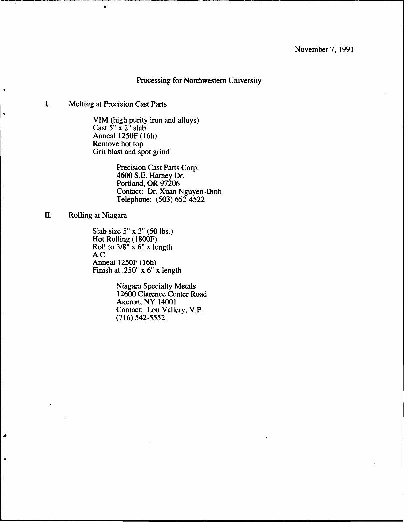
November 7, 1991
Processing for Northwestern University
Melting at Precision Cast Parts
VIM (high purity iron and alloys)Cast 5" x 2" slabAnneal 1250F (16h)Remove hot topGrit blast and spot grind
Precision Cast Parts Corp.4600 S.E. Harney Dr.Portland, OR 97206Contact: Dr. Xuan Nguyen-DinhTelephone: (503) 652-4522
IL Rolling at Niagara
Slab size 5" x 2" (50 lbs.)Hot Rolling (1800F)Roll to 3/8" x 6" x lengthA.C.Anneal 1250F (16h)Finish at .250" x 6" x length
Niagara Specialty Metals12600 Clarence Center RoadAkeron, NY 14001Contact: Lou Vallery, V.P.(716) 542-5552

Heat Chemical Analysis (wt. pct.)
MTL1 MTL2 MTL3
C 0.210 0.300 0.300
Co 12.46 13.45 14.36
Ni 10.08 10.59 10.75
Cr 2.92 2.97 2.94
Mo 1.05 1.15 1.07
V 0.095 0.113 0.10
Ti 0.0142 0.013 0.01
Al 0.001 0.001 0.001
Mn 0.04 0.04 0.04
Si 0.02 0.03
Cu 0.01 0.01 0.01
Cb 0.01 0.01 0.01
Ta 0.01 0.01 0.01
Sn 0.001 0.001
P 0.001 0.001
S 0.0001 <.001 <.001
N2 0.0001 0.0003 0.0003
02 0.0038 0.0028 0.0010
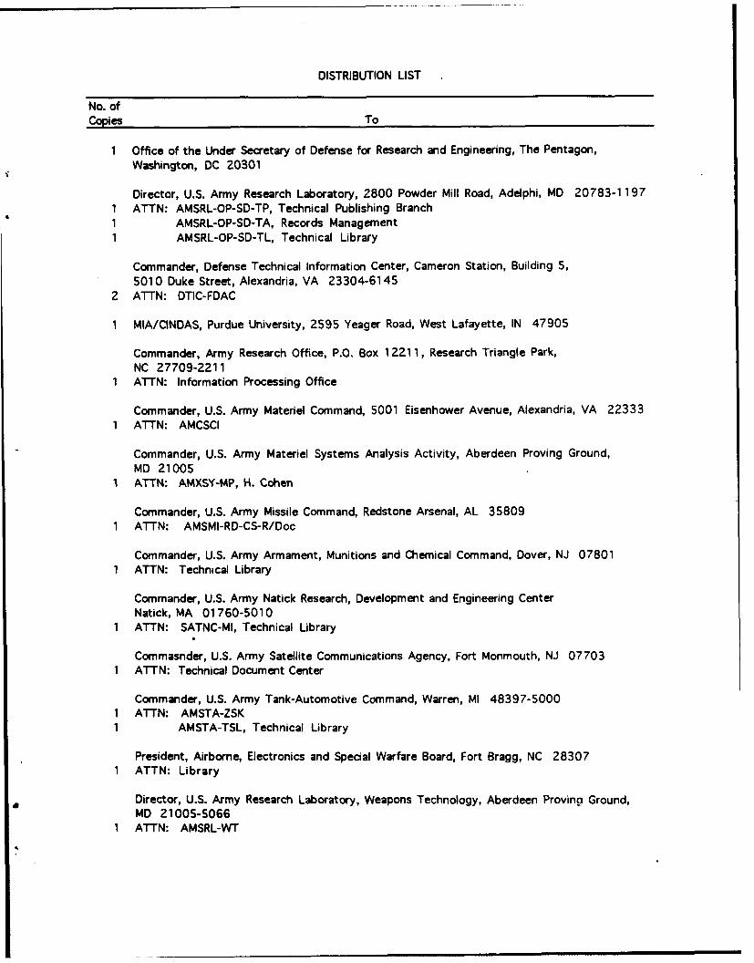
DISTRIBUTION LIST
No. ofCopies To
1 Office of the Under Secretary of Defense for Research and Engineering, The Pentagon,Washington, DC 20301
Director, U.S. Army Research Laboratory, 2800 Powder Mill Road, Adeiphi, MD 20783-11971 ATTN: AMSRL-OP-SD-TP, Technical Publishing Branch1 AMSRL-OP-SD-TA, Records Management1 AMSRL-OP-SD-TL, Technical Library
Commander, Defense Technical Information Center, Cameron Station, Building 5,5010 Duke Street, Alexandria, VA 23304-6145
2 ATTN: DTIC-FDAC
1 MIA/CINDAS, Purdue University, 2595 Yeager Road, West Lafayette, IN 47905
Commander, Army Research Office, P.O. Box 12211, Research Triangle Park,NC 27709-2211
1 ATTN: Information Processing Office
Commander, U.S. Army Materiel Command, 5001 Eisenhower Avenue, Alexandria, VA 223331 ATTN: AMCSCI
Commander, U.S. Army Materiel Systems Analysis Activity, Aberdeen Proving Ground,MD 21005
I ATTN: AMXSY-MP, H. Cohen
Commander, U.S. Army Missile Command, Redstone Arsenal, AL 358091 ATTN: AMSMI-RD-CS-R/Doc
Commander, U.S. Army Armament, Munitions and Chemical Command, Dover, NJ 078011 ATTN: Technical Library
Commander, U.S. Army Natick Research, Development and Engineering CenterNatick, MA 01760-5010
1 ATTN: SATNC-MI, Technical Library
Commasnder, U.S. Army Satellite Communications Agency, Fort Monmouth, NJ 077031 ATTN: Technical Document Center
Commander, U.S. Army Tank-Automotive Command, Warren, MI 48397-50001 ATTN: AMSTA-ZSK1 AMSTA-TSL, Technical Library
President, Airborne, Electronics and Special Warfare Board, Fort Bragg, NC 283071 ATTN: Library
Director, U.S. Army Research Laboratory, Weapons Technology, Aberdeen Proving Ground,MD 21005-5066
1 ATTN: AMSRL-WTI"

No. ofCopies To
Commander, Dugway Proving Ground, UT 840221 ATTN: Technical Library, Technical Information Division
Commander, U.S. Army Research Laboratory, 2800 Powder Mill Road, Adelphi, MD 207831 ATTN: AMSRL-SS
Director, Benet Weapons Laboratory, LCWSL, USA AMCCOM, Watervliet, NY 121 891 ATTN: AMSMC-LCB-TL1 AMSMC-LCB-R1 AMSMC-LCB-RM1 AMSMC-LCB-RP
Commander, U.S. Army Foreign Science and Technology Center, 220 7th Street, N.E.,Charlottesville, VA 22901-5396
3 ATTN: AIFRTC, Applied Technologies Branch, Gerald Schlesinger
Commander, U.S. Army Aeromedical Research Unit, P.O. Box 577, Fort Rucker, AL 363601 ATTN: Technical Library
U.S. Army Aviation Training Library, Fort Rucker, AL 363601 ATTN: Building 5906-5907
Commander, U.S. Army Agency for Aviation Safety, Fort Rucker, AL 36361 ATTN: Technical Library
Commander, Clarke Engineer School Library, 3202 Nebraska Ave., N., Fort Leonard Wood,MO 65473-5000
1 ATTN: Library
Commander, U.S. Army Engineer Waterways Experiment Station, P.O. Box 631, Vicksburg,MS 39180
1 ATTN: Research Center Library
Commandant, U.S. Army Quartermaster School, Fort Lee, VA 238011 ATTN: Quartermaster School Library
Naval Research Laboratory, Washington, DC 203751 ATTN: Code 6384
Chief of Naval Research, Arlington, VA 222171 ATTN: Code 471
Commander, U.S. Air Force Wright Research and Development Center, Wright-PattersonAir Force Base, OH 45433-6523
1 ATTN: WRDC/MLLP, M. Forney, Jr.1 WRDC/MLBC, Mr. Stanley Schulman
., , . ! !
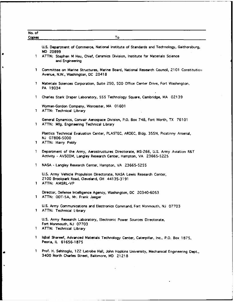
No. ofCopies To
U.S. Department of Commerce, National Institute of Standards and Technology, Gaithersburg,MD 20899
1 ATTN: Stephen M Hsu, Chief, Ceramics Division, Institute for Materials Scienceand Engineering
1 Committee on Marine Structures, Marine Board, National Research Council, 2101 ConstitutioiAvenue, N.W., Washington, DC 2041 8
1 Materials Sciences Corporation, Suite 250, 500 Office Center Drive, Fort Washington,
PA 19034
1 Charles Stark Draper Laboratory, 555 Technology Square, Cambridge, MA 02139
Wyman-Gordon Company, Worcester, MA 016011 ATTN: Technical Library
General Dynamics, Convair Aerospace Division, P.O. Box 748, Fort Worth, TX 761011 ATTN: Mfg. Engineering Technical Library
Plastics Technical Evaluation Center, PLASTEC, ARDEC, Bldg. 355N, Picatinny Arsenal,NJ 07806-5000
1 ATTN: Harry Pebly
1 Department of the Army, Aerostructures Directorate, MS-266, U.S. Army Aviation R&TActivity - AVSCOM, Langley Research Center, Hampton, VA 23665-5225
1 NASA - Langley Research Center, Hampton, VA 23665-5255
U.S. Army Vehicle Propulsion Directorate, NASA Lewis Research Center,2100 Brookpark Road, Cleveland, OH 441 35-31 91
1 ATTN: AMSRL-VP
Director, Defense Intelligence Agency, Washington, DC 20340-60531 ATTN: ODT-5A, Mr. Frank Jaeger
U.S. Army Communications and Electronics Command, Fort Monmouth, NJ 077031 ATTN: Technical Library
U.S. Army Research Laboratory, Electronic Power Sources Directorate,Fort Monmouth, NJ 07703
1 ATTN: Technical Library
1 lqbal Shareef, Advanced Materials Technology Center, Caterpillar, Inc., P.O. Box 1 875,Peoria, IL 61656-1875
1 Prof. H. Sehitoglu, 122 Latrobe Hall, John Hopkins University, Mechanical Engineering Dept.,3400 North Charles Street, Baltimore, MD 21218

No. ofCopies To
1 Dr. John Vitek, Oak Ridge National Laboratory, Bldg. 5500, MS 6376, P.O. Box 2008,Oak Ridge, TN 37831-6376
5 Prof. Gregory B. Olson, Materials Science and Engineering, 2030 Technological Institute,Northwestern University, Evanston, IL 60208-3108
Director, U.S. Army Research Laboratory, Watertown, MA 021 72-00012 ATTN: AMSRL-OP-WT-IS, Technical Library1 AMSRL-OP-WT-IS, Visual Information Branch1 AMSRL-PR-WT, Procurement
30 AMSRL-MA-CC, Morris Azrin COR
S