Embed Size (px)
Citation preview
Design of a Vertical–Axis Wind Turbine Phase II 7 March 2014
Group 11 - MUN VAWT Design Jonathan Clarke Luke Hancox Daniel MacKenzie Matthew Whelan
i Design of a Vertical-Axis Wind Turbine – Phase II 7 March 2014
ABSTRACT This report details Phase II of the vertical-axis wind turbine design conducted by MUN VAWT
Design. Included are information about the applicable regulations and standards to be followed in
the design process, a discussion of aerodynamic modelling, details on the preliminary structural
design, an overview of environmental concerns, and a preliminary economic analysis.
ii Design of a Vertical-Axis Wind Turbine – Phase II 7 March 2014
ACKNOWLEDGMENTS
We would like to thank Dr. Sam Nakhla for his help and guidance.
iii Design of a Vertical-Axis Wind Turbine – Phase II 7 March 2014
CONTENTS
Abstract ......................................................................................................................................................................................... i
Acknowledgments ................................................................................................................................................................... ii
List of Figures & Tables ........................................................................................................................................................ iv
1 Introduction ..................................................................................................................................................................... 1
2 Regulations ....................................................................................................................................................................... 1
2.1 General ...................................................................................................................................................................... 1
2.2 Classes ....................................................................................................................................................................... 2
2.3 Design Load Cases ................................................................................................................................................ 2
3 Aerodynamics .................................................................................................................................................................. 4
3.1 Preliminary Sizing ................................................................................................................................................ 4
3.2 Preliminary Analysis ........................................................................................................................................... 4
3.3 The Double-Multiple Streamtube Model .................................................................................................... 4
3.4 Turbine Evaluation .............................................................................................................................................. 5
3.5 Aerodynamic Results .......................................................................................................................................... 6
4 Structural Design ........................................................................................................................................................... 8
4.1 Material Selection................................................................................................................................................. 9
4.2 Turbine Blades .................................................................................................................................................... 10
4.3 Driveshaft .............................................................................................................................................................. 12
4.3.1 Driveshaft – Results ................................................................................................................................. 13
4.4 Driveshaft Components ................................................................................................................................... 13
4.4.1 Bearings ........................................................................................................................................................ 13
4.4.2 Mechanical Couplings ............................................................................................................................. 14
4.5 Tower ...................................................................................................................................................................... 14
4.5.1 Tower – Axial Stress ................................................................................................................................ 16
4.5.2 Tower – Shear Stress ............................................................................................................................... 16
iv Design of a Vertical-Axis Wind Turbine – Phase II 7 March 2014
4.5.3 Tower – Bending ....................................................................................................................................... 17
4.5.4 Tower – Von Mises Stresses ................................................................................................................. 17
4.5.5 Tower – Results ......................................................................................................................................... 18
5 Environment .................................................................................................................................................................. 18
6 Preliminary Economic Analysis ............................................................................................................................. 18
7 Progress Report ............................................................................................................................................................ 19
8 Conclusion ....................................................................................................................................................................... 21
Appendix A: Abbreviations used in IEC 61400-1 ......................................................................................................... I
Appendix B: Airfoil Bending Moment Calculations ................................................................................................... II
Appendix C: Gantt Chart ..................................................................................................................................................... III
Bibliography ............................................................................................................................................................................. IV
LIST OF FIGURES & TABLES Figure 1: Discretization of VAWT for DMS method ................................................................................................... 5
Figure 2: Power Coefficient vs. Tip-Speed Ratio for Various Aspect Ratios.................................................... 6
Figure 3: Raw and corrected power coefficient curve ............................................................................................. 6
Figure 4: Turbine Power Curve ......................................................................................................................................... 7
Figure 5: Rotor Torque Curve ............................................................................................................................................ 8
Figure 6: Aerodynamic loading on turbine blades .................................................................................................. 10
Figure 7: Plot of DU06-W200 airfoil .............................................................................................................................. 11
Figure 8: Free-Body Diagram of Tower ........................................................................................................................ 15
Figure 9: Status of Phase II tasks..................................................................................................................................... 20
Figure 10: Status of Phase III tasks ................................................................................................................................ 20
Table 1: Basic parameters for wind turbine classes ................................................................................................. 2
Table 2: Design Load Cases ................................................................................................................................................. 2
Table 3: Turbine Parameters .............................................................................................................................................. 5
Table 4: Component size estimate for unlimited and governed turbines ........................................................ 7
Table 5: Mechanical properties of A35 structural steel ......................................................................................... 10
Table 6: Mechanical properties of AISI 4340 steel .................................................................................................. 10
Table 7: Key economic estimates .................................................................................................................................... 19
1 Design of a Vertical-Axis Wind Turbine – Phase II 7 March 2014
1 INTRODUCTION In the province of Newfoundland and Labrador, many remote communities must rely on diesel
generators to meet their power requirements. With the rising cost of fuel and transportation,
alternatives to total reliance on diesel for electricity generation are becoming attractive. To this
end, MUN VAWT Design will design a vertical-axis wind turbine (VAWT) for operation in remote
communities in Newfoundland and Labrador.
The design will:
Work in conjunction with diesel generators, not replace them Be robust and simplistic Produce sufficient energy to offset diesel fuel costs Allow for transportation by boat to remote areas
Based on research conducted for the first design report, a 3-bladed H-rotor configuration with
DU06-W200 airfoils was selected as the preliminary VAWT design. This report will elaborate on
this design through aerodynamic and structural analyses, relevant regulations, environmental
effects, and a cost-benefit analysis.
2 REGULATIONS
2.1 General After completion of Phase I research into sizing and weather patterns, the standards and
regulations that govern wind turbines were consulted. The standard chosen to consult was IEC
61400-1 titled Wind turbines – Part 1: Design Requirements, developed by the International
Electrotechnical Commission (IEC). The IEC is a worldwide organization for the standardization of
all electrical, electronic and related technologies. The goal of the IEC is to “promote international
co-operation on all questions concerning standardization in the electrical and electronics fields.”
The purpose of this section of the IEC 61400 is to specify the minimum design requirements for
wind turbines in order to ensure the engineering integrity of the turbine. It is not intended to be
used as a complete specification or instruction manual but to provide the engineering and technical
requirements to guarantee the safety of the structural, mechanical, electrical, and control systems.
The standard can be used for any size wind turbine but is not intended for the design of offshore
turbines; small wind turbines are also subject to IEC 61400-2.
This standard covers all subsystems of the turbine including: control systems, protection
mechanisms, internal electrical systems, mechanical systems and support structures. Also, the
standard should be used in conjunction with other applicable standards where appropriate.
Although the standard is concerned with requirements that apply to the design, manufacture,
installation and manuals for operation and maintenance of a wind turbine and the associated
2 Design of a Vertical-Axis Wind Turbine – Phase II 7 March 2014
quality management process the area of concern for the project is the design requirements set out
in the standard. [1]
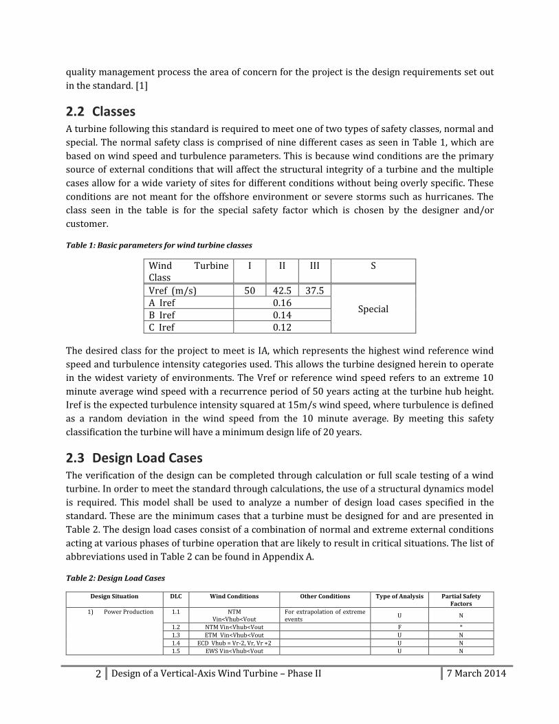
2.2 Classes A turbine following this standard is required to meet one of two types of safety classes, normal and
special. The normal safety class is comprised of nine different cases as seen in Table 1, which are
based on wind speed and turbulence parameters. This is because wind conditions are the primary
source of external conditions that will affect the structural integrity of a turbine and the multiple
cases allow for a wide variety of sites for different conditions without being overly specific. These
conditions are not meant for the offshore environment or severe storms such as hurricanes. The
class seen in the table is for the special safety factor which is chosen by the designer and/or
customer.
Table 1: Basic parameters for wind turbine classes
Wind Turbine Class
I II III S
Vref (m/s) 50 42.5 37.5
Special A Iref 0.16 B Iref 0.14 C Iref 0.12
The desired class for the project to meet is IA, which represents the highest wind reference wind
speed and turbulence intensity categories used. This allows the turbine designed herein to operate
in the widest variety of environments. The Vref or reference wind speed refers to an extreme 10
minute average wind speed with a recurrence period of 50 years acting at the turbine hub height.
Iref is the expected turbulence intensity squared at 15m/s wind speed, where turbulence is defined
as a random deviation in the wind speed from the 10 minute average. By meeting this safety
classification the turbine will have a minimum design life of 20 years.
2.3 Design Load Cases The verification of the design can be completed through calculation or full scale testing of a wind
turbine. In order to meet the standard through calculations, the use of a structural dynamics model
is required. This model shall be used to analyze a number of design load cases specified in the
standard. These are the minimum cases that a turbine must be designed for and are presented in
Table 2. The design load cases consist of a combination of normal and extreme external conditions
acting at various phases of turbine operation that are likely to result in critical situations. The list of
abbreviations used in Table 2 can be found in Appendix A.
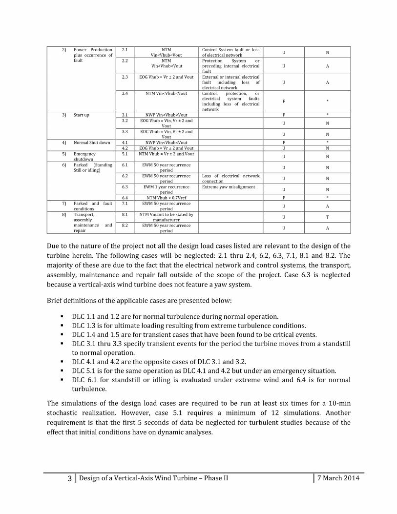
Table 2: Design Load Cases
Design Situation DLC Wind Conditions Other Conditions Type of Analysis Partial Safety Factors
1) Power Production 1.1 NTM Vin<Vhub<Vout
For extrapolation of extreme events
U N
1.2 NTM Vin<Vhub<Vout F *
1.3 ETM Vin<Vhub<Vout U N
1.4 ECD Vhub = Vr-2, Vr, Vr +2 U N 1.5 EWS Vin<Vhub<Vout U N
3 Design of a Vertical-Axis Wind Turbine – Phase II 7 March 2014
2) Power Production plus occurrence of fault
2.1 NTM Vin<Vhub<Vout
Control System fault or loss of electrical network
U N
2.2 NTM Vin<Vhub<Vout
Protection System or preceding internal electrical fault
U A
2.3 EOG Vhub = Vr ± 2 and Vout External or internal electrical fault including loss of electrical network
U A
2.4 NTM Vin<Vhub<Vout Control, protection, or electrical system faults including loss of electrical network
F *
3) Start up 3.1 NWP Vin<Vhub<Vout F *
3.2 EOG Vhub = Vin, Vr ± 2 and Vout
U N
3.3 EDC Vhub = Vin, Vr ± 2 and Vout
U N
4) Normal Shut down 4.1 NWP Vin<Vhub<Vout F * 4.2 EOG Vhub = Vr ± 2 and Vout U N
5) Emergency shutdown
5.1 NTM Vhub = Vr ± 2 and Vout U N
6) Parked (Standing Still or idling)
6.1 EWM 50 year recurrence period
U N
6.2 EWM 50 year recurrence period
Loss of electrical network connection
U N
6.3 EWM 1 year recurrence period
Extreme yaw misalignment U N
6.4 NTM Vhub < 0.7Vref F * 7) Parked and fault
conditions 7.1 EWM 50 year recurrence
period
U A
8) Transport, assembly maintenance and repair
8.1 NTM Vmaint to be stated by manufacturer
U T
8.2 EWM 50 year recurrence period
U A
Due to the nature of the project not all the design load cases listed are relevant to the design of the
turbine herein. The following cases will be neglected: 2.1 thru 2.4, 6.2, 6.3, 7.1, 8.1 and 8.2. The
majority of these are due to the fact that the electrical network and control systems, the transport,
assembly, maintenance and repair fall outside of the scope of the project. Case 6.3 is neglected
because a vertical-axis wind turbine does not feature a yaw system.
Brief definitions of the applicable cases are presented below:
DLC 1.1 and 1.2 are for normal turbulence during normal operation.
DLC 1.3 is for ultimate loading resulting from extreme turbulence conditions.
DLC 1.4 and 1.5 are for transient cases that have been found to be critical events.
DLC 3.1 thru 3.3 specify transient events for the period the turbine moves from a standstill
to normal operation.
DLC 4.1 and 4.2 are the opposite cases of DLC 3.1 and 3.2.
DLC 5.1 is for the same operation as DLC 4.1 and 4.2 but under an emergency situation.
DLC 6.1 for standstill or idling is evaluated under extreme wind and 6.4 is for normal
turbulence.
The simulations of the design load cases are required to be run at least six times for a 10-min
stochastic realization. However, case 5.1 requires a minimum of 12 simulations. Another
requirement is that the first 5 seconds of data be neglected for turbulent studies because of the
effect that initial conditions have on dynamic analyses.
4 Design of a Vertical-Axis Wind Turbine – Phase II 7 March 2014
3 AERODYNAMICS
3.1 Preliminary Sizing Preliminary sizing was conducted using the wind power density formula:
⁄
This formula allows for the calculation of power generated per square metre of turbine swept area
given average air density , power coefficient , and wind speed . Using an estimated power
coefficient of 0.4, preliminary sizing indicates that in order to develop the desired maximum output
power of 100kW at a wind speed of 10.5 m/s, the swept area of the turbine will need to be
approximately 320 m2.
3.2 Preliminary Analysis Preliminary aerodynamic analysis was conducted using QBlade, an open-source wind turbine
simulation software developed by a team at the Technical University of Berlin, Germany. The
software is integrated with the airfoil simulation code XFoil (developed by Mark Drela at the
Massachusetts Institute of Technology) to provide lift and drag polars for standard NACA airfoils
and extrapolate them to 360° angle-of-attack. Using these polars, QBlade can evaluate the
performance of a vertical-axis wind turbine using the double-multiple streamtube model.
3.3 The Double-Multiple Streamtube Model The double-multiple streamtube model (DMS model) for a vertical-axis wind turbine is an
algorithm that computes aerodynamic forces on the turbine blades, taking into account that the
blades pass through the flow stream twice. The blades are considered to absorb energy from the
flow once in the upstream side of turbine, and once in the downstream side.
Similar to the actuator disk theory, the DMS method applies conservation of momentum to the flow
impinging on the turbine. The swept area of the turbine is divided into two sets of elements
(streamtubes). For each of these streamtubes, momentum conservation is compared with the blade
forces computed from lift and drag coefficients at all azimuth angles. The upstream side is
evaluated separately from the downstream side, with the induced flow velocity at the exit of the
upwind streamtubes being used as the inflow for the downwind streamtubes. [2]
5 Design of a Vertical-Axis Wind Turbine – Phase II 7 March 2014
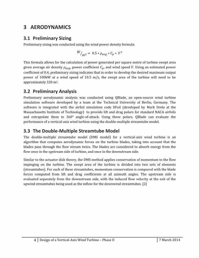
Figure 1: Discretization of VAWT for DMS method
Some limitations of this method identified by the software’s developers include convergence issues
for very high solidities and high tip-speed ratios. Since the turbine design is to have a moderate
solidity of approximately 0.35, the solidity limitation was not anticipated to cause any problems.
The limitation on tip-speed ratio was avoided by prescribing the wind speed and turbine rotational
speed for each simulation such that excessive tip-speed ratios were avoided. The software also
neglects the effects of the wake of the support tower, and cannot account for dynamic stall of the
turbine blades. Correction for these limitations is detailed in Section 3.5.
3.4 Turbine Evaluation To perform preliminary evaluation of the turbine, a simple H-rotor-style VAWT was designed in
QBlade with the specifications shown in Table 3. A variety of aspect ratios (ratio of blade height to
rotor diameter) were evaluated to determine the optimal configuration.
Table 3: Turbine Parameters
Configuration 1 2 3 Airfoil DU06-W200 DU06-W200 DU06-W200
No. of Blades 3 3 3 Blade Chord 1.6 metres 1.6 metres 1.6 metres Rotor Height 20 metres 17.9 metres 16 metres
Rotor Diameter 16 metres 17.9 metres 20 metres Aspect Ratio 1.25 : 1 1 : 1 1 : 1.25
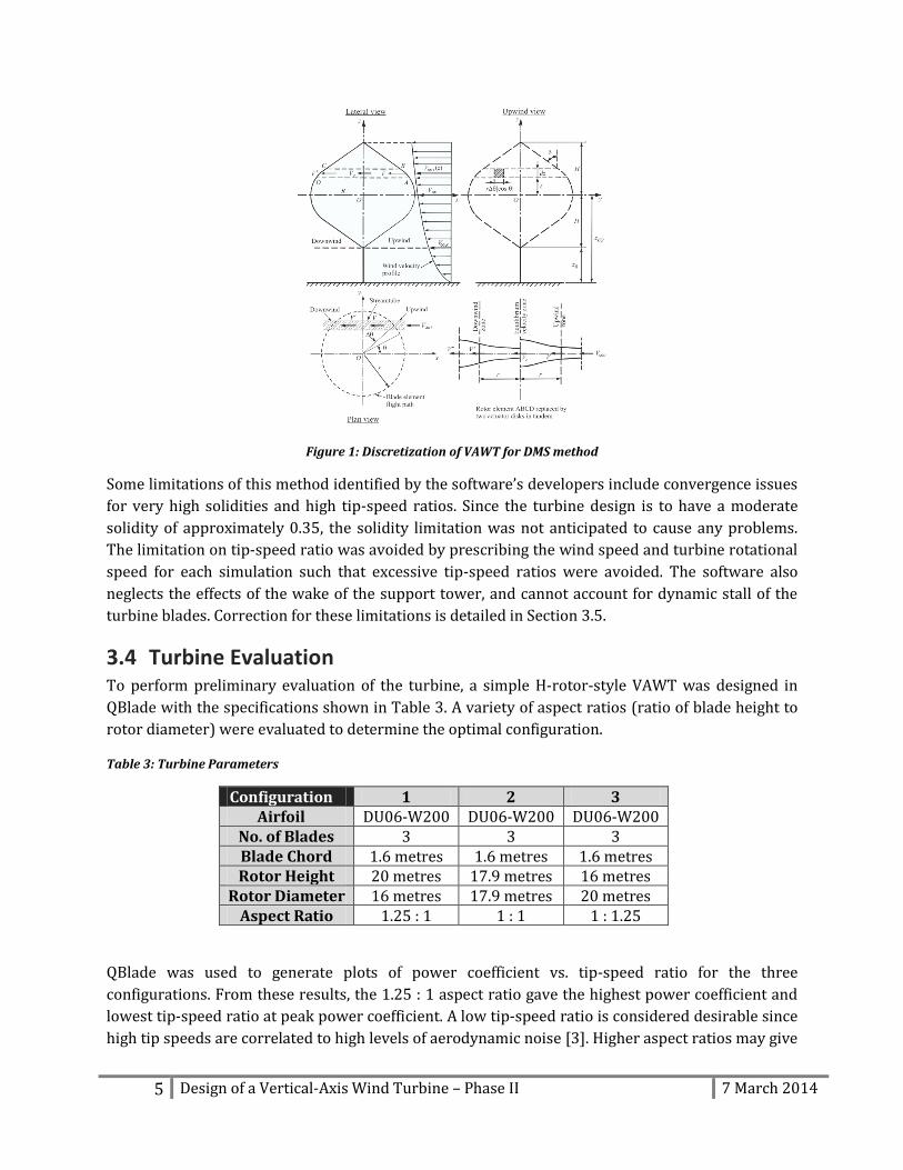
QBlade was used to generate plots of power coefficient vs. tip-speed ratio for the three
configurations. From these results, the 1.25 : 1 aspect ratio gave the highest power coefficient and
lowest tip-speed ratio at peak power coefficient. A low tip-speed ratio is considered desirable since
high tip speeds are correlated to high levels of aerodynamic noise [3]. Higher aspect ratios may give
6 Design of a Vertical-Axis Wind Turbine – Phase II 7 March 2014
higher power coefficients; however, it was decided to limit the height of the blades to 20 metres for
ease of shipping.
Figure 2: Power Coefficient vs. Tip-Speed Ratio for Various Aspect Ratios
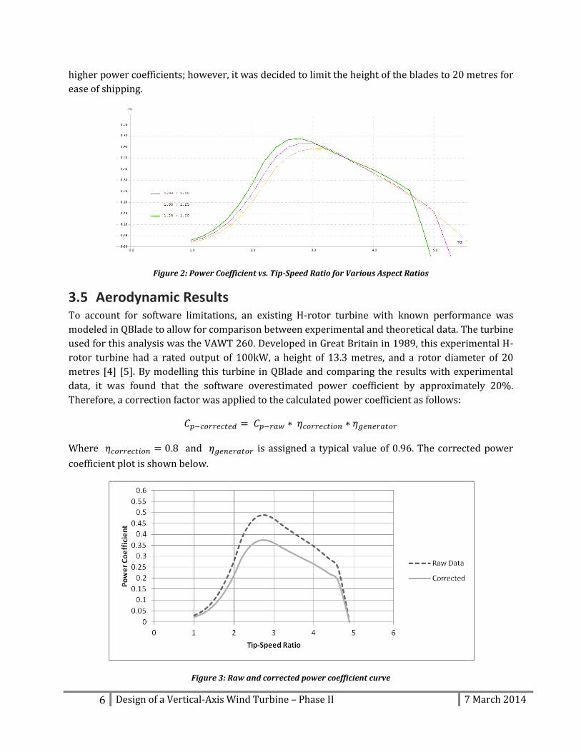
3.5 Aerodynamic Results To account for software limitations, an existing H-rotor turbine with known performance was
modeled in QBlade to allow for comparison between experimental and theoretical data. The turbine
used for this analysis was the VAWT 260. Developed in Great Britain in 1989, this experimental H-
rotor turbine had a rated output of 100kW, a height of 13.3 metres, and a rotor diameter of 20
metres [4] [5]. By modelling this turbine in QBlade and comparing the results with experimental
data, it was found that the software overestimated power coefficient by approximately 20%.
Therefore, a correction factor was applied to the calculated power coefficient as follows:
Where and is assigned a typical value of 0.96. The corrected power
coefficient plot is shown below.
Figure 3: Raw and corrected power coefficient curve
7 Design of a Vertical-Axis Wind Turbine – Phase II 7 March 2014
From the power coefficient plot, the best operating point for the turbine was determined to be at a
tip-speed ratio of 2.7.
The rotor was then modeled under wind speeds from 2 m/s to 35 m/s (the maximum sustained
wind recorded in the target area). The rotational speed of the turbine was allowed to vary to
maintain the optimal tip-speed ratio. Output power, rotor torque, and aerodynamic forces on the
entire rotor as well as the individual blades were recorded over this range. The rotor was also
analysed in a parked condition at a wind speed of 50 m/s to obtain the rotor loads at the IEC
61400-1 Class IA reference state.
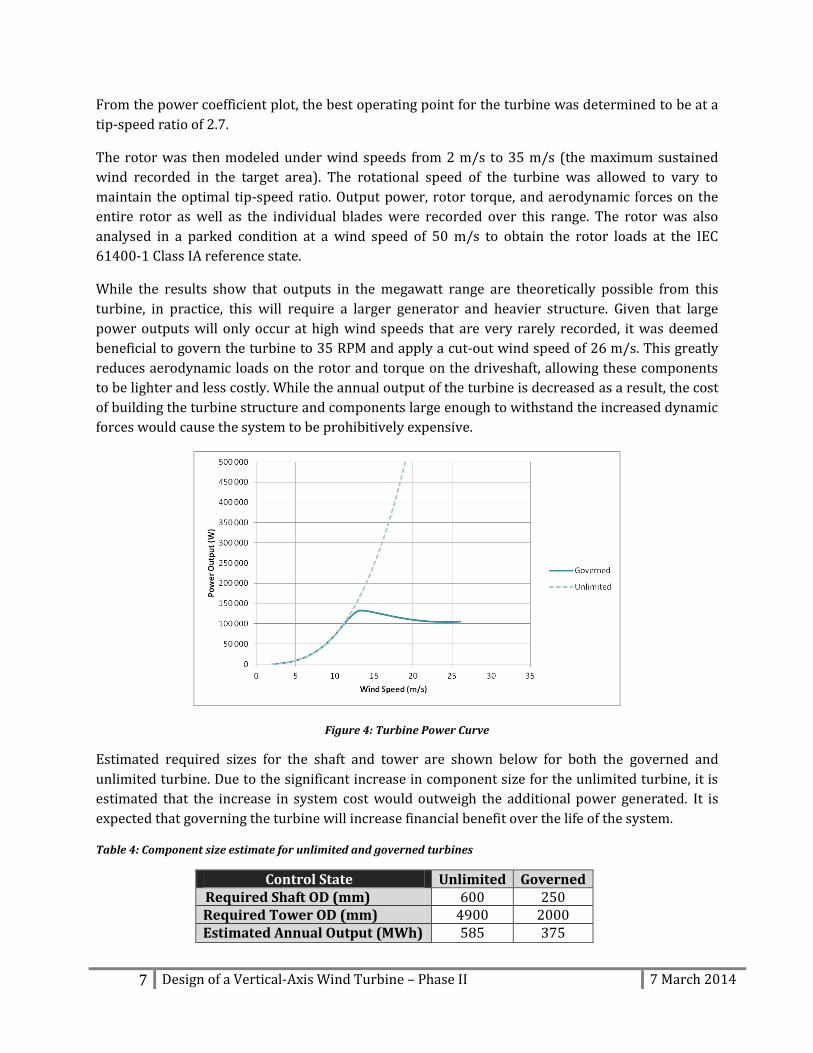
While the results show that outputs in the megawatt range are theoretically possible from this
turbine, in practice, this will require a larger generator and heavier structure. Given that large
power outputs will only occur at high wind speeds that are very rarely recorded, it was deemed
beneficial to govern the turbine to 35 RPM and apply a cut-out wind speed of 26 m/s. This greatly
reduces aerodynamic loads on the rotor and torque on the driveshaft, allowing these components
to be lighter and less costly. While the annual output of the turbine is decreased as a result, the cost
of building the turbine structure and components large enough to withstand the increased dynamic
forces would cause the system to be prohibitively expensive.
Figure 4: Turbine Power Curve
Estimated required sizes for the shaft and tower are shown below for both the governed and
unlimited turbine. Due to the significant increase in component size for the unlimited turbine, it is
estimated that the increase in system cost would outweigh the additional power generated. It is
expected that governing the turbine will increase financial benefit over the life of the system.
Table 4: Component size estimate for unlimited and governed turbines
Control State Unlimited Governed Required Shaft OD (mm) 600 250 Required Tower OD (mm) 4900 2000 Estimated Annual Output (MWh) 585 375
8 Design of a Vertical-Axis Wind Turbine – Phase II 7 March 2014
Methods for governing a wind turbine include: [6]
Active regulation: the pitch of the turbine blades is altered during operation to reduce
torque at high wind speeds. This method allows for higher aerodynamic efficiency, but is
more complex.
Passive regulation: The turbine blades are designed to stall at high wind speeds, reducing
lift and lowering the rotational torque. This method is simpler to implement than active
regulation, but often results in lower power coefficients.
Rheostatic braking: Excess generator current is routed through a network of resistors and
dissipated as heat, increasing generator torque for a given rotational speed. [7]
In order to brake the turbine above the cut-out wind speed, a combination of aerodynamic braking
and mechanical drum brakes are usually used. Mechanical brakes cannot usually be used alone
because of the large amount of heat generated in the process of stopping a turbine from full speed.
Braking and governing methods will be examined in more detail in the final phase of the project.
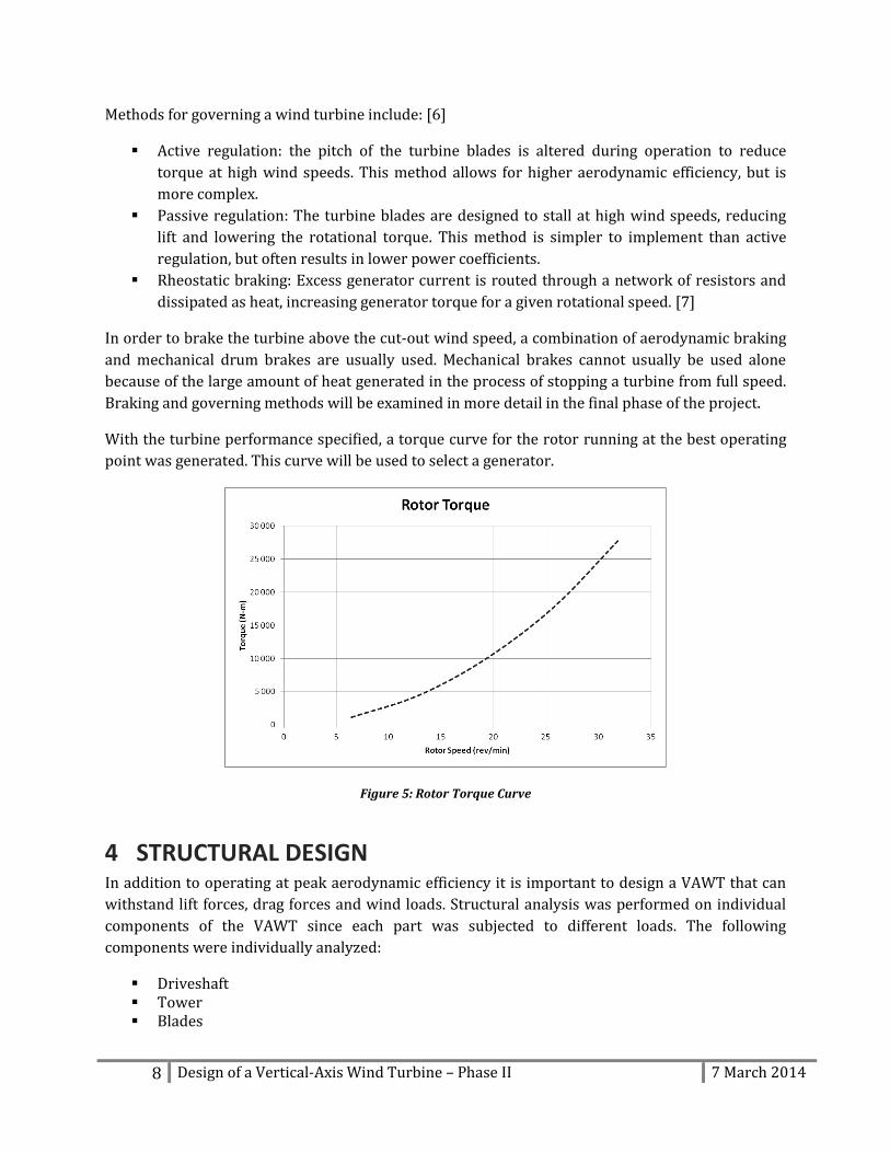
With the turbine performance specified, a torque curve for the rotor running at the best operating
point was generated. This curve will be used to select a generator.
Figure 5: Rotor Torque Curve
4 STRUCTURAL DESIGN In addition to operating at peak aerodynamic efficiency it is important to design a VAWT that can
withstand lift forces, drag forces and wind loads. Structural analysis was performed on individual
components of the VAWT since each part was subjected to different loads. The following
components were individually analyzed:
Driveshaft Tower Blades
9 Design of a Vertical-Axis Wind Turbine – Phase II 7 March 2014
For this section of the project, basic solid mechanics as well as bearing selection, manufacturing
constraints, maintenance, and transportation concerns were considered. The final report will cover
a more comprehensive structural analysis including finite element analysis (FEA), strut sizing,
vibration considerations, bolt design and/or weld types. Note that the numerical values calculated
in this section of the report are subject to change as the design is refined and more detailed
aerodynamic modelling is conducted. The procedure, however, will not change drastically.
The structural analysis was conducted at two operational states. The first case examines the turbine
at maximum operating condition at a wind speed of 26 m/s and a rotor speed of 35 rev/min. The
second case examines the turbine in a parked condition at a wind speed of 50 m/s, in order to
comply with the IEC 61400-1 Class IA reference state.
4.1 Material Selection For structural design it is important to consider all materials appropriate to the application. For the
design of this turbine, the material should be cost effective and capable of providing the required
mechanical properties for each application.
For the turbine blades, the material selection is ongoing based on the required stresses that will be
applied by lift and drag forces. It was determined that the material should have the following
attributes:
Suitable strength to weight ratio
Rigid
Able to withstand calculated shear and normal stresses
Weather resistant
Fatigue resistant
Will not cause galvanic corrosion on struts
Smooth surface finish for aerodynamic purposes
Materials that were considered were steel, aluminum, and composites. Steel can be immediately
rejected due to weight. Aluminum would satisfy the weight requirement, but exhibits poor fatigue
resistance. For this reason, the decision was made to use a composite material. Some types of
composites that can be neglected immediately are carbon fibres because they have unsuitable
galvanic corrosion properties and higher cost. Through research, it was found that glass-fibre
composites are commonly used in modern wind turbines and exhibit favourable mechanical
properties. Further investigation will be conducted in the final phase of the project.
The cylindrical support structure of the turbine will be made of A35 structural steel, a cost-effective
material typically used in larger structures. This steel is subject to change upon contacting
manufactures. The properties of A35 steel are listed in the table below:
10 Design of a Vertical-Axis Wind Turbine – Phase II 7 March 2014
Table 5: Mechanical properties of A35 structural steel
Density 7 800 kg/m3 Ultimate Tensile Strength 400-550 MPa Tensile Yield Strength 250 MPa Modulus of Elasticity 200 GPa Shear Modulus 79.3 GPa Coefficient of Thermal Expansion 13.0 (10-6 m/m*K) Poisson’s Ratio 0.260
The driveshaft will be manufactured out of AISI 4340 steel. This steel provides the optimal
machinability properties and is typically used in many industrial rotational engineering
applications, such as large shafts and axles, for its mechanical properties. These properties are
listed below:
Table 6: Mechanical properties of AISI 4340 steel
Density 7 850 kg/m3 Ultimate Tensile Strength 745 MPa Yield Tensile Strength 470 MPa Modulus of Elasticity 190 - 210 GPa Shear Modulus 80.0 GPa Coefficient of Thermal Expansion 12.3 (10-6 m/m*K) Poisson’s Ratio 0.27 - 0.3
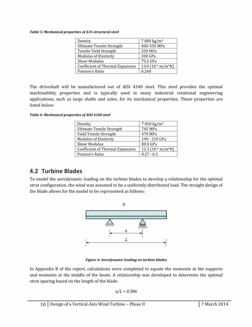
4.2 Turbine Blades To model the aerodynamic loading on the turbine blades to develop a relationship for the optimal
strut configuration, the wind was assumed to be a uniformly distributed load. The straight design of
the blade allows for the model to be represented as follows:
Figure 6: Aerodynamic loading on turbine blades
In Appendix B of the report, calculations were completed to equate the moments at the supports
and moments at the middle of the beam. A relationship was developed to determine the optimal
strut spacing based on the length of the blade.
a/L = 0.586
11 Design of a Vertical-Axis Wind Turbine – Phase II 7 March 2014
Where a is the spacing between the struts and L is the length or height of the blade. Therefore, the
optimal strut spacing is 58.5% of the turbine blade length.
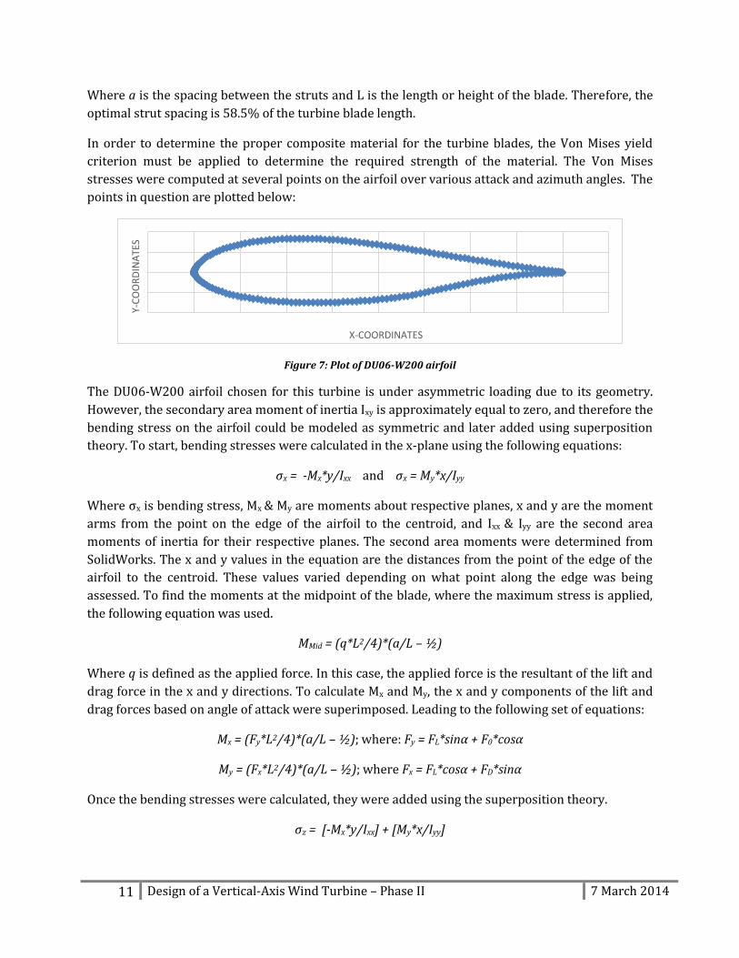
In order to determine the proper composite material for the turbine blades, the Von Mises yield
criterion must be applied to determine the required strength of the material. The Von Mises
stresses were computed at several points on the airfoil over various attack and azimuth angles. The
points in question are plotted below:
Figure 7: Plot of DU06-W200 airfoil
The DU06-W200 airfoil chosen for this turbine is under asymmetric loading due to its geometry.
However, the secondary area moment of inertia Ixy is approximately equal to zero, and therefore the
bending stress on the airfoil could be modeled as symmetric and later added using superposition
theory. To start, bending stresses were calculated in the x-plane using the following equations:
σx = -Mx*y/Ixx and σx = My*x/Iyy
Where σx is bending stress, Mx & My are moments about respective planes, x and y are the moment
arms from the point on the edge of the airfoil to the centroid, and Ixx & Iyy are the second area
moments of inertia for their respective planes. The second area moments were determined from
SolidWorks. The x and y values in the equation are the distances from the point of the edge of the
airfoil to the centroid. These values varied depending on what point along the edge was being
assessed. To find the moments at the midpoint of the blade, where the maximum stress is applied,
the following equation was used.
MMid = (q*L2/4)*(a/L – ½)
Where q is defined as the applied force. In this case, the applied force is the resultant of the lift and
drag force in the x and y directions. To calculate Mx and My, the x and y components of the lift and
drag forces based on angle of attack were superimposed. Leading to the following set of equations:
Mx = (Fy*L2/4)*(a/L – ½); where: Fy = FL*sinα + F0*cosα
My = (Fx*L2/4)*(a/L – ½); where Fx = FL*cosα + FD*sinα
Once the bending stresses were calculated, they were added using the superposition theory.
σz = [-Mx*y/Ixx] + [My*x/Iyy]
Y-C
OO
RD
INA
TES
X-COORDINATES
12 Design of a Vertical-Axis Wind Turbine – Phase II 7 March 2014
The next step in finding Von Mises stresses was to determine the torsional shear stress that
corresponds to its respective bending stress. The following equation was used:
τ = T*r/IP
Where T is torque caused by the lift and drag forces, r is the moment arm (typically the radius if the
torque is applied to a cylindrical shaft), and Ip is the polar moment of inertia. To generalize the
airfoil, the perimeter was found and translated into the circumference of a circle. This method will
give a rough approximation of the shear stress by means of shape factoring, using the circle to find a
proportional radius for the calculation. IP was determined through the use of SolidWorks and the
torque was determine by finding the moment caused by lift and drag about the centroid. The lift
and drag forces are applied at the centre of lift, which is 0.25*chord from the leading edge. Due to
the orientation of the airfoil the x components of the lift and drag are applied through the same
plane as the centroid and therefore do not cause moments. However, the y components cause a
moment that is modeled as follows:
Ty = [FL*sinα + FD*cosα]*β
Where Ty is the torque caused by the y components of the lift and drag forces and β is the horizontal
distance between the centroid and the centre of lift. This torque with the radius of the translated
circle and IP can be used to calculate an approximate shear stress.
The equation for Von Mises yield criterion includes the bending and shear stresses calculated
above. The stress calculated using Von Mises will be used to select a composite material in the next
phase of the project. The Von Mises stress formula is as follows:
√[
]
Using Microsoft Excel, σmax was determine to be 5.3 MPa at an azimuth angle of 27.5 degrees.
4.3 Driveshaft The design of the turbine driveshaft was primarily governed by the torque generated from the
rotating blades.
The yield strength of AISI 4340 is:
Since the maximum principal stress is σy and the minimum principal stress is zero, from the
Maximum Shear Stress Theory:
The torsion formula for a solid cylindrical shaft is:
13 Design of a Vertical-Axis Wind Turbine – Phase II 7 March 2014
Where,
[
]
T – torque (N*m)
Do – outer diameter (m)
Di – inner diameter (m)
4.3.1 Driveshaft – Results Using the torsion formula, a multitude of values could be selected for the inner and outer diameters
of the shaft provided the calculated torsion does not exceed the allowable shear stress. For the
initial sizing, inner and outer diameters of 0.26 m and 0.3 m were selected. From the initial
aerodynamic analysis using QBlade, the maximum torque on the drive shaft was approximately 100
000 N*m. Thus, using the torsion formula:
Since the torsion is less than the allowable shear stress, the selected shaft dimensions are
appropriate with a safety factor of 4.9.
4.4 Driveshaft Components There are many types of bearings and couplings to consider when designing a vertical rotational
shaft. The VAWT, as noted in the previous section, will contain a driveshaft that consists of two
equal length shafts. To support and connect these shafts, the bearings and couplings must be able to
satisfy the torsional and axial loads. Other design criteria for bearing and coupling selection are life
span, reliability, cost and material.
4.4.1 Bearings When choosing a bearing, it is important to know what types of bearings are available on the
market and how functions are required of the bearing. Types of bearings include ball bearings,
roller bearings, and thrust bearings. Typically, bearings are manufactured to withstand radial loads,
thrust loads, or a combination of both. For the driveshaft of the vertical axis wind turbine, a
combination of radial and thrust loading will be required. This led to a comparison of tapered roller
bearings and angular contact ball bearings. Angular contact ball bearings are generally used for
high rotational speed and relatively lower loads, in contrast to tapered roller bearings which are
used for lower rotational speed and higher loads. With the requirements of a heavy force load at a
low rotational speed of approximately 30 rpm, it was decided that the optimal bearing would be a
tapered roller bearing.
14 Design of a Vertical-Axis Wind Turbine – Phase II 7 March 2014
4.4.2 Mechanical Couplings The VAWT drive shaft is required to be sectioned in order to meet the shipping criteria set in the
project objectives. A mechanical connection is required to join the sectional drive shaft upon
installation and compensate for misalignment and thermal expansion in service. To select a
coupling, the features required of the coupling must first be determined. Mechanical shaft couplings
can be either rigid, flexible/compensating, or clutch type couplings. For the VAWT driveshaft
assembly, the coupling must connect two shafts together, transmit a relatively high torque at low
rotational speeds, require minimal maintenance, and provide sufficient flexure and axial relief. Due
to the constraints, clutch type and rigid couplings can be eliminated immediately from the design,
making the coupling of choice flexible or compensating. With the constraints determined to be
minimal maintenance, low cost, and high life expectancy, companies that supply various types of
couplings were investigated. These companies include:
Love-Joy
Ruland
Hayes
Renold
Renold has been contacted regarding information on the “Renold Hi-Tec RB” mechanical coupling
that specifies shaft to shaft connection for applications such as wind turbines. The features listed
for the coupling include the following:
Intrinsically fail safe
Control of resonant torsional vibration
Maintenance free
Severe shock load protection
Misalignment capability
Zero backlash
Low cost
The driving features of this coupling are the misalignment capability and maintenance free
attributes. These features provide significant advantages over common connections such as
constant-velocity joints or universal joints, because they do not require any lubrication and can
allow for axial as well as angular misalignment.
4.5 Tower The tower was analyzed as a vertical hollow cylinder subjected to wind loads, rotor forces, and the
weight of the VAWT itself. This will cause axial stresses, shear stresses and bending stresses in the
structure. The tower supports the upper structure and protects the shaft from the elements (wind,
rain, snow, etc.). To reduce the amount of material, it was important to minimize the thickness and
withstand the worst possible wind loads.
15 Design of a Vertical-Axis Wind Turbine – Phase II 7 March 2014
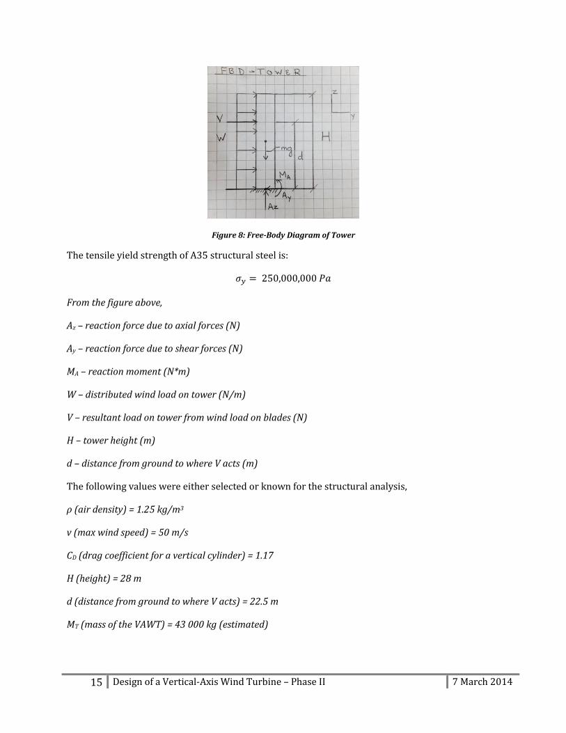
Figure 8: Free-Body Diagram of Tower
The tensile yield strength of A35 structural steel is:
From the figure above,
Az – reaction force due to axial forces (N)
Ay – reaction force due to shear forces (N)
MA – reaction moment (N*m)
W – distributed wind load on tower (N/m)
V – resultant load on tower from wind load on blades (N)
H – tower height (m)
d – distance from ground to where V acts (m)
The following values were either selected or known for the structural analysis,
ρ (air density) = 1.25 kg/m3
v (max wind speed) = 50 m/s
CD (drag coefficient for a vertical cylinder) = 1.17
H (height) = 28 m
d (distance from ground to where V acts) = 22.5 m
MT (mass of the VAWT) = 43 000 kg (estimated)
16 Design of a Vertical-Axis Wind Turbine – Phase II 7 March 2014
4.5.1 Tower – Axial Stress From basic solid mechanics, the axial stress at the base of the structure is:
Where,
P – axial reaction force (total weight of the VAWT) (N)
A – cross-sectional area of the tower (m2)
4.5.2 Tower – Shear Stress The shear stress in the tower structure is caused by wind loads on the tower and the resultant wind
loads on the blades (obtained during aerodynamic analysis). The formula for the resultant force
caused by wind loading on the tower is:
Where,
ρ – density of air (kg/m3)
v – wind velocity (m/s)
CD – drag coefficient
Do*H – projected area where the wind load is applied (for a vertical cylinder, the projected area is the
outer diameter multiplied by the height) (m2)
The following equation was used to convert the single load (FW) to a distributed load on the tower:
Since the wind loading on the blades is constantly varying, the maximum wind force had to be
obtained through aerodynamic analysis. Using Excel, the resultant blade wind loads were computed
at a variety of azimuth angles (θ). The highest resultant force (FR) was approximately 60,000 N at
an azimuth angle of 32.5 degrees.
From basic solid mechanics, the shear stress at the base of the structure is:
Where,
17 Design of a Vertical-Axis Wind Turbine – Phase II 7 March 2014
A – cross-sectional area of the tower (m2)
4.5.3 Tower – Bending As with the shear stresses, the bending stresses are caused by wind loads on the tower and the
resultant wind loads on the blades.
The tower was modeled as a vertical beam with a fixed support at one end. Therefore, from solid
mechanics the maximum bending moment at the base of the structure is:
Where,
W – distributed wind load on the tower (N/m)
H – height of the tower (m)
FR – resultant blade loading (N)
d – distance from the ground to where FR acts (m)
The maximum bending moment was then used to calculate the bending stress using the following
equation:
Where,
(
) ⁄
Mmax – maximum bending moment (N*m)
Do/2 – distance from the neutral axis to the point where stress is being calculated (m)
4.5.4 Tower – Von Mises Stresses The Von Mises yield criterion was applied to the bending, axial, and shear stresses to determine the
Von Mises principal stresses. The maximum Von Mises stress will be used to determine if the
selected material and dimensions are valid. If the maximum Von Mises stress is lower than the yield
strength of the material, and give an appropriate safety factor, the dimensions and material are
valid. Conversely, if the maximum Von Mises stress exceeds the yield strength of the material, then
larger dimensions and/or an alternate material are required. The Von Mises stresses were
computed in Excel using the following formula:
18 Design of a Vertical-Axis Wind Turbine – Phase II 7 March 2014
|( )
| √[
( )
]
[ ]
4.5.5 Tower – Results The maximum Von Mises stress was determined to be 25 MPa, assuming an inner diameter of 2
meters, a thickness of 0.0254 meters (1 inch), and A35 structural steel as the material. The inner
diameter should be at least 2 meters to allow for access to the interior components (drive shaft,
bearings, etc.) for maintenance purposes. Since the yield strength of A35 steel is 250 MPa, the safety
factor of the structure is 10. Therefore, the dimensions and material are appropriate for this stage
of the design.
5 ENVIRONMENT Based on the feedback from phase one of the project MUN VAWT Design decided to investigate the
impact of wind turbines on the avian population to assuage the fears raised by many people. A 2001
investigation into the causes of avian collision mortality in the United States estimated that wind
turbines accounted for only 0.01 to 0.02% of the total fatalities. [8] More recently, a 2013 Canadian
study estimated that the average number of avian deaths per turbine was 8.2 ± 1.4. However, it
found this was heavily dependent on location has the average ranged from 0 to 26.9 deaths per
turbine. [9] With this in mind, Nain, the location previously discussed as an area of interest was
investigated for potential avian impacts on a proposed wind turbine project. By reading
Environmental Assessment’s for two different wind turbine project’s proposed for Nain in the past
it was found that Nain is designated an Important Bird Area (IBA). However this title carries no
legal repercussions and Nain is therefore not a legally protected Ecological Reserve. An IBA is an
area that meets the requirement set out by the IBA program for monitoring and designation of
important areas for the conservation of birds. [10] It was also found that there are 8 Peregrine
Falcon, which are considered a threatened species, nests in the surrounding area of Nain. Due to
this a 1 km radius around the nest sites was proposed as a buffer zone. [11] The last consideration
found was a condition on the release of the project from Governmental review mandating that an
avian monitoring program be developed in line with Environment Canada regulations. [12]
6 PRELIMINARY ECONOMIC ANALYSIS The cost estimates in this report are extrapolations from the economic analysis of Northwind 100,
the 100kW wind turbine used by Nalcor in Ramea, Newfoundland, and the diesel generators in
Nain, Labrador. [13] [14] Using engineering economic principles, the monetary values for
maintenance costs, fuel consumption and capital costs were translated through time with an
interest rate of 3.5% using the equation below:
F = P (1 + i)n
19 Design of a Vertical-Axis Wind Turbine – Phase II 7 March 2014
Where F is the monetary or accumulated value at a future point in time, P is the current or principal
value, i is the interest rate and n is the number of years or interest periods between the present and
future.
The following findings are estimates only, since the actual cost of the VAWT has not been finalized,
and because transportation costs for both diesel fuel and the VAWT have not yet been considered.
In the final stage of this project there will be an accurate cost analysis for the VAWT based on
quotes and cost estimates from venders and manufactures.
Table 7: Key economic estimates
Estimated Capital Cost $500 000.00 Maintenance Cost/Year - Turbine $10 000.00 Maintenance Cost/Year – Diesel Generator $20 000.00 Fuel Cost for 2015 $3 630 967.00 Payoff Period for a Single Turbine 2 years
Payoff Period for an Installation of 5 Turbines 3 years
Payoff Period for an Installation of 20 Turbines 4 years
Payoff Period for an Installation of 50 Turbines 4 years
An initial installation of five turbines will produce sufficient power to reduce annual fuel costs by
approximately $750 000. This corresponds to a saving of 15% of the total cost of power generation
in the target location.
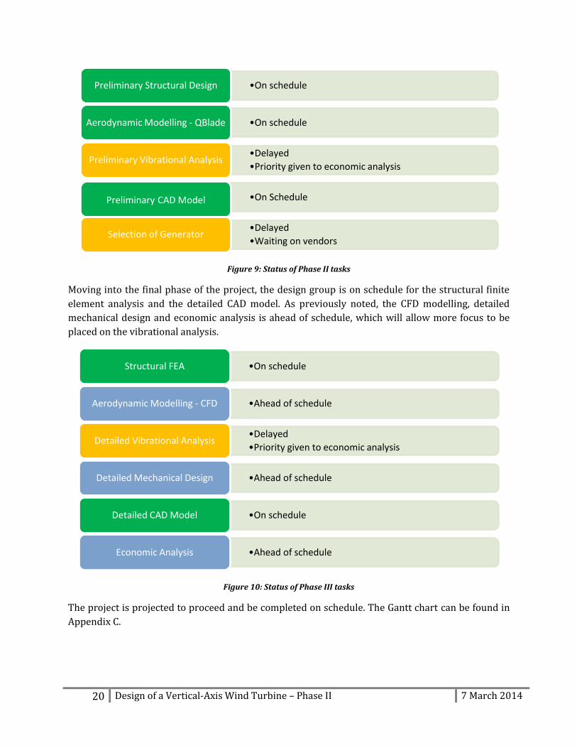
7 PROGRESS REPORT With the closure of Phase II, it is important to highlight the areas where progress met, exceeded, or
fell short of expectations. The majority of the goals were met including the preliminary structural
design, aerodynamic modelling in Q-Blade and production of the preliminary CAD Model. The
design group over-achieved in aerodynamic CFD modelling detailed mechanical design, and the
economic analysis. However, the preliminary vibrational analysis and generator selection were
pushed to Phase III in favour of a preliminary economic analysis. The selection of the induction
generator was delayed due to lack of communication on the vender’s behalf. The design group has
contacted venders and are awaiting a reply.
20 Design of a Vertical-Axis Wind Turbine – Phase II 7 March 2014
Figure 9: Status of Phase II tasks
Moving into the final phase of the project, the design group is on schedule for the structural finite
element analysis and the detailed CAD model. As previously noted, the CFD modelling, detailed
mechanical design and economic analysis is ahead of schedule, which will allow more focus to be
placed on the vibrational analysis.
Figure 10: Status of Phase III tasks
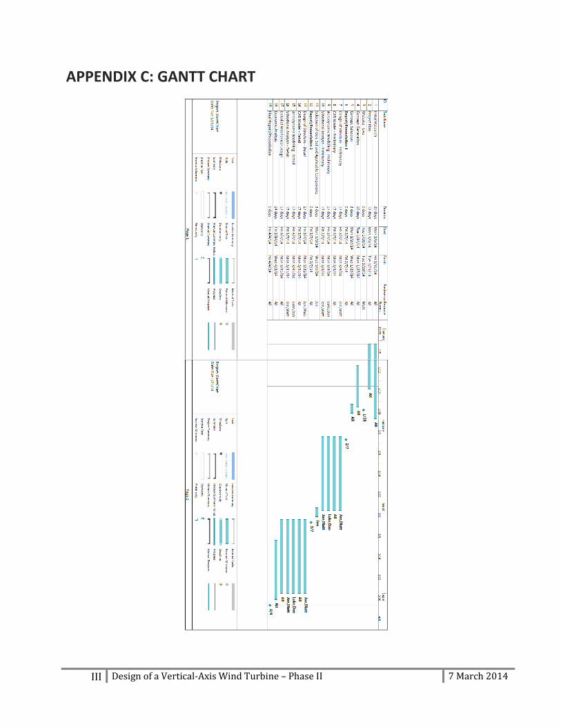
The project is projected to proceed and be completed on schedule. The Gantt chart can be found in
Appendix C.
•On schedule Preliminary Structural Design
•On schedule Aerodynamic Modelling - QBlade
•Delayed
•Priority given to economic analysis Preliminary Vibrational Analysis
•On Schedule Preliminary CAD Model
•Delayed
•Waiting on vendors Selection of Generator
•On schedule Structural FEA
•Ahead of schedule Aerodynamic Modelling - CFD
•Delayed
•Priority given to economic analysis Detailed Vibrational Analysis
•Ahead of schedule Detailed Mechanical Design
•On schedule Detailed CAD Model
•Ahead of schedule Economic Analysis
21 Design of a Vertical-Axis Wind Turbine – Phase II 7 March 2014
8 CONCLUSION During Phase II of the project, aerodynamic and structural analysis was carried out on the desired
turbine design. These analyses concluded that the turbine will be able to produce the target power
output, and that the structural and mechanical design of a VAWT of this size that complies to the
relevant standard is feasible using conventional materials. Based on the parameters computed from
aerodynamic modelling, a preliminary economic analysis was conducted, which shows that a
turbine of this design will be economically viable.
I Design of a Vertical-Axis Wind Turbine – Phase II 7 March 2014
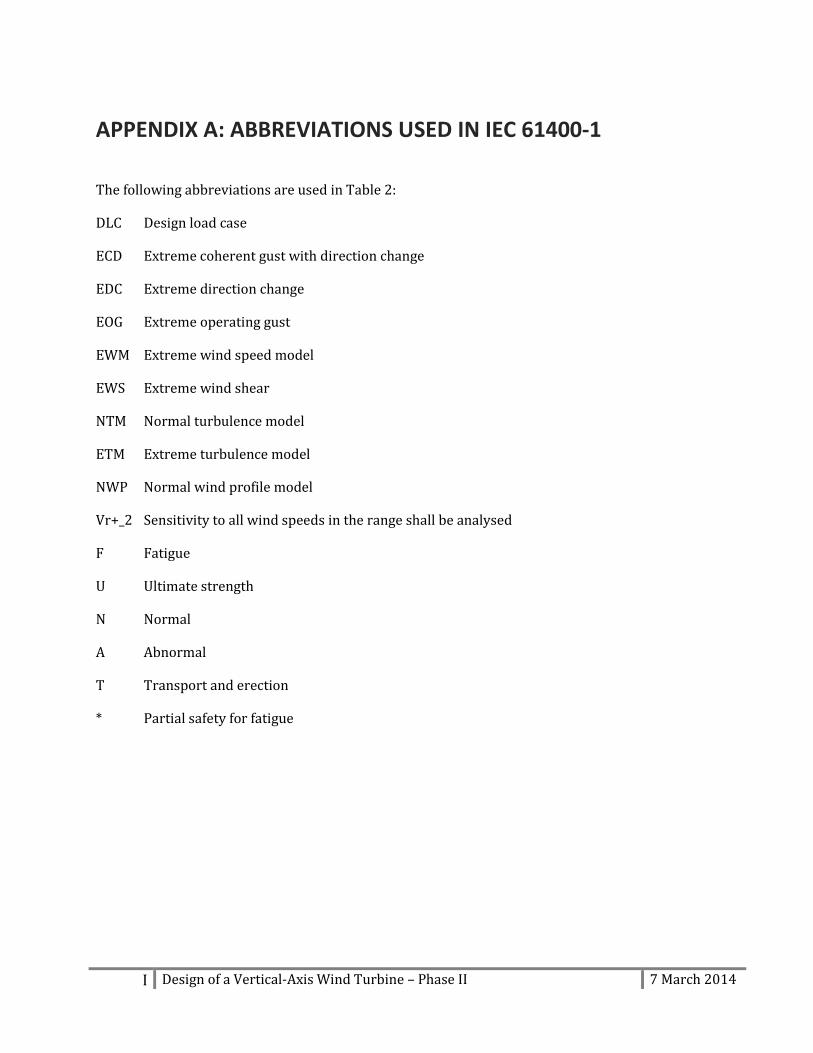
APPENDIX A: ABBREVIATIONS USED IN IEC 61400-1
The following abbreviations are used in Table 2:
DLC Design load case
ECD Extreme coherent gust with direction change
EDC Extreme direction change
EOG Extreme operating gust
EWM Extreme wind speed model
EWS Extreme wind shear
NTM Normal turbulence model
ETM Extreme turbulence model
NWP Normal wind profile model
Vr+_2 Sensitivity to all wind speeds in the range shall be analysed
F Fatigue
U Ultimate strength
N Normal
A Abnormal
T Transport and erection
* Partial safety for fatigue
II Design of a Vertical-Axis Wind Turbine – Phase II 7 March 2014
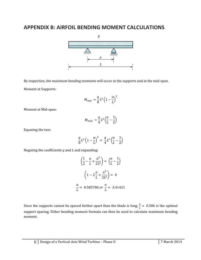
APPENDIX B: AIRFOIL BENDING MOMENT CALCULATIONS
By inspection, the maximum bending moments will occur at the supports and at the mid-span.
Moment at Supports:
(
)
Moment at Mid-span:
(
)
Equating the two:
(
)
(
)
Negating the coefficients q and L and expanding:
(
) (
)
(
)
Since the supports cannot be spaced farther apart than the blade is long,
is the optimal
support spacing. Either bending moment formula can then be used to calculate maximum bending
moment.
III Design of a Vertical-Axis Wind Turbine – Phase II 7 March 2014
APPENDIX C: GANTT CHART
IV Design of a Vertical-Axis Wind Turbine – Phase II 7 March 2014
BIBLIOGRAPHY
[1] International Electrotechnical Commision, IEC 61400-1, Edition 3.0, 2005-08, 2005.
[2] D. Marten and J. Wendler, "QBlade Guidelines v0.6," Technische Universität Berlin, Berlin, 2013.
[3] J. F. Manwell, J. G. McGowan and A. L. Rogers, Wind Energy Explained: Theory, Design and Application, John Wiley & Sons, 2010.
[4] S. Eriksson, H. Bernhoff and M. Leijon, "Evaluation of different turbine concepts for wind power," Swedish Centre for Renewable Electric Energy Conversion, Uppsala, 2006.
[5] A. Shires, "Development and Evaluation of an Aerodynamic Model for a Novel Vertical Axis Wind Turbine Concept," Cranfield University School of Engineering, Cranfield, 2013.
[6] G. Quandt, "Wind Turbine Trailing Edge Aerodynamic Brake Design," National Renewable Energy Laboratory, 1996.
[7] K. Rajambal, B. Umamaheswari and C. Chellamuthu, "Electrical braking of large wind turbines," Renewable Energy, vol. 30, no. 15, pp. 2235-2245, 2005.
[8] W. P. Erickson, G. D. Johnson, M. D. Strickland, D. P. Young, K. J. Sernka and R. E. Good, "Avian Collisions wiith Wind Turbines: A Summary of Existing Studies and Comparisons to Other Sources of Avian Collision Mortality in the United States," National Wind Coordinating Committee, 2001.
[9] J. R. Zimmerling, A. C. Pomeroy, M. V. d'Entremont and C. M. Francis, "Canadian Estimate of Bird Mortality Due to Collisions and Direct Habitat Loss Associated with Wind Turbine Developments," vol. 8, no. 2, 2013.
[10] Westenwind nv, "Environmental Registration; Nain," 2003.
[11] Unity Bay Energy Limited, "Environmental Assessment Registration; 750 kW Wind Turbine Farm; Nain, Labrador," 2003.
[12] Newfoundland & Labrador Department of Environment, "Environmental Assessment Bulletin," 2003.
[13] Newfoundland & Labrador Hydro, "Additions to Accommodate Load Growth - Isolated Generating Stations," 2012.
[14] Newfoundland & Labrador Hydro, "Preliminary Assesment of Alternative Energy Potential in Coastal Labrador," 2009.