Embed Size (px)
Citation preview

Design of a surface-mounted PM motor for improved flux weakening performance
Article:
Pastellides, S.G., Gerber, S., Wang, R-J., Kamper, M.J. (2020) Design of a surface-mounted PM motor for improved flux weakening performance, Proc. of XXIV International Conference on Electrical Machines, (ICEM), pp. 1772-1778, 23-26 August 2020, Gothenburg, Sweden (virtual conference)
ISBN: 978-1-7281-9944-3 / IEEE Catalogue Number: CFP2090B-USB
Reuse Unless indicated otherwise, full text items are protected by copyright with all rights reserved. Archived content may only be used for academic research.

Design of a Surface-Mounted PM Motor forImproved Flux Weakening Performance
Stavros Pastellides, Stiaan Gerber, Rong-Jie Wang and Maarten J. Kamper
Abstract—In this paper a surface-mounted permanent mag-net motor with a distributed overlapping winding is designedfor a light electric vehicle. The motor specifications are derivedfrom the vehicle physics model where the operating points aredetermined. A theoretical understanding is developed of howto improve the motor’s speed range through changes in theequivalent circuit parameters and the resulting effect on thegeometry. It is shown that with an increase in inverter size, amore cost effective motor design is achievable. An optimisationis conducted for the specified motor to find the most costeffective design based on a selected inverter size. The optimiseddesign is shown to withstand a short-circuit condition withoutmagnet degradation. Further the optimisation shows that, fora conventional surface-mounted permanent magnet motor, awide flux weakening range can be realised by increasing theslot-leakage inductance.
Index Terms—Design optimisation, electric vehicles, fluxweakening, permanent magnet motors, surface-mounted, trac-tion motors
I. INTRODUCTION
Globally, light electric vehicles (LEV) are increasinglyused in both urban environments, factories and warehousefacilities. Comparing with internal combustion engines (ICE),electric motors are more energy efficient and their torque-speed characteristics are better suited for the requirements ofthe specified applications. Although different electric motortechnologies are available for electric vehicle (EV) applica-tions, permanent magnet (PM) machines are often consideredin the implementation of EVs [1]–[5]. Among them, thesurface-mounted PM (SPM) and interior PM (IPM) machinesare the most common topologies.
Whilst the SPM motor has a better PM utilization factorthan its IPM counterpart [6], [7], the relatively narrow con-stant power speed range (CPSR) and demagnetization risksoften pose design challenges. To improve the flux weakeningperformance of SPMs, fractional-slot non-overlap winding(FSNOW) configurations have been proposed in literature[8]–[11].
Generally, the FSNOW has the potential benefits ofpossessing an increased magnetising inductance and theimproved flux weakening performance. Furthermore the end-winding length is significantly shorter when compared with
This work was supported by ABB Corporate Research, Sweden andStellenbosch University in South Africa
The authors are with the Department of Electrical and Electronic En-gineering, Stellenbosch University, Stellenbosch 7600, South Africa (e-mail: [email protected]; [email protected]; [email protected]; [email protected])
Fig. 1. The battery powered campus security vehicle.
overlap windings, thus, resulting in lower losses and easiermanufacturability. However, the magnetic fields of FSNOWmachines have rich space harmonics. These sub- and highharmonics have negative impact on the machine performancecausing localized core saturation, excessive iron and PMlosses [12], which are the main disadvantages of FSNOWs.
In this paper a SPM motor with conventional distributedoverlap winding is designed for a battery powered campussecurity vehicle. To improve on the flux weakening perfor-mance, the SPM motor parameters relating to the CPSR wereanalysed, which shows that the conventional SPM motor canbe designed with a wide CPSR by increasing stator leakageinductances.
II. TRACTION MOTOR AND LEV
This study focuses on the design of a traction motor fora campus security vehicle (shown in Fig. 1). An analysisusing the basic vehicle physics model, which incorporatesthe vehicles resistances and acceleration, is first conductedfor the LEV [13], [14]. The design specifications of thedrive-train components are determined based on the requiredvehicle performance, summarised in Table I. For this motor,the required output power is 3 kW, and the maximum speed ofthe vehicle is 50 km/h. The drive train of the vehicle operatesthrough a back axle drive, with the motor being coupled toa magnetic gear (MG) as shown in Fig. 2.
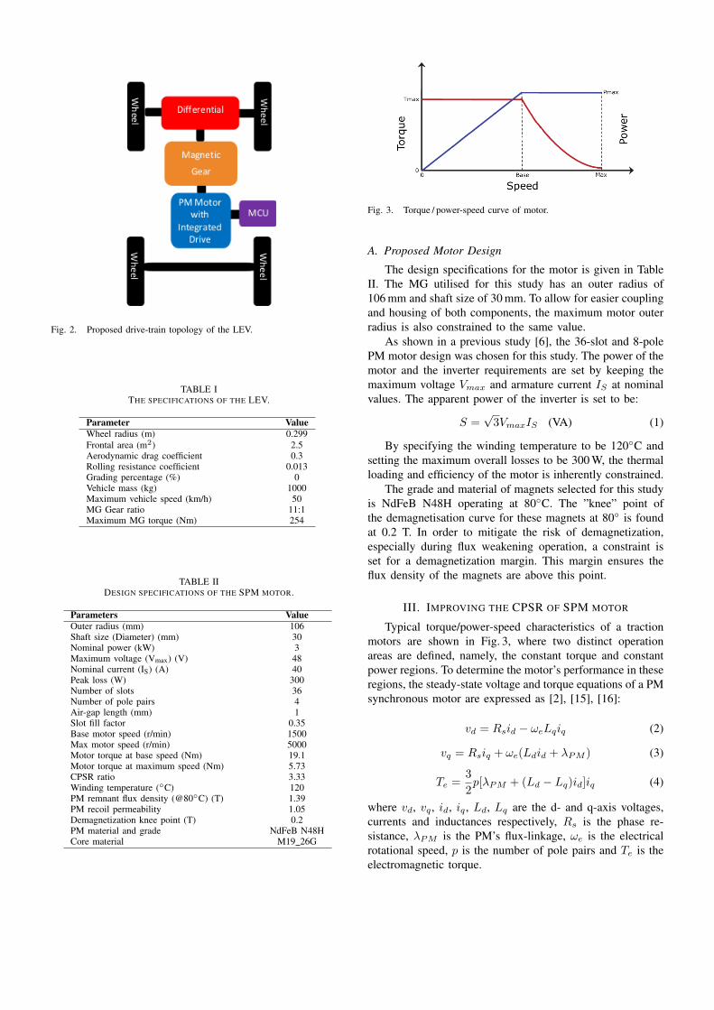
Fig. 2. Proposed drive-train topology of the LEV.
TABLE ITHE SPECIFICATIONS OF THE LEV.
Parameter ValueWheel radius (m) 0.299Frontal area (m2) 2.5Aerodynamic drag coefficient 0.3Rolling resistance coefficient 0.013Grading percentage (%) 0Vehicle mass (kg) 1000Maximum vehicle speed (km/h) 50MG Gear ratio 11:1Maximum MG torque (Nm) 254
TABLE IIDESIGN SPECIFICATIONS OF THE SPM MOTOR.
Parameters ValueOuter radius (mm) 106Shaft size (Diameter) (mm) 30Nominal power (kW) 3Maximum voltage (Vmax) (V) 48Nominal current (IS) (A) 40Peak loss (W) 300Number of slots 36Number of pole pairs 4Air-gap length (mm) 1Slot fill factor 0.35Base motor speed (r/min) 1500Max motor speed (r/min) 5000Motor torque at base speed (Nm) 19.1Motor torque at maximum speed (Nm) 5.73CPSR ratio 3.33Winding temperature (C) 120PM remnant flux density (@80C) (T) 1.39PM recoil permeability 1.05Demagnetization knee point (T) 0.2PM material and grade NdFeB N48HCore material M19 26G
Fig. 3. Torque / power-speed curve of motor.
A. Proposed Motor Design
The design specifications for the motor is given in TableII. The MG utilised for this study has an outer radius of106 mm and shaft size of 30 mm. To allow for easier couplingand housing of both components, the maximum motor outerradius is also constrained to the same value.
As shown in a previous study [6], the 36-slot and 8-polePM motor design was chosen for this study. The power of themotor and the inverter requirements are set by keeping themaximum voltage Vmax and armature current IS at nominalvalues. The apparent power of the inverter is set to be:
S =√3VmaxIS (VA) (1)
By specifying the winding temperature to be 120C andsetting the maximum overall losses to be 300 W, the thermalloading and efficiency of the motor is inherently constrained.
The grade and material of magnets selected for this studyis NdFeB N48H operating at 80C. The ”knee” point ofthe demagnetisation curve for these magnets at 80 is foundat 0.2 T. In order to mitigate the risk of demagnetization,especially during flux weakening operation, a constraint isset for a demagnetization margin. This margin ensures theflux density of the magnets are above this point.
III. IMPROVING THE CPSR OF SPM MOTOR
Typical torque/power-speed characteristics of a tractionmotors are shown in Fig. 3, where two distinct operationareas are defined, namely, the constant torque and constantpower regions. To determine the motor’s performance in theseregions, the steady-state voltage and torque equations of a PMsynchronous motor are expressed as [2], [15], [16]:
vd = Rsid − ωeLqiq (2)
vq = Rsiq + ωe(Ldid + λPM ) (3)
Te =3
2p[λPM + (Ld − Lq)id]iq (4)
where vd, vq , id, iq , Ld, Lq are the d- and q-axis voltages,currents and inductances respectively, Rs is the phase re-sistance, λPM is the PM’s flux-linkage, ωe is the electricalrotational speed, p is the number of pole pairs and Te is theelectromagnetic torque.

Fig. 4. Current / voltage limit for a SPM in dq-current plane.
For any operating point of the motor, the current andvoltage limits, which is constrained by the inverter rating,should not be exceeded. These constraint limits can beexpressed as:
V 2max ≥ (v2d + v2q ) (5)
I2lim ≥ (i2d + i2q) (6)
From (6), a current limit circle with radius Is and a centreat the origin can be formulated within the dq-current plane.
A. CPSR Related Parameters of a SPM Motor
It can be assumed for a SPM motor that Ld = Lq = Ls[2], [8], [13], [16], where Ls is the synchronous inductance.Further, by assuming a negligible phase resistance, (2), (3)and (4) can be simplified as:
vd = −ωeLsiq (7)
vq = ωe(Lsid + λPM ) (8)
Te =3
2pλPM iq (9)
and by substituting (7) and (8) into (5), expression (5) canbe rewritten as:(
VmaxωeLs
)2
≥ i2q +
(id +
λPMLs
)2
(10)
which shows that the voltage is constrained by a circle with acentre point of (0, −λPM
Ls) and a radius of Vmax
ωeLs. The current
and voltage limit regions are shown in Fig. 4 in the dq-currentplane. At the base speed, shown as point A in Fig. 4, bothcircles intersect on the q-axis, where iq is at the current limitsubjecting also to the voltage constraint. From (10), the basespeed can be expressed as:
ωb =Vmax√
(LsIlim)2 + λ2PM(11)
Points A and B in Fig. 4, refer to the operating regionsfor the SPM. At Point A, the motor operates at the constanttorque region, whereas between points A to B is the flux
weakening operation range. For a finite speed motor drive,the maximum speed occurs where both constraint circles meetat a single point [17]. The maximum speed is thus:
ωmax =Vmax
λPM − LsIlim(12)
From (11) and (12), a CPSR factor (KCPSR) based on themaximum to base speed ratio can be defined as [18]:
KCPSR =ωmaxωb
=
√(LsIlim)2 + λ2PMλPM − LsIlim
(13)
Further, the characteristic current of a SPM is defined as [9]:
In =λPMLs
(14)
By decreasing In, which in turn shifts the voltage limitcircles in Fig. 4 to the right, an increase of CPSR can beachieved. As seen from (13) and (14), the PM flux linkagehas an effect on the CPSR, however, by altering λPM , thetorque capability of the motor is also affected. Alternatively,the synchronous inductance of the motor can be increased toreduce In and thus improve the CPSR of the motor [9]. Itcan be seen that the ideal flux weakening occurs when thethe characteristic current In equals the rated current Ilim,however, this will lead to the demagnetisation of the PMs.
B. Synchronous Inductance ComponentsThe synchronous inductance of a PM motor can be
expressed as [19]:
Ls = Lm + LL (15)
where Lm is the magnetising inductance and LL is theleakage inductance. The Lm can be further written as:
Lm = µ02mτpπ2pδef
l′(kws1Ns)2 (16)
where µ0 is the permeability of air, m is the number ofphases, τp is the pole pitch, δef is the effective air-gap, l′ isthe length of the machine and kws1Ns is the effective turnsof the winding with regards to the winding factor.
The leakage inductance has several components, whichcan be expressed as:
LL = Lσ + Le + Lh (17)
where Lσ is the slot leakage inductance, Le is the end-winding leakage inductances and Lh is the air-gap harmonicleakage inductance. The slot leakage inductance can bedefined by the equation below [19]:
Lσ =4m
Qµ0l′N2σu (18)
where Q is the number of slots and σu is the permeancefactor. For a double-layer winding, σu can be calculated as:
σu = k1S3
3S6+ k2
(S1
S5+
S7
S6 − S5lnS6
S5
)(19)
where k1 and k2 are the short pitching factors [19]. The statorparameters in (19) are shown in Fig. 5.

(a) Stator slot dimension variables.
(b) Rotor dimension variables.
Fig. 5. Motor geometry design variables for optimisation.
IV. OPTIMISATION FORMULATION
Optimising electrical machines for traction applicationscan be quite complicated since different performance charac-teristics are required at different operational speeds. The two-point optimisation strategy described in [6] is implementedin this study. These points were specified from the torquespeed specifications in Table II, i.e. base speed and maximumspeed. By analysing only these two points and ensuring theyare within the inverter requirements, the compliance of themotor performance over the full operating speed range isinherently ensured.
A. Optimisation algorithm
The optimisation method implemented for this study, wasthe sequential least squares programming algorithm (SLSQP)[20], which is a gradient-based optimisation method. TheSLSQP minimises a single objective function of multiplevariables, subjecting to some equality and inequality con-straints.
B. Optimisation problem
The optimisation simulations were conducted using anin-house 2D finite element (FE) package. By using the twooperating points, the optimisation problem is formulated as:
Minimise: F (X) = Ctotal
Subject to: T1 ≥ 19.1Nm T2 ≥ 5.73NmVmax1 ≤ 48V Vmax2 ≤ 48VIφ1 ≤ 40A Iφ2 ≤ 40APloss1 ≤ 300W Ploss2 ≤ 300WBMM1 ≥ 0.05T BMM2 ≥ 0.05T
where X represents the vector of design variables includingthe geometric variables as shown in Fig. 5, dq-currents for
TABLE IIICOSTS OF MATERIALS USED IN THE OPTIMISATION.
Material Cost (USD/kg)Permanent magnets (NdFeB) 50Electric steel lamination 2Copper 6.67
each operating point and the coil turns of the machine. Ctotalis the total cost of the machine. The costs of the constituentmaterials of a PM machine are given in Table III [21].T1 and T2 are the minimum required torques, Vmax1 andVmax2 are the maximum voltage limits, Iφ1 and Iφ2 are themaximum allowable phase currents, Ploss 1 and Ploss 2 are themaximum allowable total losses, and BMM1 and BMM2 arethe demagnetisation margins of magnets, for design point 1and 2, respectively.
Each design variable utilised in the optimisation has a sig-nificant influence on the motor performance for the specifiedoperating point. By tuning the dq-current design variables,the optimal current angle is inherently determined for thespecified point and hence the optimal torque. Further, byadjusting the geometric parameters, the magnetising and slotleakage inductances are changed, which has an impact on theflux weakening performance of the motor. However, with theadjustment of these parameters, the cost objective function isalso affected. The optimisation is required to determine theoptimal weight for each material while ensuring the operatingpoint specifications are met.
C. Inverter size versus motor costIt was found during the initial optimisation process, that
an adjustment of the inverter size has a significant influenceon the total cost of the motor design. The relationshipbetween the inverter size and the cost of the SPM motor isshown in Fig. 6, which was realised by performing multipledesign optimisations based on a range of inverter ratings.The increase in inverter size is realised by increasing themaximum current while maintaining the same maximumvoltage of 48 V. It is clear that the cost of the motor fallssharply with the increase of inverter rating.
It is generally difficult to find an exact unit cost per kVArating for inverters. This is due to the number of technolo-gies and topologies available which has costing differences.Nonetheless, it is estimated for this design, that as the inverterrating increases from 3.4 kVA to 4.1 kVA, the cost increasewill be minor relative to the savings of the motor.
From Fig. 6, the smallest inverter size possible for theset specifications is shown to be 3.4 kVA, with a total motorcost of 94 USD. From a system perspective, it is advisedthat an inverter with a rating of approximately 3.7 kVA isselected for this application. The motor cost is thus reducedto approximately 50 USD.
V. PERFORMANCE ANALYSIS
In this section, the optimisation results and performancecharacteristics of the designed SPM motor are discussed in

Fig. 6. Motor cost as a function of inverter size.
TABLE IVMOTOR DESIGN PARAMETERS.
Parameter Initial Optimum Design Final DesignSM PP1 0.728 0.756SM1 (mm) 42.27 31.03SM2 (mm) 1.29 1.8S1 (mm) 9.82 15.56S2 (mm) 3.34 2.89S3 (mm) 24.05 25.16S4 (mm) 10.798 13.72S5 (mm) 2 2S6 (mm) 9.09 9.44S7 (mm) 1.735 2.7Stack length (mm) 57.34 57.68Number of turns per coil 4 4
detail. An initial optimised design is first shown, followedby a refined optimised design that is able to withstand ashort-circuit condition without permanent demagnetisation.For validation purpose, the designs are determined by usingthe in-house FE package and have been analysed by theANSYS-Maxwell commercial package.
A. Operating point results
Figure 7 shows the initial optimised SPM motor designfor the inverter size of 3.7 kVA, with the geometric design
Fig. 7. Cross-section of initial optimised surface-mounted motor.
Fig. 8. Cross-section of optimised short-circuit tolerant surface-mountedmotor.
TABLE VOPERATING POINT RESULTS FOR OPTIMISED SHORT-CIRCUIT TOLERANT
DESIGN.
Parameter Optimised DesignOperating point → ωb = 1500 r/min ωmax = 5000 r/minTorque (Nm) 19.1 5.73Vmax (V) 48 48Irms (A) 44 44Copper losses (W) 234 234Core losses (W) 28.75 47Magnet losses (W) 8.75 16Demagnetisation margin (T) 0.136 0.225Constant power speed range 1 3.33Demagnetisation margin (T)(dynamic short-circuit state)
0.018 0.103
Short-circuit current (A) 74.08 64.52
parameters summarised in Table IV. The design was validatedat both base and maximum speed operating points, whichconfirms that the initial optimum design satisfies all thedesign specifications. To assess the short-circuit withstandcapability of the initial design, it is tested under a dynamicshort-circuit condition, as described in [22]. Unfortunately,the initial optimum design suffers severe demagnetisationrisk at either operating point. To mitigate this phenomenon,a further design optimisation was conducted, which resultedin a short-circuit tolerant optimised design shown in Fig. 8.The design parameters and the operating point results aresummarised for this design in Tables IV and V respectively.It can be observed that the design has thicker magnets toensure no demagnetisation occurs and a longer stator slotopening (parameter S1), which contributes to the slot leakageinductance and hence the total leakage flux of the motor.From Table V, the demagnetisation margin for the magnetsare shown to be well above the ”knee” point at eitheroperating point during standard operation. Further under ashort-circuit condition the magnets are within the ”knee”point of the demagnetisation curve, which will thereforeavoid any magnet degradation. The short-circuit characteristiccurrent is also seen to be 1.68 times the rated current at basespeed.

Fig. 9. Torque/power-speed characteristics of the final optimum design.
TABLE VIINDUCTANCE CHARACTERISTICS.
Parameter Initial Optimum Design Final DesignLs (µH) 834.51 850.14Lm (µH) 436.29 292.65Ll (µH) 398.22 557.49Lσ (µH) 361.09 515.39Le (µH) 35.71 35.36Lh (µH) 1.42 6.74Rφ (mΩ) 45.19 39.79
B. Analysis of inductance characteristics
From Section III, an increase in synchronous inductanceleads to an improvement in the CPSR of a SPM motor. InTable VI the inductance characteristics are given, with Lebeing the end winding inductance, Lh being the harmonicleakage inductance and Rφ being the terminal resistance. Forthe optimised short-circuit tolerant design, the magnetisinginductance Lm and the leakage inductance LL account for34.42% and 65.58% of the total synchronous inductance,respectively, which shows the leakage inductance has alarge contribution to the total synchronous inductance, whichimproves the flux weakening capability of the motor.
As given in Table VI, the slot leakage inductance Lσ isthe biggest contributor to the synchronous leakage inductancewhen compared to the end-winding and harmonic leakageinductances. It can be clearly seen from the geometric lay-outs of the optimum designs (Figs. 7-8) that an extendedparameter of S1 and S3 (see also Table IV) improves theslot leakage permeance factor (19), which in turn enhancesflux weakening capability.
C. Costing, mass and efficiency
The cost and mass of each material used in the initialand short-circuit tolerant optimal motor designs are given inTable VII. From the optimisation, the short-circuit tolerantdesign was determined with a minimal increase to the totalcost of the motor. As the PMs have the highest cost per kg,the optimisation determined a total PM mass of 0.173 kg forthe short-circuit tolerant design, with the total mass of the
TABLE VIIDESIGN CHARACTERISTICS.
Parameter Initial Optimum Design Final DesignCtotal (USD) 50.17 52.16Csteel (USD) 23.02 22.19Ccopper (USD) 19.8 21.28Cmagnet (USD) 7.34 8.69Mtotal (kg) 14.62 14.46Msteel (kg) 11.42 11.1Mcopper (kg) 2.97 3.19Mmagnet (kg) 0.146 0.173Vtotal (L) 2.02 2.04
Fig. 10. Efficiency map of the final optimum surface-mounted motor design.
motor being 14.46 kg. The total cost of the motor (based onthe active material) is about 52.16 USD.
Figure 10 shows the efficiency map of the short-circuittolerant optimised design. The efficiency map for the opti-mised design is generated assuming that the motor is alwaysoperated at maximum torque per ampere (MTPA). The totallosses considered in the map includes the sum of resistive,core and eddy current losses. The motors mechanical lossesare also considered, which was set to be 40 W at basespeed. From this, the base speed efficiency is 91 %, whilethe maximum speed efficiency is 83 %. The flux densitydistribution at base and maximum speed is depicted in Fig.11, which shows how the flux field is weakened when themotor operates at maximum speed, due to the significantsynchronous inductance.
Fig. 11. Flux density distribution in the final optimum SPM motor designat 1500 r/min and 5000 r/min respectively.

VI. CONCLUSION
In this paper, a surface-mounted permanent magnet ma-chine is designed using fractional-slot overlapping windingsfor a LEV. The motors parameters were designed to complywith certain specifications set for the LEV.
It was determined for a SPM design, in order to extendflux weakening capability, a large synchronous inductance isrequired. This can be accomplished by increasing the mag-netising and slot leakage inductance. A multi-point designoptimisation strategy was employed to search for the mostcost-effective design, while ensuring a wide CPSR.
Furthermore, in this study it was found that the invertersizing has a direct influence on the costing of the motor.As the size of the inverter was increased by 0.3 kVA, therewas a reduction in motor cost by 52%. This shows that byallowing the inverter constraint to relax up to a point, a morecost effective machine can be realised without compromisingsignificantly on the inverter’s rating.
It was determined that the initial optimised design will ex-perience magnet degradation under a short-circuit condition.Further design optimisation led to a final optimum design,which can withstand a dynamic short-circuit fault conditionwithout demagnetising the magnets.
Lastly it was found that a surface-mounted SPM designwith overlapping winding is able to achieve a wide CPSRwithout compromising on efficiency. This takes into accountthat no segmentation of magnets are employed, which mayfurther increase the motor’s efficiency.
REFERENCES
[1] J. Yan, K. Yang, S. Zhang, Y. Feng, Y. Chen, and H. Yang, “Com-parative investigation of inset-type and V-type IPMSM for lightelectric vehicle,” International Journal of Applied Electromagneticsand Mechanics, vol. 54, no. 4, pp. 515–524, 2017.
[2] A. G. Sarigiannidis, M. E. Beniakar, and A. G. Kladas, “Fast adaptiveevolutionary PM traction motor optimization based on electric vehicledrive cycle,” IEEE Transactions on Vehicular Technology, vol. 66,no. 7, pp. 5762–5774, 2016.
[3] G. Pellegrino, A. Vagati, P. Guglielmi, and B. Boazzo, “Performancecomparison between surface-mounted and interior PM motor drivesfor electric vehicle application,” IEEE Transactions on IndustrialElectronics, vol. 59, no. 2, pp. 803–811, 2011.
[4] K. M. Cisse, S. Hlioui, Y. Cheng, M. Belhadi, and M. Gabsi, “Opti-mization of V-shaped synchronous motor for automotive application,”in XIII International Conference on Electrical Machines (ICEM).IEEE, 2018, pp. 906–912.
[5] J. Wang, X. Yuan, and K. Atallah, “Design optimization of a surface-mounted permanent-magnet motor with concentrated windings forelectric vehicle applications,” IEEE Transactions on Vehicular Tech-nology, vol. 62, no. 3, pp. 1053–1064, 2012.
[6] S. Pastellides, S. Gerber, and R.-J. Wang, “Design strategy and compar-ison of four PM motor topologies for a 2 kW traction application,” inSouthern African Universities Power Engineering Conference/Roboticsand Mechatronics/Pattern Recognition Association of South Africa(SAUPEC/RobMech/PRASA). IEEE, 2019, pp. 358–363.
[7] R. Krishnan, Permanent magnet synchronous and brushless DC motordrives. CRC press, 2017.
[8] P. Ponomarev, P. Lindh, and J. Pyrhonen, “Effect of slot-and-polecombination on the leakage inductance and the performance of tooth-coil permanent-magnet synchronous machines,” IEEE Transactions onIndustrial Electronics, vol. 60, no. 10, pp. 4310–4317, 2012.
[9] A. M. El-Refaie and T. M. Jahns, “Optimal flux weakening in sur-face PM machines using fractional-slot concentrated windings,” IEEETransactions on Industry Applications, vol. 41, no. 3, pp. 790–800,2005.
[10] A. M. El-Refaie and T. M. Jahns, “Impact of winding layer number andmagnet type on synchronous surface PM machines designed for wideconstant-power speed range operation,” IEEE Transactions on EnergyConversion, vol. 23, no. 1, pp. 53–60, March 2008.
[11] Y. Duan, R. Harley, and T. Habetler, “Method for multi-objectiveoptimized designs of surface mount permanent magnet motors withconcentrated or distributed stator windings,” in IEEE InternationalElectric Machines and Drives Conference. IEEE, 2009, pp. 323–328.
[12] G. Dajaku and D. Gerling, “A novel tooth concentrated winding withlow space harmonic contents,” in International Electric Machines &Drives Conference. IEEE, 2013, pp. 755–760.
[13] K. T. Chau, Electric vehicle machines and drives. Wiley, 2015.[14] M. Ehsani, Y. Gao, S. Longo, and K. Ebrahimi, Modern electric, hybrid
electric, and fuel cell vehicles. CRC press, 2018.[15] H. Liu, Z. Zhu, E. Mohamed, Y. Fu, and X. Qi, “Flux-weakening
control of nonsalient pole PMSM having large winding inductance,accounting for resistive voltage drop and inverter nonlinearities,” IEEETransactions on Power Electronics, vol. 27, no. 2, pp. 942–952, 2011.
[16] J. F. Gieras, Permanent magnet motor technology: design and appli-cations. CRC press, 2009.
[17] S.-K. Sul, Control of electric machine drive systems. John Wiley &Sons, 2011.
[18] W. Gu, X. Zhu, L. Quan, and Y. Du, “Design and optimization of per-manent magnet brushless machines for electric vehicle applications,”Energies, vol. 8, no. 12, pp. 13 996–14 008, 2015.
[19] J. Pyrhonen, T. Jokinen, and V. Hrabovcova, Design of rotatingelectrical machines, 2nd ed. Wiley, 2014.
[20] D. Kraft and K. Schnepper, “SLSQP—a nonlinear programmingmethod with quadratic programming subproblems,” DLR, Oberpfaf-fenhofen, 1989.
[21] P. M. Tlali, R.-J. Wang, S. Gerber, C. D. Botha, and M. J. Kamper,“Design and performance comparison of vernier and conventionalPM synchronous wind generators,” IEEE Transactions on IndustryApplications, vol. 56, no. 3, pp. 2570–2579, 2020.
[22] J. Germishuizen and C. Adam, “Integrating FEM and existing tractionmotor design tools into an everyday engineering environment,” e & iElektrotechnik und Informationstechnik, vol. 136, no. 2, pp. 168–174,2019.
VII. BIOGRAPHIES
Stavros Pastellides received his B.Eng in Electrical Engineering at Stel-lenbosch University in 2017 where he is currently working as a Mastersresearcher. His main interests are electrical machine design, numericaloptimization, electric vehicle traction drive systems and renewable energysystems.
Stiaan Gerber received his Ph.D. in Electrical Engineering at StellenboschUniversity in 2015 where he is currently working as a postdoctoral re-searcher. His main interests in the engineering field are electrical machinedesign, magnetic gear technology, numerical optimization, finite elementmethods and renewable power generation. He is an avid software developerand has published more than 20 papers in recognized international journalsand conference proceedings.
Rong-Jie Wang received the M.Sc. degree in electrical engineering fromthe University of Cape Town in 1998 and the Ph.D. degree in electricalengineering from Stellenbosch University in 2003, all in South Africa. Heis currently an Associate Professor in the Department of Electrical andElectronic Engineering at Stellenbosch university. His research interestsinclude novel topologies of permanent magnet machines, computer-aideddesign and optimization of electrical machines, cooling design and analysis,and renewable energy systems.
Maarten Kamper received the M.Sc. (Eng.) and Ph.D. (Eng.) degrees fromthe Stellenbosch University in South Africa, in 1987 and 1996, respectively,in the field of design of induction and reluctance electrical machines.Since 1989, he has been with the Department of Electrical and ElectronicEngineering, Stellenbosch University, where he is currently a Professor ofelectrical machines and drives. His research interests include the designoptimization and control of electrical machines, currently with the focus onwind generators, synchronous condensers and industrial and electric vehicledrives. Prof Kamper is a senior member of the IEEE and a registeredprofessional engineer in South Africa.