Embed Size (px)
Citation preview
Design of a Differential Mode Active EMI Filter based on Conducted Emission Analysis Used in DC/DC Converter
Yuehong Yang1, Xinli Chang1, Wenjie Chen1, Xu Yang1
1State Key Lab. of Electrical Insul. and Power Equip., Xi’An Jiaotong Univ., 28 Xianning W. Rd., Xi’An, P. R. China
[email protected], [email protected], [email protected], [email protected]
Abstract This paper presents a novel active EMI filter (AEF) topology specially used to reduce the differential mode (DM) electromagnetic interference (EMI) noise in a full bridge DC/DC converter. The AEF was mainly reported to reduce the common mode (CM) EMI noise in the past, and the proposed circuit extends the application of the AEF to eliminate the DM EMI. In this work, differential mode emission conduct mechanism and full bridge DC/DC converter modeling are combined to develop a practical voltage feedback DM AEF, which is aimed to achieve a large insertion loss. Experimental results to demonstrate the performance and effectiveness of the proposed AEF are also presented.
1. Introduction With the extensively use of the switched mode power supplies (SMPS) nowadays, the fast changes in voltages and currents in the switching components will cause series conducted and radiated electromagnetic disturbances at high frequencies due to the existence of the parasitic inductors and capacitors in the circuit. The undesirable electromagnetic interference (EMI) will pollute the power system and influence the electric equipment nearby or itself too. In the existed literatures, the active EMI filter (AEF) is mainly used in the suppression of the common mode (CM) EMI noise [1-3]. While concerning of the eliminating of the differential mode (DM) EMI noise, it’s quite popular to use the passive EMI filter (PEF) in the past, because several large paralleled capacitors, accompanied with leakage inductance of the CM choke could acquire a decent tradeoff between the cost and simplicity. However, the size of the PEF is comparable with the converter itself[4]. With the development of the system integration, it’s quite practical to find a way to minimize the size of the DM EMI filter. In consideration of the good performance of AEF in suppression of CM noise, this paper proposes an idea of eliminating DM noise by using AEF. Properly speaking, active EMI filter is a kind of dynamical noise compensator and realized by feedback control[5]. It includes a current sense circuit for generating a signal proportional to the DM EMI noise, and then utilizes active components like amplifiers to reverse and amplify the noise signal, which will be subsequently injected into the main circuit by a controlled resistance. In this paper, with the analysis of the differential mode noise conduct mechanism and the noise source modeling of the converter, a novel active differential mode EMI filter topology is proposed to achieve a large insertion loss. The circuit is unique and prominent in that it is composed of a high speed op-amp and a low cost generally used op-amp cascaded with a power MOSFET. The experimental results on a 48V/300W full-bridge DC/DC converter prove the efficiency of the proposed AEF topology. This approach acquires a further reduction of the filter size and weight too.
2. Differential Mode Conducted Emission Analysis The noise source is a full-bridge DC/DC converter, shown in Fig.1. The parasitic capacitance in the MOSFET of a DC/DC converter is an essential factor for the conducted emission, because the parasitic capacitances will make resonant oscillations with the stray inductances to produce high frequency noise. DM and CM EMI noise are the two main conducted emission mechanisms in fulfillment of international EMC standards. The differential mode conducted emission in a full-bridge DC/DC converter is expounded in this paper.
Fig.1 Full-bridge DC/DC converter Fig.2 Equivalent circuit of the capacitor
This paper is supported by National Natural Science Foundation of China under Project 51277145.
978-1-4673-5225-3/14/$31.00 ©2014 IEEE
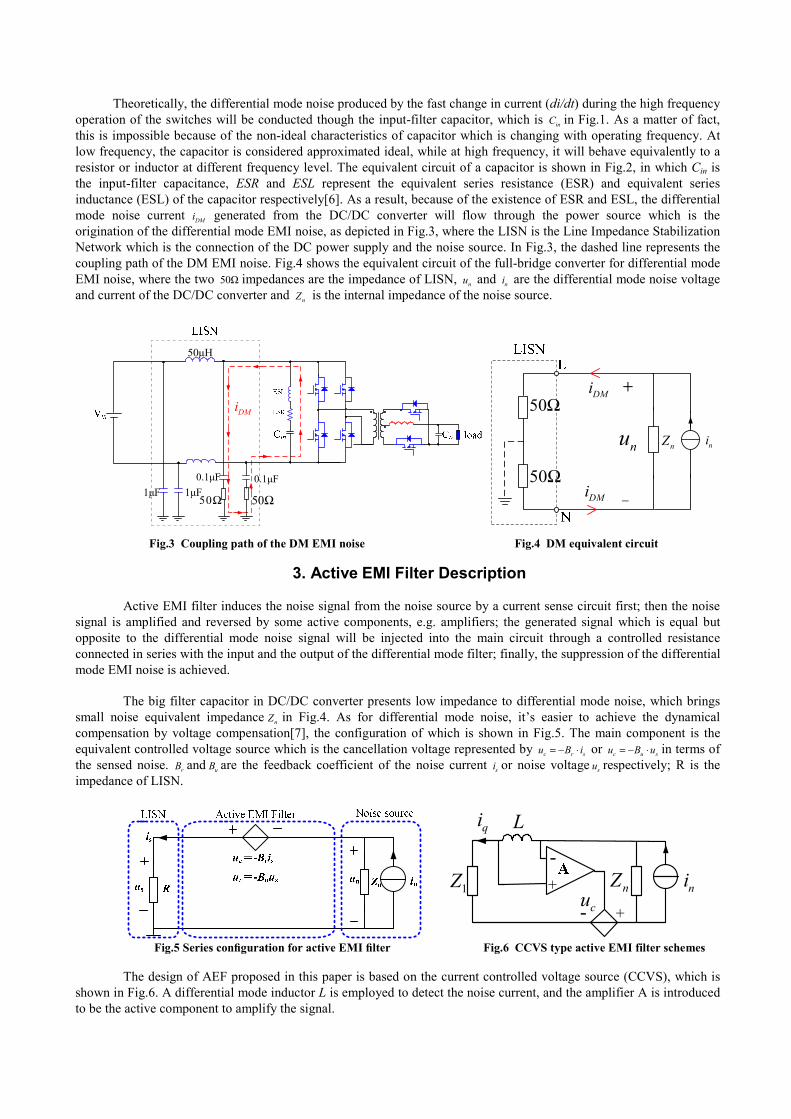
Theoretically, the differential mode noise produced by the fast change in current (di/dt) during the high frequency operation of the switches will be conducted though the input-filter capacitor, which is inC in Fig.1. As a matter of fact, this is impossible because of the non-ideal characteristics of capacitor which is changing with operating frequency. At low frequency, the capacitor is considered approximated ideal, while at high frequency, it will behave equivalently to a resistor or inductor at different frequency level. The equivalent circuit of a capacitor is shown in Fig.2, in which Cin is the input-filter capacitance, ESR and ESL represent the equivalent series resistance (ESR) and equivalent series inductance (ESL) of the capacitor respectively[6]. As a result, because of the existence of ESR and ESL, the differential mode noise current DMi generated from the DC/DC converter will flow through the power source which is the origination of the differential mode EMI noise, as depicted in Fig.3, where the LISN is the Line Impedance Stabilization Network which is the connection of the DC power supply and the noise source. In Fig.3, the dashed line represents the coupling path of the DM EMI noise. Fig.4 shows the equivalent circuit of the full-bridge converter for differential mode EMI noise, where the two 50Ω impedances are the impedance of LISN, nu and ni are the differential mode noise voltage and current of the DC/DC converter and nZ is the internal impedance of the noise source.
DMi
1μF 1μF0.1μF 0.1μF
50Ω 50Ω
50μH
50Ω
50Ω
DMi
nu nZ
DMi
ni
+
−
Fig.3 Coupling path of the DM EMI noise Fig.4 DM equivalent circuit
3. Active EMI Filter Description
Active EMI filter induces the noise signal from the noise source by a current sense circuit first; then the noise
signal is amplified and reversed by some active components, e.g. amplifiers; the generated signal which is equal but opposite to the differential mode noise signal will be injected into the main circuit through a controlled resistance connected in series with the input and the output of the differential mode filter; finally, the suppression of the differential mode EMI noise is achieved. The big filter capacitor in DC/DC converter presents low impedance to differential mode noise, which brings small noise equivalent impedance nZ in Fig.4. As for differential mode noise, it’s easier to achieve the dynamical compensation by voltage compensation[7], the configuration of which is shown in Fig.5. The main component is the equivalent controlled voltage source which is the cancellation voltage represented by c r su B i= − ⋅ or c u su B u= − ⋅ in terms of the sensed noise. rB and uB are the feedback coefficient of the noise current si or noise voltage su respectively; R is the impedance of LISN.
1Z nZ nicu
+
-qi L
+-
Fig.5 Series configuration for active EMI filter Fig.6 CCVS type active EMI filter schemes
The design of AEF proposed in this paper is based on the current controlled voltage source (CCVS), which is shown in Fig.6. A differential mode inductor L is employed to detect the noise current, and the amplifier A is introduced to be the active component to amplify the signal.
4. Filter Design Process
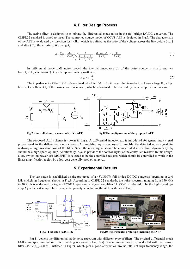
The active filter is designed to eliminate the differential mode noise in the full-bridge DC/DC converter. The CISPR22 standard is asked to meet. The controlled source model of CCVS AEF is depicted in Fig.7. The characteristic of the AEF is evaluated by insertion loss(IL)which is defined as the ratio of the voltage across the line before ( woU ) and after ( wU ) the insertion. We can get,
n n n r rn
rn n
n n
11 1wo
w n
U RZ i R Z B BIL i BU R Z R Z R ZR Z RZ
+ += = = = ++ + ++ +
(1)
In differential mode EMI noise model, the internal impedance nZ of the noise source is small, and we have nZ R , so equation (1) can be approximately written as,
r1DMBILR
≈ + (2) The impedance R of the LISN is determined which is 100Ω. So it means that in order to achieve a large IL, a big feedback coefficient rB of the noise current is in need, which is designed to be realized by the an amplifier in this case.
inR
is uc=-Bris
Zn
VCC
GNDQ
Fig.7 Controlled source model of CCVS AEF Fig.8 The configuration of the proposed AEF
The proposed AEF scheme is shown in Fig.8. A differential inductor DML is introduced for generating a signal proportional to the differential mode current. An amplifier A2 is employed to amplify the detected noise signal for realizing a large insertion loss of the filter. Since the noise signal should be compensated in real time dynamically, A2 should be a high-speed op-amp. Additionally, A2 also provides the control signal of the controlled resistor. In this design, a low switch-on power loss MOSFET is selected to be the controlled resistor, which should be controlled to work in the linear amplification region by a low cost generally used op-amp A1.
5. Experimental Results
The test setup is established on the prototype of a 48V/300W full-bridge DC/DC convertor operating at 240
kHz switching frequency, shown in Fig.9. According to CISPR 22 standards, the noise spectrum ranging from 150 kHz to 30 MHz is under test by Agilent E7401A spectrum analyser. Amplifier THS3062 is selected to be the high-speed op-amp A2 in the test setup. The experimental prototype including the AEF is shown in Fig.10.
1MV2MV 1VMV
2VMV
H50μ
H50μ
F1.0 μF1.0 μ
Ω50 Ω50
Ω50 Ω50
Fig.9 Test setup (CISPR22) Fig.10 Experimental prototype including the AEF
Fig.11 depicts the differential mode noise spectrum with different type of filters. The original differential mode
EMI noise spectrum without filter inserting is shown in Fig.10(a). Second measurement is conducted with the passive filter ( DMC=1uF,L =8uH as illustrated in Fig.7), which gets a good attenuation around 30dB at high frequency range, the
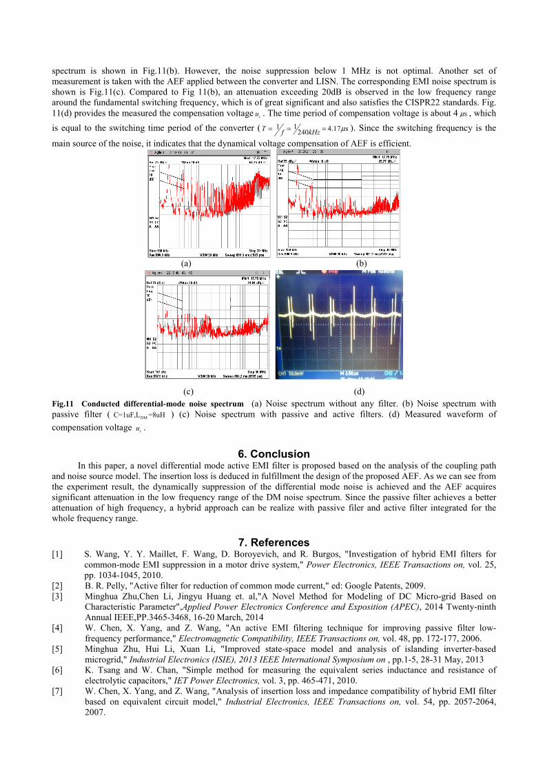
spectrum is shown in Fig.11(b). However, the noise suppression below 1 MHz is not optimal. Another set of measurement is taken with the AEF applied between the converter and LISN. The corresponding EMI noise spectrum is shown is Fig.11(c). Compared to Fig 11(b), an attenuation exceeding 20dB is observed in the low frequency range around the fundamental switching frequency, which is of great significant and also satisfies the CISPR22 standards. Fig. 11(d) provides the measured the compensation voltage cu . The time period of compensation voltage is about 4 sμ , which is equal to the switching time period of the converter ( 1 1 4.17 s240T f kHz μ= = = ). Since the switching frequency is the
main source of the noise, it indicates that the dynamical voltage compensation of AEF is efficient.
(a) (b)
(c) (d)
Fig.11 Conducted differential-mode noise spectrum (a) Noise spectrum without any filter. (b) Noise spectrum with passive filter ( DMC=1uF,L =8uH ) (c) Noise spectrum with passive and active filters. (d) Measured waveform of compensation voltage cu .
6. Conclusion In this paper, a novel differential mode active EMI filter is proposed based on the analysis of the coupling path and noise source model. The insertion loss is deduced in fulfillment the design of the proposed AEF. As we can see from the experiment result, the dynamically suppression of the differential mode noise is achieved and the AEF acquires significant attenuation in the low frequency range of the DM noise spectrum. Since the passive filter achieves a better attenuation of high frequency, a hybrid approach can be realize with passive filer and active filter integrated for the whole frequency range.
7. References [1] S. Wang, Y. Y. Maillet, F. Wang, D. Boroyevich, and R. Burgos, "Investigation of hybrid EMI filters for
common-mode EMI suppression in a motor drive system," Power Electronics, IEEE Transactions on, vol. 25, pp. 1034-1045, 2010.
[2] B. R. Pelly, "Active filter for reduction of common mode current," ed: Google Patents, 2009. [3] Minghua Zhu,Chen Li, Jingyu Huang et. al,"A Novel Method for Modeling of DC Micro-grid Based on
Characteristic Parameter",Applied Power Electronics Conference and Exposition (APEC), 2014 Twenty-ninth Annual IEEE,PP.3465-3468, 16-20 March, 2014
[4] W. Chen, X. Yang, and Z. Wang, "An active EMI filtering technique for improving passive filter low-frequency performance," Electromagnetic Compatibility, IEEE Transactions on, vol. 48, pp. 172-177, 2006.
[5] Minghua Zhu, Hui Li, Xuan Li, "Improved state-space model and analysis of islanding inverter-based microgrid," Industrial Electronics (ISIE), 2013 IEEE International Symposium on , pp.1-5, 28-31 May, 2013
[6] K. Tsang and W. Chan, "Simple method for measuring the equivalent series inductance and resistance of electrolytic capacitors," IET Power Electronics, vol. 3, pp. 465-471, 2010.
[7] W. Chen, X. Yang, and Z. Wang, "Analysis of insertion loss and impedance compatibility of hybrid EMI filter based on equivalent circuit model," Industrial Electronics, IEEE Transactions on, vol. 54, pp. 2057-2064, 2007.