Embed Size (px)
Citation preview
Design Manual - Post bases
I n n o v a t i v e w o o d c o n n e c t i o n s y s t e m s f o r h i g h e s t r e q u i r e m e n t s .
For further information: www.pitzl-connectors.com. Individual consulting: +49 8703 9346-0Page 2
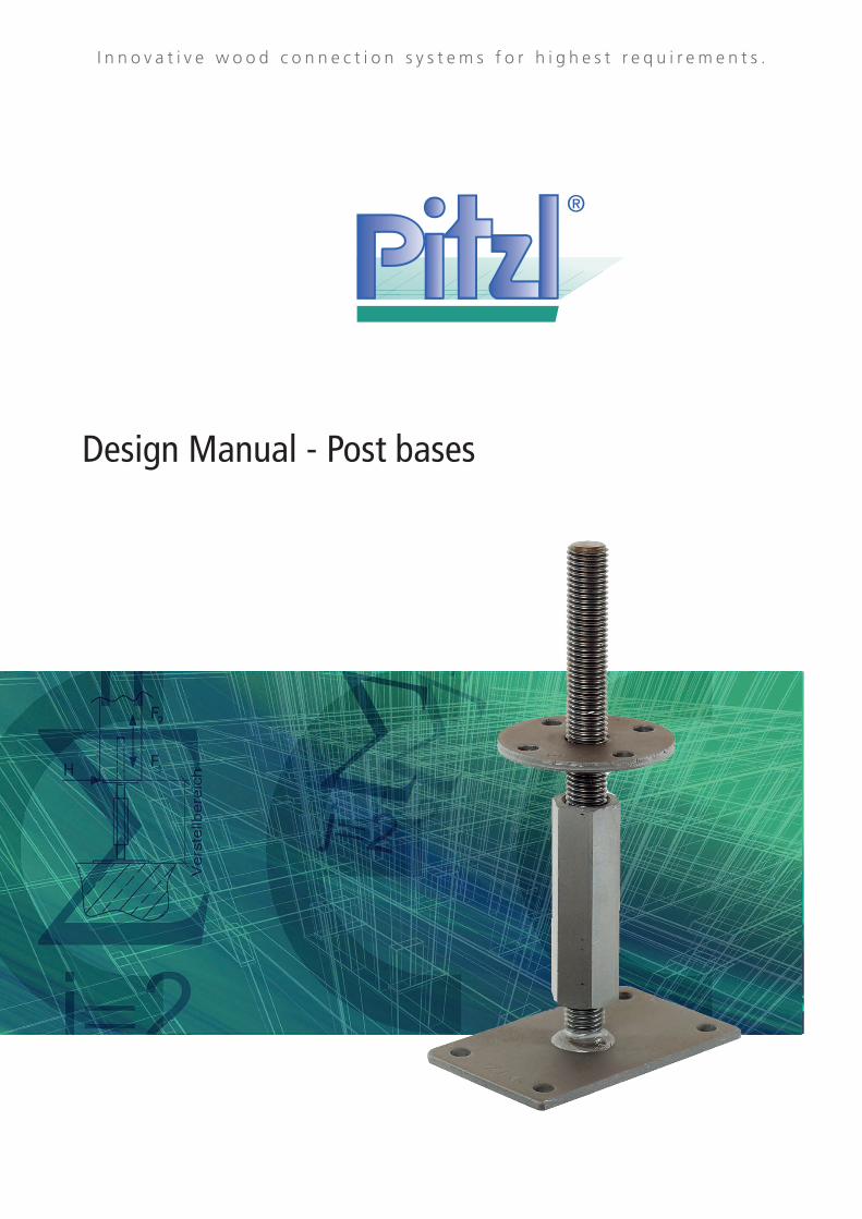
This is Pitzl
ETA-10/0413 European Technical ApprovalAll post bases and post-purlin connectors of Pitzl Metallbau GmbH & Co. KG have been approved through ETA -10/0413 Holder of approval:
Pitzl Metallbau GmbH & Co. KG, Siemensstraße 26, DE-84051 Altheim - Germany
Tel.: +49 (0) 8703 9346-0, Fax: +49 (0) 8703 9346-55, Internet: www.pitzl-connectors.comGeneric type and use of construction product:
Three-dimensional nailing plate (Post bases for the support of timber columns and Connectors for posts and purlins
as load-bearing elements as load-bearing elements)
(Valid from: 2013-05-09 to: 2018-05-09)Manufacturing plant:
Pitzl Metallbau GmbH & Co. KG, Siemensstraße 26, DE-84051 Altheim - Germany
As a provider of innovative wood connection systems for highest requirements, we are consistently trying to develop and optimise
our products further. The Pitzl range includes post bases, balcony and fence posts, plug-in connector systems as well as post-purlin
connections. Naturally, we also offer individual, custom-made solutions for your specific range of applications.
All Pitzl post bases and connectors can be used with screws from different manufacturers.
Welcome to the world of PITZL
Page 3
www.pitzl-connectors.com - Innovative wood connection systems for highest requirements.
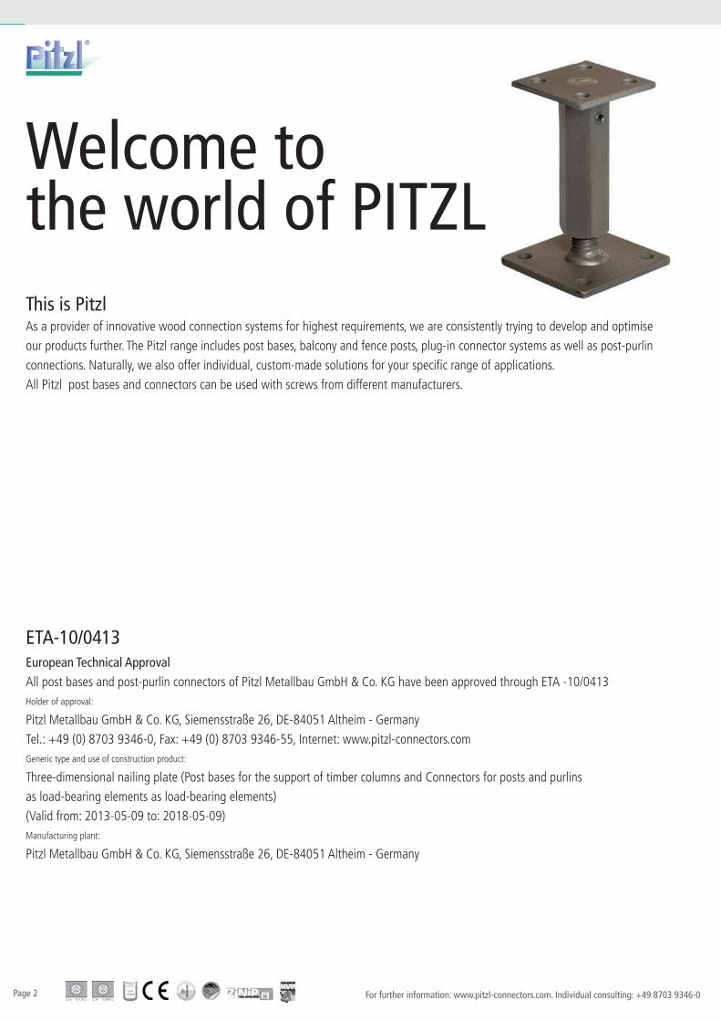
ContentsA/ Design values
1. General p.4
2. Design concept p.8
3. Design values of the post bases ETA-10/0413 (CE) p.11
3.1. System 10930/10931 p.11
3.2. Right/left thread p.15
3.3 Stainless steel V2A p.18
3.4 Heavy-duty version p.19
3.5 Threaded rod p.27
3.6 2 parts p.32
3.7 Rigid version, hot-dip galvanized p.38
3.8 For embedding in concrete p.40
4. Design values of the post-purlin connectors ETA-10/0413 (CE) p.43
5. Compressive load-carrying capacity of post bases following structural standards p.44
6. Design values of post bases, Plug-in system Z p.45
B/ Characteristic values
1. Characteristic load-carrying capacity of the post bases acc. to ETA-10/0413 (CE) p.46
2. Characteristic load-carrying capacity of the post bases acc. to Eurocode p.57
3. Characteristic load-carrying capacity of the post-purlin connectors acc. to ETA-10/0413 (CE) p.59
4. Characteristic load-carrying capacity of post bases, Plug-in system Z p.59
For further information: www.pitzl-connectors.com. Individual consulting: +49 8703 9346-0Page 4
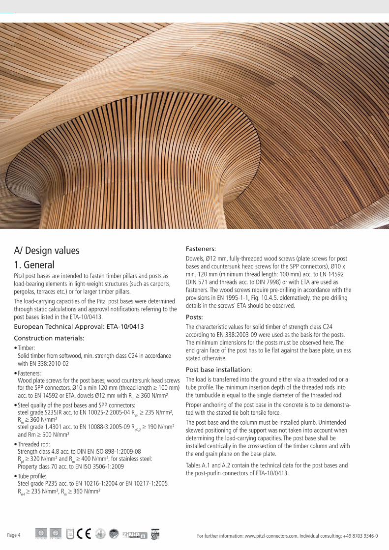
A/ Design values1. GeneralPitzl post bases are intended to fasten timber pillars and posts as load-bearing elements in light-weight structures (such as carports, pergolas, terraces etc.) or for larger timber pillars.
The load-carrying capacities of the Pitzl post bases were determined through static calculations and approval notifications referring to the post bases listed in the ETA-10/0413.
European Technical Approval: ETA-10/0413
Construction materials:
•Timber: Solid timber from softwood, min. strength class C24 in accordance with EN 338:2010-02
•Fasteners: Wood plate screws for the post bases, wood countersunk head screws for the SPP connectors, Ø10 x min 120 mm (thread length ≥ 100 mm) acc. to EN 14592 or ETA, dowels Ø12 mm with Rm ≥ 360 N/mm²
•SteelqualityofthepostbasesandSPPconnectors: steel grade S235JR acc. to EN 10025-2:2005-04 ReH ≥ 235 N/mm², Rm ≥ 360 N/mm² steel grade 1.4301 acc. to EN 10088-3:2005-09 Rp0,2 ≥ 190 N/mm² and Rm ≥ 500 N/mm²
•Threadedrod: Strength class 4.8 acc. to DIN EN ISO 898-1:2009-08 Rpf ≥ 320 N/mm² and Rm ≥ 400 N/mm², for stainless steel: Property class 70 acc. to EN ISO 3506-1:2009
•Tubeprofile: Steel grade P235 acc. to EN 10216-1:2004 or EN 10217-1:2005 ReH ≥ 235 N/mm², Rm ≥ 360 N/mm²
Fasteners:
Dowels, Ø12 mm, fully-threaded wood screws (plate screws for post bases and countersunk head screws for the SPP connectors), Ø10 x min. 120 mm (minimum thread length: 100 mm) acc. to EN 14592 (DIN 571 and threads acc. to DIN 7998) or with ETA are used as fasteners. The wood screws require pre-drilling in accordance with the provisions in EN 1995-1-1, Fig. 10.4.5. oldernatively, the pre-drilling details in the screws' ETA should be observed.
Posts:
The characteristic values for solid timber of strength class C24 according to EN 338:2003-09 were used as the basis for the posts. The minimum dimensions for the posts must be observed here. The end grain face of the post has to lie flat against the base plate, unless stated otherwise.
Post base installation:
The load is transferred into the ground either via a threaded rod or a tube profile. The minimum insertion depth of the threaded rods into the turnbuckle is equal to the single diameter of the threaded rod.
Proper anchoring of the post base in the concrete is to be demonstra-ted with the stated tie bolt tensile force.
The post base and the column must be installed plumb. Unintended skewed positioning of the support was not taken into account when determining the load-carrying capacities. The post base shall be installed centrically in the crosssection of the timber column and with the end grain plane on the base plate.
Tables A.1 and A.2 contain the technical data for the post bases and the post-purlin connectors of ETA-10/0413.
Page 5
www.pitzl-connectors.com - Innovative wood connection systems for highest requirements.
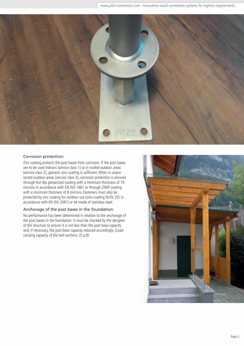
Corrosion protection:
Zinc coating protects the post bases from corrosion. If the post bases are to be used indoors (service class 1) or in roofed outdoor areas (service class 2), galvanic zinc coating is sufficient. When in unpro-tected outdoor areas (service class 3), corrosion protection is ensured through hot-dip galvanized coating with a minimum thickness of 70 microns in accordance with EN ISO 1461 or through ZiNiP coating with a minimum thickness of 8 microns. Fasteners must also be protected by zinc coating for outdoor use (zinc-coating Fe/Zn 25c in accordance with EN ISO 2081) or be made of stainless steel.
Anchorage of the post bases in the foundation:
No performance has been determined in relation to the anchorage of the post bases in the foundation. It must be checked by the designer of the structure to ensure it is not less than the post base capacity and, if necessary, the post base capacity reduced accordingly. (Load-carrying capacity of the bolt anchors: cf. p.9)
For further information: www.pitzl-connectors.com. Individual consulting: +49 8703 9346-0Page 6
Post bases - Design Manual
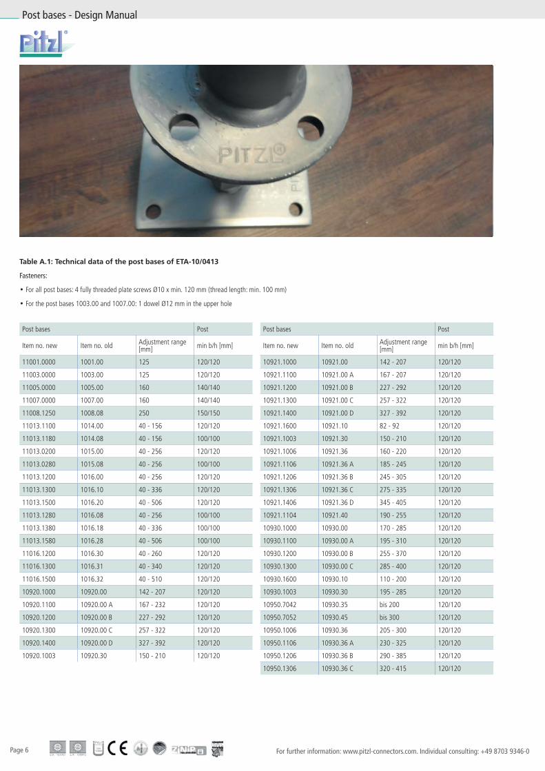
Table A.1: Technical data of the post bases of ETA-10/0413
Fasteners:
• For all post bases: 4 fully threaded plate screws Ø10 x min. 120 mm (thread length: min. 100 mm)
• For the post bases 1003.00 and 1007.00: 1 dowel Ø12 mm in the upper hole
Post bases Post
Item no. new Item no. old Adjustment range [mm] min b/h [mm]
11001.0000 1001.00 125 120/120
11003.0000 1003.00 125 120/120
11005.0000 1005.00 160 140/140
11007.0000 1007.00 160 140/140
11008.1250 1008.08 250 150/150
11013.1100 1014.00 40 - 156 120/120
11013.1180 1014.08 40 - 156 100/100
11013.0200 1015.00 40 - 256 120/120
11013.0280 1015.08 40 - 256 100/100
11013.1200 1016.00 40 - 256 120/120
11013.1300 1016.10 40 - 336 120/120
11013.1500 1016.20 40 - 506 120/120
11013.1280 1016.08 40 - 256 100/100
11013.1380 1016.18 40 - 336 100/100
11013.1580 1016.28 40 - 506 100/100
11016.1200 1016.30 40 - 260 120/120
11016.1300 1016.31 40 - 340 120/120
11016.1500 1016.32 40 - 510 120/120
10920.1000 10920.00 142 - 207 120/120
10920.1100 10920.00 A 167 - 232 120/120
10920.1200 10920.00 B 227 - 292 120/120
10920.1300 10920.00 C 257 - 322 120/120
10920.1400 10920.00 D 327 - 392 120/120
10920.1003 10920.30 150 - 210 120/120
Post bases Post
Item no. new Item no. old Adjustment range [mm] min b/h [mm]
10921.1000 10921.00 142 - 207 120/120
10921.1100 10921.00 A 167 - 207 120/120
10921.1200 10921.00 B 227 - 292 120/120
10921.1300 10921.00 C 257 - 322 120/120
10921.1400 10921.00 D 327 - 392 120/120
10921.1600 10921.10 82 - 92 120/120
10921.1003 10921.30 150 - 210 120/120
10921.1006 10921.36 160 - 220 120/120
10921.1106 10921.36 A 185 - 245 120/120
10921.1206 10921.36 B 245 - 305 120/120
10921.1306 10921.36 C 275 - 335 120/120
10921.1406 10921.36 D 345 - 405 120/120
10921.1104 10921.40 190 - 255 120/120
10930.1000 10930.00 170 - 285 120/120
10930.1100 10930.00 A 195 - 310 120/120
10930.1200 10930.00 B 255 - 370 120/120
10930.1300 10930.00 C 285 - 400 120/120
10930.1600 10930.10 110 - 200 120/120
10930.1003 10930.30 195 - 285 120/120
10950.7042 10930.35 bis 200 120/120
10950.7052 10930.45 bis 300 120/120
10950.1006 10930.36 205 - 300 120/120
10950.1106 10930.36 A 230 - 325 120/120
10950.1206 10930.36 B 290 - 385 120/120
10950.1306 10930.36 C 320 - 415 120/120
Page 7
www.pitzl-connectors.com - Innovative wood connection systems for highest requirements.
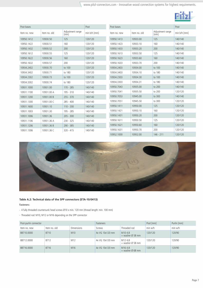
Table A.2: Technical data of the SPP connectors (ETA-10/0413)
Fasteners:
- 4 fully threaded countersunk head screws Ø10 x min. 120 mm (thread length: min. 100 mm)
- Threaded rod: M10, M12 or M16 depending on the SPP connector
Post-purlin connector Fasteners Post [mm] Purlin [mm]
Item no. new Item no. old Dimensions Screws Threaded rod min w/h min w/h
88710.0000 8710 M10 4x VG 10x120 mm M10 4.8 + washer Ø 58 mm
120/120 120/90
88712.0000 8712 M12 4x VG 10x120 mm M12 4.8 + washer Ø 58 mm
120/120 120/90
88716.0000 8716 M16 4x VG 10x120 mm M16 4.8 + washer Ø 68 mm
120/120 120/90
Post bases Post
Item no. new Item no. old Adjustment range [mm] min b/h [mm]
10950.1412 10930.50 125 120/120
10950.1422 10930.51 160 120/120
10950.1432 10930.52 200 120/120
10950.1612 10930.55 125 120/120
10950.1622 10930.56 160 120/120
10950.1632 10930.57 200 120/120
10934.2402 10930.70 to 100 120/120
10934.3402 10930.71 to 180 120/120
10934.2302 10930.73 to 100 120/120
10934.3302 10930.74 to 180 120/120
10931.1000 10931.00 170 - 285 140/140
10931.1100 10931.00 A 195 - 310 140/140
10931.1200 10931.00 B 255 - 370 140/140
10931.1300 10931.00 C 285 - 400 140/140
10931.1600 10931.10 110 - 200 140/140
10931.1003 10931.30 195 - 285 140/140
10931.1006 10931.36 205 - 300 140/140
10931.1106 10931.36 A 230 - 325 140/140
10931.1206 10931.36 B 290 - 385 140/140
10931.1306 10931.36 C 320 - 415 140/140
Post bases Post
Item no. new Item no. old Adjustment range [mm] min b/h [mm]
10950.1413 10933.00 125 140/140
10950.1423 10933.10 160 140/140
10950.1433 10933.20 200 140/140
10950.1613 10933.50 125 140/140
10950.1623 10933.60 160 140/140
10950.1633 10933.70 200 140/140
10934.2403 10934.00 to 100 140/140
10934.3403 10934.10 to 180 140/140
10934.2303 10934.30 to 100 140/140
10934.3303 10934.31 to 180 140/140
10950.7043 10935.00 to 200 140/140
10950.7041 10935.50 to 200 120/120
10950.7053 10945.00 to 300 140/140
10950.7051 10945.50 to 300 120/120
10950.1411 10950.00 125 120/120
10950.1421 10950.10 160 120/120
10950.1431 10950.20 200 120/120
10950.1611 10950.50 125 120/120
10950.1621 10950.60 160 120/120
10950.1631 10950.70 200 120/120
10952.1000 10952.00 146 - 211 120/120
For further information: www.pitzl-connectors.com. Individual consulting: +49 8703 9346-0Page 8
Post bases - Design Manual
2. Design conceptPost bases by Pitzl must be designed in accordance with the applicable timber and steel construction standards Eurocode 5 and Eurocode 3 or with an equivalent national code.
The following design values for the load-carrying capacity were determined in accordance with the European standards Eurocode 5: “Design of timber structures” (EN 1995-1-1:2010-12) and Eurocode 3 “Design of steel structures” (EN 1993-1:2010-12), which means they reflect the current state of technology regarding safety concept, cross-section determination and design.
The characteristic loads on the load side are increased by partial safety factors (γG = 1,35 for constant loads, γQ = 1,5 for variable loads). While on the resistance side, the characteristic load-carrying capacities are reduced by dividing through the partial safety coefficient γM.
where:
(basic combination) acc. to EN 1990
Page 9
www.pitzl-connectors.com - Innovative wood connection systems for highest requirements.
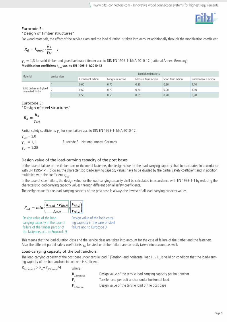
Eurocode 5: "Design of timber structures"
For wood materials, the effect of the service class and the load duration is taken into account additionally through the modification coefficient
γM = 1,3 for solid timber and glued laminated timber acc. to DIN EN 1995-1-1/NA:2010-12 (national Annex: Germany)Modification coefficient kmod acc. to EN 1995-1-1:2010-12
Material service classLoad duration class
Permanent action Long term action Medium term action Short term action instantaneous action
Solid timber and glued laminated timber
1 0,60 0,70 0,80 0,90 1,10
2 0,60 0,70 0,80 0,90 1,10
3 0,50 0,55 0,65 0,70 0,90
Eurocode 3: "Design of steel structures"
Partial safety coefficients γM for steel failure acc. to DIN EN 1993-1-1/NA:2010-12:
γM0 = 1,0γM1 = 1,1 Eurocode 3 - National Annex: Germany
γM2 = 1,25
Design value of the load-carrying capacity of the post bases:
In the case of failure of the timber part or the metal fasteners, the design value for the load-carrying capacity shall be calculated in accordance with EN 1995-1-1. To do so, the characteristic load-carrying capacity values have to be divided by the partial safety coefficient and in addition multiplied with the coefficient kmod.
In the case of steel failure, the design value for the load-carrying capacity shall be calculated in accordance with EN 1993-1-1 by reducing the characteristic load-carrying capacity values through different partial safety coefficients.
The design value for the load-carrying capacity of the post base is always the lowest of all load-carrying capacity values.
Design value of the load-carrying capacity in the case of failure of the timber part or of the fasteners acc. to Eurocode 5
Design value of the load-carry-ing capacity in the case of steel failure acc. to Eurocode 3
This means that the load-duration class and the service class are taken into account for the case of failure of the timber and the fasteners. Also, the different partial safety coefficients γM for steel or timber failure are correctly taken into account, as well.
Load-carrying capacity of the bolt anchors:
The load-carrying capacity of the post base under tensile load F (Tension) and horizontal load H1 / H2 is valid on condition that the load-carry-ing capacity of the bolt anchors in concrete is sufficient.
RAnchor,ax,d > FA+Fd,Tension /4 where:
RAnchor,ax,d Design value of the tensile load-carrying capacity per bolt anchor
FA Tensile force per bolt anchor under horizontal load
Fd, Tension Design value of the tensile load of the post base
For further information: www.pitzl-connectors.com. Individual consulting: +49 8703 9346-0Page 10
Post bases - Design Manual
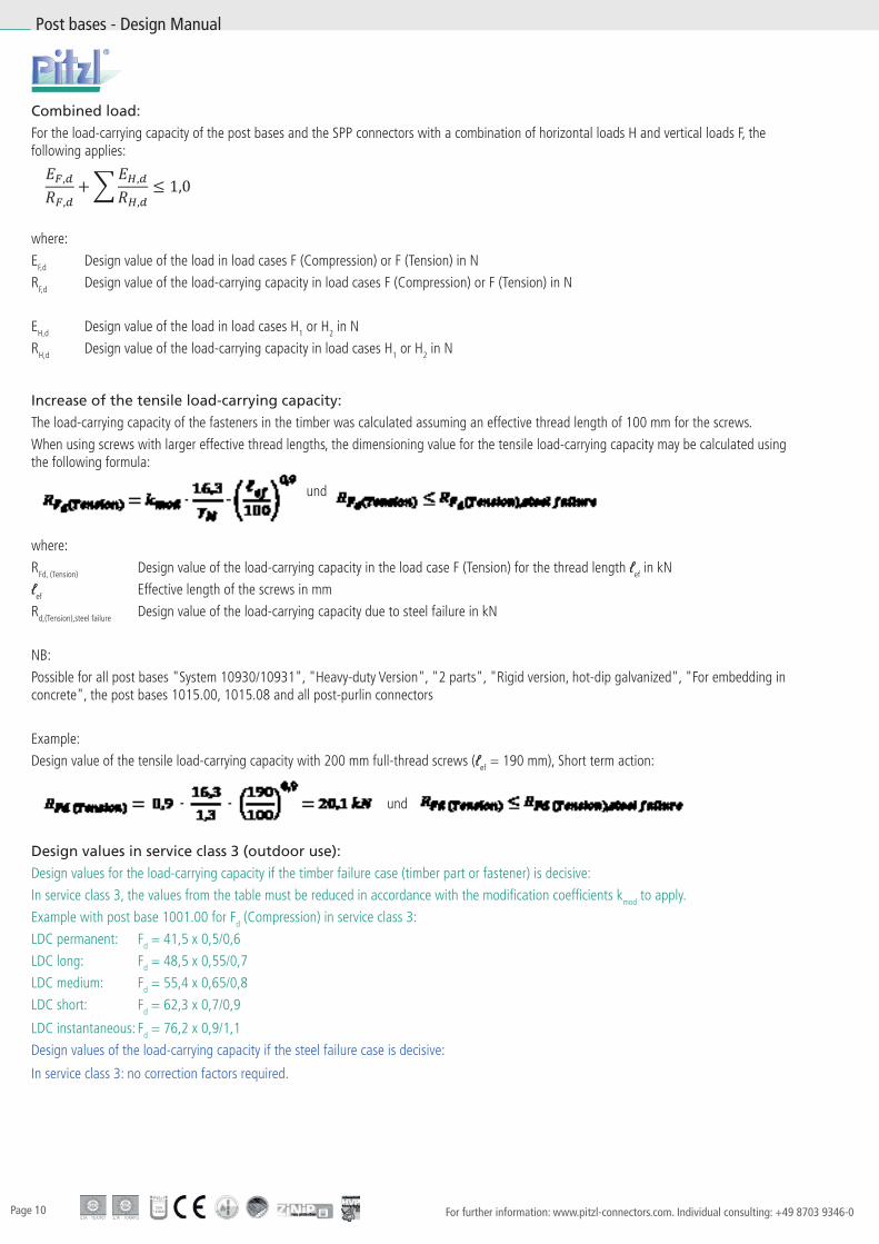
Combined load:
For the load-carrying capacity of the post bases and the SPP connectors with a combination of horizontal loads H and vertical loads F, the following applies:
where:
EF,d Design value of the load in load cases F (Compression) or F (Tension) in N
RF,d Design value of the load-carrying capacity in load cases F (Compression) or F (Tension) in N
EH,d Design value of the load in load cases H1 or H2 in N
RH,d Design value of the load-carrying capacity in load cases H1 or H2 in N
Increase of the tensile load-carrying capacity:
The load-carrying capacity of the fasteners in the timber was calculated assuming an effective thread length of 100 mm for the screws.
When using screws with larger effective thread lengths, the dimensioning value for the tensile load-carrying capacity may be calculated using the following formula:
und
where:
RFd, (Tension) Design value of the load-carrying capacity in the load case F (Tension) for the thread length ℓef in kN
ℓef Effective length of the screws in mm
Rd,(Tension),steel failure Design value of the load-carrying capacity due to steel failure in kN
NB:
Possible for all post bases "System 10930/10931", "Heavy-duty Version", "2 parts", "Rigid version, hot-dip galvanized", "For embedding in concrete", the post bases 1015.00, 1015.08 and all post-purlin connectors
Example:
Design value of the tensile load-carrying capacity with 200 mm full-thread screws (ℓef = 190 mm), Short term action:
und
Design values in service class 3 (outdoor use):
Design values for the load-carrying capacity if the timber failure case (timber part or fastener) is decisive:
In service class 3, the values from the table must be reduced in accordance with the modification coefficients kmod to apply.
Example with post base 1001.00 for Fd (Compression) in service class 3:
LDC permanent: Fd = 41,5 x 0,5/0,6
LDC long: Fd = 48,5 x 0,55/0,7
LDC medium: Fd = 55,4 x 0,65/0,8
LDC short: Fd = 62,3 x 0,7/0,9
LDC instantaneous: Fd = 76,2 x 0,9/1,1
Design values of the load-carrying capacity if the steel failure case is decisive:
In service class 3: no correction factors required.
Page 11
www.pitzl-connectors.com - Innovative wood connection systems for highest requirements.
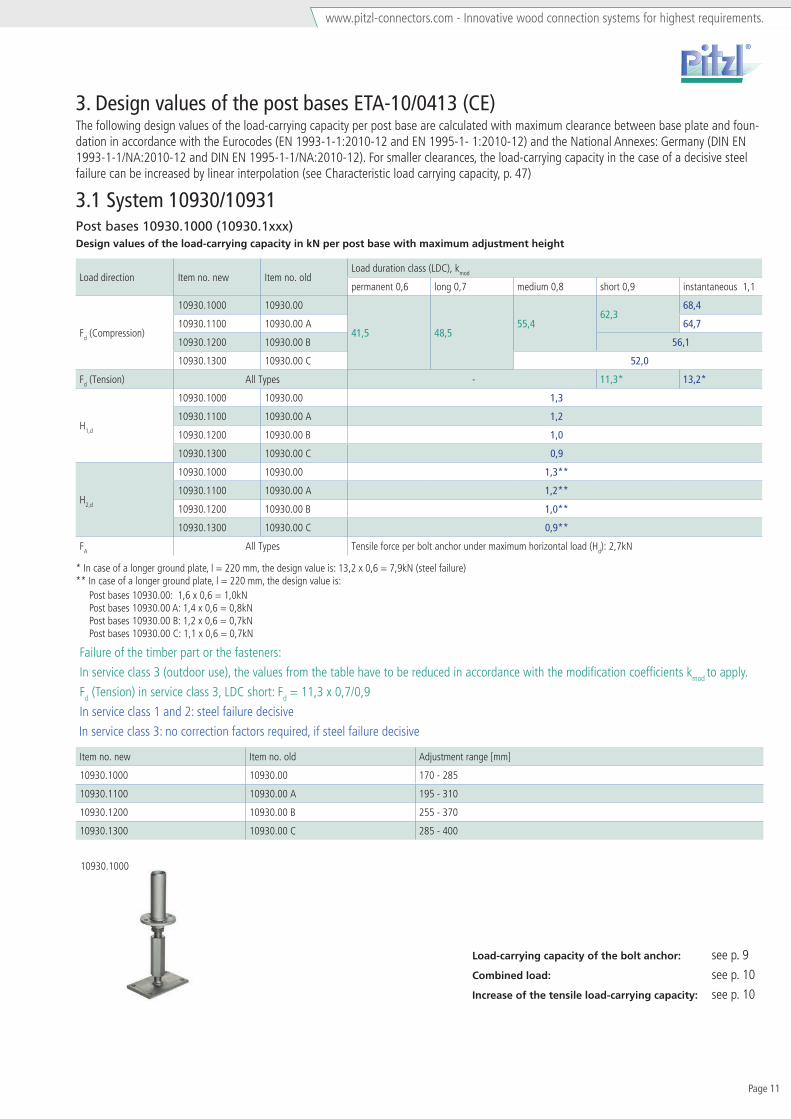
3. Design values of the post bases ETA-10/0413 (CE)The following design values of the load-carrying capacity per post base are calculated with maximum clearance between base plate and foun-dation in accordance with the Eurocodes (EN 1993-1-1:2010-12 and EN 1995-1- 1:2010-12) and the National Annexes: Germany (DIN EN 1993-1-1/NA:2010-12 and DIN EN 1995-1-1/NA:2010-12). For smaller clearances, the load-carrying capacity in the case of a decisive steel failure can be increased by linear interpolation (see Characteristic load carrying capacity, p. 47)
3.1 System 10930/10931Post bases 10930.1000 (10930.1xxx)Design values of the load-carrying capacity in kN per post base with maximum adjustment height
Load direction Item no. new Item no. oldLoad duration class (LDC), kmod
permanent 0,6 long 0,7 medium 0,8 short 0,9 instantaneous 1,1
Fd (Compression)
10930.1000 10930.00
41,5 48,555,4
62,368,4
10930.1100 10930.00 A 64,7
10930.1200 10930.00 B 56,1
10930.1300 10930.00 C 52,0
Fd (Tension) All Types - 11,3* 13,2*
H1,d
10930.1000 10930.00 1,3
10930.1100 10930.00 A 1,2
10930.1200 10930.00 B 1,0
10930.1300 10930.00 C 0,9
H2,d
10930.1000 10930.00 1,3**
10930.1100 10930.00 A 1,2**
10930.1200 10930.00 B 1,0**
10930.1300 10930.00 C 0,9**
FA All Types Tensile force per bolt anchor under maximum horizontal load (Hd): 2,7kN
* In case of a longer ground plate, l = 220 mm, the design value is: 13,2 x 0,6 = 7,9kN (steel failure) ** In case of a longer ground plate, l = 220 mm, the design value is: Post bases 10930.00: 1,6 x 0,6 = 1,0kN Post bases 10930.00 A: 1,4 x 0,6 = 0,8kN Post bases 10930.00 B: 1,2 x 0,6 = 0,7kN Post bases 10930.00 C: 1,1 x 0,6 = 0,7kN
Failure of the timber part or the fasteners:
In service class 3 (outdoor use), the values from the table have to be reduced in accordance with the modification coefficients kmod to apply.
Fd (Tension) in service class 3, LDC short: Fd = 11,3 x 0,7/0,9
In service class 1 and 2: steel failure decisive
In service class 3: no correction factors required, if steel failure decisive
Item no. new Item no. old Adjustment range [mm]
10930.1000 10930.00 170 - 285
10930.1100 10930.00 A 195 - 310
10930.1200 10930.00 B 255 - 370
10930.1300 10930.00 C 285 - 400
10930.1000
Load-carrying capacity of the bolt anchor: see p. 9
Combined load: see p. 10
Increase of the tensile load-carrying capacity: see p. 10
For further information: www.pitzl-connectors.com. Individual consulting: +49 8703 9346-0Page 12
Post bases - Design Manual
Post bases 10930.1600:
Design values of the load-carrying capacity in kN per post base with maximum adjustment height
Load direction Item no. new Item no. oldLoad duration class (LDC), kmod
permanent 0,6 long 0,7 medium 0,8 short 0,9 instantaneous 1,1
Fd (Compression)
10930.1600 10930.10
41,5 48,5 55,4 62,3 76,2
Fd (Tension) - 11,3* 13,2*
H1,d 1,8
H2,d 1,8**
FA Tensile force per bolt anchor under maximum horizontal load (Hd): 2,6kN
* In case of a longer ground plate, l = 220 mm, the design value is: 13,2 x 0,6 = 7,9kN (steel failure) ** In case of a longer ground plate, l = 220 mm, the design value is: 2,2 x 0,6 = 1,3kN
Failure of the timber part or the fasteners:
In service class 3 (outdoor use), the values from the table have to be reduced in accordance with the modification coefficients kmod to apply.
Fd (Compression) in service class 3, LDC short: Fd = 62,3 x 0,7/0,9
In service class 1 and 2: steel failure decisive
In service class 3: no correction factors required, if steel failure decisive
Item no. new Item no. old Adjustment range [mm]
10930.1600 10930.10 110 - 200
10930.1600
Page 13
www.pitzl-connectors.com - Innovative wood connection systems for highest requirements.
Post bases 10931.1000 (10931.1xxx):
Design values of the load-carrying capacity in kN per post base with maximum adjustment height:
Load direction Item no. new Item no. oldLoad duration class (LDC), kmod
permanent 0,6 long 0,7 medium 0,8 short 0,9 instantaneous 1,1
Fd (Compression)
10931.1000 10931.00
41,5 48,555,4
62,368,4
10931.1100 10931.00 A 64,7
10931.1200 10931.00 B 56,1
10931.1300 10931.00 C 52,0
Fd (Tension) All Types - 11,3* 13,2*
H1,d
10931.1000 10931.00 1,3
10931.1100 10931.00 A 1,2
10931.1200 10931.00 B 1,0
10931.1300 10931.00 C 0,9
H2,d
10931.1000 10931.00 1,3**
10931.1100 10931.00 A 1,2**
10931.1200 10931.00 B 1,0**
10931.1300 10931.00 C 0,9**
FA All Types Tensile force per bolt anchor under maximum horizontal load (Hd): 2,7kN
* In case of a longer ground plate, l = 220 mm, the design value is: 1,32 x 0,6 = 7,9kN (steel failure) ** In case of a longer ground plate, l = 220 mm, the design value is: Post bases 10930.00: 1,6 x 0,6 = 1,0kN Post bases 10930.00 A: 1,4 x 0,6 = 0,8kN Post bases 10930.00 B: 1,2 x 0,6 = 0,7kN Post bases 10930.00 C: 1,1 x 0,6 = 0,7kN
Failure of the timber part or the fasteners:
In service class 3 (outdoor use), the values from the table have to be reduced in accordance with the modification coefficients kmod to apply.
Fd (Tension) in service class 3, LDC short: Fd = 11,3 x 0,7/0,9
In service class 1 and 2: steel failure decisive
In service class 3: no correction factors required, if steel failure decisive
Item no. new Item no. old Adjustment range [mm]
10931.1000 10931.00 170 - 285
10931.1100 10931.00 A 195 - 310
10931.1200 10931.00 B 255 - 370
10931.1300 10931.00 C 285 - 400
10931.1000
Load-carrying capacity of the bolt anchor: see p. 9
Combined load: see p. 10
Increase of the tensile load-carrying capacity: see p. 10
For further information: www.pitzl-connectors.com. Individual consulting: +49 8703 9346-0Page 14
Post bases - Design Manual
Post bases 10931.1600:
Design values of the load-carrying capacity in kN per post base with maximum adjustment height
Load direction Item no. new Item no. newLoad duration class (LDC), kmod
permanent 0,6 long 0,7 medium 0,8 short 0,9 instantaneous 1,1
Fd (Compression)
10931.10 10931.1600
41,5 48,5 55,4 62,3 76,2
Fd (Tension) - 11,3* 13,2*
H1,d 1,8
H2,d 1,8**
FA Tensile force per bolt anchor under maximum horizontal load (Hd): 2,6kN
* In case of a longer ground plate l = 220 mm, the design value is: 13,2 x 0,6 = 7,9kN (steel failure) ** In case of a longer ground plate, l = 220 mm, the design value is: 1,3kN
Failure of the timber part or the fasteners:
In service class 3 (outdoor use), the values from the table have to be reduced in accordance with the modification coefficients kmod to apply.
Fd (Compression) in service class 3, LDC short: Fd = 62,3 x 0,7/0,9
In service class 1 and 2: steel failure decisive
In service class 3: no correction factors required, if steel failure decisive
Item no. new Item no. old Adjustment range [mm]
10931.1600 10931.10 110 - 200
10931.1600
Load-carrying capacity of the bolt anchor: see p. 9
Combined load: see p. 10
Increase of the tensile load-carrying capacity: see p. 10
Page 15
www.pitzl-connectors.com - Innovative wood connection systems for highest requirements.
3.2 Right/left threadPost bases 10920.1000 (10920.1xxx):Design values of the load-carrying capacity in kN per post base with maximum adjustment height
Load direction Item no. new Item no. oldLoad duration class (LDC), kmod
permanent 0,6 long 0,7 medium 0,8 short 0,9 instantaneous 1,1
Fd (Compression)
10920.1000 10920.00
41,5 48,555,4 62,3
76,210920.1100 10920.00 A
10920.1200 10920.00 B 67,8
10920.1300 10920.00 C 63,5
10920.1400 10920.00 D 53,5
Fd (Tension) All Types - 7,4*
H1,d
10920.1000 10920.00 1,8
10920.1100 10920.00 A 1,6
10920.1200 10920.00 B 1,3
10920.1300 10920.00 C 1,1
10920.1400 10920.00 D 1,0
H2,d
10920.1000 10920.00 1,2*
10920.1100 10920.00 A 1,1*
10920.1200 10920.00 B 0,9*
10920.1300 10920.00 C 0,8*
10920.1400 10920.00 D 0,6*
FA
10920.1000 10920.00
Tensile force per bolt anchor under maximum horizontal load (Hd): 2,7kN10920.1100 10920.00 A
10920.1200 10920.00 B
10920.1300 10920.00 C Tensile force per bolt anchor under maximum horizontal load (Hd): 2,5kN
10920.1400 10920.00 D Tensile force per bolt anchor under maximum horizontal load (Hd): 3,1kN
* In case of a longer ground plate, l = 220mm, the values must be reduced by the factor 0.6
Failure of the timber part or the fasteners:
In service class 3 (outdoor use), the values from the table have to be reduced in accordance with the modification coefficients kmod to apply.
Post bases 10920.00/A/B/C: Fd (Compression) in service class 3, LDC short: Fd = 62,3 x 0,7/0,9
In service class 1 and 2: steel failure decisive
In service class 3: no correction factors required, if steel failure decisive
Item no. new Item no. old Adjustment range [mm]
10920.1000 10920.00 142 - 207
10920.1100 10920.00 A 167 - 232
10920.1200 10920.00 B 227 - 292
10920.1300 10920.00 C 257 - 322
10920.1400 10920.00 D 327 - 392
10920.1000
For further information: www.pitzl-connectors.com. Individual consulting: +49 8703 9346-0Page 16
Post bases - Design Manual
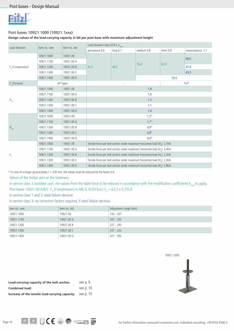
Post bases 10921.1000 (10921.1xxx):Design values of the load-carrying capacity in kN per post base with maximum adjustment height
Load direction Item no. new Item no. oldLoad duration class (LDC), kmod
permanent 0,6 long 0,7 medium 0,8 short 0,9 instantaneous 1,1
Fd (Compression)
10921.1000 10921.00
41,5 48,555,4 62,3
68,610921.1100 10921.00 A
10921.1200 10921.00 B 67,8
10921.1300 10921.00 C 63,5
10921.1400 10921.00 D 53,5
Fd (Tension) All Types - 7,4*
H1,d
10921.1000 10921.00 1,8
10921.1100 10921.00 A 1,6
10921.1200 10921.00 B 1,3
10921.1300 10921.00 C 1,1
10921.1400 10921.00 D 1,0
H2,d
10921.1000 10921.00 1,2*
10921.1100 10921.00 A 1,1*
10921.1200 10921.00 B 0,9*
10921.1300 10921.00 C 0,8*
10921.1400 10921.00 D 0,6*
FA
10921.1000 10921.00 Tensile force per bolt anchor under maximum horizontal load (Hd): 2,7kN
10921.1100 10921.00 A Tensile force per bolt anchor under maximum horizontal load (Hd): 2,4kN
10921.1200 10921.00 B Tensile force per bolt anchor under maximum horizontal load (Hd): 2,2kN
10921.1300 10921.00 C Tensile force per bolt anchor under maximum horizontal load (Hd): 2,3kN
10921.1400 10921.00 D Tensile force per bolt anchor under maximum horizontal load (Hd): 2,8kN
* In case of a longer ground plate, l = 220 mm, the values must be reduced by the factor 0.6
Failure of the timber part or the fasteners:
In service class 3 (outdoor use), the values from the table have to be reduced in accordance with the modification coefficients kmod to apply.
Post bases 10921.00 A/B/C: Fd (Compression) in NKL3, KLED kurz: Fd = 62,3 x 0,7/0,9
In service class 1 and 2: steel failure decisive
In service class 3: no correction factors required, if steel failure decisive
Item no. new Item no. old Adjustment range [mm]
10921.1000 10921.00 142 - 207
10921.1100 10921.00 A 167 - 232
10921.1200 10921.00 B 227 - 292
10921.1300 10921.00 C 257 - 322
10921.1400 10921.00 D 327 - 392
10921.1000
Load-carrying capacity of the bolt anchor: see p. 9
Combined load: see p. 10
Increase of the tensile load-carrying capacity: see p. 10
Page 17
www.pitzl-connectors.com - Innovative wood connection systems for highest requirements.
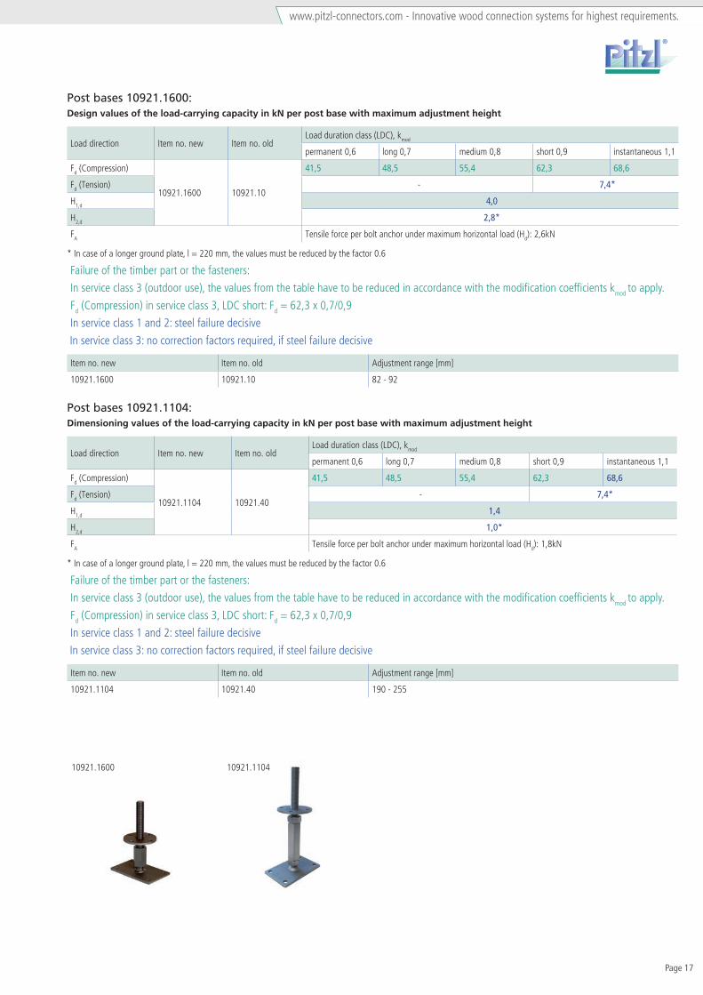
Post bases 10921.1600:Design values of the load-carrying capacity in kN per post base with maximum adjustment height
Load direction Item no. new Item no. oldLoad duration class (LDC), kmod
permanent 0,6 long 0,7 medium 0,8 short 0,9 instantaneous 1,1
Fd (Compression)
10921.1600 10921.10
41,5 48,5 55,4 62,3 68,6
Fd (Tension) - 7,4*
H1,d 4,0
H2,d 2,8*
FA Tensile force per bolt anchor under maximum horizontal load (Hd): 2,6kN
* In case of a longer ground plate, l = 220 mm, the values must be reduced by the factor 0.6
Failure of the timber part or the fasteners:
In service class 3 (outdoor use), the values from the table have to be reduced in accordance with the modification coefficients kmod to apply.
Fd (Compression) in service class 3, LDC short: Fd = 62,3 x 0,7/0,9
In service class 1 and 2: steel failure decisive
In service class 3: no correction factors required, if steel failure decisive
Item no. new Item no. old Adjustment range [mm]
10921.1600 10921.10 82 - 92
Post bases 10921.1104:Dimensioning values of the load-carrying capacity in kN per post base with maximum adjustment height
Load direction Item no. new Item no. oldLoad duration class (LDC), kmod
permanent 0,6 long 0,7 medium 0,8 short 0,9 instantaneous 1,1
Fd (Compression)
10921.1104 10921.40
41,5 48,5 55,4 62,3 68,6
Fd (Tension) - 7,4*
H1,d 1,4
H2,d 1,0*
FA Tensile force per bolt anchor under maximum horizontal load (Hd): 1,8kN
* In case of a longer ground plate, l = 220 mm, the values must be reduced by the factor 0.6
Failure of the timber part or the fasteners:
In service class 3 (outdoor use), the values from the table have to be reduced in accordance with the modification coefficients kmod to apply.
Fd (Compression) in service class 3, LDC short: Fd = 62,3 x 0,7/0,9
In service class 1 and 2: steel failure decisive
In service class 3: no correction factors required, if steel failure decisive
Item no. new Item no. old Adjustment range [mm]
10921.1104 10921.40 190 - 255
10921.1600 10921.1104
For further information: www.pitzl-connectors.com. Individual consulting: +49 8703 9346-0Page 18
Post bases - Design Manual
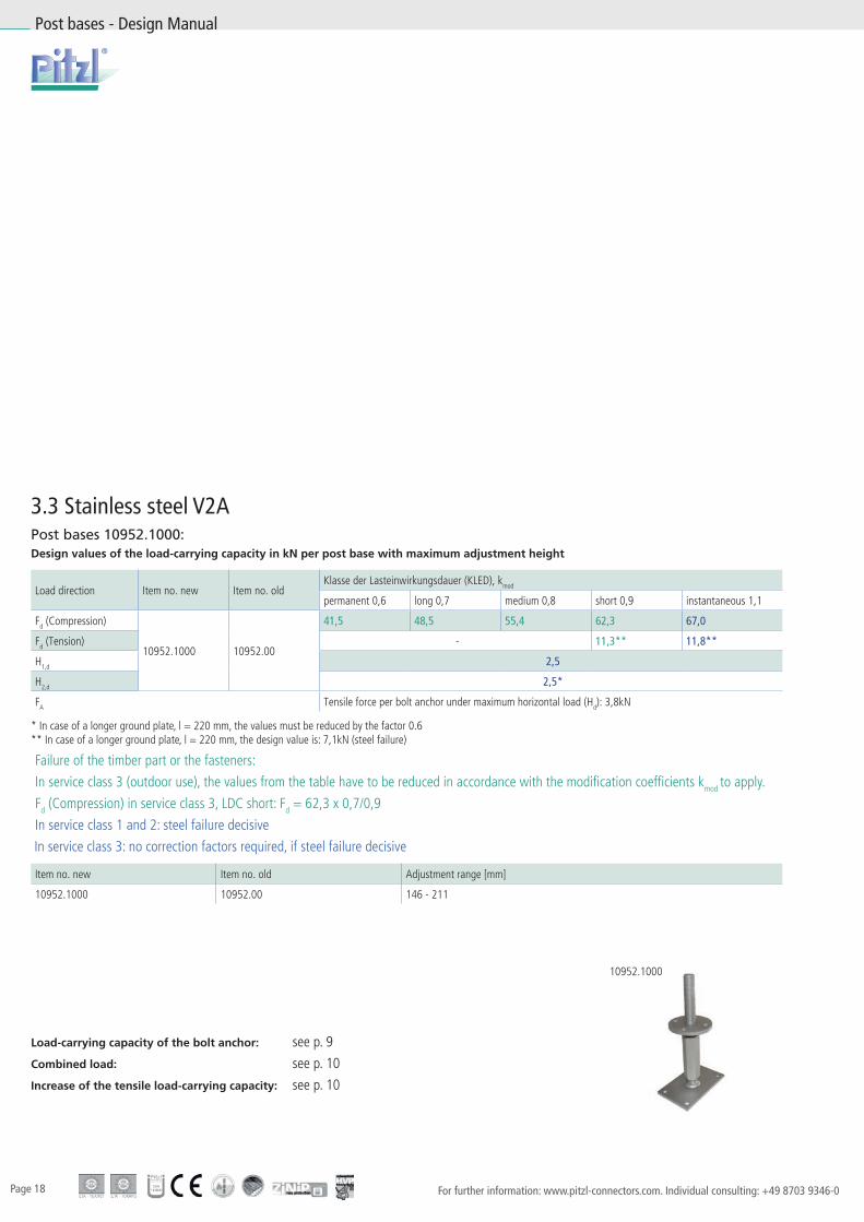
3.3 Stainless steel V2APost bases 10952.1000:Design values of the load-carrying capacity in kN per post base with maximum adjustment height
Load direction Item no. new Item no. oldKlasse der Lasteinwirkungsdauer (KLED), kmod
permanent 0,6 long 0,7 medium 0,8 short 0,9 instantaneous 1,1
Fd (Compression)
10952.1000 10952.00
41,5 48,5 55,4 62,3 67,0
Fd (Tension) - 11,3** 11,8**
H1,d 2,5
H2,d 2,5*
FA Tensile force per bolt anchor under maximum horizontal load (Hd): 3,8kN
* In case of a longer ground plate, l = 220 mm, the values must be reduced by the factor 0.6 ** In case of a longer ground plate, l = 220 mm, the design value is: 7,1kN (steel failure)
Failure of the timber part or the fasteners:
In service class 3 (outdoor use), the values from the table have to be reduced in accordance with the modification coefficients kmod to apply.
Fd (Compression) in service class 3, LDC short: Fd = 62,3 x 0,7/0,9
In service class 1 and 2: steel failure decisive
In service class 3: no correction factors required, if steel failure decisive
Item no. new Item no. old Adjustment range [mm]
10952.1000 10952.00 146 - 211
10952.1000
Load-carrying capacity of the bolt anchor: see p. 9
Combined load: see p. 10
Increase of the tensile load-carrying capacity: see p. 10
Page 19
www.pitzl-connectors.com - Innovative wood connection systems for highest requirements.
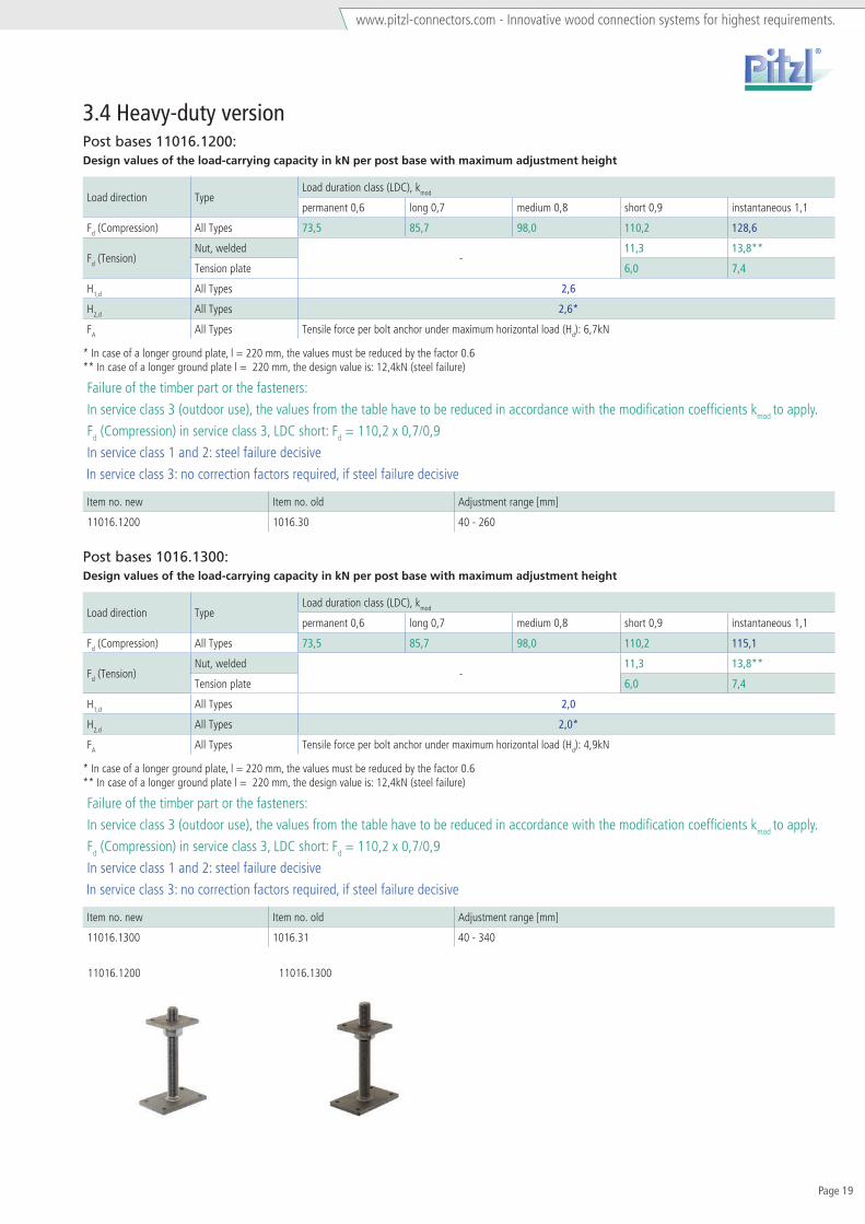
3.4 Heavy-duty versionPost bases 11016.1200:Design values of the load-carrying capacity in kN per post base with maximum adjustment height
Load direction TypeLoad duration class (LDC), kmod
permanent 0,6 long 0,7 medium 0,8 short 0,9 instantaneous 1,1
Fd (Compression) All Types 73,5 85,7 98,0 110,2 128,6
Fd (Tension)Nut, welded
-11,3 13,8**
Tension plate 6,0 7,4
H1,d All Types 2,6
H2,d All Types 2,6*
FA All Types Tensile force per bolt anchor under maximum horizontal load (Hd): 6,7kN
* In case of a longer ground plate, l = 220 mm, the values must be reduced by the factor 0.6 ** In case of a longer ground plate l = 220 mm, the design value is: 12,4kN (steel failure)
Failure of the timber part or the fasteners:
In service class 3 (outdoor use), the values from the table have to be reduced in accordance with the modification coefficients kmod to apply.
Fd (Compression) in service class 3, LDC short: Fd = 110,2 x 0,7/0,9
In service class 1 and 2: steel failure decisive
In service class 3: no correction factors required, if steel failure decisive
Item no. new Item no. old Adjustment range [mm]
11016.1200 1016.30 40 - 260
Post bases 1016.1300:Design values of the load-carrying capacity in kN per post base with maximum adjustment height
Load direction TypeLoad duration class (LDC), kmod
permanent 0,6 long 0,7 medium 0,8 short 0,9 instantaneous 1,1
Fd (Compression) All Types 73,5 85,7 98,0 110,2 115,1
Fd (Tension)Nut, welded
-11,3 13,8**
Tension plate 6,0 7,4
H1,d All Types 2,0
H2,d All Types 2,0*
FA All Types Tensile force per bolt anchor under maximum horizontal load (Hd): 4,9kN
* In case of a longer ground plate, l = 220 mm, the values must be reduced by the factor 0.6 ** In case of a longer ground plate l = 220 mm, the design value is: 12,4kN (steel failure)
Failure of the timber part or the fasteners:
In service class 3 (outdoor use), the values from the table have to be reduced in accordance with the modification coefficients kmod to apply.
Fd (Compression) in service class 3, LDC short: Fd = 110,2 x 0,7/0,9
In service class 1 and 2: steel failure decisive
In service class 3: no correction factors required, if steel failure decisive
Item no. new Item no. old Adjustment range [mm]
11016.1300 1016.31 40 - 340
11016.1200 11016.1300
For further information: www.pitzl-connectors.com. Individual consulting: +49 8703 9346-0Page 20
Post bases - Design Manual
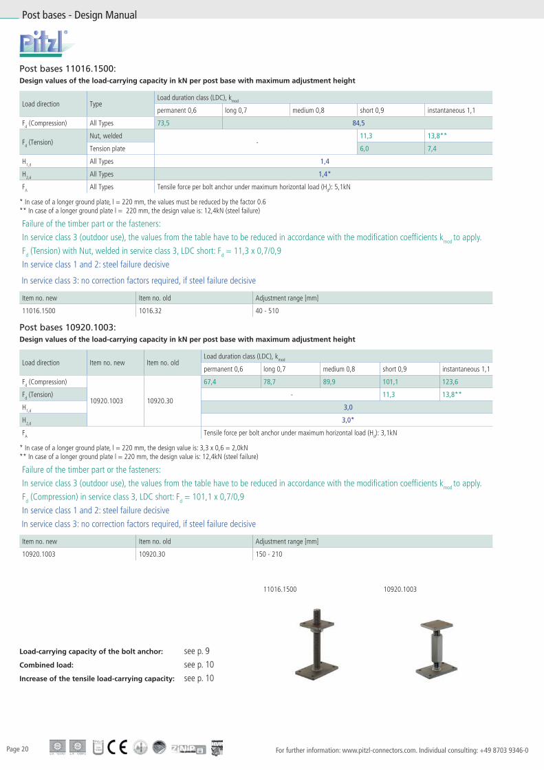
Post bases 11016.1500:Design values of the load-carrying capacity in kN per post base with maximum adjustment height
Load direction TypeLoad duration class (LDC), kmod
permanent 0,6 long 0,7 medium 0,8 short 0,9 instantaneous 1,1
Fd (Compression) All Types 73,5 84,5
Fd (Tension)Nut, welded
-11,3 13,8**
Tension plate 6,0 7,4
H1,d All Types 1,4
H2,d All Types 1,4*
FA All Types Tensile force per bolt anchor under maximum horizontal load (Hd): 5,1kN
* In case of a longer ground plate, l = 220 mm, the values must be reduced by the factor 0.6 ** In case of a longer ground plate l = 220 mm, the design value is: 12,4kN (steel failure)
Failure of the timber part or the fasteners:
In service class 3 (outdoor use), the values from the table have to be reduced in accordance with the modification coefficients kmod to apply.
Fd (Tension) with Nut, welded in service class 3, LDC short: Fd = 11,3 x 0,7/0,9
In service class 1 and 2: steel failure decisive
In service class 3: no correction factors required, if steel failure decisive
Item no. new Item no. old Adjustment range [mm]
11016.1500 1016.32 40 - 510
Post bases 10920.1003:Design values of the load-carrying capacity in kN per post base with maximum adjustment height
Load direction Item no. new Item no. oldLoad duration class (LDC), kmod
permanent 0,6 long 0,7 medium 0,8 short 0,9 instantaneous 1,1
Fd (Compression)
10920.1003 10920.30
67,4 78,7 89,9 101,1 123,6
Fd (Tension) - 11,3 13,8**
H1,d 3,0
H2,d 3,0*
FA Tensile force per bolt anchor under maximum horizontal load (Hd): 3,1kN
* In case of a longer ground plate, l = 220 mm, the design value is: 3,3 x 0,6 = 2,0kN ** In case of a longer ground plate l = 220 mm, the design value is: 12,4kN (steel failure)
Failure of the timber part or the fasteners:
In service class 3 (outdoor use), the values from the table have to be reduced in accordance with the modification coefficients kmod to apply.
Fd (Compression) in service class 3, LDC short: Fd = 101,1 x 0,7/0,9
In service class 1 and 2: steel failure decisive
In service class 3: no correction factors required, if steel failure decisive
Item no. new Item no. old Adjustment range [mm]
10920.1003 10920.30 150 - 210
10920.100311016.1500
Load-carrying capacity of the bolt anchor: see p. 9
Combined load: see p. 10
Increase of the tensile load-carrying capacity: see p. 10
Page 21
www.pitzl-connectors.com - Innovative wood connection systems for highest requirements.
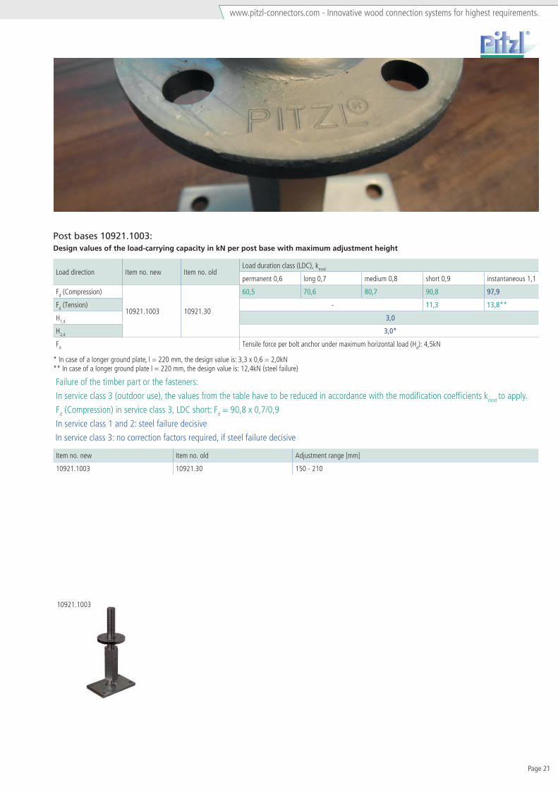
Post bases 10921.1003:Design values of the load-carrying capacity in kN per post base with maximum adjustment height
Load direction Item no. new Item no. oldLoad duration class (LDC), kmod
permanent 0,6 long 0,7 medium 0,8 short 0,9 instantaneous 1,1
Fd (Compression)
10921.1003 10921.30
60,5 70,6 80,7 90,8 97,9
Fd (Tension) - 11,3 13,8**
H1,d 3,0
H2,d 3,0*
FA Tensile force per bolt anchor under maximum horizontal load (Hd): 4,5kN
* In case of a longer ground plate, l = 220 mm, the design value is: 3,3 x 0,6 = 2,0kN ** In case of a longer ground plate l = 220 mm, the design value is: 12,4kN (steel failure)
Failure of the timber part or the fasteners:
In service class 3 (outdoor use), the values from the table have to be reduced in accordance with the modification coefficients kmod to apply.
Fd (Compression) in service class 3, LDC short: Fd = 90,8 x 0,7/0,9
In service class 1 and 2: steel failure decisive
In service class 3: no correction factors required, if steel failure decisive
Item no. new Item no. old Adjustment range [mm]
10921.1003 10921.30 150 - 210
10921.1003
For further information: www.pitzl-connectors.com. Individual consulting: +49 8703 9346-0Page 22
Post bases - Design Manual
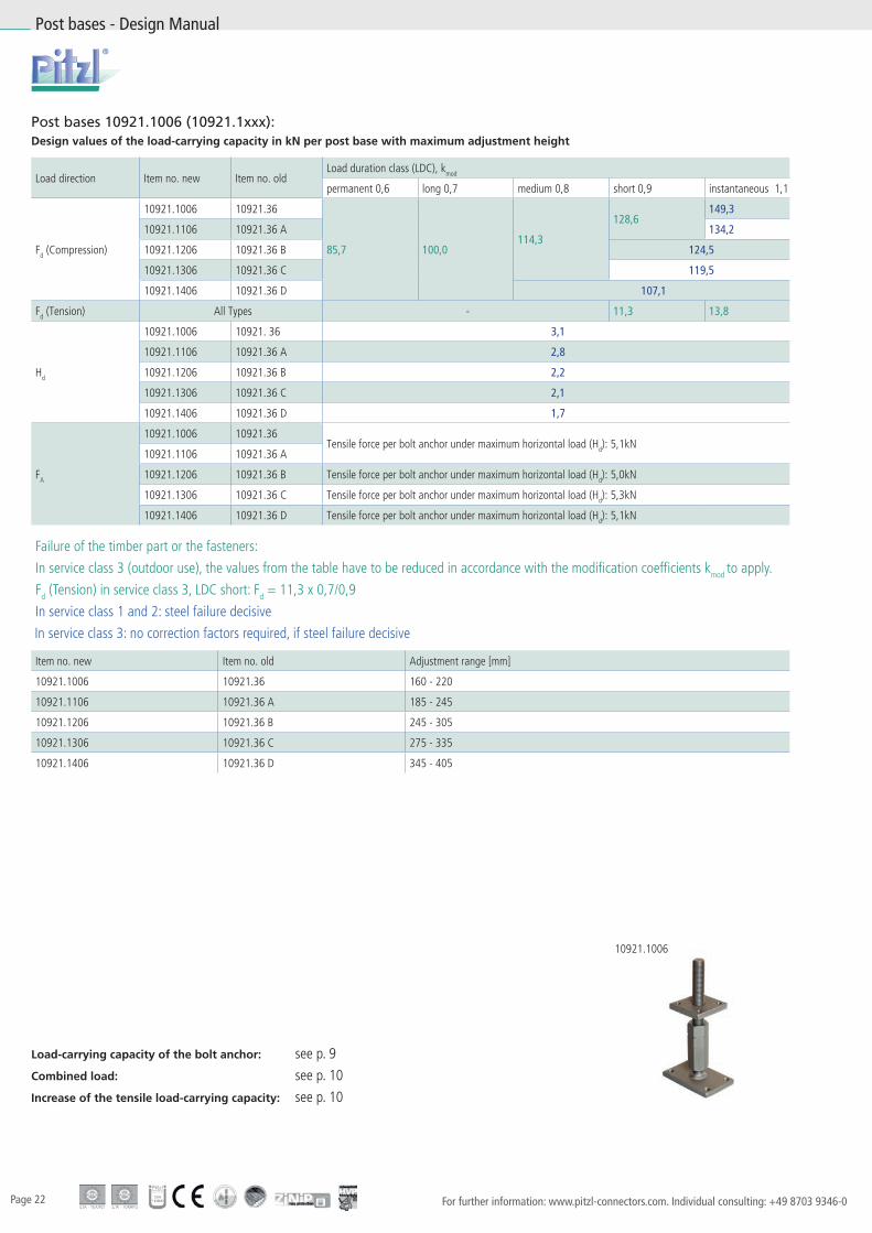
Post bases 10921.1006 (10921.1xxx):Design values of the load-carrying capacity in kN per post base with maximum adjustment height
Load direction Item no. new Item no. oldLoad duration class (LDC), kmod
permanent 0,6 long 0,7 medium 0,8 short 0,9 instantaneous 1,1
Fd (Compression)
10921.1006 10921.36
85,7 100,0114,3
128,6149,3
10921.1106 10921.36 A 134,2
10921.1206 10921.36 B 124,5
10921.1306 10921.36 C 119,5
10921.1406 10921.36 D 107,1
Fd (Tension) All Types - 11,3 13,8
Hd
10921.1006 10921. 36 3,1
10921.1106 10921.36 A 2,8
10921.1206 10921.36 B 2,2
10921.1306 10921.36 C 2,1
10921.1406 10921.36 D 1,7
FA
10921.1006 10921.36Tensile force per bolt anchor under maximum horizontal load (Hd): 5,1kN
10921.1106 10921.36 A
10921.1206 10921.36 B Tensile force per bolt anchor under maximum horizontal load (Hd): 5,0kN
10921.1306 10921.36 C Tensile force per bolt anchor under maximum horizontal load (Hd): 5,3kN
10921.1406 10921.36 D Tensile force per bolt anchor under maximum horizontal load (Hd): 5,1kN
Failure of the timber part or the fasteners:
In service class 3 (outdoor use), the values from the table have to be reduced in accordance with the modification coefficients kmod to apply.
Fd (Tension) in service class 3, LDC short: Fd = 11,3 x 0,7/0,9
In service class 1 and 2: steel failure decisive
In service class 3: no correction factors required, if steel failure decisive
Item no. new Item no. old Adjustment range [mm]
10921.1006 10921.36 160 - 220
10921.1106 10921.36 A 185 - 245
10921.1206 10921.36 B 245 - 305
10921.1306 10921.36 C 275 - 335
10921.1406 10921.36 D 345 - 405
10921.1006
Load-carrying capacity of the bolt anchor: see p. 9
Combined load: see p. 10
Increase of the tensile load-carrying capacity: see p. 10
Page 23
www.pitzl-connectors.com - Innovative wood connection systems for highest requirements.
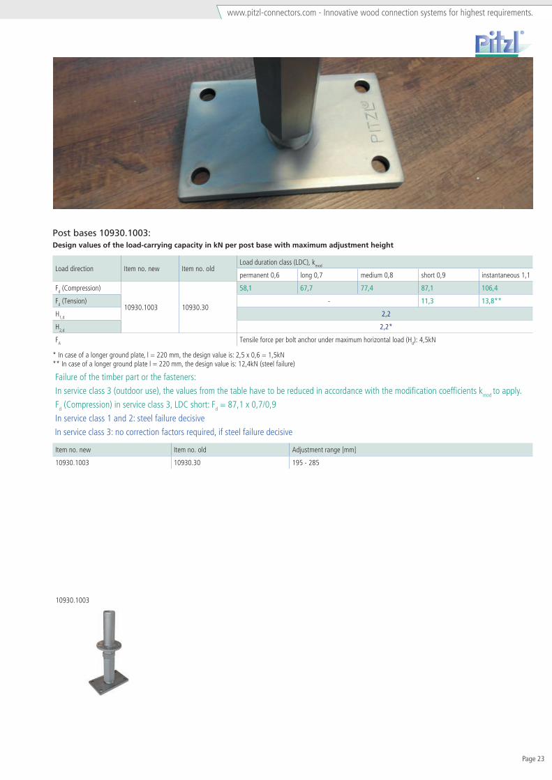
Post bases 10930.1003:Design values of the load-carrying capacity in kN per post base with maximum adjustment height
Load direction Item no. new Item no. oldLoad duration class (LDC), kmod
permanent 0,6 long 0,7 medium 0,8 short 0,9 instantaneous 1,1
Fd (Compression)
10930.1003 10930.30
58,1 67,7 77,4 87,1 106,4
Fd (Tension) - 11,3 13,8**
H1,d 2,2
H2,d 2,2*
FA Tensile force per bolt anchor under maximum horizontal load (Hd): 4,5kN
* In case of a longer ground plate, l = 220 mm, the design value is: 2,5 x 0,6 = 1,5kN ** In case of a longer ground plate l = 220 mm, the design value is: 12,4kN (steel failure)
Failure of the timber part or the fasteners:
In service class 3 (outdoor use), the values from the table have to be reduced in accordance with the modification coefficients kmod to apply.
Fd (Compression) in service class 3, LDC short: Fd = 87,1 x 0,7/0,9
In service class 1 and 2: steel failure decisive
In service class 3: no correction factors required, if steel failure decisive
Item no. new Item no. old Adjustment range [mm]
10930.1003 10930.30 195 - 285
10930.1003
For further information: www.pitzl-connectors.com. Individual consulting: +49 8703 9346-0Page 24
Post bases - Design Manual
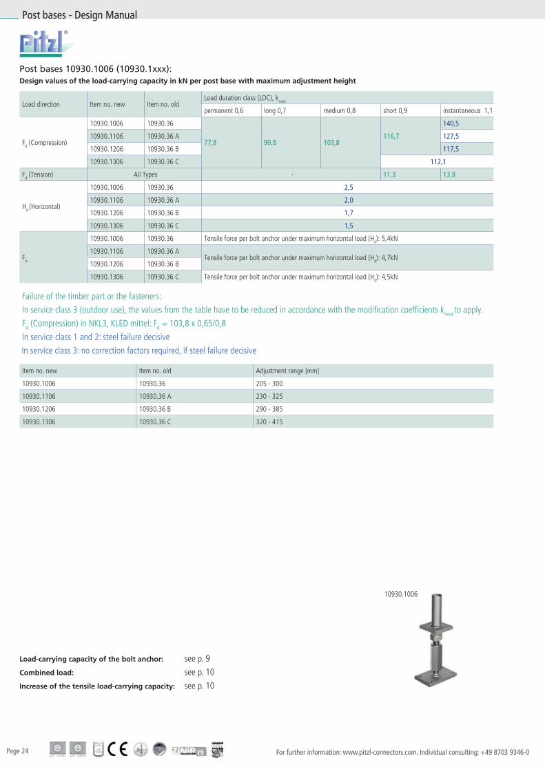
Post bases 10930.1006 (10930.1xxx):Design values of the load-carrying capacity in kN per post base with maximum adjustment height
Load direction Item no. new Item no. oldLoad duration class (LDC), kmod
permanent 0,6 long 0,7 medium 0,8 short 0,9 instantaneous 1,1
Fd (Compression)
10930.1006 10930.36
77,8 90,8 103,8116,7
140,5
10930.1106 10930.36 A 127,5
10930.1206 10930.36 B 117,5
10930.1306 10930.36 C 112,1
Fd (Tension) All Types - 11,3 13,8
Hd (Horizontal)
10930.1006 10930.36 2,5
10930.1106 10930.36 A 2,0
10930.1206 10930.36 B 1,7
10930.1306 10930.36 C 1,5
FA
10930.1006 10930.36 Tensile force per bolt anchor under maximum horizontal load (Hd): 5,4kN
10930.1106 10930.36 ATensile force per bolt anchor under maximum horizontal load (Hd): 4,7kN
10930.1206 10930.36 B
10930.1306 10930.36 C Tensile force per bolt anchor under maximum horizontal load (Hd): 4,5kN
Failure of the timber part or the fasteners:
In service class 3 (outdoor use), the values from the table have to be reduced in accordance with the modification coefficients kmod to apply.
Fd (Compression) in NKL3, KLED mittel: Fd = 103,8 x 0,65/0,8
In service class 1 and 2: steel failure decisive
In service class 3: no correction factors required, if steel failure decisive
Item no. new Item no. old Adjustment range [mm]
10930.1006 10930.36 205 - 300
10930.1106 10930.36 A 230 - 325
10930.1206 10930.36 B 290 - 385
10930.1306 10930.36 C 320 - 415
10930.1006
Load-carrying capacity of the bolt anchor: see p. 9
Combined load: see p. 10
Increase of the tensile load-carrying capacity: see p. 10
Page 25
www.pitzl-connectors.com - Innovative wood connection systems for highest requirements.
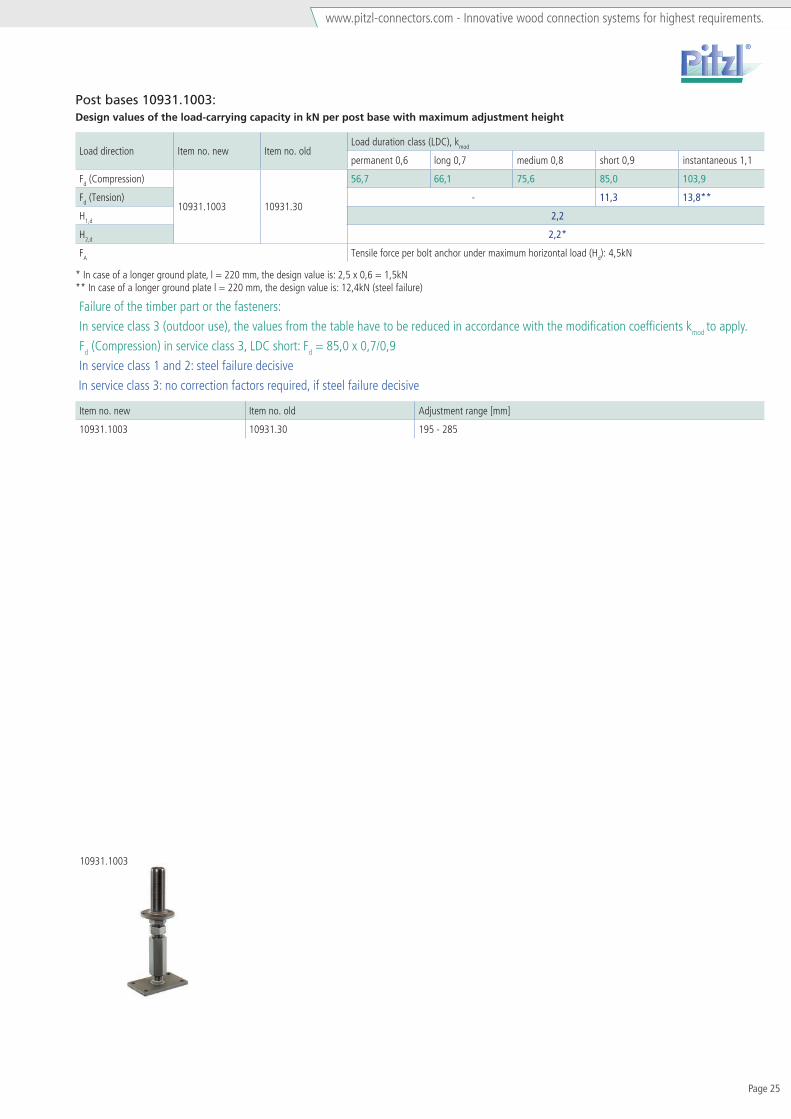
Post bases 10931.1003:Design values of the load-carrying capacity in kN per post base with maximum adjustment height
Load direction Item no. new Item no. oldLoad duration class (LDC), kmod
permanent 0,6 long 0,7 medium 0,8 short 0,9 instantaneous 1,1
Fd (Compression)
10931.1003 10931.30
56,7 66,1 75,6 85,0 103,9
Fd (Tension) - 11,3 13,8**
H1,d 2,2
H2,d 2,2*
FA Tensile force per bolt anchor under maximum horizontal load (Hd): 4,5kN
* In case of a longer ground plate, l = 220 mm, the design value is: 2,5 x 0,6 = 1,5kN ** In case of a longer ground plate l = 220 mm, the design value is: 12,4kN (steel failure)
Failure of the timber part or the fasteners:
In service class 3 (outdoor use), the values from the table have to be reduced in accordance with the modification coefficients kmod to apply.
Fd (Compression) in service class 3, LDC short: Fd = 85,0 x 0,7/0,9
In service class 1 and 2: steel failure decisive
In service class 3: no correction factors required, if steel failure decisive
Item no. new Item no. old Adjustment range [mm]
10931.1003 10931.30 195 - 285
10931.1003
For further information: www.pitzl-connectors.com. Individual consulting: +49 8703 9346-0Page 26
Post bases - Design Manual
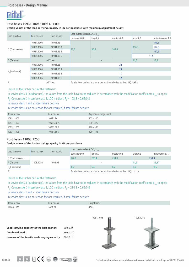
Post bases 10931.1006 (10931.1xxx):Design values of the load-carrying capacity in kN per post base with maximum adjustment height
Load direction Item no. new Item no. oldLoad duration class (LDC), kmod
permanent 0,6 long 0,7 medium 0,8 short 0,9 instantaneous 1,1
Fd (Compression)
10931.1006 10931.36
77,8 90,8 103,8116,7
140,5
10931.1106 10931.36 A 127,5
10931.1206 10931.36 B 117,5
10931.1306 10931.36 C 112,1
Fd (Tension) All Types - 11,3 13,8
Hd (Horizontal)
10931.1006 10931.36 2,5
10931.1106 10931.36 A 2,0
10931.1206 10931.36 B 1,7
10931.1306 10931.36 C 1,5
FA All Types Tensile force per bolt anchor under maximum horizontal load (Hd): 5,6kN
Failure of the timber part or the fasteners:
In service class 3 (outdoor use), the values from the table have to be reduced in accordance with the modification coefficients kmod to apply.
Fd (Compression) in service class 3, LDC medium: Fd = 103,8 x 0,65/0,8
In service class 1 and 2: steel failure decisive
In service class 3: no correction factors required, if steel failure decisive
Item no. new Item no. old Adjustment range [mm]
10931.1006 10931.36 205 - 300
10931.1106 10931.36 A 230 - 325
10931.1206 10931.36 B 290 - 385
10931.1306 10931.36 C 320 - 415
Post bases 11008.1250:Design values of the load-carrying capacity in kN per post base
Load direction Item no. new Item no. oldLoad duration class (LDC), kmod
permanent 0,6 long 0,7 medium 0,8 short 0,9 instantaneous 1,1
Fd (Compression)
11008.1250 1008.08
176,1 205,4 234,8 253,9
Fd (Tension) - 11,3 13,8**
Hd (Horizontal) 4,6 5,4 6,2 6,9 8,5
FA Tensile force per bolt anchor under maximum horizontal load (Hd): 11,1kN
Failure of the timber part or the fasteners:
In service class 3 (outdoor use), the values from the table have to be reduced in accordance with the modification coefficients kmod to apply.
Fd (Compression) in service class 3, LDC medium: Fd = 234,8 x 0,65/0,8
In service class 1 and 2: steel failure decisive
In service class 3: no correction factors required, if steel failure decisive
Item no. new Item no. old Height [mm]
11008.1250 1008.08 250
11008.125010931.1006
Load-carrying capacity of the bolt anchor: see p. 9
Combined load: see p. 10
Increase of the tensile load-carrying capacity: see p. 10
Page 27
www.pitzl-connectors.com - Innovative wood connection systems for highest requirements.
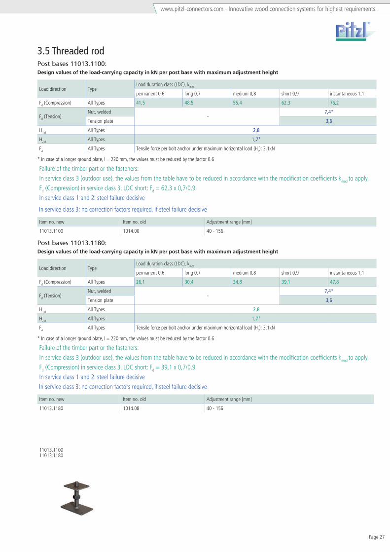
3.5 Threaded rodPost bases 11013.1100:Design values of the load-carrying capacity in kN per post base with maximum adjustment height
Load direction TypeLoad duration class (LDC), kmod
permanent 0,6 long 0,7 medium 0,8 short 0,9 instantaneous 1,1
Fd (Compression) All Types 41,5 48,5 55,4 62,3 76,2
Fd (Tension)Nut, welded
-7,4*
Tension plate 3,6
H1,d All Types 2,8
H2,d All Types 1,7*
FA All Types Tensile force per bolt anchor under maximum horizontal load (Hd): 3,1kN
* In case of a longer ground plate, l = 220 mm, the values must be reduced by the factor 0.6
Failure of the timber part or the fasteners:
In service class 3 (outdoor use), the values from the table have to be reduced in accordance with the modification coefficients kmod to apply.
Fd (Compression) in service class 3, LDC short: Fd = 62,3 x 0,7/0,9
In service class 1 and 2: steel failure decisive
In service class 3: no correction factors required, if steel failure decisive
Item no. new Item no. old Adjustment range [mm]
11013.1100 1014.00 40 - 156
Post bases 11013.1180:Design values of the load-carrying capacity in kN per post base with maximum adjustment height
Load direction TypeLoad duration class (LDC), kmod
permanent 0,6 long 0,7 medium 0,8 short 0,9 instantaneous 1,1
Fd (Compression) All Types 26,1 30,4 34,8 39,1 47,8
Fd (Tension)Nut, welded
-7,4*
Tension plate 3,6
H1,d All Types 2,8
H2,d All Types 1,7*
FA All Types Tensile force per bolt anchor under maximum horizontal load (Hd): 3,1kN
* In case of a longer ground plate, l = 220 mm, the values must be reduced by the factor 0.6
Failure of the timber part or the fasteners:
In service class 3 (outdoor use), the values from the table have to be reduced in accordance with the modification coefficients kmod to apply.
Fd (Compression) in service class 3, LDC short: Fd = 39,1 x 0,7/0,9
In service class 1 and 2: steel failure decisive
In service class 3: no correction factors required, if steel failure decisive
Item no. new Item no. old Adjustment range [mm]
11013.1180 1014.08 40 - 156
11013.110011013.1180
For further information: www.pitzl-connectors.com. Individual consulting: +49 8703 9346-0Page 28
Post bases - Design Manual
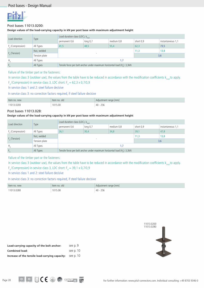
Post bases 11013.0200:Design values of the load-carrying capacity in kN per post base with maximum adjustment height
Load direction TypeLoad duration class (LDC), kmod
permanent 0,6 long 0,7 medium 0,8 short 0,9 instantaneous 1,1
Fd (Compression) All Types 41,5 48,5 55,4 62,3 73,5
Fd (Tension)Nut, welded
-11,3 13,8
Tension plate 3,6
Hd All Types 1,7
FA All Types Tensile force per bolt anchor under maximum horizontal load (Hd): 3,3kN
Failure of the timber part or the fasteners:
In service class 3 (outdoor use), the values from the table have to be reduced in accordance with the modification coefficients kmod to apply.
Fd (Compression) in service class 3, LDC short: Fd = 62,3 x 0,7/0,9
In service class 1 and 2: steel failure decisive
In service class 3: no correction factors required, if steel failure decisive
Item no. new Item no. old Adjustment range [mm]
11013.0200 1015.00 40 - 256
Post bases 11013.028:Design values of the load-carrying capacity in kN per post base with maximum adjustment height
Load direction TypeLoad duration class (LDC), kmod
permanent 0,6 long 0,7 medium 0,8 short 0,9 instantaneous 1,1
Fd (Compression) All Types 26,1 30,4 34,8 39,1 47,8
Fd (Tension)Nut, welded
-11,3 13,8
Tension plate 3,6
Hd All Types 1,7
FA All Types Tensile force per bolt anchor under maximum horizontal load (Hd): 3,3kN
Failure of the timber part or the fasteners:
In service class 3 (outdoor use), the values from the table have to be reduced in accordance with the modification coefficients kmod to apply.
Fd (Compression) in service class 3, LDC short: Fd = 39,1 x 0,7/0,9
In service class 1 and 2: steel failure decisive
In service class 3: no correction factors required, if steel failure decisive
Item no. new Item no. old Adjustment range [mm]
11013.0280 1015.08 40 - 256
11013.028011013.0200
Load-carrying capacity of the bolt anchor: see p. 9
Combined load: see p. 10
Increase of the tensile load-carrying capacity: see p. 10
Page 29
www.pitzl-connectors.com - Innovative wood connection systems for highest requirements.
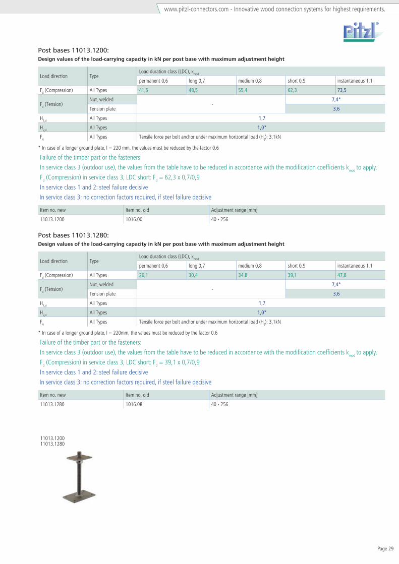
Post bases 11013.1200:Design values of the load-carrying capacity in kN per post base with maximum adjustment height
Load direction TypeLoad duration class (LDC), kmod
permanent 0,6 long 0,7 medium 0,8 short 0,9 instantaneous 1,1
Fd (Compression) All Types 41,5 48,5 55,4 62,3 73,5
Fd (Tension)Nut, welded
-7,4*
Tension plate 3,6
H1,d All Types 1,7
H2,d All Types 1,0*
FA All Types Tensile force per bolt anchor under maximum horizontal load (Hd): 3,1kN
* In case of a longer ground plate, l = 220 mm, the values must be reduced by the factor 0.6
Failure of the timber part or the fasteners:
In service class 3 (outdoor use), the values from the table have to be reduced in accordance with the modification coefficients kmod to apply.
Fd (Compression) in service class 3, LDC short: Fd = 62,3 x 0,7/0,9
In service class 1 and 2: steel failure decisive
In service class 3: no correction factors required, if steel failure decisive
Item no. new Item no. old Adjustment range [mm]
11013.1200 1016.00 40 - 256
Post bases 11013.1280:Design values of the load-carrying capacity in kN per post base with maximum adjustment height
Load direction TypeLoad duration class (LDC), kmod
permanent 0,6 long 0,7 medium 0,8 short 0,9 instantaneous 1,1
Fd (Compression) All Types 26,1 30,4 34,8 39,1 47,8
Fd (Tension)Nut, welded
-7,4*
Tension plate 3,6
H1,d All Types 1,7
H2,d All Types 1,0*
FA All Types Tensile force per bolt anchor under maximum horizontal load (Hd): 3,1kN
* In case of a longer ground plate, l = 220mm, the values must be reduced by the factor 0.6
Failure of the timber part or the fasteners:
In service class 3 (outdoor use), the values from the table have to be reduced in accordance with the modification coefficients kmod to apply.
Fd (Compression) in service class 3, LDC short: Fd = 39,1 x 0,7/0,9
In service class 1 and 2: steel failure decisive
In service class 3: no correction factors required, if steel failure decisive
Item no. new Item no. old Adjustment range [mm]
11013.1280 1016.08 40 - 256
11013.120011013.1280
For further information: www.pitzl-connectors.com. Individual consulting: +49 8703 9346-0Page 30
Post bases - Design Manual
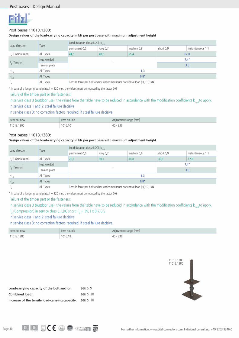
Post bases 11013.1300:Design values of the load-carrying capacity in kN per post base with maximum adjustment height
Load direction TypeLoad duration class (LDC), kmod
permanent 0,6 long 0,7 medium 0,8 short 0,9 instantaneous 1,1
Fd (Compression) All Types 41,5 48,5 55,4 62,0
Fd (Tension)Nut, welded
-7,4*
Tension plate 3,6
H1,d All Types 1,3
H2,d All Types 0,8*
FA All Types Tensile force per bolt anchor under maximum horizontal load (Hd): 3,1kN
* In case of a longer ground plate, l = 220 mm, the values must be reduced by the factor 0.6
Failure of the timber part or the fasteners:
In service class 3 (outdoor use), the values from the table have to be reduced in accordance with the modification coefficients kmod to apply.
In service class 1 and 2: steel failure decisive
In service class 3: no correction factors required, if steel failure decisive
Item no. new Item no. old Adjustment range [mm]
11013.1300 1016.10 40 - 336
Post bases 11013.1380:Design values of the load-carrying capacity in kN per post base with maximum adjustment height
Load direction TypeLoad duration class (LDC), kmod
permanent 0,6 long 0,7 medium 0,8 short 0,9 instantaneous 1,1
Fd (Compression) All Types 26,1 30,4 34,8 39,1 47,8
Fd (Tension)Nut, welded
-7,4*
Tension plate 3,6
H1,d All Types 1,3
H2,d All Types 0,8*
FA All Types Tensile force per bolt anchor under maximum horizontal load (Hd): 3,1kN
* In case of a longer ground plate, l = 220 mm, the values must be reduced by the factor 0.6
Failure of the timber part or the fasteners:
In service class 3 (outdoor use), the values from the table have to be reduced in accordance with the modification coefficients kmod to apply.
Fd (Compression) in service class 3, LDC short: Fd = 39,1 x 0,7/0,9
In service class 1 and 2: steel failure decisive
In service class 3: no correction factors required, if steel failure decisive
Item no. new Item no. old Adjustment range [mm]
11013.1380 1016.18 40 - 336
11013.138011013.1300
Load-carrying capacity of the bolt anchor: see p. 9
Combined load: see p. 10
Increase of the tensile load-carrying capacity: see p. 10
Page 31
www.pitzl-connectors.com - Innovative wood connection systems for highest requirements.
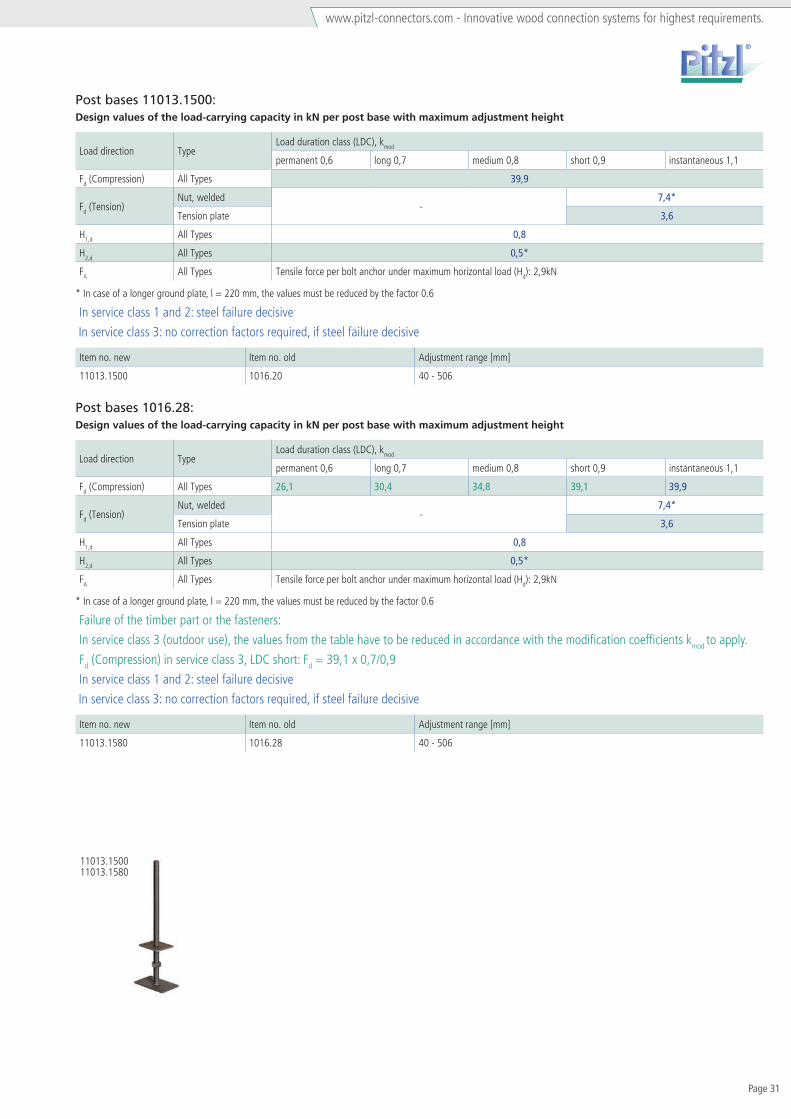
Post bases 11013.1500:Design values of the load-carrying capacity in kN per post base with maximum adjustment height
Load direction TypeLoad duration class (LDC), kmod
permanent 0,6 long 0,7 medium 0,8 short 0,9 instantaneous 1,1
Fd (Compression) All Types 39,9
Fd (Tension)Nut, welded
-7,4*
Tension plate 3,6
H1,d All Types 0,8
H2,d All Types 0,5*
FA All Types Tensile force per bolt anchor under maximum horizontal load (Hd): 2,9kN
* In case of a longer ground plate, l = 220 mm, the values must be reduced by the factor 0.6
In service class 1 and 2: steel failure decisive
In service class 3: no correction factors required, if steel failure decisive
Item no. new Item no. old Adjustment range [mm]
11013.1500 1016.20 40 - 506
Post bases 1016.28:Design values of the load-carrying capacity in kN per post base with maximum adjustment height
Load direction TypeLoad duration class (LDC), kmod
permanent 0,6 long 0,7 medium 0,8 short 0,9 instantaneous 1,1
Fd (Compression) All Types 26,1 30,4 34,8 39,1 39,9
Fd (Tension)Nut, welded
-7,4*
Tension plate 3,6
H1,d All Types 0,8
H2,d All Types 0,5*
FA All Types Tensile force per bolt anchor under maximum horizontal load (Hd): 2,9kN
* In case of a longer ground plate, l = 220 mm, the values must be reduced by the factor 0.6
Failure of the timber part or the fasteners:
In service class 3 (outdoor use), the values from the table have to be reduced in accordance with the modification coefficients kmod to apply.
Fd (Compression) in service class 3, LDC short: Fd = 39,1 x 0,7/0,9
In service class 1 and 2: steel failure decisive
In service class 3: no correction factors required, if steel failure decisive
Item no. new Item no. old Adjustment range [mm]
11013.1580 1016.28 40 - 506
11013.150011013.1580
For further information: www.pitzl-connectors.com. Individual consulting: +49 8703 9346-0Page 32
Post bases - Design Manual
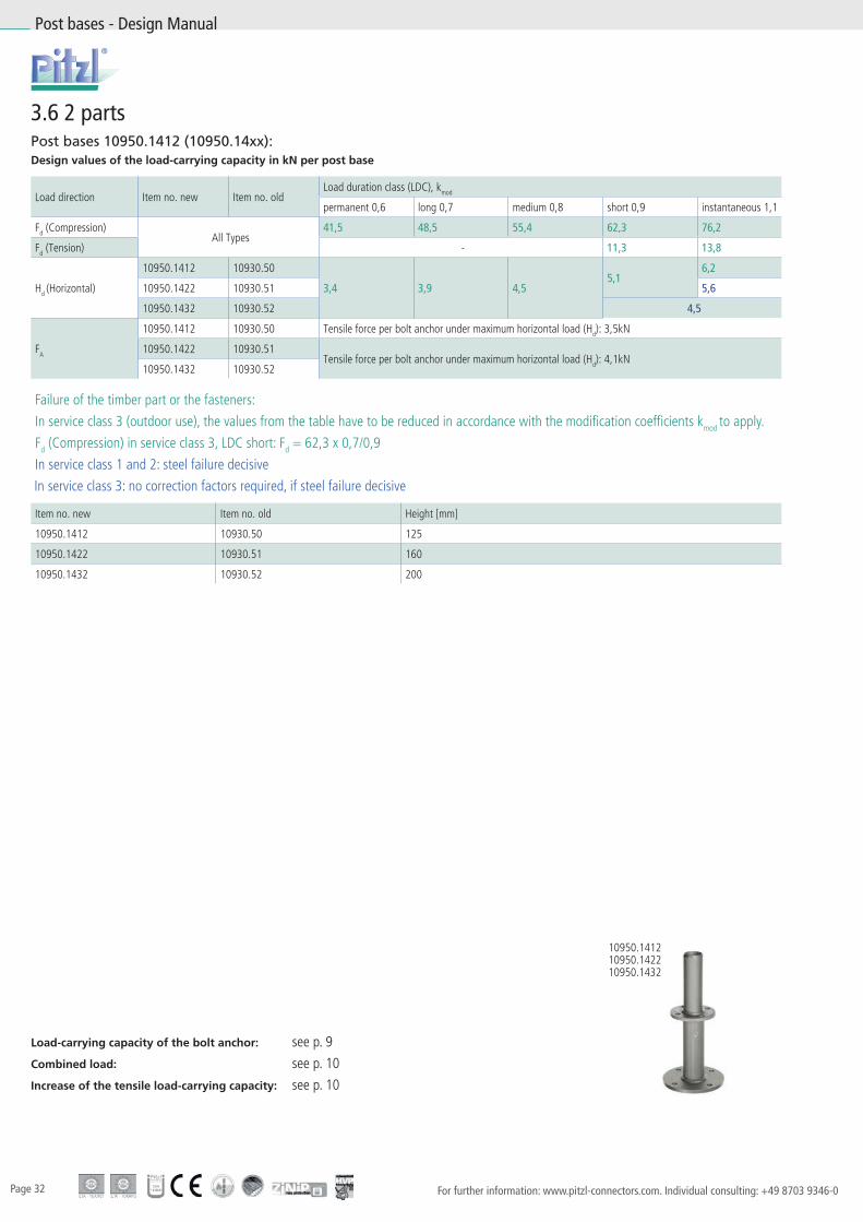
3.6 2 partsPost bases 10950.1412 (10950.14xx):Design values of the load-carrying capacity in kN per post base
Load direction Item no. new Item no. oldLoad duration class (LDC), kmod
permanent 0,6 long 0,7 medium 0,8 short 0,9 instantaneous 1,1
Fd (Compression)All Types
41,5 48,5 55,4 62,3 76,2
Fd (Tension) - 11,3 13,8
Hd (Horizontal)
10950.1412 10930.50
3,4 3,9 4,55,1
6,2
10950.1422 10930.51 5,6
10950.1432 10930.52 4,5
FA
10950.1412 10930.50 Tensile force per bolt anchor under maximum horizontal load (Hd): 3,5kN
10950.1422 10930.51Tensile force per bolt anchor under maximum horizontal load (Hd): 4,1kN
10950.1432 10930.52
Failure of the timber part or the fasteners:
In service class 3 (outdoor use), the values from the table have to be reduced in accordance with the modification coefficients kmod to apply.
Fd (Compression) in service class 3, LDC short: Fd = 62,3 x 0,7/0,9
In service class 1 and 2: steel failure decisive
In service class 3: no correction factors required, if steel failure decisive
Item no. new Item no. old Height [mm]
10950.1412 10930.50 125
10950.1422 10930.51 160
10950.1432 10930.52 200
10950.141210950.142210950.1432
Load-carrying capacity of the bolt anchor: see p. 9
Combined load: see p. 10
Increase of the tensile load-carrying capacity: see p. 10
Page 33
www.pitzl-connectors.com - Innovative wood connection systems for highest requirements.
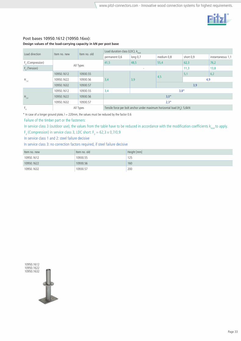
Post bases 10950.1612 (10950.16xx):Design values of the load-carrying capacity in kN per post base
Load direction Item no. new Item no. oldLoad duration class (LDC), kmod
permanent 0,6 long 0,7 medium 0,8 short 0,9 instantaneous 1,1
Fd (Compression)All Types
41,5 48,5 55,4 62,3 76,2
Fd (Tension) - 11,3 13,8
H1,d
10950.1612 10930.55
3,4 3,94,5
5,1 6,2
10950.1622 10930.56 4,9
10950.1632 10930.57 3,9
H2,d
10950.1612 10930.55 3,4 3,8*
10950.1622 10930.56 3,0*
10950.1632 10930.57 2,3*
FA All Types Tensile force per bolt anchor under maximum horizontal load (Hd): 5,6kN
* In case of a longer ground plate, l = 220mm, the values must be reduced by the factor 0.6
Failure of the timber part or the fasteners:
In service class 3 (outdoor use), the values from the table have to be reduced in accordance with the modification coefficients kmod to apply.
Fd (Compression) in service class 3, LDC short: Fd = 62,3 x 0,7/0,9
In service class 1 and 2: steel failure decisive
In service class 3: no correction factors required, if steel failure decisive
Item no. new Item no. old Height [mm]
10950.1612 10930.55 125
10950.1622 10930.56 160
10950.1632 10930.57 200
10950.161210950.162210950.1632
For further information: www.pitzl-connectors.com. Individual consulting: +49 8703 9346-0Page 34
Post bases - Design Manual
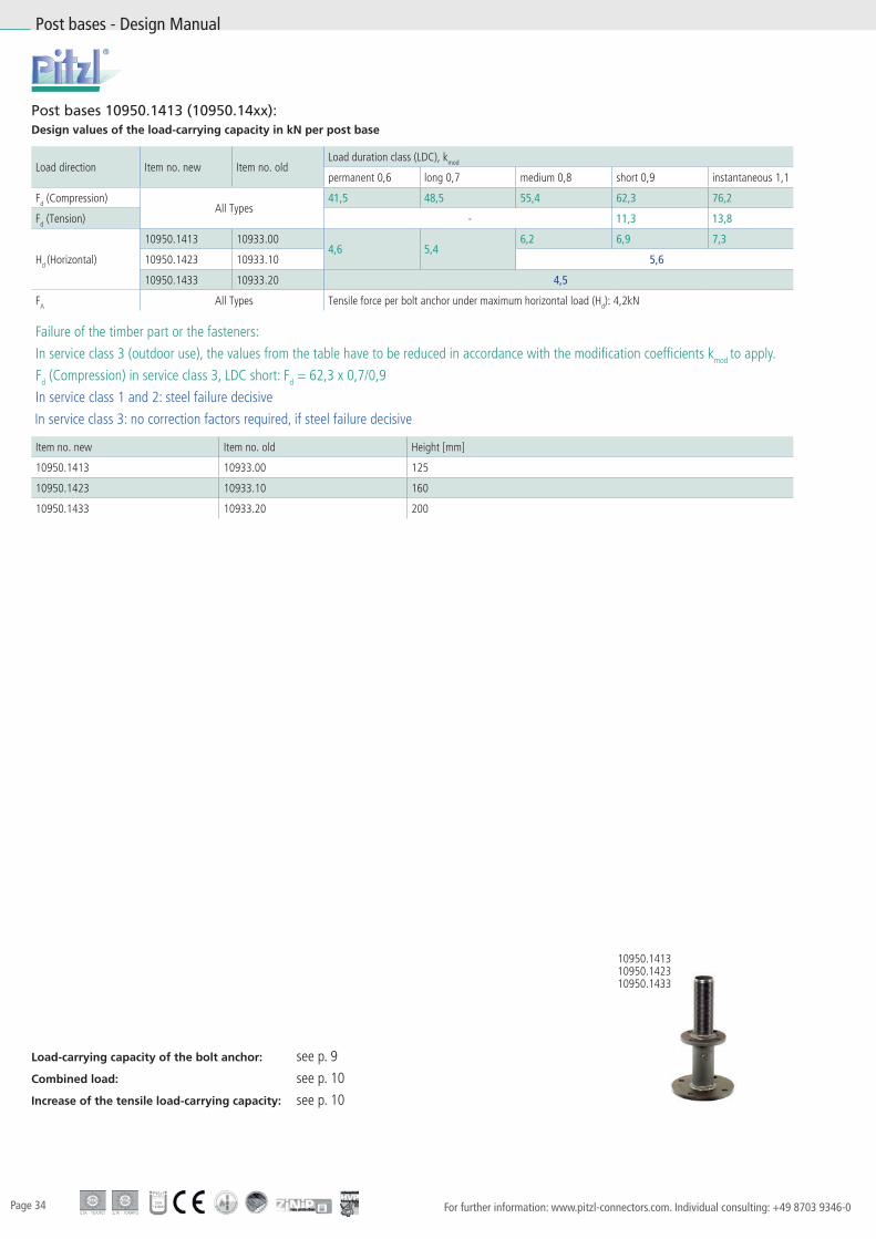
Post bases 10950.1413 (10950.14xx):Design values of the load-carrying capacity in kN per post base
Load direction Item no. new Item no. oldLoad duration class (LDC), kmod
permanent 0,6 long 0,7 medium 0,8 short 0,9 instantaneous 1,1
Fd (Compression)All Types
41,5 48,5 55,4 62,3 76,2
Fd (Tension) - 11,3 13,8
Hd (Horizontal)
10950.1413 10933.004,6 5,4
6,2 6,9 7,3
10950.1423 10933.10 5,6
10950.1433 10933.20 4,5
FA All Types Tensile force per bolt anchor under maximum horizontal load (Hd): 4,2kN
Failure of the timber part or the fasteners:
In service class 3 (outdoor use), the values from the table have to be reduced in accordance with the modification coefficients kmod to apply.
Fd (Compression) in service class 3, LDC short: Fd = 62,3 x 0,7/0,9
In service class 1 and 2: steel failure decisive
In service class 3: no correction factors required, if steel failure decisive
Item no. new Item no. old Height [mm]
10950.1413 10933.00 125
10950.1423 10933.10 160
10950.1433 10933.20 200
10950.141310950.142310950.1433
Load-carrying capacity of the bolt anchor: see p. 9
Combined load: see p. 10
Increase of the tensile load-carrying capacity: see p. 10
Page 35
www.pitzl-connectors.com - Innovative wood connection systems for highest requirements.
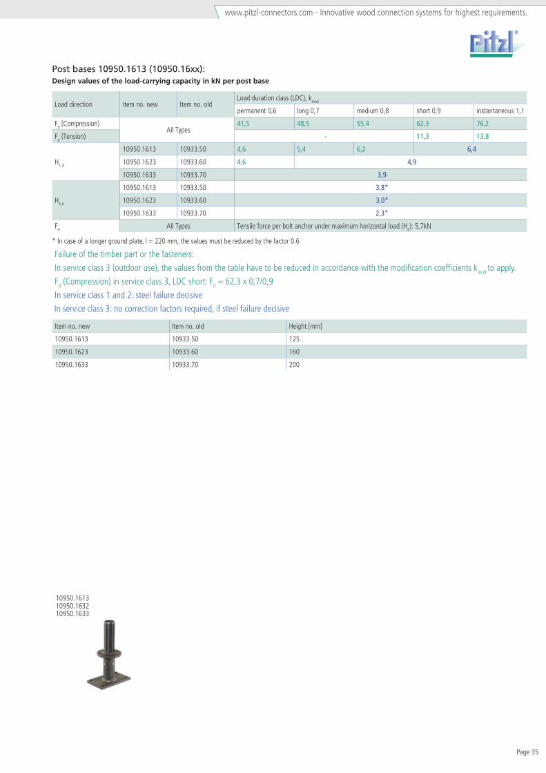
Post bases 10950.1613 (10950.16xx):Design values of the load-carrying capacity in kN per post base
Load direction Item no. new Item no. oldLoad duration class (LDC), kmod
permanent 0,6 long 0,7 medium 0,8 short 0,9 instantaneous 1,1
Fd (Compression)All Types
41,5 48,5 55,4 62,3 76,2
Fd (Tension) - 11,3 13,8
H1,d
10950.1613 10933.50 4,6 5,4 6,2 6,4
10950.1623 10933.60 4,6 4,9
10950.1633 10933.70 3,9
H2,d
10950.1613 10933.50 3,8*
10950.1623 10933.60 3,0*
10950.1633 10933.70 2,3*
FA All Types Tensile force per bolt anchor under maximum horizontal load (Hd): 5,7kN
* In case of a longer ground plate, l = 220 mm, the values must be reduced by the factor 0.6
Failure of the timber part or the fasteners:
In service class 3 (outdoor use), the values from the table have to be reduced in accordance with the modification coefficients kmod to apply.
Fd (Compression) in service class 3, LDC short: Fd = 62,3 x 0,7/0,9
In service class 1 and 2: steel failure decisive
In service class 3: no correction factors required, if steel failure decisive
Item no. new Item no. old Height [mm]
10950.1613 10933.50 125
10950.1623 10933.60 160
10950.1633 10933.70 200
10950.161310950.163210950.1633
For further information: www.pitzl-connectors.com. Individual consulting: +49 8703 9346-0Page 36
Post bases - Design Manual
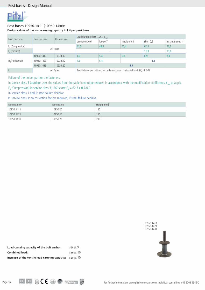
Post bases 10950.1411 (10950.14xx):Design values of the load-carrying capacity in kN per post base
Load direction Item no. new Item no. oldLoad duration class (LDC), kmod
permanent 0,6 long 0,7 medium 0,8 short 0,9 instantaneous 1,1
Fd (Compression)All Types
41,5 48,5 55,4 62,3 76,2
Fd (Tension) - 11,3 13,8
Hd (Horizontal)
10950.1413 10933.00 4,6 5,4 6,2 6,9 7,3
10950.1423 10933.10 4,6 5,4 5,6
10950.1433 10933.20 4,5
FA All Types Tensile force per bolt anchor under maximum horizontal load (Hd): 4,2kN
Failure of the timber part or the fasteners:
In service class 3 (outdoor use), the values from the table have to be reduced in accordance with the modification coefficients kmod to apply.
Fd (Compression) in service class 3, LDC short: Fd = 62.3 x 0,7/0,9
In service class 1 and 2: steel failure decisive
In service class 3: no correction factors required, if steel failure decisive
Item no. new Item no. old Height [mm]
10950.1411 10950.00 125
10950.1421 10950.10 160
10950.1431 10950.20 200
10950.141110950.142110950.1431
Load-carrying capacity of the bolt anchor: see p. 9
Combined load: see p. 10
Increase of the tensile load-carrying capacity: see p. 10
Page 37
www.pitzl-connectors.com - Innovative wood connection systems for highest requirements.
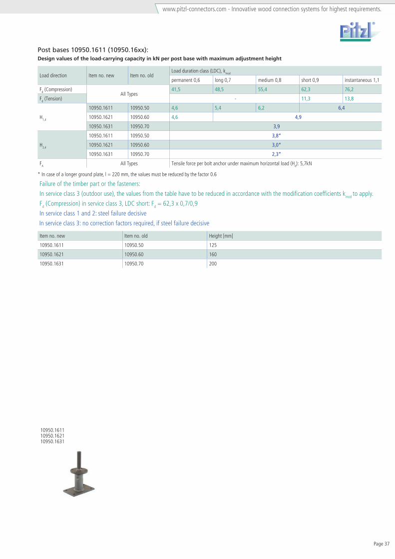
Post bases 10950.1611 (10950.16xx):Design values of the load-carrying capacity in kN per post base with maximum adjustment height
Load direction Item no. new Item no. oldLoad duration class (LDC), kmod
permanent 0,6 long 0,7 medium 0,8 short 0,9 instantaneous 1,1
Fd (Compression)All Types
41,5 48,5 55,4 62,3 76,2
Fd (Tension) - 11,3 13,8
H1,d
10950.1611 10950.50 4,6 5,4 6,2 6,4
10950.1621 10950.60 4,6 4,9
10950.1631 10950.70 3,9
H2,d
10950.1611 10950.50 3,8*
10950.1621 10950.60 3,0*
10950.1631 10950.70 2,3*
FA All Types Tensile force per bolt anchor under maximum horizontal load (Hd): 5,7kN
* In case of a longer ground plate, l = 220 mm, the values must be reduced by the factor 0.6
Failure of the timber part or the fasteners:
In service class 3 (outdoor use), the values from the table have to be reduced in accordance with the modification coefficients kmod to apply.
Fd (Compression) in service class 3, LDC short: Fd = 62,3 x 0,7/0,9
In service class 1 and 2: steel failure decisive
In service class 3: no correction factors required, if steel failure decisive
Item no. new Item no. old Height [mm]
10950.1611 10950.50 125
10950.1621 10950.60 160
10950.1631 10950.70 200
10950.161110950.162110950.1631
For further information: www.pitzl-connectors.com. Individual consulting: +49 8703 9346-0Page 38
Post bases - Design Manual
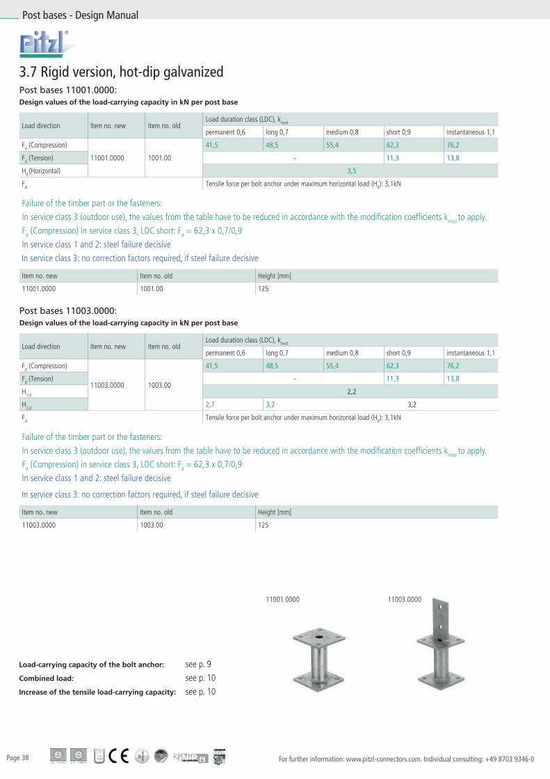
3.7 Rigid version, hot-dip galvanizedPost bases 11001.0000:Design values of the load-carrying capacity in kN per post base
Load direction Item no. new Item no. oldLoad duration class (LDC), kmod
permanent 0,6 long 0,7 medium 0,8 short 0,9 instantaneous 1,1
Fd (Compression)
11001.0000 1001.00
41,5 48,5 55,4 62,3 76,2
Fd (Tension) - 11,3 13,8
Hd (Horizontal) 3,5
FA Tensile force per bolt anchor under maximum horizontal load (Hd): 3,1kN
Failure of the timber part or the fasteners:
In service class 3 (outdoor use), the values from the table have to be reduced in accordance with the modification coefficients kmod to apply.
Fd (Compression) in service class 3, LDC short: Fd = 62,3 x 0,7/0,9
In service class 1 and 2: steel failure decisive
In service class 3: no correction factors required, if steel failure decisive
Item no. new Item no. old Height [mm]
11001.0000 1001.00 125
Post bases 11003.0000:Design values of the load-carrying capacity in kN per post base
Load direction Item no. new Item no. oldLoad duration class (LDC), kmod
permanent 0,6 long 0,7 medium 0,8 short 0,9 instantaneous 1,1
Fd (Compression)
11003.0000 1003.00
41,5 48,5 55,4 62,3 76,2
Fd (Tension) - 11,3 13,8
H1,d 2,2
H2,d 2,7 3,2 3,2
FA Tensile force per bolt anchor under maximum horizontal load (Hd): 3,1kN
Failure of the timber part or the fasteners:
In service class 3 (outdoor use), the values from the table have to be reduced in accordance with the modification coefficients kmod to apply.
Fd (Compression) in service class 3, LDC short: Fd = 62,3 x 0,7/0,9
In service class 1 and 2: steel failure decisive
In service class 3: no correction factors required, if steel failure decisive
Item no. new Item no. old Height [mm]
11003.0000 1003.00 125
11003.000011001.0000
Load-carrying capacity of the bolt anchor: see p. 9
Combined load: see p. 10
Increase of the tensile load-carrying capacity: see p. 10
Page 39
www.pitzl-connectors.com - Innovative wood connection systems for highest requirements.
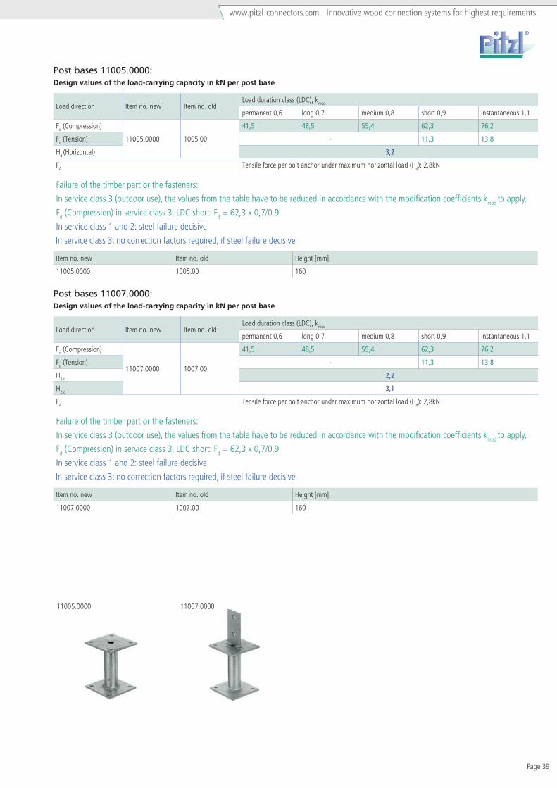
Post bases 11005.0000:Design values of the load-carrying capacity in kN per post base
Load direction Item no. new Item no. oldLoad duration class (LDC), kmod
permanent 0,6 long 0,7 medium 0,8 short 0,9 instantaneous 1,1
Fd (Compression)
11005.0000 1005.00
41,5 48,5 55,4 62,3 76,2
Fd (Tension) - 11,3 13,8
Hd (Horizontal) 3,2
FA Tensile force per bolt anchor under maximum horizontal load (Hd): 2,8kN
Failure of the timber part or the fasteners:
In service class 3 (outdoor use), the values from the table have to be reduced in accordance with the modification coefficients kmod to apply.
Fd (Compression) in service class 3, LDC short: Fd = 62,3 x 0,7/0,9
In service class 1 and 2: steel failure decisive
In service class 3: no correction factors required, if steel failure decisive
Item no. new Item no. old Height [mm]
11005.0000 1005.00 160
Post bases 11007.0000:Design values of the load-carrying capacity in kN per post base
Load direction Item no. new Item no. oldLoad duration class (LDC), kmod
permanent 0,6 long 0,7 medium 0,8 short 0,9 instantaneous 1,1
Fd (Compression)
11007.0000 1007.00
41,5 48,5 55,4 62,3 76,2
Fd (Tension) - 11,3 13,8
H1,d 2,2
H2,d 3,1
FA Tensile force per bolt anchor under maximum horizontal load (Hd): 2,8kN
Failure of the timber part or the fasteners:
In service class 3 (outdoor use), the values from the table have to be reduced in accordance with the modification coefficients kmod to apply.
Fd (Compression) in service class 3, LDC short: Fd = 62,3 x 0,7/0,9
In service class 1 and 2: steel failure decisive
In service class 3: no correction factors required, if steel failure decisive
Item no. new Item no. old Height [mm]
11007.0000 1007.00 160
11005.0000 11007.0000
For further information: www.pitzl-connectors.com. Individual consulting: +49 8703 9346-0Page 40
Post bases - Design Manual
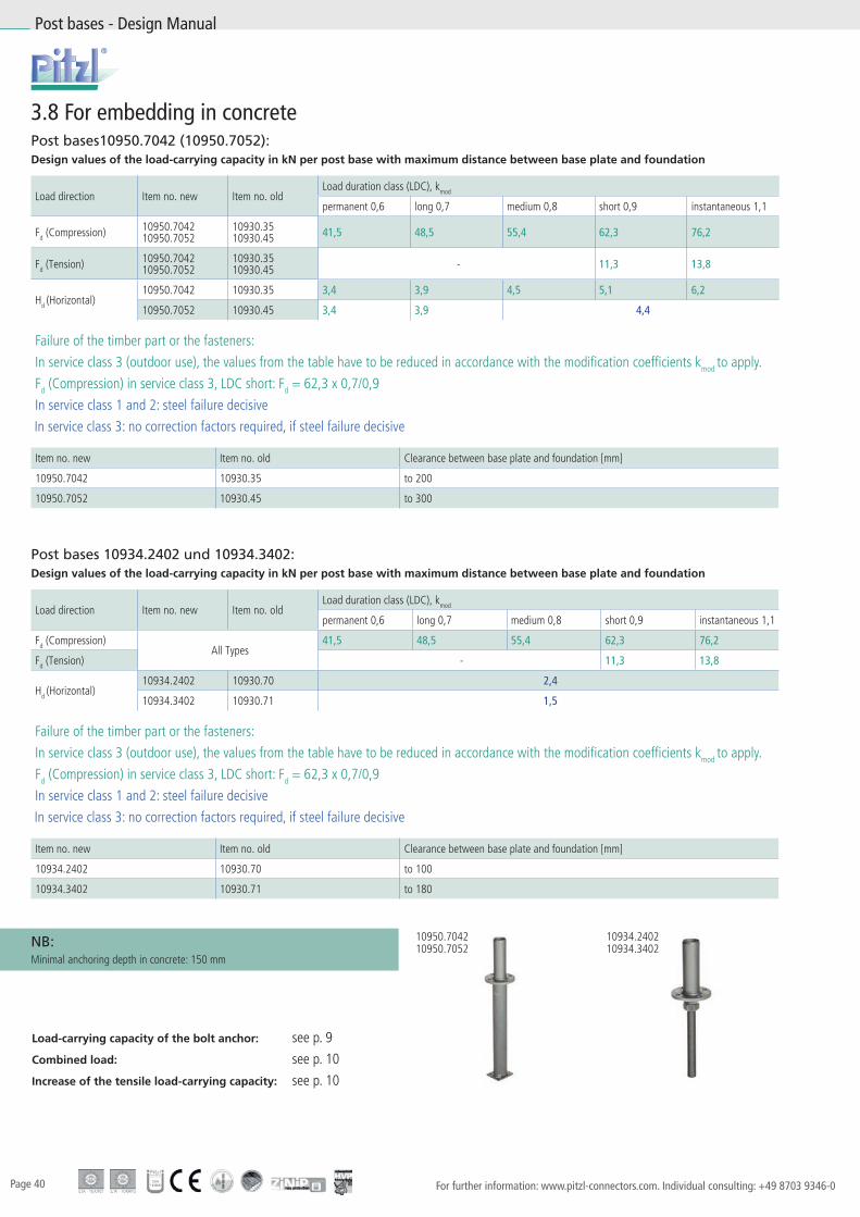
3.8 For embedding in concretePost bases10950.7042 (10950.7052):Design values of the load-carrying capacity in kN per post base with maximum distance between base plate and foundation
Load direction Item no. new Item no. oldLoad duration class (LDC), kmod
permanent 0,6 long 0,7 medium 0,8 short 0,9 instantaneous 1,1
Fd (Compression) 10950.7042 10950.7052
10930.35 10930.45 41,5 48,5 55,4 62,3 76,2
Fd (Tension) 10950.7042 10950.7052
10930.35 10930.45 - 11,3 13,8
Hd (Horizontal)10950.7042 10930.35 3,4 3,9 4,5 5,1 6,2
10950.7052 10930.45 3,4 3,9 4,4
Failure of the timber part or the fasteners:
In service class 3 (outdoor use), the values from the table have to be reduced in accordance with the modification coefficients kmod to apply.
Fd (Compression) in service class 3, LDC short: Fd = 62,3 x 0,7/0,9
In service class 1 and 2: steel failure decisive
In service class 3: no correction factors required, if steel failure decisive
Item no. new Item no. old Clearance between base plate and foundation [mm]
10950.7042 10930.35 to 200
10950.7052 10930.45 to 300
Post bases 10934.2402 und 10934.3402:Design values of the load-carrying capacity in kN per post base with maximum distance between base plate and foundation
Load direction Item no. new Item no. oldLoad duration class (LDC), kmod
permanent 0,6 long 0,7 medium 0,8 short 0,9 instantaneous 1,1
Fd (Compression)All Types
41,5 48,5 55,4 62,3 76,2
Fd (Tension) - 11,3 13,8
Hd (Horizontal)10934.2402 10930.70 2,4
10934.3402 10930.71 1,5
Failure of the timber part or the fasteners:
In service class 3 (outdoor use), the values from the table have to be reduced in accordance with the modification coefficients kmod to apply.
Fd (Compression) in service class 3, LDC short: Fd = 62,3 x 0,7/0,9
In service class 1 and 2: steel failure decisive
In service class 3: no correction factors required, if steel failure decisive
Item no. new Item no. old Clearance between base plate and foundation [mm]
10934.2402 10930.70 to 100
10934.3402 10930.71 to 180
10934.240210934.3402
10950.704210950.7052NB:
Minimal anchoring depth in concrete: 150 mm
Load-carrying capacity of the bolt anchor: see p. 9
Combined load: see p. 10
Increase of the tensile load-carrying capacity: see p. 10
Page 41
www.pitzl-connectors.com - Innovative wood connection systems for highest requirements.
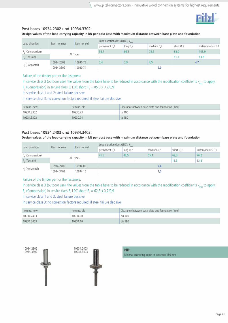
Post bases 10934.2302 und 10934.3302:Design values of the load-carrying capacity in kN per post base with maximum distance between base plate and foundation
Load direction Item no. new Item no. oldLoad duration class (LDC), kmod
permanent 0,6 long 0,7 medium 0,8 short 0,9 instantaneous 1,1
Fd (Compression)All Types
56,7 66,1 75,6 85,0 103,9
Fd (Tension) - 11,3 13,8
Hd (Horizontal)10934.2302 10930.73 3,4 3,9 4,5 4,7
10934.3302 10930.74 2,9
Failure of the timber part or the fasteners:
In service class 3 (outdoor use), the values from the table have to be reduced in accordance with the modification coefficients kmod to apply.
Fd (Compression) in service class 3, LDC short: Fd = 85,0 x 0,7/0,9
In service class 1 and 2: steel failure decisive
In service class 3: no correction factors required, if steel failure decisive
Item no. new Item no. old Clearance between base plate and foundation [mm]
10934.2302 10930.73 to 100
10934.3302 10930.74 to 180
Post bases 10934.2403 und 10934.3403:Design values of the load-carrying capacity in kN per post base with maximum distance between base plate and foundation
Load direction Item no. new Item no. oldLoad duration class (LDC), kmod
permanent 0,6 long 0,7 medium 0,8 short 0,9 instantaneous 1,1
Fd (Compression)All Types
41,5 48,5 55,4 62,3 76,2
Fd (Tension) - 11,3 13,8
Hd (Horizontal)10934.2403 10934.00 2,4
10934.3403 10934.10 1,5
Failure of the timber part or the fasteners:
In service class 3 (outdoor use), the values from the table have to be reduced in accordance with the modification coefficients kmod to apply.
Fd (Compression) in service class 3, LDC short: Fd = 62,3 x 0,7/0,9
In service class 1 and 2: steel failure decisive
In service class 3: no correction factors required, if steel failure decisive
Item no. new Item no. old Clearance between base plate and foundation [mm]
10934.2403 10934.00 bis 100
10934.3403 10934.10 bis 180
10934.230210934.3302
10934.240310934.3403 NB:
Minimal anchoring depth in concrete: 150 mm
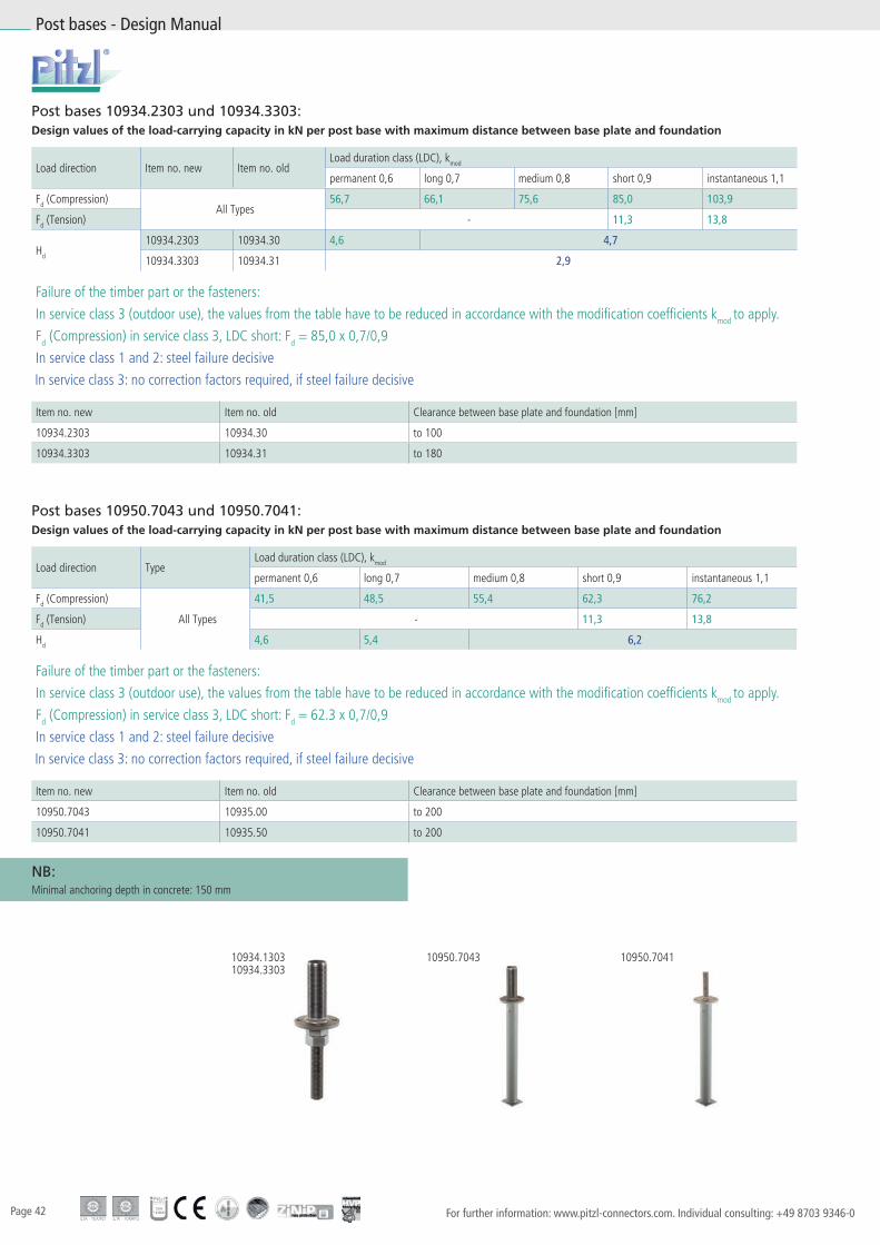
For further information: www.pitzl-connectors.com. Individual consulting: +49 8703 9346-0Page 42
Post bases - Design Manual
Post bases 10934.2303 und 10934.3303:Design values of the load-carrying capacity in kN per post base with maximum distance between base plate and foundation
Load direction Item no. new Item no. oldLoad duration class (LDC), kmod
permanent 0,6 long 0,7 medium 0,8 short 0,9 instantaneous 1,1
Fd (Compression)All Types
56,7 66,1 75,6 85,0 103,9
Fd (Tension) - 11,3 13,8
Hd
10934.2303 10934.30 4,6 4,7
10934.3303 10934.31 2,9
Failure of the timber part or the fasteners:
In service class 3 (outdoor use), the values from the table have to be reduced in accordance with the modification coefficients kmod to apply.
Fd (Compression) in service class 3, LDC short: Fd = 85,0 x 0,7/0,9
In service class 1 and 2: steel failure decisive
In service class 3: no correction factors required, if steel failure decisive
Item no. new Item no. old Clearance between base plate and foundation [mm]
10934.2303 10934.30 to 100
10934.3303 10934.31 to 180
Post bases 10950.7043 und 10950.7041:Design values of the load-carrying capacity in kN per post base with maximum distance between base plate and foundation
Load direction TypeLoad duration class (LDC), kmod
permanent 0,6 long 0,7 medium 0,8 short 0,9 instantaneous 1,1
Fd (Compression)
All Types
41,5 48,5 55,4 62,3 76,2
Fd (Tension) - 11,3 13,8
Hd 4,6 5,4 6,2
Failure of the timber part or the fasteners:
In service class 3 (outdoor use), the values from the table have to be reduced in accordance with the modification coefficients kmod to apply.
Fd (Compression) in service class 3, LDC short: Fd = 62.3 x 0,7/0,9
In service class 1 and 2: steel failure decisive
In service class 3: no correction factors required, if steel failure decisive
Item no. new Item no. old Clearance between base plate and foundation [mm]
10950.7043 10935.00 to 200
10950.7041 10935.50 to 200
10950.7043 10950.7041 10934.130310934.3303
NB:Minimal anchoring depth in concrete: 150 mm
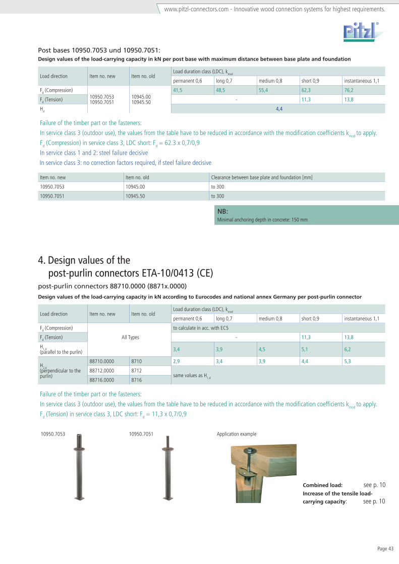
Page 43
www.pitzl-connectors.com - Innovative wood connection systems for highest requirements.
Post bases 10950.7053 und 10950.7051:Design values of the load-carrying capacity in kN per post base with maximum distance between base plate and foundation
Load direction Item no. new Item no. oldLoad duration class (LDC), kmod
permanent 0,6 long 0,7 medium 0,8 short 0,9 instantaneous 1,1
Fd (Compression)10950.7053 10950.7051
10945.00 10945.50
41,5 48,5 55,4 62,3 76,2
Fd (Tension) - 11,3 13,8
Hd 4,4
Failure of the timber part or the fasteners:
In service class 3 (outdoor use), the values from the table have to be reduced in accordance with the modification coefficients kmod to apply.
Fd (Compression) in service class 3, LDC short: Fd = 62.3 x 0,7/0,9
In service class 1 and 2: steel failure decisive
In service class 3: no correction factors required, if steel failure decisive
Item no. new Item no. old Clearance between base plate and foundation [mm]
10950.7053 10945.00 to 300
10950.7051 10945.50 to 300
4. Design values of the post-purlin connectors ETA-10/0413 (CE)post-purlin connectors 88710.0000 (8871x.0000)
Design values of the load-carrying capacity in kN according to Eurocodes and national annex Germany per post-purlin connector
Load direction Item no. new Item no. oldLoad duration class (LDC), kmod
permanent 0,6 long 0,7 medium 0,8 short 0,9 instantaneous 1,1
Fd (Compression)
All Types
to calculate in acc. with EC5
Fd (Tension) - 11,3 13,8
H1,d (parallel to the purlin) 3,4 3,9 4,5 5,1 6,2
H2,d (perpendicular to the purlin)
88710.0000 8710 2,9 3,4 3,9 4,4 5,3
88712.0000 8712same values as H1,d88716.0000 8716
Failure of the timber part or the fasteners:
In service class 3 (outdoor use), the values from the table have to be reduced in accordance with the modification coefficients kmod to apply.
Fd (Tension) in service class 3, LDC short: Fd = 11,3 x 0,7/0,9
Application example10950.7053 10950.7051
NB:Minimal anchoring depth in concrete: 150 mm
Combined load: see p. 10Increase of the tensile load-
carrying capacity: see p. 10
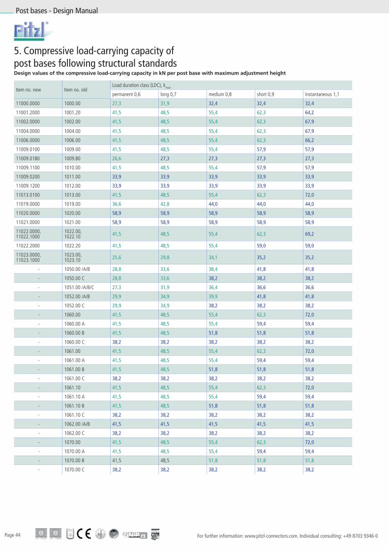
For further information: www.pitzl-connectors.com. Individual consulting: +49 8703 9346-0Page 44
Post bases - Design Manual
5. Compressive load-carrying capacity of post bases following structural standardsDesign values of the compressive load-carrying capacity in kN per post base with maximum adjustment height
Item no. new Item no. oldLoad duration class (LDC), kmod
permanent 0,6 long 0,7 medium 0,8 short 0,9 instantaneous 1,1
11000.0000 1000.00 27,3 31,9 32,4 32,4 32,4
11001.2000 1001.20 41,5 48,5 55,4 62,3 64,2
11002.0000 1002.00 41,5 48,5 55,4 62,3 67,9
11004.0000 1004.00 41,5 48,5 55,4 62,3 67,9
11006.0000 1006.00 41,5 48,5 55,4 62,3 66,2
11009.0100 1009.00 41,5 48,5 55,4 57,9 57,9
11009.0180 1009.80 26,6 27,3 27,3 27,3 27,3
11009.1100 1010.00 41,5 48,5 55,4 57,9 57,9
11009.0200 1011.00 33,9 33,9 33,9 33,9 33,9
11009.1200 1012.00 33,9 33,9 33,9 33,9 33,9
11013.0100 1013.00 41,5 48,5 55,4 62,3 72,0
11019.0000 1019.00 36,6 42,8 44,0 44,0 44,0
11020.0000 1020.00 58,9 58,9 58,9 58,9 58,9
11021.0000 1021.00 58,9 58,9 58,9 58,9 58,9
11022.0000, 11022.1000
1022.00, 1022.10 41,5 48,5 55,4 62,3 69,2
11022.2000 1022.20 41,5 48,5 55,4 59,0 59,0
11023.0000, 11023.1000
1023.00, 1023.10 25,6 29,8 34,1 35,2 35,2
- 1050.00 /A/B 28,8 33,6 38,4 41,8 41,8
- 1050.00 C 28,8 33,6 38,2 38,2 38,2
- 1051.00 /A/B/C 27,3 31,9 36,4 36,6 36,6
- 1052.00 /A/B 29,9 34,9 39,9 41,8 41,8
- 1052.00 C 29,9 34,9 38,2 38,2 38,2
- 1060.00 41,5 48,5 55,4 62,3 72,0
- 1060.00 A 41,5 48,5 55,4 59,4 59,4
- 1060.00 B 41,5 48,5 51,8 51,8 51,8
- 1060.00 C 38,2 38,2 38,2 38,2 38,2
- 1061.00 41,5 48,5 55,4 62,3 72,0
- 1061.00 A 41,5 48,5 55,4 59,4 59,4
- 1061.00 B 41,5 48,5 51,8 51,8 51,8
- 1061.00 C 38,2 38,2 38,2 38,2 38,2
- 1061.10 41,5 48,5 55,4 62,3 72,0
- 1061.10 A 41,5 48,5 55,4 59,4 59,4
- 1061.10 B 41,5 48,5 51,8 51,8 51,8
- 1061.10 C 38,2 38,2 38,2 38,2 38,2
- 1062.00 /A/B 41,5 41,5 41,5 41,5 41,5
- 1062.00 C 38,2 38,2 38,2 38,2 38,2
- 1070.00 41,5 48,5 55,4 62,3 72,0
- 1070.00 A 41,5 48,5 55,4 59,4 59,4
- 1070.00 B 41,5 48,5 51,8 51,8 51,8
- 1070.00 C 38,2 38,2 38,2 38,2 38,2
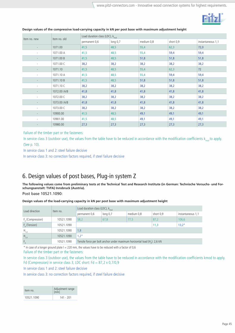
Page 45
www.pitzl-connectors.com - Innovative wood connection systems for highest requirements.
Item no. new Item no. oldLoad duration class (LDC), kmod
permanent 0,6 long 0,7 medium 0,8 short 0,9 instantaneous 1,1
- 1071.00 41,5 48,5 55,4 62,3 72,0
- 1071.00 A 41,5 48,5 55,4 59,4 59,4
- 1071.00 B 41,5 48,5 51,8 51,8 51,8
- 1071.00 C 38,2 38,2 38,2 38,2 38,2
- 1071.10 41,5 48,5 55,4 62,3 72
- 1071.10 A 41,5 48,5 55,4 59,4 59,4
- 1071.10 B 41,5 48,5 51,8 51,8 51,8
- 1071.10 C 38,2 38,2 38,2 38,2 38,2
- 1072.00 /A/B 41,8 41,8 41,8 41,8 41,8
- 1072.00 C 38,2 38,2 38,2 38,2 38,2
- 1073.00 /A/B 41,8 41,8 41,8 41,8 41,8
- 1073.00 C 38,2 38,2 38,2 38,2 38,2
- 10900.00 41,5 48,5 49,1 49,1 49,1
- 10901.00 41,5 48,5 49,1 49,1 49,1
- 10980.00 27,3 27,3 27,3 27,3 27,3
Failure of the timber part or the fasteners:
In service class 3 (outdoor use), the values from the table have to be reduced in accordance with the modification coefficients kmod to apply.
(See p. 10).
In service class 1 and 2: steel failure decisive
In service class 3: no correction factors required, if steel failure decisive
Design values of the compressive load-carrying capacity in kN per post base with maximum adjustment height
6. Design values of post bases, Plug-in system ZThe following values come from preliminary tests at the Technical Test and Research Institute (in German: Technische Versuchs- und For-schungsanstalt: TVFA) Innsbruck (Austria).
Post base 10521.1090:
Design values of the load-carrying capacity in kN per post base with maximum adjustment height
Load direction Item no.Load duration class (LDC), kmod
permanent 0,6 long 0,7 medium 0,8 short 0,9 instantaneous 1,1
Fd (Compression) 10521.1090 58,2 67,8 77,5 87,2 106,6
Fd (Tension) 10521.1090 11,3 13,2*
H1,d 10521.1090 1,8
H2,d 10521.1090 1,2*
FA 10521.1090 Tensile force per bolt anchor under maximum horizontal load (Hd): 2,6 kN
* In case of a longer ground plate l = 220 mm, the values have to be reduced with a factor of 0,6
Failure of the timber part or the fasteners:
In service class 3 (outdoor use), the values from the table have to be reduced in accordance with the modification coefficients kmod to apply. Fd (Compression) in service class 3, LDC short: Fd = 87,2 x 0,7/0,9
In service class 1 and 2: steel failure decisive
In service class 3: no correction factors required, if steel failure decisive
Item no. Adjustment range[mm]
10521.1090 141 - 201
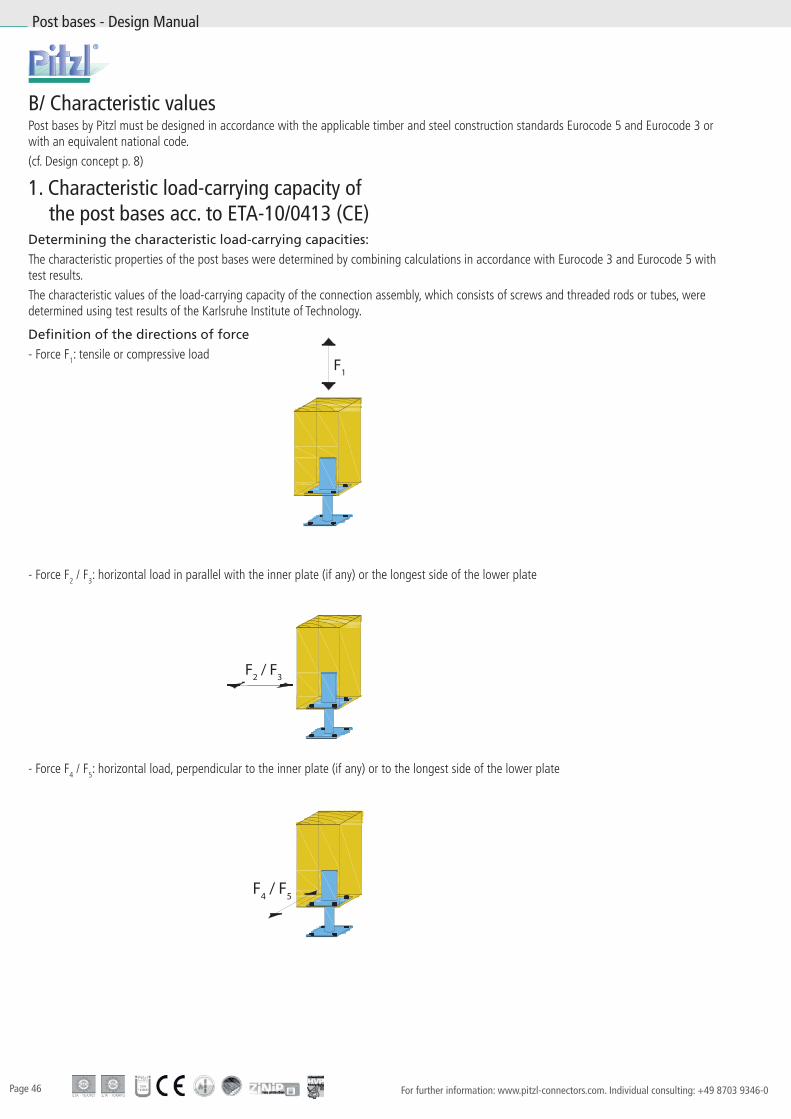
For further information: www.pitzl-connectors.com. Individual consulting: +49 8703 9346-0Page 46
Post bases - Design Manual
B/ Characteristic valuesPost bases by Pitzl must be designed in accordance with the applicable timber and steel construction standards Eurocode 5 and Eurocode 3 or with an equivalent national code.
(cf. Design concept p. 8)
1. Characteristic load-carrying capacity of the post bases acc. to ETA-10/0413 (CE)Determining the characteristic load-carrying capacities:
The characteristic properties of the post bases were determined by combining calculations in accordance with Eurocode 3 and Eurocode 5 with test results.
The characteristic values of the load-carrying capacity of the connection assembly, which consists of screws and threaded rods or tubes, were determined using test results of the Karlsruhe Institute of Technology.
Definition of the directions of force
- Force F1: tensile or compressive load
- Force F2 / F3: horizontal load in parallel with the inner plate (if any) or the longest side of the lower plate
- Force F4 / F5: horizontal load, perpendicular to the inner plate (if any) or to the longest side of the lower plate
F1
F2 / F3
F4 / F5
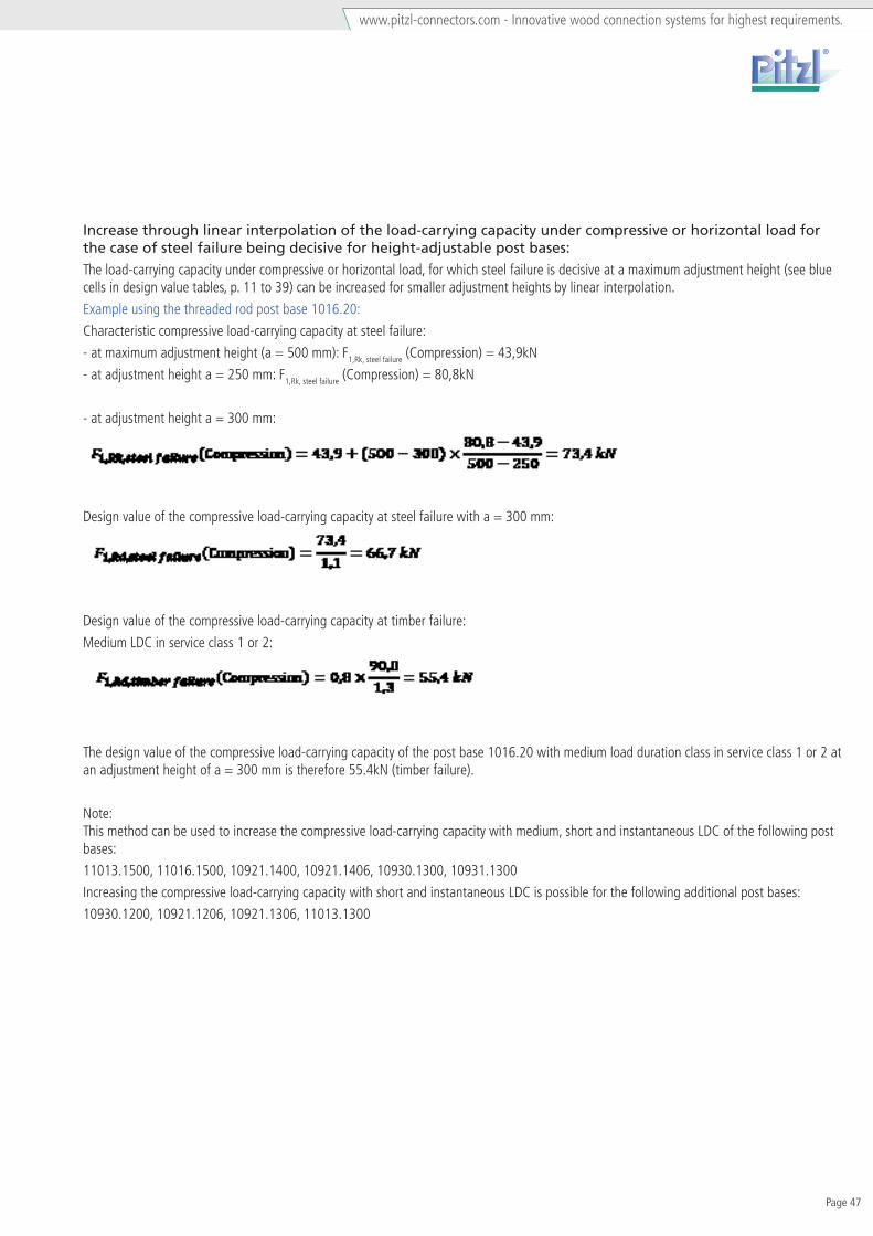
Page 47
www.pitzl-connectors.com - Innovative wood connection systems for highest requirements.
Increase through linear interpolation of the load-carrying capacity under compressive or horizontal load for the case of steel failure being decisive for height-adjustable post bases:
The load-carrying capacity under compressive or horizontal load, for which steel failure is decisive at a maximum adjustment height (see blue cells in design value tables, p. 11 to 39) can be increased for smaller adjustment heights by linear interpolation.
Example using the threaded rod post base 1016.20:
Characteristic compressive load-carrying capacity at steel failure:
- at maximum adjustment height (a = 500 mm): F1,Rk, steel failure (Compression) = 43,9kN
- at adjustment height a = 250 mm: F1,Rk, steel failure (Compression) = 80,8kN
- at adjustment height a = 300 mm:
Design value of the compressive load-carrying capacity at steel failure with a = 300 mm:
Design value of the compressive load-carrying capacity at timber failure:
Medium LDC in service class 1 or 2:
The design value of the compressive load-carrying capacity of the post base 1016.20 with medium load duration class in service class 1 or 2 at an adjustment height of a = 300 mm is therefore 55.4kN (timber failure).
Note: This method can be used to increase the compressive load-carrying capacity with medium, short and instantaneous LDC of the following post bases:
11013.1500, 11016.1500, 10921.1400, 10921.1406, 10930.1300, 10931.1300
Increasing the compressive load-carrying capacity with short and instantaneous LDC is possible for the following additional post bases:
10930.1200, 10921.1206, 10921.1306, 11013.1300
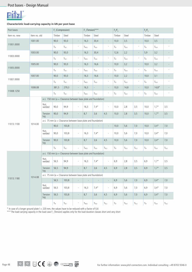
For further information: www.pitzl-connectors.com. Individual consulting: +49 8703 9346-0Page 48
Post bases - Design Manual
Characteristic load-carrying capacity in kN per post base
Post bases F1 (Compression) F1 (Tension)*** F2/F3 F4/F5
Item no. new Item no. old Timber Steel Timber Steel Timber Steel Timber Steel
11001.00001001.00 90,0 93,0 - 16,3 30,4 - 10,0 3,5 - 10,0 3,5 -
gM gM,1 - gM(C) gM,0 - gM gM,0 - gM gM,0 -
11003.00001003.00 90,0 93,0 - 16,3 30,4 - 12,6 2,2 - 5,9 3,2 -
gM gM,1 - gM(C) gM,0 - gM gM,0 - gM gM,0 -
11005.00001005.00 90,0 93,0 - 16,3 16,6 - 10,0 3,2 - 10,0 3,2 -
gM gM,1 - gM(C) gM,0 - gM gM,0 - gM gM,0 -
11007.00001007.00 90,0 93,0 - 16,3 16,6 - 10,0 2,2 - 10,0 3,1 -
gM gM,1 - gM(C) gM,0 - gM gM,0 - gM gM,0 -
11008.12501008.08 381,5 279,3 - 16,3 - - 10,0 14,8 - 10,0 14,8* -
gM gM,1 - gM(C) gM,0 - gM gM,0 - gM gM,0 -
11013.1100 1014.00
a ≤ 150 mm (a = Clearance between base plate and foundation)
Nut, welded 90,0 94,9 - 16,3 7,4* - 10,0 2,8 3,5 10,0 1,7* 3,5
Tension lug
90,0 94,9 - 8,7 3,6 4,5 10,0 2,8 3,5 10,0 1,7* 3,5
a ≤ 75 mm (a = Clearance between base plate and foundation)
90,0 103,8 - - - - 10,0 5,6 7,0 10,0 3,4* 7,0
Nut, welded 90,0 103,8 - 16,3 7,4* - 10,0 5,6 7,0 10,0 3,4* 7,0
Tension lug
90,0 103,8 - 8,7 3,6 4,5 10,0 5,6 7,0 10,0 3,4* 7,0
gM gM,1 - gM(C) gM,0 gM,2 gM gM,0 gM,2 gM gM,0 gM,2
11013.1180 1014.08
a ≤ 150 mm (a = Clearance between base plate and foundation)
Nut, welded 56,5 94,9 - 16,3 7,4* - 6,9 2,8 3,5 6,9 1,7* 3,5
Tension lug
56,5 94,9 - 8,7 3,6 4,5 6,9 2,8 3,5 6,9 1,7* 3,5
a ≤ 75 mm (a = Clearance between base plate and foundation)
56,5 103,8 - - - - 6,9 5,6 7,0 6,9 3,4* 7,0
Nut, welded 56,5 103,8 - 16,3 7,4* - 6,9 5,6 7,0 6,9 3,4* 7,0
Tension lug
56,5 103,8 - 8,7 3,6 4,5 6,9 5,6 7,0 6,9 3,4* 7,0
gM gM,1 - gM(C) gM,0 gM,2 gM gM,0 gM,2 gM gM,0 gM,2
* In case of a longer ground plate l = 220 mm, the values have to be reduced with a factor of 0,6 *** The load-carrying capacity in the load case F1 (Tension) applies only for the load duration classes short and very short
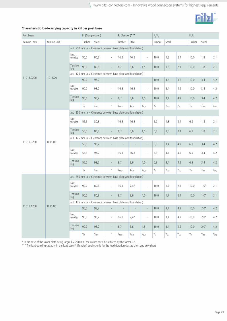
Page 49
www.pitzl-connectors.com - Innovative wood connection systems for highest requirements.
Characteristic load-carrying capacity in kN per post base
Post bases F1 (Compression) F1 (Tension)*** F2/F3 F4/F5
Item no. new Item no. old Timber Steel Timber Steel Timber Steel Timber Steel
11013.0200 1015.00
a ≤ 250 mm (a = Clearance between base plate and foundation)
Nut, welded 90,0 80,8 - 16,3 16,8 - 10,0 1,8 2,1 10,0 1,8 2,1
Tension lug 90,0 80,8 - 8,7 3,6 4,5 10,0 1,8 2,1 10,0 1,8 2,1
a ≤ 125 mm (a = Clearance between base plate and foundation)
90,0 98,2 - - - - 10,0 3,4 4,2 10,0 3,4 4,2
Nut, welded 90,0 98,2 - 16,3 16,8 - 10,0 3,4 4,2 10,0 3,4 4,2
Tension lug 90,0 98,2 - 8,7 3,6 4,5 10,0 3,4 4,2 10,0 3,4 4,2
gM gM,1 - gM(C) gM,0 gM,2 gM gM,0 gM,2 gM gM,0 gM,2
11013.0280 1015.08
a ≤ 250 mm (a = Clearance between base plate and foundation)
Nut, welded 56,5 80,8 - 16,3 16,8 - 6,9 1,8 2,1 6,9 1,8 2,1
Tension lug 56,5 80,8 - 8,7 3,6 4,5 6,9 1,8 2,1 6,9 1,8 2,1
a ≤ 125 mm (a = Clearance between base plate and foundation)
56,5 98,2 - - - - 6,9 3,4 4,2 6,9 3,4 4,2
Nut, welded 56,5 98,2 - 16,3 16,8 - 6,9 3,4 4,2 6,9 3,4 4,2
Tension lug 56,5 98,2 - 8,7 3,6 4,5 6,9 3,4 4,2 6,9 3,4 4,2
gM gM,1 - gM(C) gM,0 gM,2 gM gM,0 gM,2 gM gM,0 gM,2
11013.1200 1016.00
a ≤ 250 mm (a = Clearance between base plate and foundation)
Nut, welded 90,0 80,8 - 16,3 7,4* - 10,0 1,7 2,1 10,0 1,0* 2,1
Tension lug 90,0 80,8 - 8,7 3,6 4,5 10,0 1,7 2,1 10,0 1,0* 2,1
a ≤ 125 mm (a = Clearance between base plate and foundation)
90,0 98,2 - - - - 10,0 3,4 4,2 10,0 2,0* 4,2
Nut, welded 90,0 98,2 - 16,3 7,4* - 10,0 3,4 4,2 10,0 2,0* 4,2
Tension lug 90,0 98,2 - 8,7 3,6 4,5 10,0 3,4 4,2 10,0 2,0* 4,2
gM gM,1 - gM(C) gM,0 gM,2 gM gM,0 gM,2 gM gM,0 gM,2
* In the case of the lower plate being larger, l = 220 mm, the values must be reduced by the factor 0.6 *** The load-carrying capacity in the load case F1 (Tension) applies only for the load duration classes short and very short
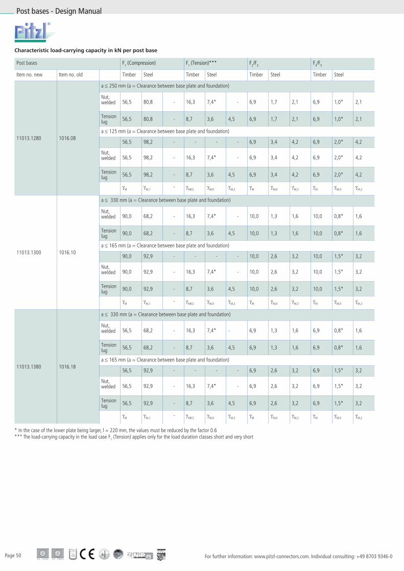
For further information: www.pitzl-connectors.com. Individual consulting: +49 8703 9346-0Page 50
Post bases - Design Manual
Characteristic load-carrying capacity in kN per post base
Post bases F1 (Compression) F1 (Tension)*** F2/F3 F4/F5
Item no. new Item no. old Timber Steel Timber Steel Timber Steel Timber Steel
11013.1280 1016.08
a ≤ 250 mm (a = Clearance between base plate and foundation)
Nut, welded 56,5 80,8 - 16,3 7,4* - 6,9 1,7 2,1 6,9 1,0* 2,1
Tension lug 56,5 80,8 - 8,7 3,6 4,5 6,9 1,7 2,1 6,9 1,0* 2,1
a ≤ 125 mm (a = Clearance between base plate and foundation)
56,5 98,2 - - - - 6,9 3,4 4,2 6,9 2,0* 4,2
Nut, welded 56,5 98,2 - 16,3 7,4* - 6,9 3,4 4,2 6,9 2,0* 4,2
Tension lug 56,5 98,2 - 8,7 3,6 4,5 6,9 3,4 4,2 6,9 2,0* 4,2
gM gM,1 - gM(C) gM,0 gM,2 gM gM,0 gM,2 gM gM,0 gM,2
11013.1300 1016.10
a ≤ 330 mm (a = Clearance between base plate and foundation)
Nut, welded 90,0 68,2 - 16,3 7,4* - 10,0 1,3 1,6 10,0 0,8* 1,6
Tension lug 90,0 68,2 - 8,7 3,6 4,5 10,0 1,3 1,6 10,0 0,8* 1,6
a ≤ 165 mm (a = Clearance between base plate and foundation)
90,0 92,9 - - - - 10,0 2,6 3,2 10,0 1,5* 3,2
Nut, welded 90,0 92,9 - 16,3 7,4* - 10,0 2,6 3,2 10,0 1,5* 3,2
Tension lug 90,0 92,9 - 8,7 3,6 4,5 10,0 2,6 3,2 10,0 1,5* 3,2
gM gM,1 - gM(C) gM,0 gM,2 gM gM,0 gM,2 gM gM,0 gM,2
11013.1380 1016.18
a ≤ 330 mm (a = Clearance between base plate and foundation)
Nut, welded 56,5 68,2 - 16,3 7,4* - 6,9 1,3 1,6 6,9 0,8* 1,6
Tension lug 56,5 68,2 - 8,7 3,6 4,5 6,9 1,3 1,6 6,9 0,8* 1,6
a ≤ 165 mm (a = Clearance between base plate and foundation)
56,5 92,9 - - - - 6,9 2,6 3,2 6,9 1,5* 3,2
Nut, welded 56,5 92,9 - 16,3 7,4* - 6,9 2,6 3,2 6,9 1,5* 3,2
Tension lug 56,5 92,9 - 8,7 3,6 4,5 6,9 2,6 3,2 6,9 1,5* 3,2
gM gM,1 - gM(C) gM,0 gM,2 gM gM,0 gM,2 gM gM,0 gM,2
* In the case of the lower plate being larger, l = 220 mm, the values must be reduced by the factor 0.6 *** The load-carrying capacity in the load case F1 (Tension) applies only for the load duration classes short and very short
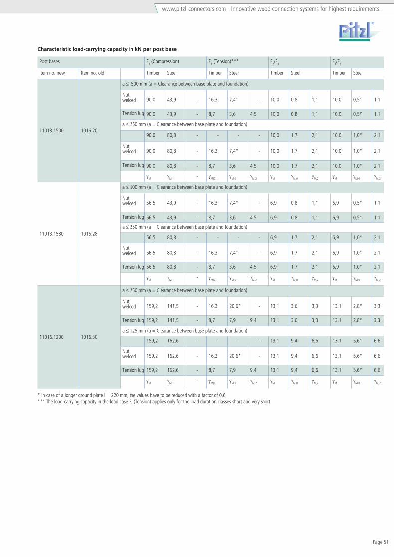
Page 51
www.pitzl-connectors.com - Innovative wood connection systems for highest requirements.
Characteristic load-carrying capacity in kN per post base
Post bases F1 (Compression) F1 (Tension)*** F2/F3 F4/F5
Item no. new Item no. old Timber Steel Timber Steel Timber Steel Timber Steel
11013.1500 1016.20
a ≤ 500 mm (a = Clearance between base plate and foundation)
Nut, welded 90,0 43,9 - 16,3 7,4* - 10,0 0,8 1,1 10,0 0,5* 1,1
Tension lug 90,0 43,9 - 8,7 3,6 4,5 10,0 0,8 1,1 10,0 0,5* 1,1
a ≤ 250 mm (a = Clearance between base plate and foundation)
90,0 80,8 - - - - 10,0 1,7 2,1 10,0 1,0* 2,1
Nut, welded 90,0 80,8 - 16,3 7,4* - 10,0 1,7 2,1 10,0 1,0* 2,1
Tension lug 90,0 80,8 - 8,7 3,6 4,5 10,0 1,7 2,1 10,0 1,0* 2,1
gM gM,1 - gM(C) gM,0 gM,2 gM gM,0 gM,2 gM gM,0 gM,2
11013.1580 1016.28
a ≤ 500 mm (a = Clearance between base plate and foundation)
Nut, welded 56,5 43,9 - 16,3 7,4* - 6,9 0,8 1,1 6,9 0,5* 1,1
Tension lug 56,5 43,9 - 8,7 3,6 4,5 6,9 0,8 1,1 6,9 0,5* 1,1
a ≤ 250 mm (a = Clearance between base plate and foundation)
56,5 80,8 - - - - 6,9 1,7 2,1 6,9 1,0* 2,1
Nut, welded 56,5 80,8 - 16,3 7,4* - 6,9 1,7 2,1 6,9 1,0* 2,1
Tension lug 56,5 80,8 - 8,7 3,6 4,5 6,9 1,7 2,1 6,9 1,0* 2,1
gM gM,1 - gM(C) gM,0 gM,2 gM gM,0 gM,2 gM gM,0 gM,2
11016.1200 1016.30
a ≤ 250 mm (a = Clearance between base plate and foundation)
Nut, welded 159,2 141,5 - 16,3 20,6* - 13,1 3,6 3,3 13,1 2,8* 3,3
Tension lug 159,2 141,5 - 8,7 7,9 9,4 13,1 3,6 3,3 13,1 2,8* 3,3
a ≤ 125 mm (a = Clearance between base plate and foundation)
159,2 162,6 - - - - 13,1 9,4 6,6 13,1 5,6* 6,6
Nut, welded 159,2 162,6 - 16,3 20,6* - 13,1 9,4 6,6 13,1 5,6* 6,6
Tension lug 159,2 162,6 - 8,7 7,9 9,4 13,1 9,4 6,6 13,1 5,6* 6,6
gM gM,1 - gM(C) gM,0 gM,2 gM gM,0 gM,2 gM gM,0 gM,2
* In case of a longer ground plate l = 220 mm, the values have to be reduced with a factor of 0,6 *** The load-carrying capacity in the load case F1 (Tension) applies only for the load duration classes short and very short
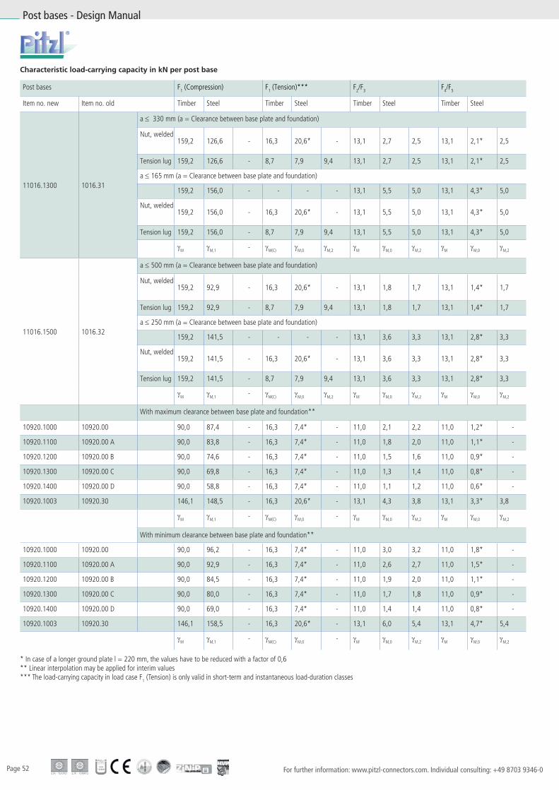
For further information: www.pitzl-connectors.com. Individual consulting: +49 8703 9346-0Page 52
Post bases - Design Manual
Characteristic load-carrying capacity in kN per post base
Post bases F1 (Compression) F1 (Tension)*** F2/F3 F4/F5
Item no. new Item no. old Timber Steel Timber Steel Timber Steel Timber Steel
11016.1300 1016.31
a ≤ 330 mm (a = Clearance between base plate and foundation)
Nut, welded159,2 126,6 - 16,3 20,6* - 13,1 2,7 2,5 13,1 2,1* 2,5
Tension lug 159,2 126,6 - 8,7 7,9 9,4 13,1 2,7 2,5 13,1 2,1* 2,5
a ≤ 165 mm (a = Clearance between base plate and foundation)
159,2 156,0 - - - - 13,1 5,5 5,0 13,1 4,3* 5,0
Nut, welded159,2 156,0 - 16,3 20,6* - 13,1 5,5 5,0 13,1 4,3* 5,0
Tension lug 159,2 156,0 - 8,7 7,9 9,4 13,1 5,5 5,0 13,1 4,3* 5,0
gM gM,1 - gM(C) gM,0 gM,2 gM gM,0 gM,2 gM gM,0 gM,2
11016.1500 1016.32
a ≤ 500 mm (a = Clearance between base plate and foundation)
Nut, welded159,2 92,9 - 16,3 20,6* - 13,1 1,8 1,7 13,1 1,4* 1,7
Tension lug 159,2 92,9 - 8,7 7,9 9,4 13,1 1,8 1,7 13,1 1,4* 1,7
a ≤ 250 mm (a = Clearance between base plate and foundation)
159,2 141,5 - - - - 13,1 3,6 3,3 13,1 2,8* 3,3
Nut, welded159,2 141,5 - 16,3 20,6* - 13,1 3,6 3,3 13,1 2,8* 3,3
Tension lug 159,2 141,5 - 8,7 7,9 9,4 13,1 3,6 3,3 13,1 2,8* 3,3
gM gM,1 - gM(C) gM,0 gM,2 gM gM,0 gM,2 gM gM,0 gM,2
With maximum clearance between base plate and foundation**
10920.1000 10920.00 90,0 87,4 - 16,3 7,4* - 11,0 2,1 2,2 11,0 1,2* -
10920.1100 10920.00 A 90,0 83,8 - 16,3 7,4* - 11,0 1,8 2,0 11,0 1,1* -
10920.1200 10920.00 B 90,0 74,6 - 16,3 7,4* - 11,0 1,5 1,6 11,0 0,9* -
10920.1300 10920.00 C 90,0 69,8 - 16,3 7,4* - 11,0 1,3 1,4 11,0 0,8* -
10920.1400 10920.00 D 90,0 58,8 - 16,3 7,4* - 11,0 1,1 1,2 11,0 0,6* -
10920.1003 10920.30 146,1 148,5 - 16,3 20,6* - 13,1 4,3 3,8 13,1 3,3* 3,8
gM gM,1 - gM(C) gM,0 - gM gM,0 gM,2 gM gM,0 gM,2
With minimum clearance between base plate and foundation**
10920.1000 10920.00 90,0 96,2 - 16,3 7,4* - 11,0 3,0 3,2 11,0 1,8* -
10920.1100 10920.00 A 90,0 92,9 - 16,3 7,4* - 11,0 2,6 2,7 11,0 1,5* -
10920.1200 10920.00 B 90,0 84,5 - 16,3 7,4* - 11,0 1,9 2,0 11,0 1,1* -
10920.1300 10920.00 C 90,0 80,0 - 16,3 7,4* - 11,0 1,7 1,8 11,0 0,9* -
10920.1400 10920.00 D 90,0 69,0 - 16,3 7,4* - 11,0 1,4 1,4 11,0 0,8* -
10920.1003 10920.30 146,1 158,5 - 16,3 20,6* - 13,1 6,0 5,4 13,1 4,7* 5,4
gM gM,1 - gM(C) gM,0 - gM gM,0 gM,2 gM gM,0 gM,2
* In case of a longer ground plate l = 220 mm, the values have to be reduced with a factor of 0,6 ** Linear interpolation may be applied for interim values *** The load-carrying capacity in load case F1 (Tension) is only valid in short-term and instantaneous load-duration classes
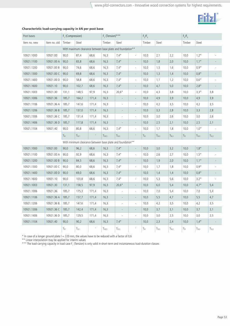
Page 53
www.pitzl-connectors.com - Innovative wood connection systems for highest requirements.
Characteristic load-carrying capacity in kN per post base
Post bases F1 (Compression) F1 (Tension)*** F2/F3 F4/F5
Item no. new Item no. old Timber Steel Timber Steel Timber Steel Timber Steel
With maximum clearance between base plate and foundation**
10921.1000 10921.00 90,0 87,4 68,6 16,3 7,4* - 10,0 2,1 2,2 10,0 1,2* -
10921.1100 10921.00 A 90,0 83,8 68,6 16,3 7,4* - 10,0 1,8 2,0 10,0 1,1* -
10921.1200 10921.00 B 90,0 74,6 68,6 16,3 7,4* - 10,0 1,5 1,6 10,0 0,9* -
10921.1300 10921.00 C 90,0 69,8 68,6 16,3 7,4* - 10,0 1,3 1,4 10,0 0,8* -
10921.1400 10921.00 D 90,0 58,8 68,6 16,3 7,4* - 10,0 1,1 1,2 10,0 0,6* -
10921.1600 10921.10 90,0 102,7 68,6 16,3 7,4* - 10,0 4,7 5,0 10,0 2,8* -
10921.1003 10921.30 131,1 148,5 97,9 16,3 20,6* - 10,0 4,3 3,8 10,0 3,3* 3,8
10921.1006 10921.36 185,7 164,2 171,4 16,3 - - 10,0 4,9 3,9 10,0 4,9 3,9
10921.1106 10921.36 A 185,7 147,6 171,4 16,3 - - 10,0 4,2 3,5 10,0 4,2 3,5
10921.1206 10921.36 B 185,7 137,0 171,4 16,3 - - 10,0 3,3 2,8 10,0 3,3 2,8
10921.1306 10921.36 C 185,7 131,4 171,4 16,3 - - 10,0 3,0 2,6 10,0 3,0 2,6
10921.1406 10921.36 D 185,7 117,8 171,4 16,3 - - 10,0 2,5 2,1 10,0 2,5 2,1
10921.1104 10921.40 90,0 80,8 68,6 16,3 7,4* - 10,0 1,7 1,8 10,0 1,0* -
gM gM,1 - gM(C) gM,0 - gM gM,0 gM,2 gM gM,0 gM,2
With minimum clearance between base plate and foundation**
10921.1000 10921.00 90,0 96,2 68,6 16,3 7,4* - 10,0 3,0 3,2 10,0 1,8* -
10921.1100 10921.00 A 90,0 92,9 68,6 16,3 7,4* - 10,0 2,6 2,7 10,0 1,5* -
10921.1200 10921.00 B 90,0 84,5 68,6 16,3 7,4* - 10,0 1,9 2,0 10,0 1,1* -
10921.1300 10921.00 C 90,0 80,0 68,6 16,3 7,4* - 10,0 1,7 1,8 10,0 0,9* -
10921.1400 10921.00 D 90,0 69,0 68,6 16,3 7,4* - 10,0 1,4 1,4 10,0 0,8* -
10921.1600 10921.10 90,0 103,8 68,6 16,3 7,4* - 10,0 5,3 5,6 10,0 3,2* -
10921.1003 10921.30 131,1 158,5 97,9 16,3 20,6* - 10,0 6,0 5,4 10,0 4,7* 5,4
10921.1006 10921.36 185,7 175,3 171,4 16,3 - - 10,0 7,0 5,4 10,0 7,0 5,4
10921.1106 10921.36 A 185,7 157,7 171,4 16,3 - - 10,0 5,5 4,7 10,0 5,5 4,7
10921.1206 10921.36 B 185,7 147,6 171,4 16,3 - - 10,0 4,2 3,5 10,0 4,2 3,5
10921.1306 10921.36 C 185,7 142,4 171,4 16,3 - - 10,0 3,7 3,1 10,0 3,7 3,1
10921.1406 10921.36 D 185,7 129,5 171,4 16,3 - - 10,0 3,0 2,5 10,0 3,0 2,5
10921.1104 10921.40 90,0 90,2 68,6 16,3 7,4* - 10,0 2,3 2,4 10,0 1,4* -
gM gM,1 - gM(C) gM,0 - gM gM,0 gM,2 gM gM,0 gM,2
* In case of a longer ground plate l = 220 mm, the values have to be reduced with a factor of 0,6 ** Linear interpolation may be applied for interim values *** The load-carrying capacity in load case F1 (Tension) is only valid in short-term and instantaneous load-duration classes
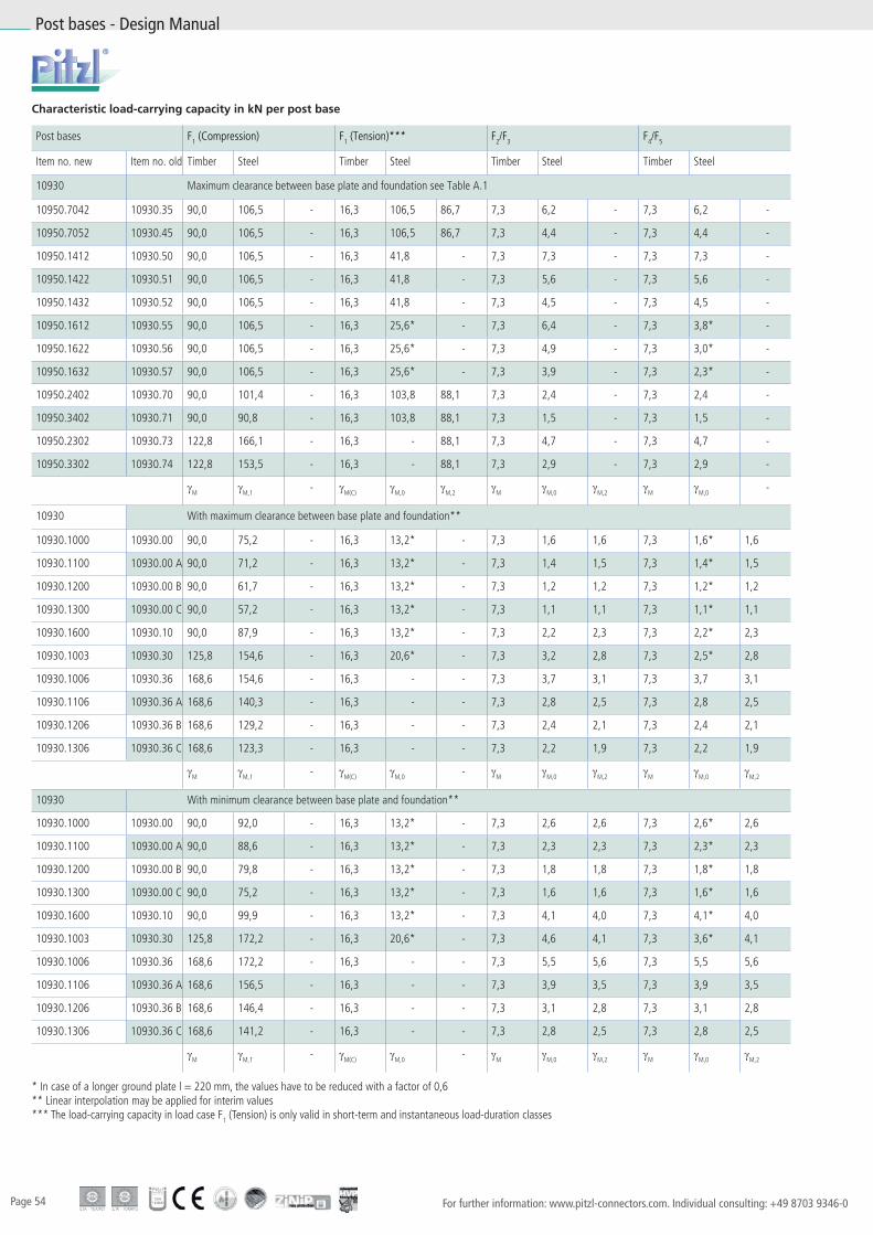
For further information: www.pitzl-connectors.com. Individual consulting: +49 8703 9346-0Page 54
Post bases - Design Manual
Characteristic load-carrying capacity in kN per post base
Post bases F1 (Compression) F1 (Tension)*** F2/F3 F4/F5
Item no. new Item no. old Timber Steel Timber Steel Timber Steel Timber Steel
10930 Maximum clearance between base plate and foundation see Table A.1
10950.7042 10930.35 90,0 106,5 - 16,3 106,5 86,7 7,3 6,2 - 7,3 6,2 -
10950.7052 10930.45 90,0 106,5 - 16,3 106,5 86,7 7,3 4,4 - 7,3 4,4 -
10950.1412 10930.50 90,0 106,5 - 16,3 41,8 - 7,3 7,3 - 7,3 7,3 -
10950.1422 10930.51 90,0 106,5 - 16,3 41,8 - 7,3 5,6 - 7,3 5,6 -
10950.1432 10930.52 90,0 106,5 - 16,3 41,8 - 7,3 4,5 - 7,3 4,5 -
10950.1612 10930.55 90,0 106,5 - 16,3 25,6* - 7,3 6,4 - 7,3 3,8* -
10950.1622 10930.56 90,0 106,5 - 16,3 25,6* - 7,3 4,9 - 7,3 3,0* -
10950.1632 10930.57 90,0 106,5 - 16,3 25,6* - 7,3 3,9 - 7,3 2,3* -
10950.2402 10930.70 90,0 101,4 - 16,3 103,8 88,1 7,3 2,4 - 7,3 2,4 -
10950.3402 10930.71 90,0 90,8 - 16,3 103,8 88,1 7,3 1,5 - 7,3 1,5 -
10950.2302 10930.73 122,8 166,1 - 16,3 - 88,1 7,3 4,7 - 7,3 4,7 -
10950.3302 10930.74 122,8 153,5 - 16,3 - 88,1 7,3 2,9 - 7,3 2,9 -
gM gM,1 - gM(C) gM,0 gM,2 gM gM,0 gM,2 gM gM,0 -
10930 With maximum clearance between base plate and foundation**
10930.1000 10930.00 90,0 75,2 - 16,3 13,2* - 7,3 1,6 1,6 7,3 1,6* 1,6
10930.1100 10930.00 A 90,0 71,2 - 16,3 13,2* - 7,3 1,4 1,5 7,3 1,4* 1,5
10930.1200 10930.00 B 90,0 61,7 - 16,3 13,2* - 7,3 1,2 1,2 7,3 1,2* 1,2
10930.1300 10930.00 C 90,0 57,2 - 16,3 13,2* - 7,3 1,1 1,1 7,3 1,1* 1,1
10930.1600 10930.10 90,0 87,9 - 16,3 13,2* - 7,3 2,2 2,3 7,3 2,2* 2,3
10930.1003 10930.30 125,8 154,6 - 16,3 20,6* - 7,3 3,2 2,8 7,3 2,5* 2,8
10930.1006 10930.36 168,6 154,6 - 16,3 - - 7,3 3,7 3,1 7,3 3,7 3,1
10930.1106 10930.36 A 168,6 140,3 - 16,3 - - 7,3 2,8 2,5 7,3 2,8 2,5
10930.1206 10930.36 B 168,6 129,2 - 16,3 - - 7,3 2,4 2,1 7,3 2,4 2,1
10930.1306 10930.36 C 168,6 123,3 - 16,3 - - 7,3 2,2 1,9 7,3 2,2 1,9
gM gM,1 - gM(C) gM,0 - gM gM,0 gM,2 gM gM,0 gM,2
10930 With minimum clearance between base plate and foundation**
10930.1000 10930.00 90,0 92,0 - 16,3 13,2* - 7,3 2,6 2,6 7,3 2,6* 2,6
10930.1100 10930.00 A 90,0 88,6 - 16,3 13,2* - 7,3 2,3 2,3 7,3 2,3* 2,3
10930.1200 10930.00 B 90,0 79,8 - 16,3 13,2* - 7,3 1,8 1,8 7,3 1,8* 1,8
10930.1300 10930.00 C 90,0 75,2 - 16,3 13,2* - 7,3 1,6 1,6 7,3 1,6* 1,6
10930.1600 10930.10 90,0 99,9 - 16,3 13,2* - 7,3 4,1 4,0 7,3 4,1* 4,0
10930.1003 10930.30 125,8 172,2 - 16,3 20,6* - 7,3 4,6 4,1 7,3 3,6* 4,1
10930.1006 10930.36 168,6 172,2 - 16,3 - - 7,3 5,5 5,6 7,3 5,5 5,6
10930.1106 10930.36 A 168,6 156,5 - 16,3 - - 7,3 3,9 3,5 7,3 3,9 3,5
10930.1206 10930.36 B 168,6 146,4 - 16,3 - - 7,3 3,1 2,8 7,3 3,1 2,8
10930.1306 10930.36 C 168,6 141,2 - 16,3 - - 7,3 2,8 2,5 7,3 2,8 2,5
gM gM,1 - gM(C) gM,0 - gM gM,0 gM,2 gM gM,0 gM,2
* In case of a longer ground plate l = 220 mm, the values have to be reduced with a factor of 0,6 ** Linear interpolation may be applied for interim values *** The load-carrying capacity in load case F1 (Tension) is only valid in short-term and instantaneous load-duration classes
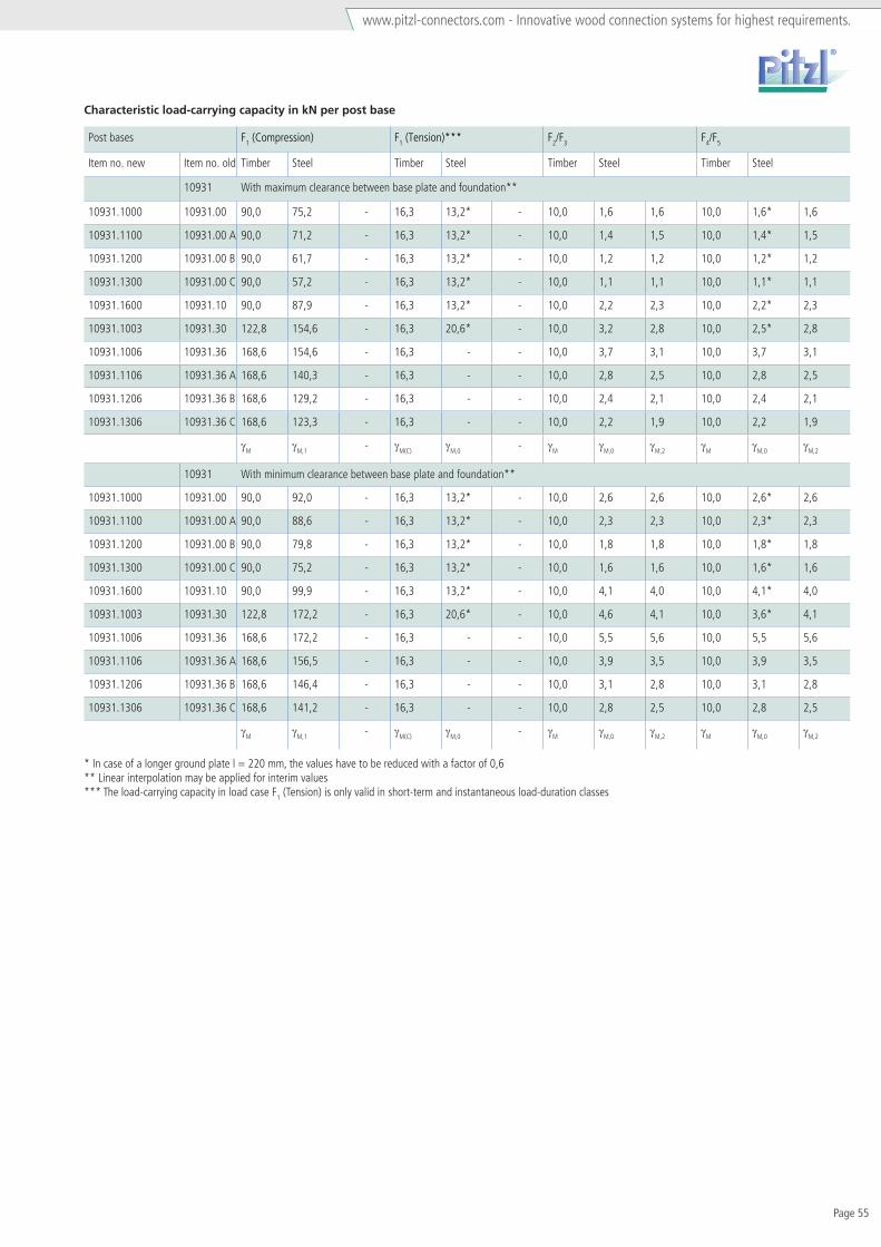
Page 55
www.pitzl-connectors.com - Innovative wood connection systems for highest requirements.
Characteristic load-carrying capacity in kN per post base
Post bases F1 (Compression) F1 (Tension)*** F2/F3 F4/F5
Item no. new Item no. old Timber Steel Timber Steel Timber Steel Timber Steel
10931 With maximum clearance between base plate and foundation**
10931.1000 10931.00 90,0 75,2 - 16,3 13,2* - 10,0 1,6 1,6 10,0 1,6* 1,6
10931.1100 10931.00 A 90,0 71,2 - 16,3 13,2* - 10,0 1,4 1,5 10,0 1,4* 1,5
10931.1200 10931.00 B 90,0 61,7 - 16,3 13,2* - 10,0 1,2 1,2 10,0 1,2* 1,2
10931.1300 10931.00 C 90,0 57,2 - 16,3 13,2* - 10,0 1,1 1,1 10,0 1,1* 1,1
10931.1600 10931.10 90,0 87,9 - 16,3 13,2* - 10,0 2,2 2,3 10,0 2,2* 2,3
10931.1003 10931.30 122,8 154,6 - 16,3 20,6* - 10,0 3,2 2,8 10,0 2,5* 2,8
10931.1006 10931.36 168,6 154,6 - 16,3 - - 10,0 3,7 3,1 10,0 3,7 3,1
10931.1106 10931.36 A 168,6 140,3 - 16,3 - - 10,0 2,8 2,5 10,0 2,8 2,5
10931.1206 10931.36 B 168,6 129,2 - 16,3 - - 10,0 2,4 2,1 10,0 2,4 2,1
10931.1306 10931.36 C 168,6 123,3 - 16,3 - - 10,0 2,2 1,9 10,0 2,2 1,9
gM gM,1 - gM(C) gM,0 - gM gM,0 gM,2 gM gM,0 gM,2
10931 With minimum clearance between base plate and foundation**
10931.1000 10931.00 90,0 92,0 - 16,3 13,2* - 10,0 2,6 2,6 10,0 2,6* 2,6
10931.1100 10931.00 A 90,0 88,6 - 16,3 13,2* - 10,0 2,3 2,3 10,0 2,3* 2,3
10931.1200 10931.00 B 90,0 79,8 - 16,3 13,2* - 10,0 1,8 1,8 10,0 1,8* 1,8
10931.1300 10931.00 C 90,0 75,2 - 16,3 13,2* - 10,0 1,6 1,6 10,0 1,6* 1,6
10931.1600 10931.10 90,0 99,9 - 16,3 13,2* - 10,0 4,1 4,0 10,0 4,1* 4,0
10931.1003 10931.30 122,8 172,2 - 16,3 20,6* - 10,0 4,6 4,1 10,0 3,6* 4,1
10931.1006 10931.36 168,6 172,2 - 16,3 - - 10,0 5,5 5,6 10,0 5,5 5,6
10931.1106 10931.36 A 168,6 156,5 - 16,3 - - 10,0 3,9 3,5 10,0 3,9 3,5
10931.1206 10931.36 B 168,6 146,4 - 16,3 - - 10,0 3,1 2,8 10,0 3,1 2,8
10931.1306 10931.36 C 168,6 141,2 - 16,3 - - 10,0 2,8 2,5 10,0 2,8 2,5
gM gM,1 - gM(C) gM,0 - gM gM,0 gM,2 gM gM,0 gM,2
* In case of a longer ground plate l = 220 mm, the values have to be reduced with a factor of 0,6 ** Linear interpolation may be applied for interim values *** The load-carrying capacity in load case F1 (Tension) is only valid in short-term and instantaneous load-duration classes
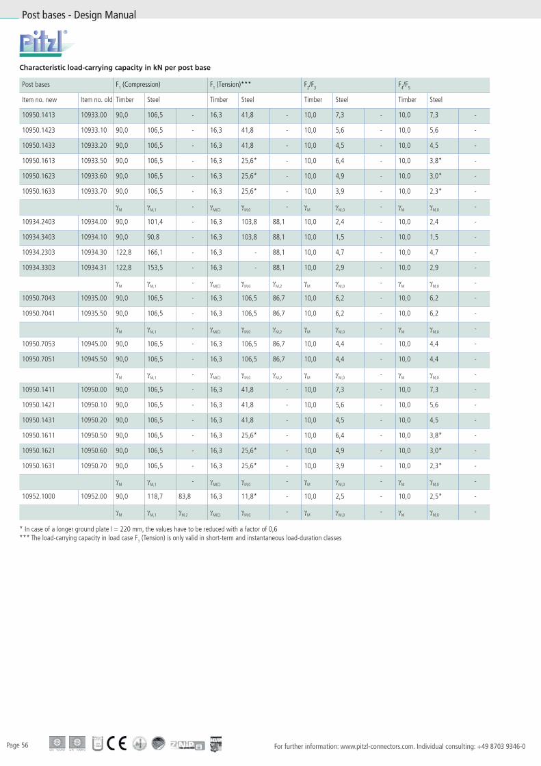
For further information: www.pitzl-connectors.com. Individual consulting: +49 8703 9346-0Page 56
Post bases - Design Manual
Characteristic load-carrying capacity in kN per post base
Post bases F1 (Compression) F1 (Tension)*** F2/F3 F4/F5
Item no. new Item no. old Timber Steel Timber Steel Timber Steel Timber Steel
10950.1413 10933.00 90,0 106,5 - 16,3 41,8 - 10,0 7,3 - 10,0 7,3 -
10950.1423 10933.10 90,0 106,5 - 16,3 41,8 - 10,0 5,6 - 10,0 5,6 -
10950.1433 10933.20 90,0 106,5 - 16,3 41,8 - 10,0 4,5 - 10,0 4,5 -
10950.1613 10933.50 90,0 106,5 - 16,3 25,6* - 10,0 6,4 - 10,0 3,8* -
10950.1623 10933.60 90,0 106,5 - 16,3 25,6* - 10,0 4,9 - 10,0 3,0* -
10950.1633 10933.70 90,0 106,5 - 16,3 25,6* - 10,0 3,9 - 10,0 2,3* -
gM gM,1 - gM(C) gM,0 - gM gM,0 - gM gM,0 -
10934.2403 10934.00 90,0 101,4 - 16,3 103,8 88,1 10,0 2,4 - 10,0 2,4 -
10934.3403 10934.10 90,0 90,8 - 16,3 103,8 88,1 10,0 1,5 - 10,0 1,5 -
10934.2303 10934.30 122,8 166,1 - 16,3 - 88,1 10,0 4,7 - 10,0 4,7 -
10934.3303 10934.31 122,8 153,5 - 16,3 - 88,1 10,0 2,9 - 10,0 2,9 -
gM gM,1 - gM(C) gM,0 gM,2 gM gM,0 - gM gM,0 -
10950.7043 10935.00 90,0 106,5 - 16,3 106,5 86,7 10,0 6,2 - 10,0 6,2 -
10950.7041 10935.50 90,0 106,5 - 16,3 106,5 86,7 10,0 6,2 - 10,0 6,2 -
gM gM,1 - gM(C) gM,0 gM,2 gM gM,0 - gM gM,0 -
10950.7053 10945.00 90,0 106,5 - 16,3 106,5 86,7 10,0 4,4 - 10,0 4,4 -
10950.7051 10945.50 90,0 106,5 - 16,3 106,5 86,7 10,0 4,4 - 10,0 4,4 -
gM gM,1 - gM(C) gM,0 gM,2 gM gM,0 - gM gM,0 -
10950.1411 10950.00 90,0 106,5 - 16,3 41,8 - 10,0 7,3 - 10,0 7,3 -
10950.1421 10950.10 90,0 106,5 - 16,3 41,8 - 10,0 5,6 - 10,0 5,6 -
10950.1431 10950.20 90,0 106,5 - 16,3 41,8 - 10,0 4,5 - 10,0 4,5 -
10950.1611 10950.50 90,0 106,5 - 16,3 25,6* - 10,0 6,4 - 10,0 3,8* -
10950.1621 10950.60 90,0 106,5 - 16,3 25,6* - 10,0 4,9 - 10,0 3,0* -
10950.1631 10950.70 90,0 106,5 - 16,3 25,6* - 10,0 3,9 - 10,0 2,3* -
gM gM,1 - gM(C) gM,0 - gM gM,0 - gM gM,0 -
10952.1000 10952.00 90,0 118,7 83,8 16,3 11,8* - 10,0 2,5 - 10,0 2,5* -
gM gM,1 gM,2 gM(C) gM,0 - gM gM,0 - gM gM,0 -
* In case of a longer ground plate l = 220 mm, the values have to be reduced with a factor of 0,6 *** The load-carrying capacity in load case F1 (Tension) is only valid in short-term and instantaneous load-duration classes
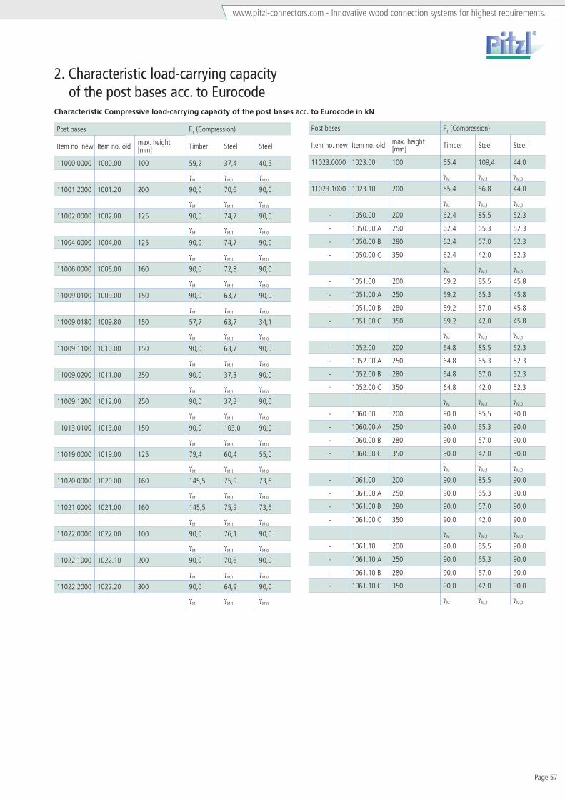
Page 57
www.pitzl-connectors.com - Innovative wood connection systems for highest requirements.
2. Characteristic load-carrying capacity of the post bases acc. to EurocodeCharacteristic Compressive load-carrying capacity of the post bases acc. to Eurocode in kN
Post bases F1 (Compression)
Item no. new Item no. old max. height [mm] Timber Steel Steel
11000.0000 1000.00 100 59,2 37,4 40,5
gM gM,1 gM,0
11001.2000 1001.20 200 90,0 70,6 90,0
gM gM,1 gM,0
11002.0000 1002.00 125 90,0 74,7 90,0
gM gM,1 gM,0
11004.0000 1004.00 125 90,0 74,7 90,0
gM gM,1 gM,0
11006.0000 1006.00 160 90,0 72,8 90,0
gM gM,1 gM,0
11009.0100 1009.00 150 90,0 63,7 90,0
gM gM,1 gM,0
11009.0180 1009.80 150 57,7 63,7 34,1
gM gM,1 gM,0
11009.1100 1010.00 150 90,0 63,7 90,0
gM gM,1 gM,0
11009.0200 1011.00 250 90,0 37,3 90,0
gM gM,1 gM,0
11009.1200 1012.00 250 90,0 37,3 90,0
gM gM,1 gM,0
11013.0100 1013.00 150 90,0 103,0 90,0
gM gM,1 gM,0
11019.0000 1019.00 125 79,4 60,4 55,0
gM gM,1 gM,0
11020.0000 1020.00 160 145,5 75,9 73,6
gM gM,1 gM,0
11021.0000 1021.00 160 145,5 75,9 73,6
gM gM,1 gM,0
11022.0000 1022.00 100 90,0 76,1 90,0
gM gM,1 gM,0
11022.1000 1022.10 200 90,0 70,6 90,0
gM gM,1 gM,0
11022.2000 1022.20 300 90,0 64,9 90,0
gM gM,1 gM,0
Post bases F1 (Compression)
Item no. new Item no. old max. height [mm] Timber Steel Steel
11023.0000 1023.00 100 55,4 109,4 44,0
gM gM,1 gM,0
11023.1000 1023.10 200 55,4 56,8 44,0
gM gM,1 gM,0
- 1050.00 200 62,4 85,5 52,3
- 1050.00 A 250 62,4 65,3 52,3
- 1050.00 B 280 62,4 57,0 52,3
- 1050.00 C 350 62,4 42,0 52,3
gM gM,1 gM,0
- 1051.00 200 59,2 85,5 45,8
- 1051.00 A 250 59,2 65,3 45,8
- 1051.00 B 280 59,2 57,0 45,8
- 1051.00 C 350 59,2 42,0 45,8
gM gM,1 gM,0
- 1052.00 200 64,8 85,5 52,3
- 1052.00 A 250 64,8 65,3 52,3
- 1052.00 B 280 64,8 57,0 52,3
- 1052.00 C 350 64,8 42,0 52,3
gM gM,1 gM,0
- 1060.00 200 90,0 85,5 90,0
- 1060.00 A 250 90,0 65,3 90,0
- 1060.00 B 280 90,0 57,0 90,0
- 1060.00 C 350 90,0 42,0 90,0
gM gM,1 gM,0
- 1061.00 200 90,0 85,5 90,0
- 1061.00 A 250 90,0 65,3 90,0
- 1061.00 B 280 90,0 57,0 90,0
- 1061.00 C 350 90,0 42,0 90,0
gM gM,1 gM,0
- 1061.10 200 90,0 85,5 90,0
- 1061.10 A 250 90,0 65,3 90,0
- 1061.10 B 280 90,0 57,0 90,0
- 1061.10 C 350 90,0 42,0 90,0
gM gM,1 gM,0
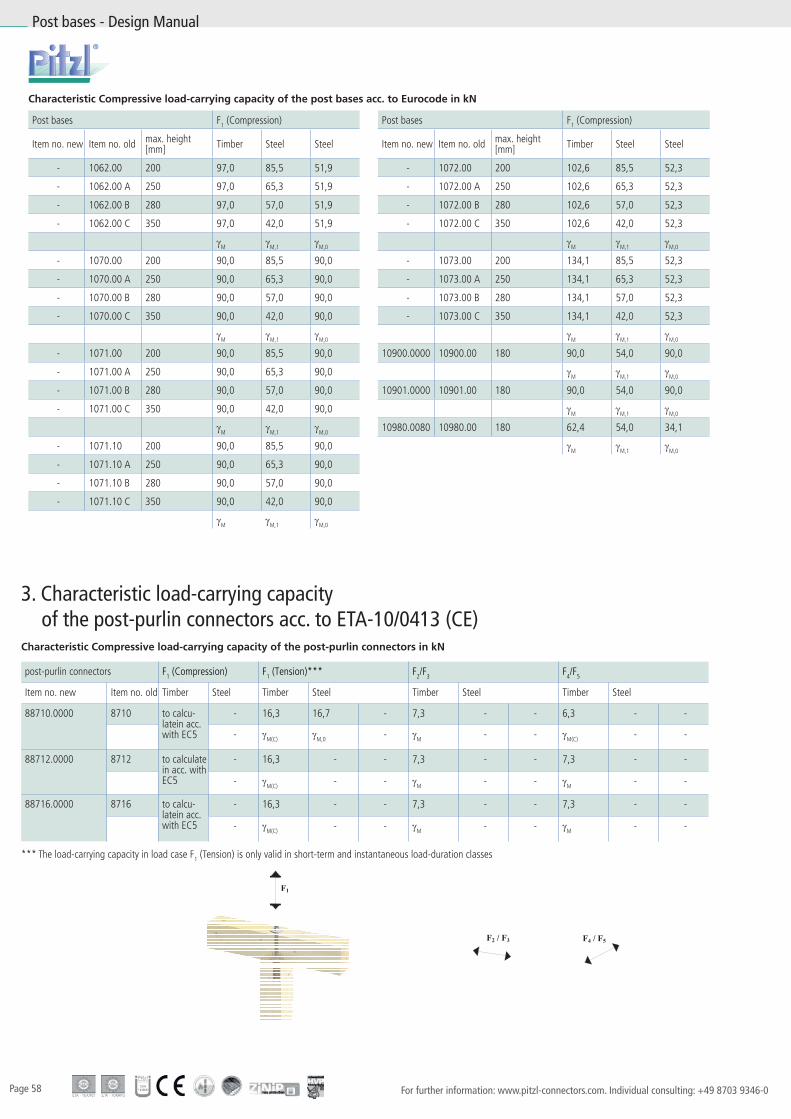
For further information: www.pitzl-connectors.com. Individual consulting: +49 8703 9346-0Page 58
Post bases - Design Manual
Post bases F1 (Compression)
Item no. new Item no. old max. height [mm] Timber Steel Steel
- 1062.00 200 97,0 85,5 51,9
- 1062.00 A 250 97,0 65,3 51,9
- 1062.00 B 280 97,0 57,0 51,9
- 1062.00 C 350 97,0 42,0 51,9
gM gM,1 gM,0
- 1070.00 200 90,0 85,5 90,0
- 1070.00 A 250 90,0 65,3 90,0
- 1070.00 B 280 90,0 57,0 90,0
- 1070.00 C 350 90,0 42,0 90,0
gM gM,1 gM,0
- 1071.00 200 90,0 85,5 90,0
- 1071.00 A 250 90,0 65,3 90,0
- 1071.00 B 280 90,0 57,0 90,0
- 1071.00 C 350 90,0 42,0 90,0
gM gM,1 gM,0
- 1071.10 200 90,0 85,5 90,0
- 1071.10 A 250 90,0 65,3 90,0
- 1071.10 B 280 90,0 57,0 90,0
- 1071.10 C 350 90,0 42,0 90,0
gM gM,1 gM,0
Post bases F1 (Compression)
Item no. new Item no. old max. height [mm] Timber Steel Steel
- 1072.00 200 102,6 85,5 52,3
- 1072.00 A 250 102,6 65,3 52,3
- 1072.00 B 280 102,6 57,0 52,3
- 1072.00 C 350 102,6 42,0 52,3
gM gM,1 gM,0
- 1073.00 200 134,1 85,5 52,3
- 1073.00 A 250 134,1 65,3 52,3
- 1073.00 B 280 134,1 57,0 52,3
- 1073.00 C 350 134,1 42,0 52,3
gM gM,1 gM,0
10900.0000 10900.00 180 90,0 54,0 90,0
gM gM,1 gM,0
10901.0000 10901.00 180 90,0 54,0 90,0
gM gM,1 gM,0
10980.0080 10980.00 180 62,4 54,0 34,1
gM gM,1 gM,0
3. Characteristic load-carrying capacity of the post-purlin connectors acc. to ETA-10/0413 (CE)Characteristic Compressive load-carrying capacity of the post-purlin connectors in kN
post-purlin connectors F1 (Compression) F1 (Tension)*** F2/F3 F4/F5
Item no. new Item no. old Timber Steel Timber Steel Timber Steel Timber Steel
88710.0000 8710 to calcu-latein acc. with EC5
- 16,3 16,7 - 7,3 - - 6,3 - -
- gM(C) gM,0 - gM - - gM(C) - -
88712.0000 8712 to calculate in acc. with EC5
- 16,3 - - 7,3 - - 7,3 - -
- gM(C) - - gM - - gM - -
88716.0000 8716 to calcu-latein acc. with EC5
- 16,3 - - 7,3 - - 7,3 - -
- gM(C) - - gM - - gM - -
*** The load-carrying capacity in load case F1 (Tension) is only valid in short-term and instantaneous load-duration classes
Characteristic Compressive load-carrying capacity of the post bases acc. to Eurocode in kN
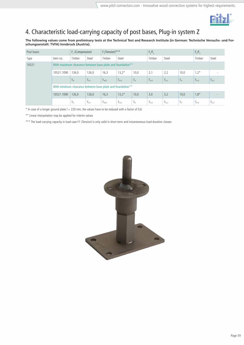
Page 59
www.pitzl-connectors.com - Innovative wood connection systems for highest requirements.
4. Characteristic load-carrying capacity of post bases, Plug-in system ZThe following values come from preliminary tests at the Technical Test and Research Institute (in German: Technische Versuchs- und For-schungsanstalt: TVFA) Innsbruck (Austria).
Post bases F1 (Compression) F1(Tension)*** F2/F3 F4/F5
Type Item no. Timber Steel Timber Steel Timber Steel Timber Steel
10521 With maximum clearance between base plate and foundation**
10521.1090 126,0 126,0 16,3 13,2* 10,0 2,1 2,2 10,0 1,2* -
gm gm,1 gm(C) gm,0 gm gm,0 gm,2 gm gm,0 gm,2
With minimum clearance between base plate and foundation**
10521.1090 126,0 126,0 16,3 13,2* 10,0 3,0 3,2 10,0 1,8* -
gm gm,1 gm(C) gm,0 gm gm,0 gm,2 gm gm,0 gm,2
* In case of a longer ground plate l = 220 mm, the values have to be reduced with a factor of 0,6
** Linear interpolation may be applied for interim values
*** The load-carrying capacity in load case F1 (Tension) is only valid in short-term and instantaneous load-duration classes
We recommend our distributor:
PitzlMetallbauGmbH & Co. KG
DIN18800
Fast, simple and precise: for the best result
• Wood connectors• Post bases• Balcony posts / fence posts• Tools / accessories• always up to date with www.pitzl-connectors.com
Manufacturer:
Pitzl Metallbau GmbH & Co. KGSiemensstraße 26
84051 Altheim - Germany
Tel.: +49 8703 9346-0
Telefax: +49 8703 9346-55
Email: [email protected]
www.pitzl-connectors.com
For more information and technical details, downloads and helpful video tutorials: www.pitzl-connectors.com.Alternatively, our competent staff are always available for advice: +49 8703 9346-0.
All r
ight
s re
serv
ed. R
eprin
t in
part
or w
hole
onl
y w
ith e
xpre
ss p
erm
issio
n of
Pitz
l Met
allb
au G
mbH
. Mod
ifica
tions
and
erro
rs re
serv
ed. I
mag
es a
re s
imila
r. Ver
sion
as o
f 06
/201
5, v
500/
dd-G
BR-4
2-1