Embed Size (px)
Citation preview
AME4283/5283Concurrent Design and Manufacturing
Design Lesson 1: Introduction to e -Design
(Review Chapter 1)
Kuang-Hua Chang, ProfessorSchool of Aerospace and Mechanical Engineering
The University of OklahomaNorman, OK
January 18, 2017
Design Lesson 1: Introd. to e-Design
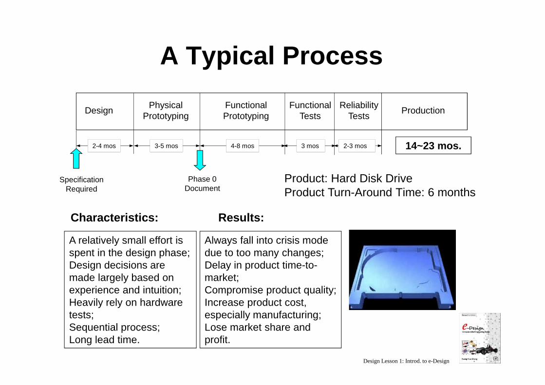
A Typical Process
2-4 mos 3-5 mos
Specification Required
PhysicalPrototyping
FunctionalPrototyping
4-8 mos 3 mos 2-3 mos
FunctionalTests
ReliabilityTests
Production
Phase 0Document
14~23 mos.
Design
A relatively small effort is spent in the design phase;Design decisions are made largely based on experience and intuition;Heavily rely on hardware tests;Sequential process;Long lead time.
Characteristics:
Always fall into crisis mode due to too many changes;Delay in product time-to-market;Compromise product quality;Increase product cost, especially manufacturing;Lose market share and profit.
Results:
Product: Hard Disk DriveProduct Turn-Around Time: 6 months
Design Lesson 1: Introd. to e-Design
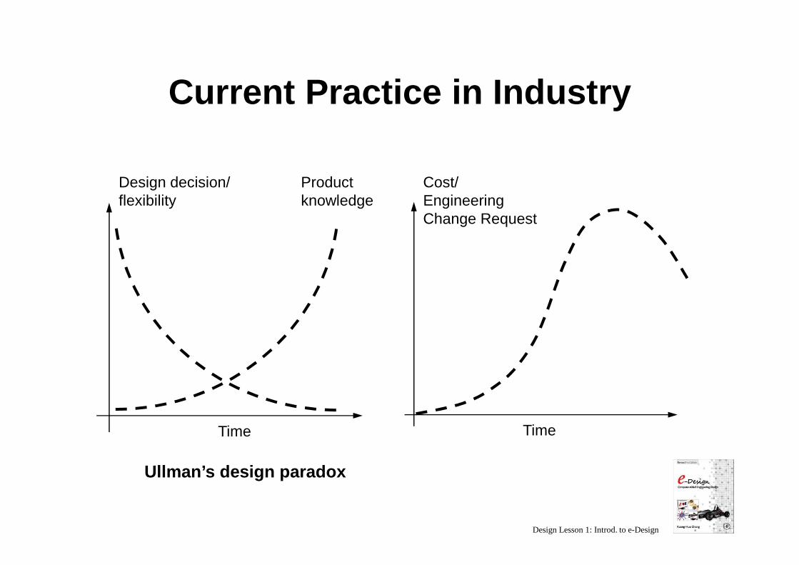
Current Practice in Industry
Product knowledge
Time
Design decision/flexibility
Cost/Engineering Change Request
Time
Ullman’s design paradox
Design Lesson 1: Introd. to e-Design
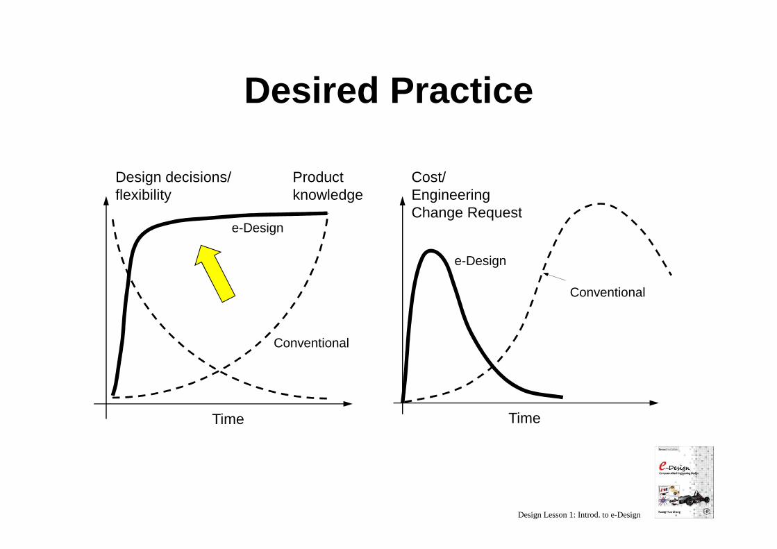
Desired Practice
e-Design
Product knowledge
Time
Design decisions/flexibility
Cost/Engineering Change Request
Time
Conventional
Conventional
e-Design
Design Lesson 1: Introd. to e-Design
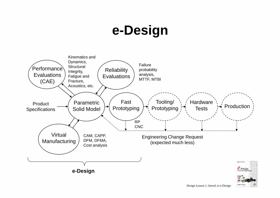
e-Design
Parametric Solid Model
Performance Evaluations
(CAE)
Kinematics and Dynamics,Structural Integrity,Fatigue and Fracture,Acoustics, etc.
Failure probability analysis,MTTF, MTBI
Virtual Manufacturing
Reliability Evaluations
Fast Prototyping
Hardware Tests Production
Engineering Change Request (expected much less)
e-Design
Product Specifications
Tooling/ Prototyping
CAM, CAPP, DFM, DFMA, Cost analysis
RPCNC
Design Lesson 1: Introd. to e-Design
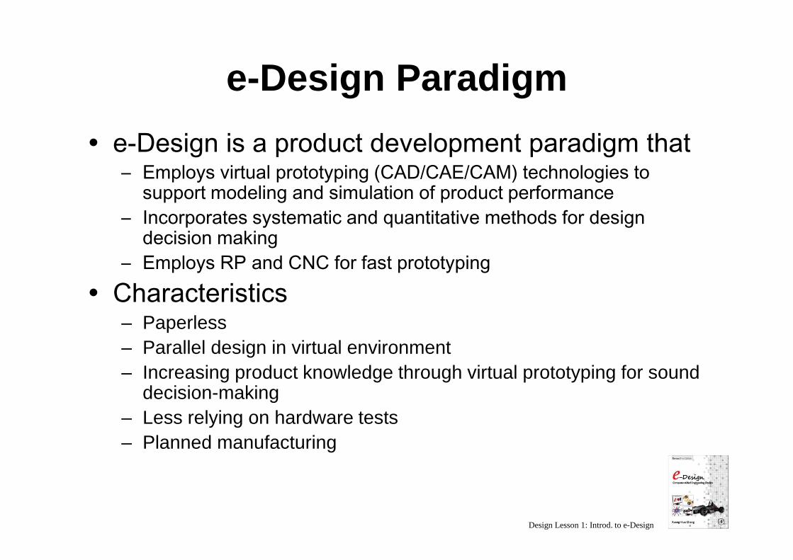
e-Design Paradigm
� e-Design is a product development paradigm that– Employs virtual prototyping (CAD/CAE/CAM) technologies to
support modeling and simulation of product performance– Incorporates systematic and quantitative methods for design
decision making– Employs RP and CNC for fast prototyping
� Characteristics– Paperless– Parallel design in virtual environment– Increasing product knowledge through virtual prototyping for sound
decision-making– Less relying on hardware tests– Planned manufacturing
Design Lesson 1: Introd. to e-Design
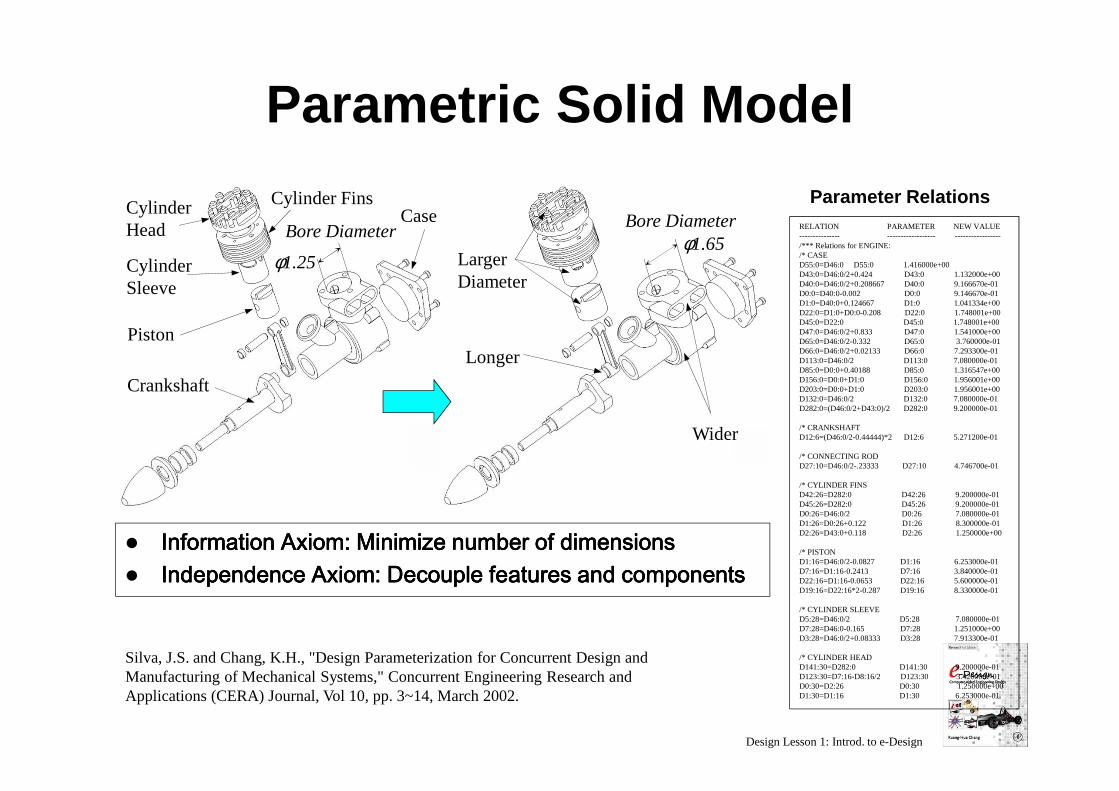
Silva, J.S. and Chang, K.H., "Design Parameterization for Concurrent Design and Manufacturing of Mechanical Systems," Concurrent Engineering Research and Applications (CERA) Journal, Vol 10, pp. 3~14, March 2002.
Parametric Solid Model
RELATION PARAMETER NEW VALUE--------------- ------------------ -----------------/*** Relations for ENGINE:/* CASED55:0=D46:0 D55:0 1.416000e+00 D43:0=D46:0/2+0.424 D43:0 1.132000e+00 D40:0=D46:0/2+0.208667 D40:0 9.166670e-01 D0:0=D40:0-0.002 D0:0 9.146670e-01 D1:0=D40:0+0.124667 D1:0 1.041334e+00 D22:0=D1:0+D0:0-0.208 D22:0 1.748001e+00 D45:0=D22:0 D45:0 1.748001e+00 D47:0=D46:0/2+0.833 D47:0 1.541000e+00 D65:0=D46:0/2-0.332 D65:0 3.760000e-01 D66:0=D46:0/2+0.02133 D66:0 7.293300e-01 D113:0=D46:0/2 D113:0 7.080000e-01 D85:0=D0:0+0.40188 D85:0 1.316547e+00 D156:0=D0:0+D1:0 D156:0 1.956001e+00 D203:0=D0:0+D1:0 D203:0 1.956001e+00 D132:0=D46:0/2 D132:0 7.080000e-01 D282:0=(D46:0/2+D43:0)/2 D282:0 9.200000e-01
/* CRANKSHAFTD12:6=(D46:0/2-0.44444)*2 D12:6 5.271200e-01
/* CONNECTING RODD27:10=D46:0/2-.23333 D27:10 4.746700e-01
/* CYLINDER FINSD42:26=D282:0 D42:26 9.200000e-01 D45:26=D282:0 D45:26 9.200000e-01 D0:26=D46:0/2 D0:26 7.080000e-01 D1:26=D0:26+0.122 D1:26 8.300000e-01 D2:26=D43:0+0.118 D2:26 1.250000e+00
/* PISTOND1:16=D46:0/2-0.0827 D1:16 6.253000e-01 D7:16=D1:16-0.2413 D7:16 3.840000e-01 D22:16=D1:16-0.0653 D22:16 5.600000e-01 D19:16=D22:16*2-0.287 D19:16 8.330000e-01
/* CYLINDER SLEEVE D5:28=D46:0/2 D5:28 7.080000e-01 D7:28=D46:0-0.165 D7:28 1.251000e+00 D3:28=D46:0/2+0.08333 D3:28 7.913300e-01
/* CYLINDER HEADD141:30=D282:0 D141:30 9.200000e-01 D123:30=D7:16-D8:16/2 D123:30 3.420000e-01 D0:30=D2:26 D0:30 1.250000e+00 D1:30=D1:16 D1:30 6.253000e-01
� Information Axiom: Minimize number of dimensionsInformation Axiom: Minimize number of dimensionsInformation Axiom: Minimize number of dimensionsInformation Axiom: Minimize number of dimensions� Independence Axiom: Decouple features and componentsIndependence Axiom: Decouple features and componentsIndependence Axiom: Decouple features and componentsIndependence Axiom: Decouple features and components
Parameter RelationsCaseCylinder
Head
Piston
Cylinder Sleeve
Cylinder Fins
Bore Diameter
Crankshaft
φ1.25 Larger Diameter
Bore Diameter
Longer
Wider
φ1.65
Design Lesson 1: Introd. to e-Design
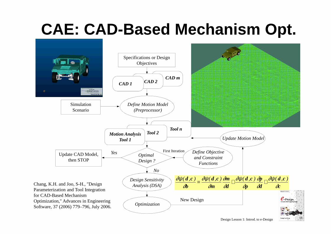
CAE: CAD -Based Mechanism Opt.
Tool n
CAD mCAD 2
Specifications or Design Objectives
Optimization
Update CAD Model, then STOP
Yes
No
New Design
CAD 1
Simulation Scenario
Design Sensitivity Analysis (DSA)
Tool 2Motion Analysis Tool 1
Define Motion Model(Preprocessor)
Update Motion Model
Define Objective and Constraint
Functions
OptimalDesign ?
First Iteration
Chang, K.H. and Joo, S-H., "Design Parameterization and Tool Integration for CAD-Based Mechanism Optimization," Advances in Engineering Software, 37 (2006) 779–796, July 2006.
ccd
dp
pcd
dm
mcd
bcd
∂∂ψ
∂∂
∂∂ψ
∂∂
∂∂ψ
∂∂ψ ),(),(),(),( ++=
Design Lesson 1: Introd. to e-Design
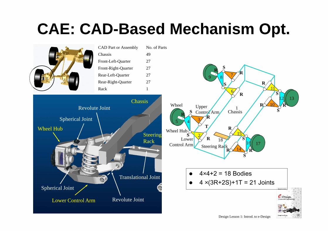
CAE: CAD -Based Mechanism Opt.CAD Part or Assembly No. of Parts
Chassis 49
Front-Left-Quarter 27
Front-Right-Quarter 27
Rear-Left-Quarter 27
Rear-Right-Quarter 27
Rack 1
S
SRR
4
2
3
Wheel Hub
R
5
Wheel Upper Control Arm
LowerControl Arm
S
SRR
8
6
7
R
9
S
SR R
12
11
10
R
13
S
SR R
16
15
14
R
1718
Steering Rack
T
1Chassis
Revolute Joint
Spherical Joint
Revolute JointChassis
Wheel Hub
Lower Control Arm
Translational Joint
Spherical Joint
Steering Rack
� 4×4+2 = 18 Bodies� 4 ×(3R+2S)+1T = 21 Joints
Design Lesson 1: Introd. to e-Design
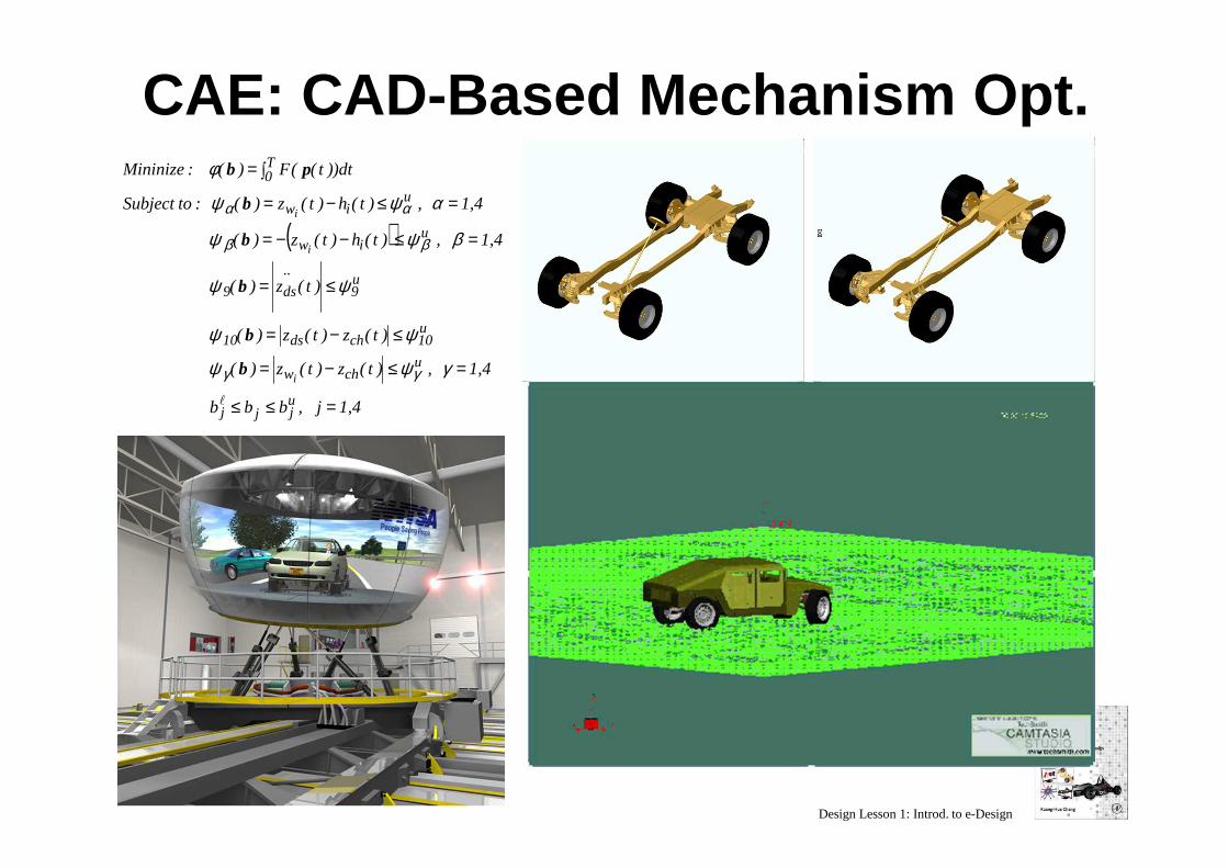
CAE: CAD -Based Mechanism Opt.
( )
1,4j ,bbb
1,4 , )t(z)t(z)(
)t(z)t(z)(
)t(z)(
1,4 , )t(h)t(z)(
1,4 , )t(h)t(z)( :to Subject
dt))t((F)( :Mininize
ujjj
uchw
u10chds10
u9
..
ds9
uiw
uiw
T0
i
i
i
=≤≤
=≤−=
≤−=
≤=
=≤−−=
=≤−=
∫=
l
γψψ
ψψ
ψψ
βψψ
αψψ
φ
γγ
ββ
αα
b
b
b
b
b
pb
Design Lesson 1: Introd. to e-Design
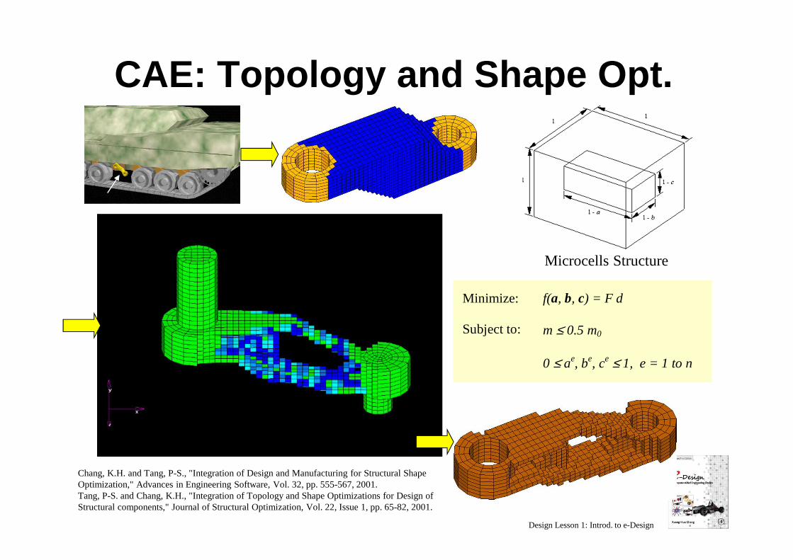
CAE: Topology and Shape Opt.
Roadarm
Microcells Structure
Minimize:
Subject to:
f(a, b, c) = F d
m ≤ 0.5 m0
0 ≤ ae, be, ce ≤ 1, e = 1 to n
Chang, K.H. and Tang, P-S., "Integration of Design and Manufacturing for Structural Shape Optimization," Advances in Engineering Software, Vol. 32, pp. 555-567, 2001. Tang, P-S. and Chang, K.H., "Integration of Topology and Shape Optimizations for Design of Structural components," Journal of Structural Optimization, Vol. 22, Issue 1, pp. 65-82, 2001.
Design Lesson 1: Introd. to e-Design
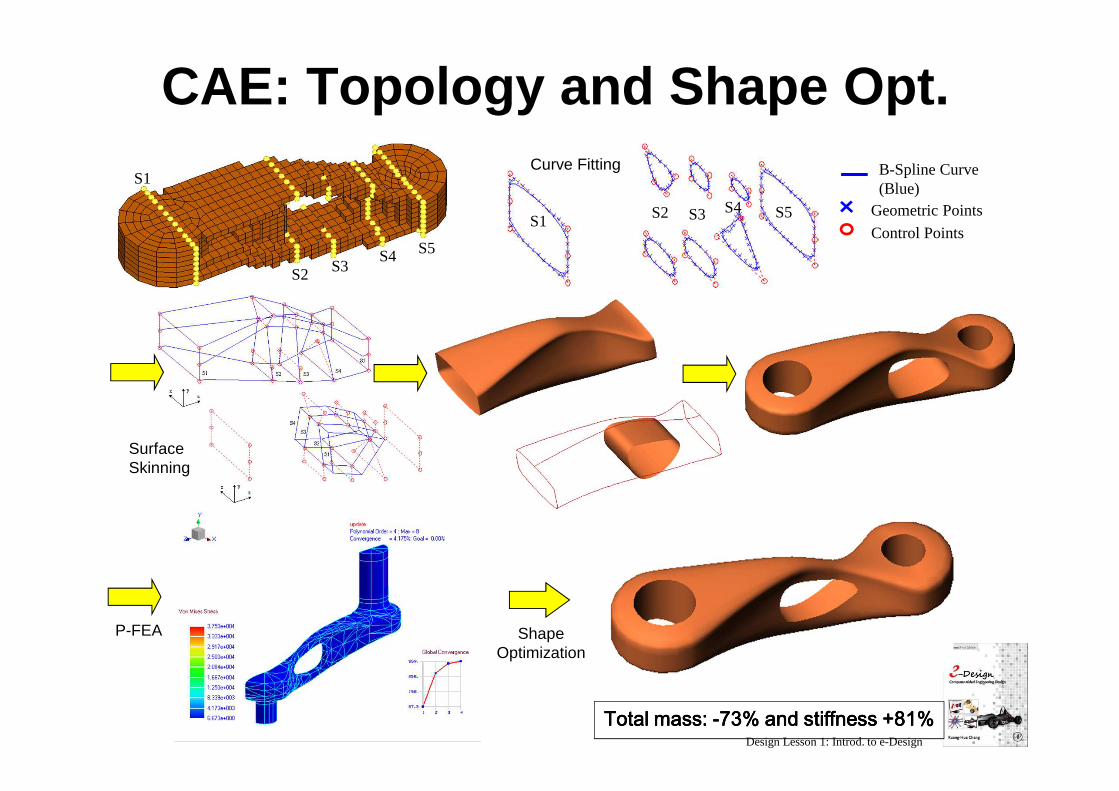
CAE: Topology and Shape Opt.
Total mass: Total mass: Total mass: Total mass: ----73% and stiffness +81%73% and stiffness +81%73% and stiffness +81%73% and stiffness +81%
P-FEA
Control Points
Geometric Points
B-Spline Curve (Blue)
SurfaceSkinning
ShapeOptimization
Curve FittingS1
S2 S3S4 S5
S1 S2 S3 S4 S5
Design Lesson 1: Introd. to e-Design
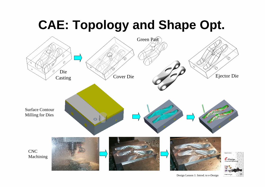
CAE: Topology and Shape Opt.
Cover Die Ejector DieDie
Casting
Surface Contour Milling for Dies
CNC Machining
Green Part
Design Lesson 1: Introd. to e-Design
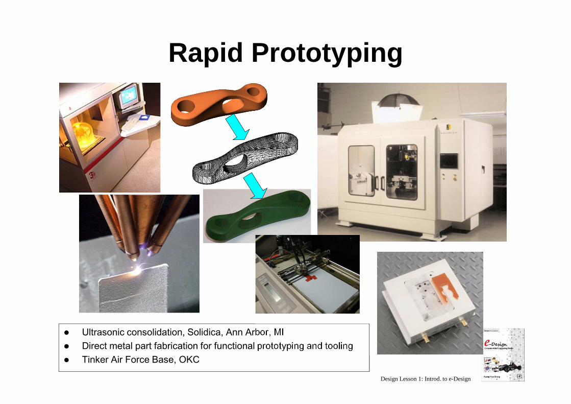
Rapid Prototyping
� Ultrasonic consolidation, Solidica, Ann Arbor, MI� Direct metal part fabrication for functional prototyping and tooling� Tinker Air Force Base, OKC
Design Lesson 1: Introd. to e-Design
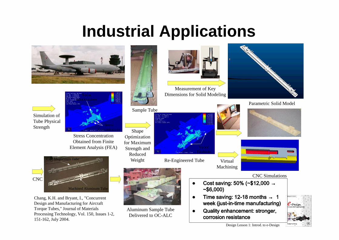
Industrial Applications
� Cost saving: 50% (~$12,000 Cost saving: 50% (~$12,000 Cost saving: 50% (~$12,000 Cost saving: 50% (~$12,000 →→→→~$6,000)~$6,000)~$6,000)~$6,000)
� Time saving: 12Time saving: 12Time saving: 12Time saving: 12----18 months 18 months 18 months 18 months →→→→ 1 1 1 1 week (justweek (justweek (justweek (just----inininin----time manufacturing)time manufacturing)time manufacturing)time manufacturing)
� Quality enhancement: stronger, Quality enhancement: stronger, Quality enhancement: stronger, Quality enhancement: stronger, corrosion resistancecorrosion resistancecorrosion resistancecorrosion resistance
Machined Aluminum Tube
Cast Magnesium Tube
Measurement of Key Dimensions for Solid Modeling
Sample Tube
Stress Concentrations
Stress Concentration
Parametric Solid Model
Simulation of Tube Physical Strength
Stress Concentration Obtained from Finite
Element Analysis (FEA)
Shape Optimization for Maximum Strength and
Reduced Weight Re-Engineered Tube
Varied Thickness
CNC SimulationsCNC
VirtualMachining
Aluminum Sample Tube Delivered to OC-ALC
Chang, K.H. and Bryant, I., "Concurrent Design and Manufacturing for Aircraft Torque Tubes," Journal of Materials Processing Technology, Vol. 150, Issues 1-2, 151-162, July 2004.
Design Lesson 1: Introd. to e-Design
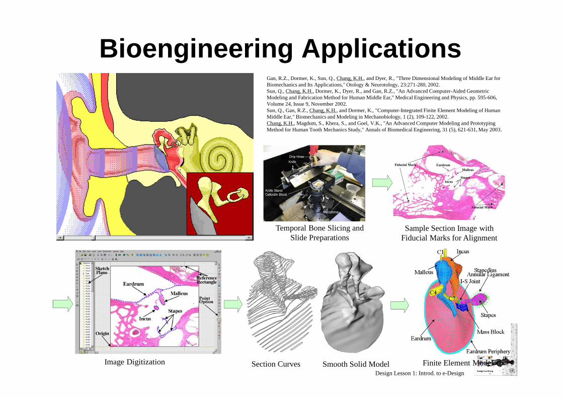
Bioengineering Applications
Temporal Bone Slicing and Slide Preparations
Sample Section Image with Fiducial Marks for Alignment
Image Digitization Section Curves Smooth Solid Model Finite Element Model
Gan, R.Z., Dormer, K., Sun, Q., Chang, K.H., and Dyer, R., "Three Dimensional Modeling of Middle Ear for Biomechanics and Its Applications," Otology & Neurotology, 23:271-280, 2002. Sun, Q., Chang, K.H., Dormer, K., Dyer, R., and Gan, R.Z., "An Advanced Computer-Aided Geometric Modeling and Fabrication Method for Human Middle Ear," Medical Engineering and Physics, pp. 595-606, Volume 24, Issue 9, November 2002. Sun, Q., Gan, R.Z., Chang, K.H., and Dormer, K., "Computer-Integrated Finite Element Modeling of Human Middle Ear," Biomechanics and Modeling in Mechanobiology, 1 (2), 109-122, 2002. Chang, K.H., Magdum, S., Khera, S., and Goel, V.K., "An Advanced Computer Modeling and Prototyping Method for Human Tooth Mechanics Study," Annals of Biomedical Engineering, 31 (5), 621-631, May 2003.
Design Lesson 1: Introd. to e-Design
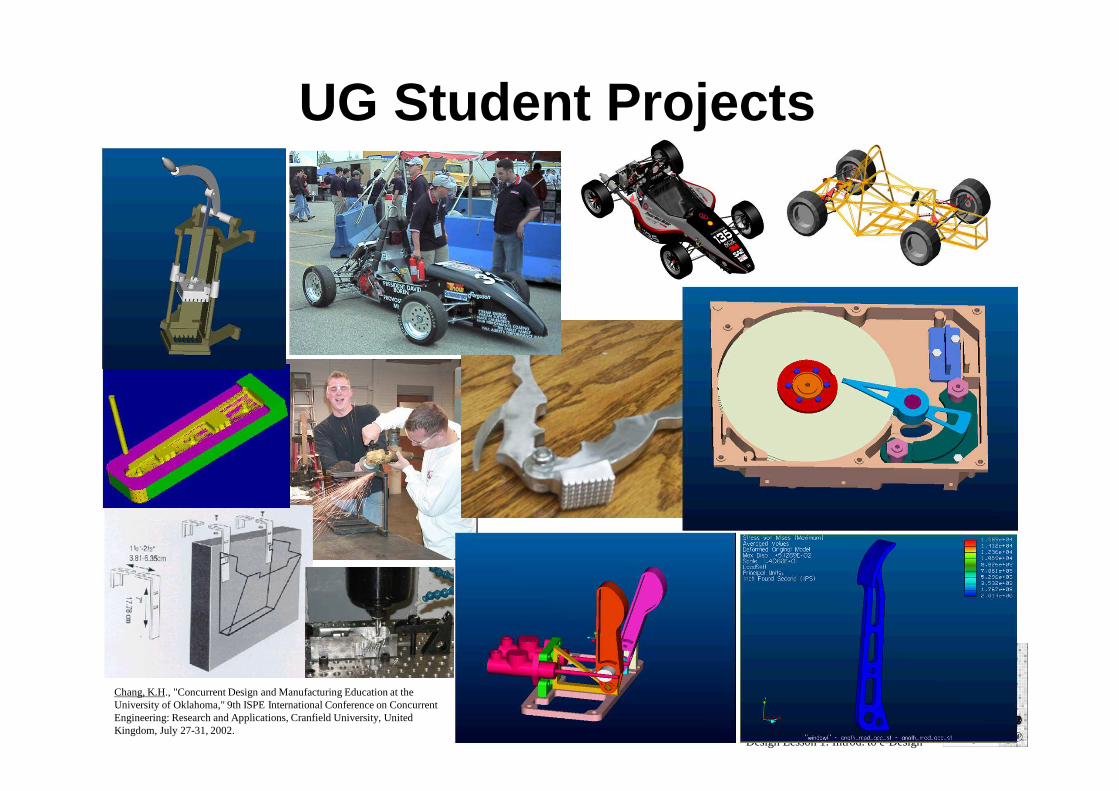
UG Student Projects
Chang, K.H., "Concurrent Design and Manufacturing Education at the University of Oklahoma," 9th ISPE International Conference on Concurrent Engineering: Research and Applications, Cranfield University, United Kingdom, July 27-31, 2002.
Design Lesson 1: Introd. to e-Design
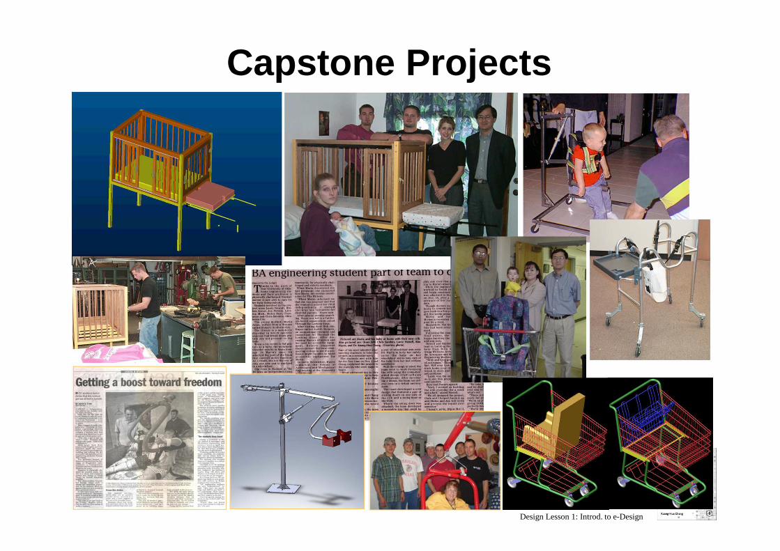
Capstone Projects
Design Lesson 1: Introd. to e-Design
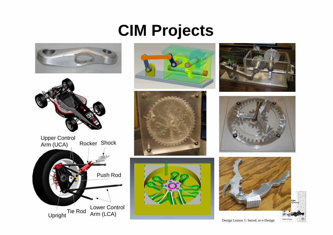
CIM Projects
Rocker Shock
Lower Control Arm (LCA)
Push Rod
Upright
Upper Control Arm (UCA)
Tie Rod
Design Lesson 1: Introd. to e-Design
Practice in Industry
� e-Design has been adopted and practiced by industry; e.g., Boeing 777*, The Big Three**
� CAD/CAE/CAM/RP technology and tools are very popular and widely employed for product development in industry
� All ME students should have some exposure to such technology and tools in order to be competitive in industry
Reading assignments:*Boeing 777: 100% Digitally Designed Using 3D Solids Technology, isites.harvard.edu/fs/docs/icb.topic86897.files/September_29/Boeing_777.pdf** Vasilash, G. S., 1998, Networking the Organization: Ford's CAD/CAM/CAE/PIM Strategy www.autofieldguide.com/articles/networking-the-organization-ford's-cad-cam-cae-pim-strategy


![[Donald E. Kirk] Optimal Control Theory an Introd(Bookos.org)](https://img.pdfslide.us/doc/110x75/552e04b64a7959035a8b484e/donald-e-kirk-optimal-control-theory-an-introdbookosorg.jpg)