Embed Size (px)
Citation preview

Design Investigation Report Cline Avenue Oil Spill Site Gary, Indiana Glenn Springs Holdings (GSH)
GHD | 085886 | Report No 3 | September 19 2017
GHD | Design Investigation Report | 085886 (3) | Page i
Table of Contents
1. Introduction ................................................................................................................................... 1
2. Design Investigation Activity Summary ........................................................................................ 1
2.1 Investigation Area Mapping ............................................................................................... 1
2.1.1 Topographic Mapping ....................................................................................... 1 2.1.2 Utility Clearances/Buried Utility Mapping ......................................................... 2 2.1.3 Geophysical Analysis ....................................................................................... 3
2.2 Investigation Observations................................................................................................. 3
2.3 LNAPL Fingerprint Analysis ............................................................................................... 3
2.3.1 Chemical Property Analysis .............................................................................. 3 2.3.2 Physical Property Analysis ............................................................................... 4
2.4 Groundwater Investigation ................................................................................................. 4
2.4.1 Water/LNAPL Level Monitoring ........................................................................ 4 2.4.2 Surface Water Level Monitoring ....................................................................... 4
2.5 LIF Investigation ................................................................................................................. 5
2.5.1 Methodologies .................................................................................................. 5 2.5.2 Findings ............................................................................................................ 5
3. Conceptual Site Model of LNAPL Transport ................................................................................ 6
4. Conclusions .................................................................................................................................. 6
Figure Index Figure 1.1 Investigation Area Location
Figure 1.2 Investigation Area Plan
Figure 2.1 Base Map
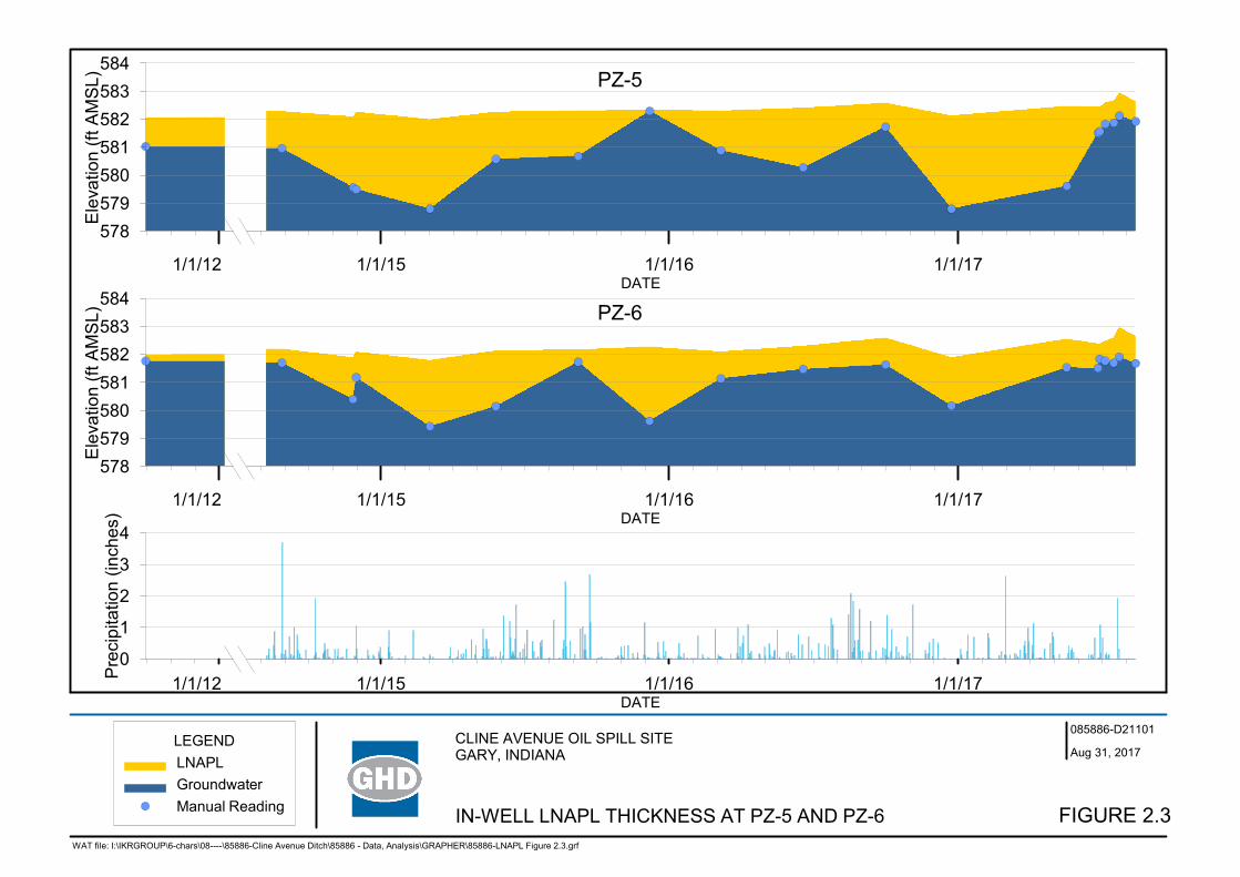
Figure 2.2 In-Well LNAPL Thickness at PZ-3 and PZ-4
Figure 2.3 In-Well LNAPL Thickness at PZ-5 and PZ-6
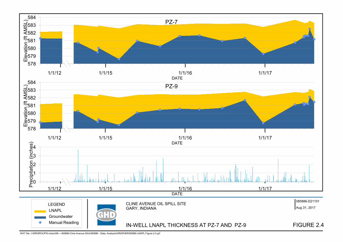
Figure 2.4 In-Well LNAPL Thickness at PZ-7 and PZ-9
Figure 2.5 LIF Results
Table Index Table 2.1 Gauging Summary
GHD | Design Investigation Report | 085886 (3) | Page ii
Appendix Index Appendix A Utility Clearance Summary
Appendix B Geophysical Analysis
Appendix C LNAPL Fingerprint Analysis
Appendix C.1 LNAPL Chromatograms Appendix C.2 LNAPL Physical Properties Analytical Reports Appendix C.3 Analysis of NAPL Samples (GSI Environmental)
Appendix D LIF Results
GHD | Design Investigation Report | 085886 (3) | Page 1
1. Introduction
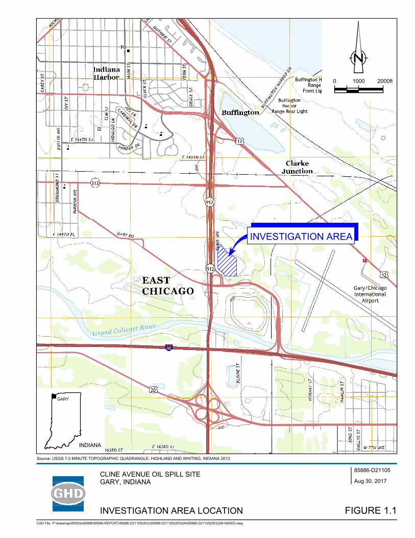
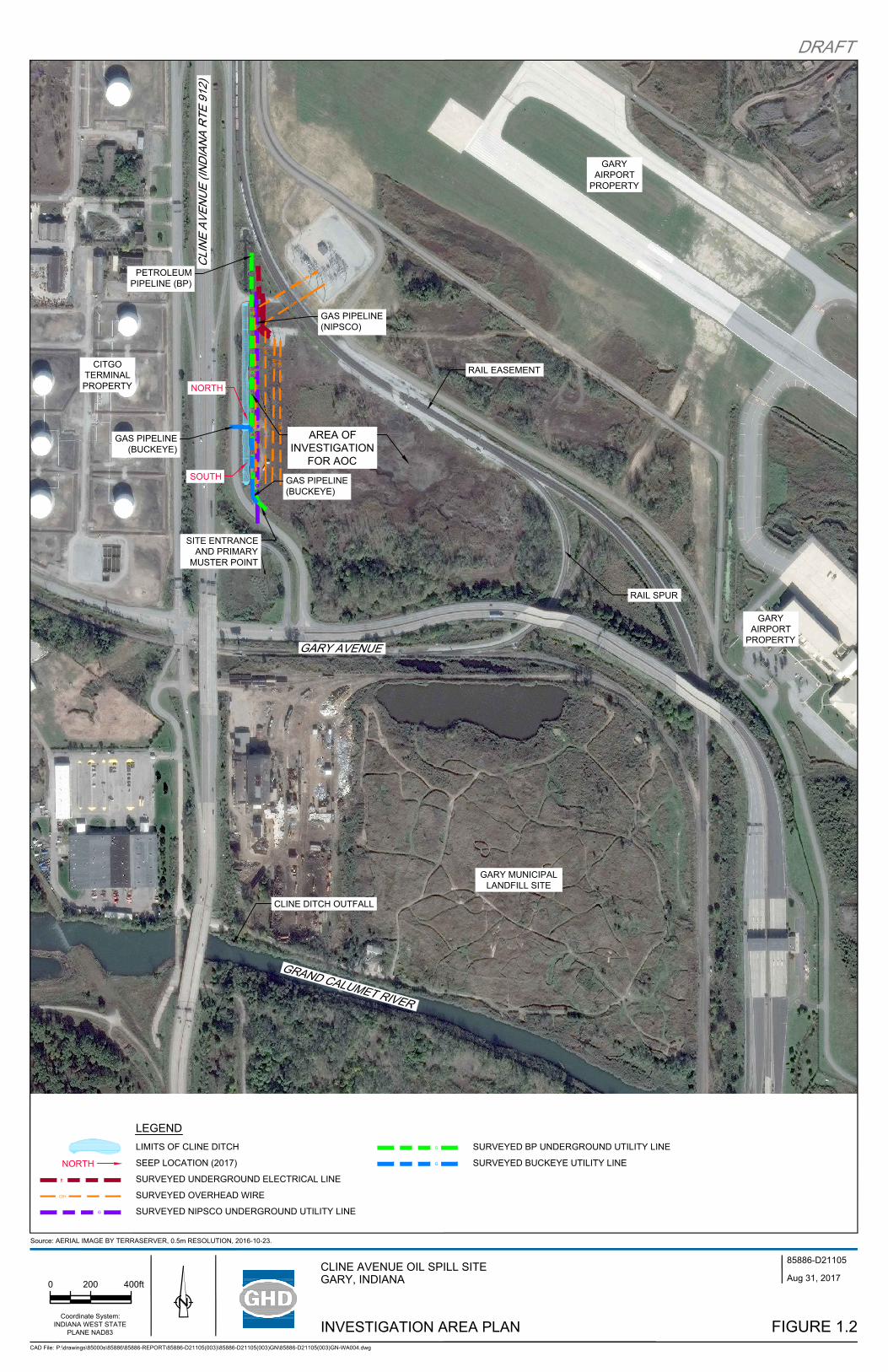
On behalf of Glenn Springs Holdings (GSH), a subsidiary of Occidental Petroleum Corporation, GHD Services Inc. (GHD) has prepared this Design Investigation Report (Report) to summarize the results from implementation of the Design Investigation/Focused Feasibility Study (DI/FFS) Work Plan for the Cline Avenue Oil Spill Site, in Gary, Indiana. The Report has been prepared in accordance with the Administrative Order on Consent (AOC) dated March 3, 2017 between Oxy USA, Inc. and United States Environmental Protection Agency (USEPA) Region V (RCRA-05-2017-0009). Figure 1.1 presents the investigation area location and Figure 1.2 presents the investigation area plan.
As detailed in the AOC and further agreed upon by USEPA and GSH attorneys, the purpose of this study was to investigate LNAPL seeps to the Cline Avenue ditch and to collect additional information in support of a feasibility assessment for potential remedial actions designed to mitigate petroleum sheens from continuing to impact the ditch.
This report has been prepared in accordance with Section III – B of the Scope of Work (SOW) provided in the AOC. The outline is as follows:
Section 1 Introduction
Section 2 Design Investigation Activity Summary
Section 3 Conclusions and Recommendation
2. Design Investigation Activity Summary
The following sections summarize activities associated with assessing the extent of mobile LNAPL contributing to the Cline Avenue ditch and in support of the development of a feasibility assessment for potential remedial actions associated with preventing petroleum sheens from impacting the ditch in accordance with AOC.
2.1 Investigation Area Mapping
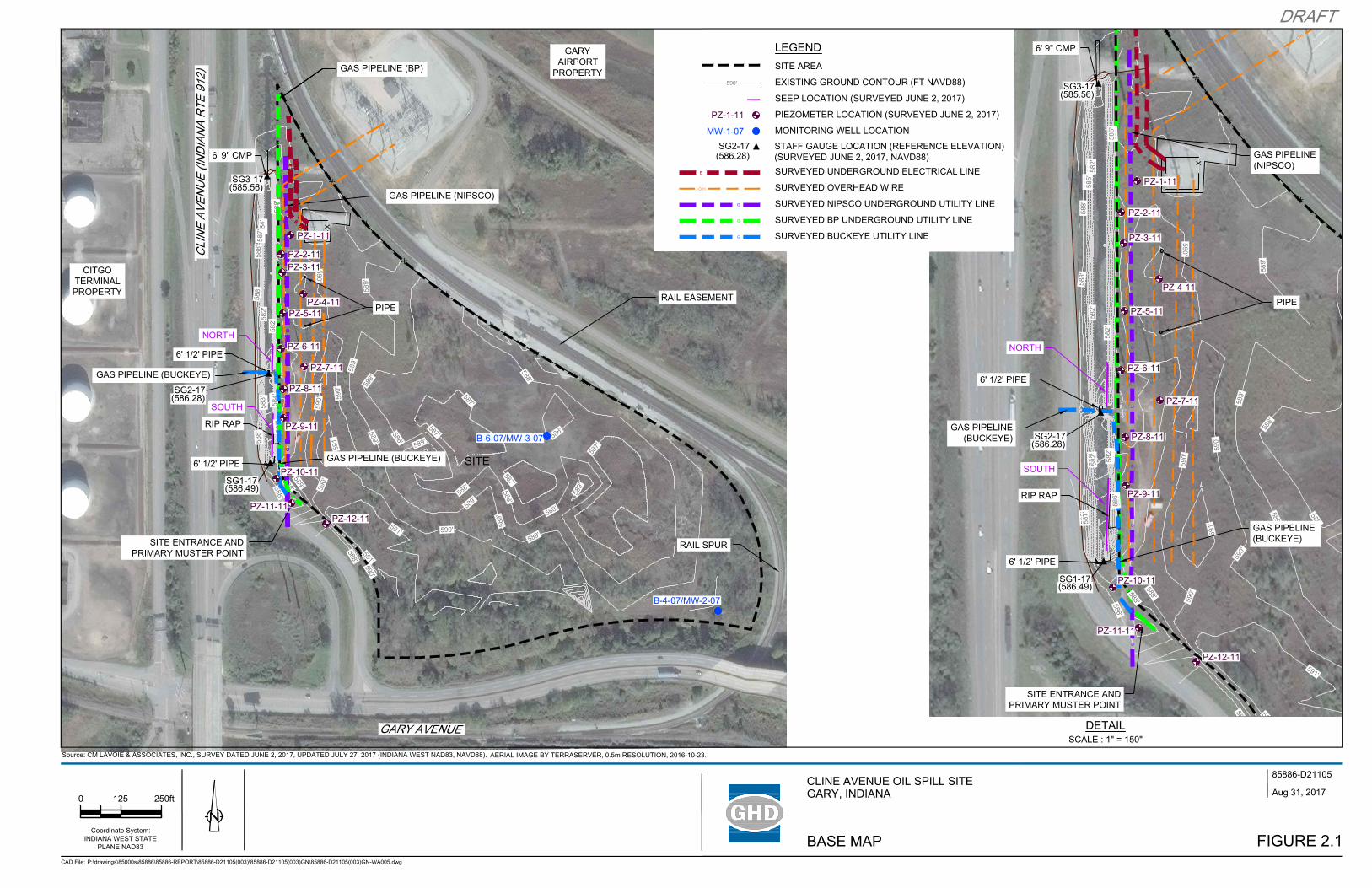
Investigation area mapping activities were completed to generate accurate figures depicting critical features including: seep locations, piezometer/well locations, buried pipelines/utilities, topography, etc. Investigation area mapping activities included both topographic geophysical surveys.
2.1.1 Topographic Mapping
A topographic survey of the investigation area was conducted between May 24th to May 26th, 2017 by C.M. Lavoie and Associates. The survey was completed in the Indiana West State Plane NAD83 horizontal coordinate system and the NAVD 88 vertical datum. The survey information obtained included the following:
• Piezometer, monitoring well, and staff gauge locations and elevations
• Seep locations and extents
GHD | Design Investigation Report | 085886 (3) | Page 2
• Ditch (top and bottom of bank and bridge/culverts)
• Proposed laser induced fluorescence (LIF) boring locations
• Utility locations (overhead and buried – based on existing pipeline markings)
• Spot elevations at 50-foot grid across investigation area (relatively flat ranging from 587 to 591 ft above mean sea level (AMSL))
• Setting three staff gauges at the culverts
• Other investigation area features including but not limited to: fencing, guard rails, edge of Cline Avenue Road
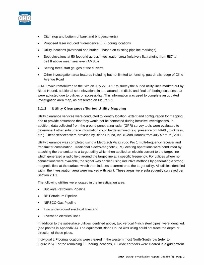
C.M. Lavoie remobilized to the Site on July 27, 2017 to survey the buried utility lines marked out by Blood Hound, additional spot elevations in and around the ditch, and final LIF boring locations that were adjusted due to utilities or accessibility. This information was used to complete an updated investigation area map, as presented on Figure 2.1.
2.1.2 Utility Clearances/Buried Utility Mapping
Utility clearance services were conducted to identify location, extent and configuration for mapping, and to provide assurance that they would not be contacted during intrusive investigations. In addition, data collected from the ground penetrating radar (GPR) survey tools were evaluated to determine if other subsurface information could be determined (e.g. presence of LNAPL, thickness, etc.). These services were provided by Blood Hound, Inc. (Blood Hound) from July 5th to 7th, 2017.
Utility clearance was completed using a Metrotech Vivax vLoc Pro 1 multi-frequency receiver and transmitter combination. Traditional electro-magnetic (EM) locating operations were conducted by attaching the transmitter to a target utility which then applied an electric current to the target line which generated a radio field around the target line at a specific frequency. For utilities where no connections were available, the signal was applied using inductive methods by generating a strong magnetic field at the surface which then induces a current onto the target utility. All utilities identified within the investigation area were marked with paint. These areas were subsequently surveyed per Section 2.1.1.
The following utilities were located in the investigation area:
• Buckeye Petroleum Pipeline
• BP Petroleum Pipeline
• NIPSCO Gas Pipeline
• Two underground electrical lines and
• Overhead electrical lines
In addition to the subsurface utilities identified above, two vertical 4-inch steel pipes, were identified. (see photos in Appendix A). The equipment Blood Hound was using could not trace the depth or direction of these pipes.
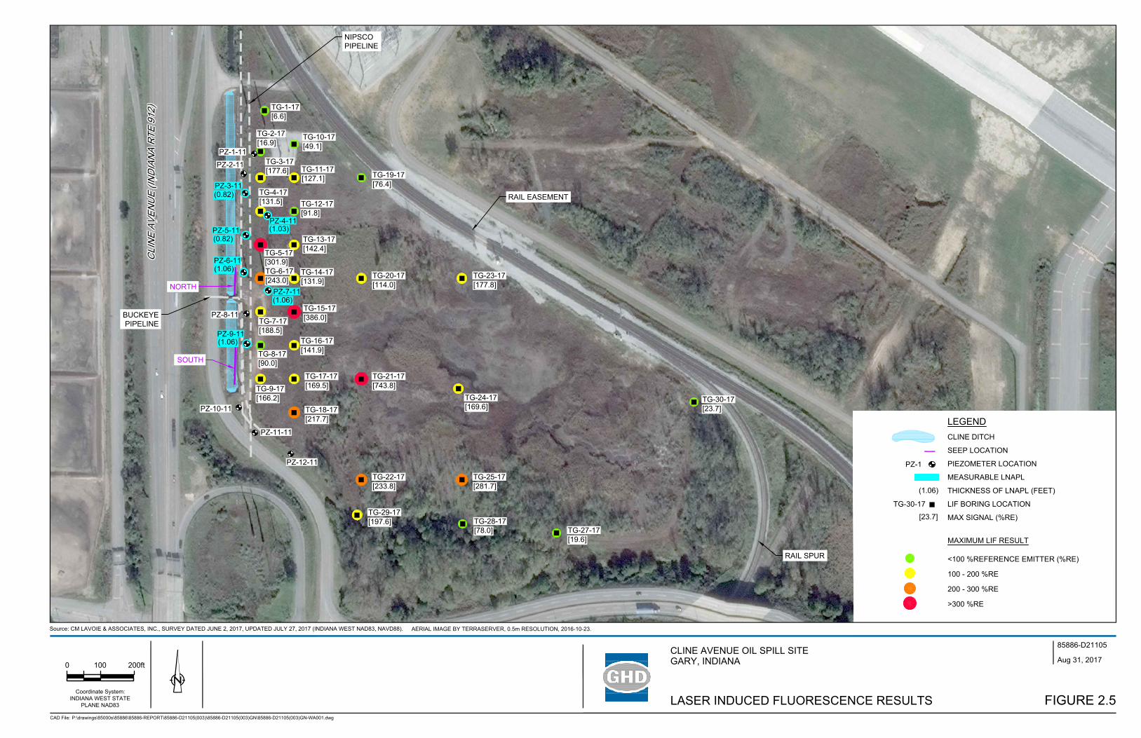
Individual LIF boring locations were cleared in the western most North-South row (refer to Figure 2.5). For the remaining LIF boring locations, 10’ wide corridors were cleared in a grid pattern
GHD | Design Investigation Report | 085886 (3) | Page 3
to provide flexibility to move LIF borings, should the real-time LIF field data require a change to the proposed locations.
On July 7th, 2017, advanced GPR surveying was performed by Blood Hound utilizing a SIR 4000 GPR unit with a 350 MHz antenna to determine whether the GPR data correlated with the LNAPL identified at the piezometers (P3, P4, P5, P6, P7, and P9) with measureable LNAPL (see Figure 2.5). Advanced GPR data was collected along 10 profiles aligned with the piezometers in the North-South direction, which covered the distances between piezometers 1 through 10. The data was provided to Environmental Geophysics Associates (EGA) for processing and is further discussed in Section 2.1.3.
2.1.3 Geophysical Analysis
The data collected from the advanced GPR survey was reviewed and assessed by EGA to determine if a better understanding of subsurface conditions could be obtained from the data.
Upon review, there was no reliable correlation between the advanced GPR survey data and Site conditions such as the presence or absence of LNAPL (e.g., as indicated by current/historical piezometer monitoring data). A copy of EGA’s report is provided in Appendix B.
2.2 Investigation Observations
A GHD’s LNAPL subject matter expert conducted a Site visit on July 12, 2017 to oversee the LIF boring installations and to observe conditions influencing LNAPL movement into the ditch. The following observations were made:
• The LIF borings are identifying hydrocarbon responses across most of the investigation area.
• Similar hydrocarbon responses have been identified across the investigation area as well as next to some of the piezometers that do not have measureable LNAPL. Therefore, the potential for LNAPL to be hydraulically mobile across the investigation area is not significant.
• Sheen/LNAPL is entering the ditch laterally from the sidewalls, which is likely from LNAPL in the immediate vicinity of the ditch.
• Sheen/LNAPL is also entering the ditch vertically from the bottom of the ditch through a process called ebullition (pressure/air bubbles dislodge otherwise immobile LNAPL).
2.3 LNAPL Fingerprint Analysis
In order to better understand the type and distribution of LNAPL, six samples of LNAPL were collected from existing piezometers with sufficient LNAPL during the initial gauging activities. The six samples were submitted to Pace Analytical Energy Services Laboratory for both chemical and physical property analysis.
2.3.1 Chemical Property Analysis
The six LNAPL samples were submitted on June 28th, 2017 and analyzed for C3 to C36 whole oil molecular characterization gas chromatography “fingerprint” by GC/FID as well as C8 to C40 full scan qualitative molecular characterization by GC/MS (refer to lab methods). The results of the
GHD | Design Investigation Report | 085886 (3) | Page 4
chemical analysis are summarized in Appendix C.1. The following observations were made regarding analysis of the chromatograms:
• The chromatograms appear to show similar age and types of hydrocarbon material
• LNAPL samples appear to contain a wide mixture of hydrocarbons
• The hydrocarbon mixture appears to consist of weathered gasoline, weathered diesel, and heavier hydrocarbon material (e.g., weathered crude oil)
2.3.2 Physical Property Analysis
The six LNAPL samples were submitted to Pace Analytical on June 26th, 2017 and analyzed for viscosity, surface tension and liquid properties. The analyses were subcontracted to Clark Testing. The results of the physical property analysis are summarized in Appendix C.2. The chemical and physical property analysis results were also analyzed by GSI Environmental Inc. (GSI). GSI’s observations were consistent with GHD’s observations. A copy of GSI’s evaluation is provided in Appendix C.3.
Upon review of the physical property data, the observations made on the chemical property analysis did not change (i.e., specific gravity and viscosity results were comparable and consistent with the mixture of petroleum LNAPL types described in Section 2.3.1).
2.4 Groundwater Investigation
The groundwater investigation activities included periodic gauging of piezometers and monitoring wells for LNAPL/groundwater level measurements. In addition, surface water level measurements were measured from the three staff gauges along the ditch.
2.4.1 Water/LNAPL Level Monitoring
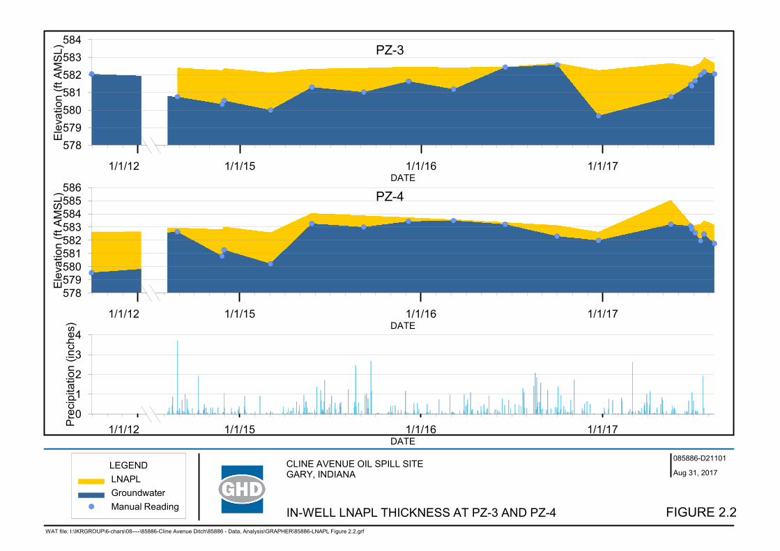
Water level/LNAPL measurements were collected in May and August from the twelve piezometers (PZ-1 to PZ-12) and from two monitoring wells (MW-2 and MW-3) to evaluate trends in LNAPL thickness and groundwater levels. Measurements were taken with a dual phase probe with electrical sounding device and accuracy of ±0.01 feet, to determine the depth to water or oil (where present) and oil-water interface. The date, depth to product, and depth to water was recorded, and used to calculate the LNAPL thickness (where present) and corrected groundwater elevation (where LNAPL was present). These results are summarized in Table 2.1. Figures 2.2, 2.3 and 2.4 present a graphical depiction of LNAPL thicknesses and water table elevations.
2.4.2 Surface Water Level Monitoring
Three staff gauges were set during the surveying activities conducted in late May 2017 along the ditch (SG-1, SG-2, and SG-3), which are shown on Figure 2.1. The staff gauges consist of surveyed markings on the existing bridges/culverts that cross the ditch. The staff gauges were used to measure surface water levels/elevations in the ditch for comparison to the groundwater elevations from the piezometers/wells. The use of the bridges/culverts was to ensure longevity of the staff gauges through freezing conditions. Ditch water levels/elevations were measured in August at the same time as the piezometers and monitoring wells. Measurements were taken with an electrical
GHD | Design Investigation Report | 085886 (3) | Page 5
sounding device with an accuracy of ±0.01 feet. The depth to water and the date of measurement were recorded and are also summarized in Table 2.1.
2.5 LIF Investigation
An LIF investigation was conducted to assist in determining the horizontal and vertical extent of residual hydrocarbons in soil. A total of 29 LIF borings were completed by Dakota Technologies (Dakota) between July 10 and 14, 2017, with the greater concentration of borings being completed adjacent to the ditch and fewer borings being completed further to the east.
2.5.1 Methodologies
Prior to mobilization, a representative sample of LNAPL was submitted to Dakota Technologies (Dakota) to verify the appropriate laser to be used as part of the LIF investigation. Dakota identified that the Tar Green Optical Screening Tool (TarGOST) LIF system was the appropriate unit for this investigation. The TarGOST is typically used to investigate weathered or heavier types of hydrocarbons. The LIF probe was advanced in the subsurface using a GeoProbe™. As such, no soil cuttings were produced during the LIF investigation. Locations were backfilled with cement-bentonite grout immediately following the completion of each LIF push with the appropriate surface restoration.
The LIF probe is equipped with a sapphire window through which a laser is directed. The probe is advanced using a specialized direct-push probe. The laser light is adsorbed by hydrocarbons as the probe is advanced. This addition of energy (photons) causes hydrocarbons to release excess energy as light (fluoresce). A portion of the fluorescence emitted from any encountered hydrocarbons is returned through the sapphire window and conveyed by a fiber optic cable to a detection system at the surface. The emission data from the pulsed laser light is averaged into one reading per one-second intervals and is recorded continuously. The emission data is reported as percent of the fluorescence intensity of a "reference emitter" (%RE). The Reference Emitter is a standard proprietary hydrocarbon mixture used to calibrate the equipment, and LIF readings are a quantification of intensity relative to the fluorescence produced by it. For example, an LIF location producing a reading of 100%RE is fluorescing at exactly the same intensity as the standard hydrocarbon mixture. Other things being equal, LIF response is proportional to the amount of hydrocarbons present (i.e., LIF response is proportional to hydrocarbon saturation). In addition, the LIF instrumentation measures the intensities of four different wavelengths of light produced when a given hydrocarbon fluoresces. The proportions of each wavelength that comprise the overall fluorescence response are unique to a given petroleum product type and are referred to as the spectral fingerprint. These wave lengths are illustrated on the individual LIF logs for each location.
2.5.2 Findings
The LIF boring locations and maximum response at each boring is presented on Figure 2.5. The %RE ranged from 6.6 to 744, confirming the typical scenario of highly variable LNAPL saturation levels across an old LNAPL site. The highest %RE was observed at TG-21-17 (approximately 300’ east of the ditch). Other elevated %RE readings were not consistent with a single source area which may indicated multiple source events or preferential migration pathways for the LNAPL. It is noted that the spacing of the LIF points in the Site interior was large enough that additional
GHD | Design Investigation Report | 085886 (3) | Page 6
investigation may produce results that adjust this interpretation. The northern, eastern, and southern boundaries of the investigation had lower %RE.
The intensity of the responses broadly indicates residual hydrocarbon saturation levels. Most of the hydrocarbon responses, including some of the highest responses, are below the water table, which typically signifies that the LNAPL is largely immobile residual. This suggests that much of the impact to the ditch is resulting from residual LNAPL impacts in the vicinity of the ditch, and is not due to bulk movement of LNAPL from the interior of the Site towards the ditch currently.
A review of the spectral fingerprints from the LIF borings that are presented on the TarGOST output logs indicate a somewhat consistent mixture of LNAPL types across the Site.
3. Conceptual Site Model of LNAPL Transport
Historical data as well as the data recently collected have been analyzed to develop a conceptual site model. These data indicate that LNAPL is entering the ditch through two transport models:
1. Laterally from sidewalls – immediate vicinity of ditch and not as bulk movement internal to the Site (due to the lack of resistance at the ditch bank surface that allows residual LNAPL movement, whereas similarly saturated soil would not allow LNAPL movement in the interior of the Site).
2. Ebullition – pressure/air bubbles periodically dislodge otherwise immobile residual hydrocarbons from beneath the ditch.
The LNAPL is old and primarily located below the water table; therefore, the bulk of the Site LNAPL is likely to be present as hydraulically immobile residual. Ditch booming activities have documented generally stable conditions of oil entering the ditch for several years with some fluctuations.
4. Conclusions
Evaluated data, including the LNAPL chromatograms, LNAPL physical property analysis, and the LIF results, indicate similar types/mixtures of hydrocarbons across the investigated area and a somewhat random geographic distribution and concentration gradient. The concentrations of hydrocarbons do not map from a centralized source. The concentration of mapped hydrocarbons appear higher near the existing hydrocarbon pipeline infrastructure.
The LIF results identified the presence of residual hydrocarbons across the area that was investigated, however, most of the LIF hydrocarbon responses were below the water table, which typically signifies that it the residual hydrocarbons are immobile.
Visual observation of LNAPL entering the ditch identified that LNAPL was entering the ditch both through lateral seepage and vertically from the bottom of the ditch through a process called ebullition.
Additional preliminary design investigation (PDI) activities are planned to support the evaluation of potential remedial alternatives.
0 1000 2000ft
Source: USGS 7.5 MINUTE TOPOGRAPHIC QUADRANGLE; HIGHLAND AND WHITING, INDIANA 2013
GARY
INDIANA
INVESTIGATION AREA
CAD File: P:\drawings\85000s\85886\85886-REPORT\85886-D21105(003)\85886-D21105(003)GN\85886-D21105(003)GN-WA003.dwg
Aug 30, 2017
85886-D21105
FIGURE 1.1
CLINE AVENUE OIL SPILL SITEGARY, INDIANA
INVESTIGATION AREA LOCATION
O/H
O/H
O/H
O/H
O/H
O/H
O/H
O/H
O/H
O/H
O/H
E
G
G
GG
G
GG
G
GG
G
GG
G
GG
G
GG
G
G
GG
G
G
GG
EEE
O/H
O/H
O/H
O/H
O/H
O/H
O/H
O/H
O/H
O/H
O/H
GARY MUNICIPALLANDFILL SITE
CLINE DITCH OUTFALL
GARYAIRPORT
PROPERTY
GARYAIRPORT
PROPERTY
CITGOTERMINALPROPERTY
RAIL SPUR
RAIL EASEMENT
SITE ENTRANCEAND PRIMARY
MUSTER POINT
PETROLEUMPIPELINE (BP)
SOUTH
NORTH
AREA OFINVESTIGATION
FOR AOC
GAS PIPELINE(NIPSCO)
GAS PIPELINE(BUCKEYE)
G
GAS PIPELINE(BUCKEYE)
0 200 400ft 0.0025
Coordinate System:INDIANA WEST STATE
PLANE NAD83
CAD File: P:\drawings\85000s\85886\85886-REPORT\85886-D21105(003)\85886-D21105(003)GN\85886-D21105(003)GN-WA004.dwg
Aug 31, 2017
85886-D21105
FIGURE 1.2
CLINE AVENUE OIL SPILL SITEGARY, INDIANA
INVESTIGATION AREA PLAN
LIMITS OF CLINE DITCH
LEGEND
SEEP LOCATION (2017)
Source: AERIAL IMAGE BY TERRASERVER, 0.5m RESOLUTION, 2016-10-23.
NORTH
SURVEYED UNDERGROUND ELECTRICAL LINE
SURVEYED OVERHEAD WIRE
E
O/H
SURVEYED NIPSCO UNDERGROUND UTILITY LINEG
SURVEYED BP UNDERGROUND UTILITY LINEG
SURVEYED BUCKEYE UTILITY LINEG
X
X
X
X
X
X
X
X
O/H
O/H
O/H
O/H
O/H
O/H
O/H
O/H
O/H
O/H
O/H
O/H
O/H
O/H
O/H
XX
O/H
O/H
O/H
6' 1/2' PIPE
RIP RAP
6' 1/2' PIPE
6' 9" CMP
GAS PIPELINE (BP)
E
E
G
GG
G
GG
G
E
GAS PIPELINE (NIPSCO)
NORTH
SOUTH
GG
GG
G
GG
GG
G
G
GG
GG
G
G
GG
GG
G
G
GG
GG
G
G
G
GAS PIPELINE (BP)
G
GG
G
GG
G
GAS PIPELINE (BP)
G
GG
G
GG
G
E
E
EE
E
EEE
E
O/H
O/H
O/H
O/H
O/H
O/H
O/H
O/H
O/H
O/H
O/H
O/H
O/H
O/H
O/H
O/H
O/H
O/H
GG
GAS PIPELINE (BUCKEYE)
GAS PIPELINE (BUCKEYE)
GARYAIRPORT
PROPERTY
CITGOTERMINALPROPERTY
RAIL SPUR
SITE
RAIL EASEMENT
SITE ENTRANCE ANDPRIMARY MUSTER POINT
PIPE
PZ-12-11PZ-11-11
SG1-17(586.49)
PZ-10-11
PZ-9-11
PZ-8-11
PZ-7-11
PZ-6-11
PZ-5-11PZ-4-11
PZ-3-11
PZ-1-11
PZ-2-11
SG2-17(586.28)
SG3-17(585.56)
B-6-07/MW-3-07
B-4-07/MW-2-07
X
X
X
X
X
X
X
XO
/HO
/HO
/HO
/HO
/HO
/HO
/H
O/H
O/H
O/H
O/H
O/H
O/H
O/H
O/H
O/H
O/H
O/H
O/H
O/H
O/H
O/H
O/H
O/H
O/H
O/H
O/H
O/H
O/H
O/H
O/H
G
GG
GG
GG
GG
GE
E
E
E
GG
G
GG
G
GG
G
G
SOUTH
NORTH
6' 9" CMP
6' 1/2' PIPE
RIP RAP
6' 1/2' PIPE
GG
G
G
GAS PIPELINE(BUCKEYE)
PZ-11-11
PZ-12-11
PZ-2-11
PZ-1-11
PZ-3-11
PZ-4-11
PZ-5-11
PZ-6-11
PZ-7-11
PZ-8-11
PZ-9-11
PZ-10-11SG1-17(586.49)
SG3-17(585.56)
SITE ENTRANCE ANDPRIMARY MUSTER POINT
PIPE
SG2-17(586.28)
GAS PIPELINE(NIPSCO)
GAS PIPELINE(BUCKEYE)
0 125 250ft 0.004
Coordinate System:INDIANA WEST STATE
PLANE NAD83
CAD File: P:\drawings\85000s\85886\85886-REPORT\85886-D21105(003)\85886-D21105(003)GN\85886-D21105(003)GN-WA005.dwg
Aug 31, 2017
85886-D21105
FIGURE 2.1
CLINE AVENUE OIL SPILL SITEGARY, INDIANA
BASE MAP
Source: CM LAVOIE & ASSOCIATES, INC., SURVEY DATED JUNE 2, 2017, UPDATED JULY 27, 2017 (INDIANA WEST NAD83, NAVD88). AERIAL IMAGE BY TERRASERVER, 0.5m RESOLUTION, 2016-10-23.
DETAILSCALE : 1" = 150"
SITE AREA
LEGEND
MONITORING WELL LOCATIONMW-1-07
SEEP LOCATION (SURVEYED JUNE 2, 2017)
EXISTING GROUND CONTOUR (FT NAVD88)
SG2-17(586.28)
SURVEYED UNDERGROUND ELECTRICAL LINE
SURVEYED OVERHEAD WIRE
E
O/H
PIEZOMETER LOCATION (SURVEYED JUNE 2, 2017)PZ-1-11
SURVEYED NIPSCO UNDERGROUND UTILITY LINEG
SURVEYED BP UNDERGROUND UTILITY LINEG
SURVEYED BUCKEYE UTILITY LINEG
STAFF GAUGE LOCATION (REFERENCE ELEVATION)(SURVEYED JUNE 2, 2017, NAVD88)
CLINE AVENUE OIL SPILL SITEGARY, INDIANA
IN-WELL LNAPL THICKNESS AT PZ-3 AND PZ-4 FIGURE 2.2
085886-D21101
Aug 31, 2017
WAT file: I:\IKRGROUP\6-chars\08----\85886-Cline Avenue Ditch\85886 - Data, Analysis\GRAPHER\85886-LNAPL Figure 2.2.grf
1/1/12 1/1/15 1/1/16 1/1/17DATE
578579580581582583584585586
Ele
vatio
n(ft
AM
SL)
1/1/12 1/1/15 1/1/16 1/1/17DATE
578579580581582583584
Ele
vatio
n(ft
AM
SL)
LEGENDLNAPLGroundwaterManual Reading
PZ-3
PZ-4
1/1/12 1/1/15 1/1/16 1/1/17DATE
0
1
2
3
4
Pre
cipi
tatio
n(in
ches
)
CLINE AVENUE OIL SPILL SITEGARY, INDIANA
IN-WELL LNAPL THICKNESS AT PZ-5 AND PZ-6 FIGURE 2.3
085886-D21101
Aug 31, 2017
WAT file: I:\IKRGROUP\6-chars\08----\85886-Cline Avenue Ditch\85886 - Data, Analysis\GRAPHER\85886-LNAPL Figure 2.3.grf
1/1/12 1/1/15 1/1/16 1/1/17DATE
578579580581582583584
Ele
vatio
n(ft
AM
SL)
1/1/12 1/1/15 1/1/16 1/1/17DATE
578579580581582583584
Ele
vatio
n(ft
AM
SL)
LEGENDLNAPLGroundwaterManual Reading
PZ-5
PZ-6
1/1/12 1/1/15 1/1/16 1/1/17DATE
0
1
2
3
4
Pre
cipi
tatio
n(in
ches
)
CLINE AVENUE OIL SPILL SITEGARY, INDIANA
IN-WELL LNAPL THICKNESS AT PZ-7 AND PZ-9 FIGURE 2.4
085886-D21101
Aug 31, 2017
WAT file: I:\IKRGROUP\6-chars\08----\85886-Cline Avenue Ditch\85886 - Data, Analysis\GRAPHER\85886-LNAPL Figure 2.4.grf
1/1/12 1/1/15 1/1/16 1/1/17DATE
578579580581582583584
Ele
vatio
n(ft
AM
SL)
1/1/12 1/1/15 1/1/16 1/1/17DATE
578579580581582583584
Ele
vatio
n(ft
AM
SL)
LEGENDLNAPLGroundwaterManual Reading
PZ-7
PZ-9
1/1/12 1/1/15 1/1/16 1/1/17DATE
0
1
2
3
4
Pre
cipi
tatio
n(in
ches
)
GARYAIRPORT
RAIL SPUR
RAIL EASEMENT
GG
G
G
GG
G
GG
GG
GG
GG
GG
G
GG
GG
BUCKEYEPIPELINE
NIPSCOPIPELINE
NORTH
SOUTH
PZ-12-11
PZ-11-11
PZ-10-11
PZ-8-11TG-7-17[188.5]
TG-8-17[90.0]
TG-9-17[166.2]
TG-17-17[169.5]
TG-18-17[217.7]
TG-16-17[141.9]
TG-15-17[386.0]
TG-14-17[131.9]
TG-6-17[243.0]
TG-5-17[301.9]
TG-13-17[142.4]
PZ-1-11
PZ-2-11
TG-4-17[131.5]
TG-3-17[177.6]
TG-2-17[16.9]
TG-1-17[6.6]
TG-10-17[49.1]
TG-11-17[127.1]
TG-12-17[91.8]
TG-19-17[76.4]
TG-20-17[114.0]
TG-23-17[177.8]
TG-21-17[743.8]
TG-24-17[169.6]
TG-22-17[233.8]
TG-29-17[197.6]
TG-25-17[281.7]
TG-28-17[78.0] TG-27-17
[19.6]
TG-30-17[23.7]
PZ-3-11(0.82)
PZ-5-11(0.82)
PZ-6-11(1.06)
PZ-7-11(1.06)
PZ-9-11(1.06)
PZ-4-11(1.03)
0 100 200ft
Coordinate System:INDIANA WEST STATE
PLANE NAD83
CAD File: P:\drawings\85000s\85886\85886-REPORT\85886-D21105(003)\85886-D21105(003)GN\85886-D21105(003)GN-WA001.dwg
Aug 31, 2017
85886-D21105
FIGURE 2.5
CLINE AVENUE OIL SPILL SITEGARY, INDIANA
LASER INDUCED FLUORESCENCE RESULTS
CLINE DITCH
LEGEND
LIF BORING LOCATIONTG-30-17
[23.7]
PIEZOMETER LOCATIONPZ-1
(1.06)
MAXIMUM LIF RESULT
<100 %REFERENCE EMITTER (%RE)
100 - 200 %RE
200 - 300 %RE
>300 %RE
MEASURABLE LNAPL
Source: CM LAVOIE & ASSOCIATES, INC., SURVEY DATED JUNE 2, 2017, UPDATED JULY 27, 2017 (INDIANA WEST NAD83, NAVD88). AERIAL IMAGE BY TERRASERVER, 0.5m RESOLUTION, 2016-10-23.
THICKNESS OF LNAPL (FEET)
MAX SIGNAL (%RE)
SEEP LOCATION
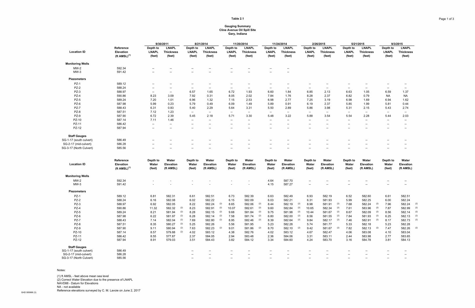
Table 2.1
Gauging Summary Cline Avenue Oil Spill Site
Gary, Indiana
Page 1 of 3
Reference Depth to LNAPL Depth to LNAPL Depth to LNAPL Depth to LNAPL Depth to LNAPL Depth to LNAPL Depth to LNAPLLocation ID Elevation LNAPL Thickness LNAPL Thickness LNAPL Thickness LNAPL Thickness LNAPL Thickness LNAPL Thickness LNAPL Thickness
(ft AMSL)(1) (feet) (feet) (feet) (feet) (feet) (feet) (feet) (feet) (feet) (feet) (feet) (feet) (feet) (feet)
Monitoring WellsMW-2 592.34 -- -- -- -- -- -- -- --MW-3 591.42 -- -- -- -- -- -- -- --
PiezometersPZ-1 589.12 -- -- -- -- -- -- -- -- -- -- -- -- -- --PZ-2 588.24 -- -- -- -- -- -- -- -- -- -- -- -- -- --PZ-3 588.97 -- -- 6.57 1.65 6.72 1.93 6.60 1.84 6.85 2.13 6.63 1.05 6.59 1.37PZ-4 590.86 8.23 3.09 7.92 0.31 8.05 2.02 7.84 1.76 8.28 2.37 6.82 0.79 NA NAPZ-5 589.24 7.20 1.01 6.96 1.32 7.15 2.53 6.98 2.77 7.25 3.19 6.98 1.69 6.94 1.62PZ-6 587.98 5.99 0.23 5.79 0.49 6.09 1.49 5.89 0.91 6.19 2.37 5.85 1.99 5.81 0.44PZ-7 588.43 6.31 0.83 5.40 2.29 5.64 3.31 5.50 2.89 5.86 3.98 5.31 2.15 5.43 2.74PZ-8 587.51 7.12 1.23 -- -- -- -- -- -- -- -- -- -- -- --PZ-9 587.90 6.72 2.39 5.45 2.18 5.71 3.30 5.48 3.22 5.88 3.54 5.54 2.28 5.44 2.03
PZ-10 587.14 7.11 1.46 -- -- -- -- -- -- -- -- -- -- -- --PZ-11 586.42 -- -- -- -- -- -- -- -- -- -- -- -- -- --PZ-12 587.94 -- -- -- -- -- -- -- -- -- -- -- -- -- --
Staff GaugesSG-1-17 (south culvert) 586.49 -- -- -- -- -- -- -- -- -- -- -- -- -- --SG-2-17 (mid-culvert) 586.28 -- -- -- -- -- -- -- -- -- -- -- -- -- --
SG-3-17 (North Culvert) 585.56 -- -- -- -- -- -- -- -- -- -- -- -- -- --
Reference Depth to Water Depth to Water Depth to Water Depth to Water Depth to Water Depth to Water Depth to WaterLocation ID Elevation Water Elevation Water Elevation Water Elevation Water Elevation Water Elevation Water Elevation Water Elevation
(ft AMSL)(1) (feet) (ft AMSL) (feet) (ft AMSL) (feet) (ft AMSL) (feet) (ft AMSL) (feet) (ft AMSL) (feet) (ft AMSL) (feet) (ft AMSL)
Monitoring WellsMW-2 592.34 - - - - - - 4.64 587.70 -- -- -- -- -- --MW-3 591.42 - - - - - - 4.15 587.27 -- -- -- -- -- --
PiezometersPZ-1 589.12 6.81 582.31 6.61 582.51 6.73 582.39 6.63 582.49 6.93 582.19 6.52 582.60 6.61 582.51PZ-2 588.24 6.16 582.08 6.02 582.22 6.15 582.09 6.03 582.21 6.31 581.93 5.99 582.25 6.00 582.24PZ-3 588.97 6.92 582.05 8.22 582.24 (2) 8.65 582.06 (2) 8.44 582.19 (2) 8.98 581.91 (2) 7.68 582.24 (2) 7.96 582.24 (2)
PZ-4 590.86 11.32 582.32 (2) 8.23 582.91 (2) 10.07 582.61 (2) 9.60 582.84 (2) 10.65 582.34 (2) 7.61 583.96 (2) 7.87 582.99 (2)
PZ-5 589.24 8.21 581.94 (2) 8.28 582.15 (2) 9.68 581.84 (2) 9.75 581.98 (2) 10.44 581.67 (2) 8.67 582.09 (2) 8.56 582.14 (2)
PZ-6 587.98 6.22 581.97 (2) 6.28 582.14 (2) 7.58 581.74 (2) 6.80 582.00 (2) 8.56 581.55 (2) 7.84 581.93 (2) 6.25 582.13 (2)
PZ-7 588.43 7.14 582.04 (2) 7.69 582.80 (2) 8.95 582.46 (2) 8.39 582.64 (2) 9.84 582.17 (2) 7.46 582.91 (2) 8.17 582.73 (2)
PZ-8 587.51 8.35 580.27 (2) 5.25 582.26 5.56 581.95 5.23 582.28 5.74 581.77 5.33 582.18 5.23 582.28PZ-9 587.90 9.11 580.94 (2) 7.63 582.23 (2) 9.01 581.86 (2) 8.70 582.10 (2) 9.42 581.67 (2) 7.82 582.13 (2) 7.47 582.26 (2)
PZ-10 587.14 8.57 579.88 (2) 4.02 583.12 4.38 582.76 4.02 583.12 4.67 582.47 4.06 583.08 4.10 583.04PZ-11 586.42 8.55 577.87 2.37 584.05 2.94 583.48 2.36 584.06 3.31 583.11 2.44 583.98 2.77 583.65PZ-12 587.94 8.91 579.03 3.51 584.43 3.82 584.12 3.34 584.60 4.24 583.70 3.16 584.78 3.81 584.13
Staff GaugesSG-1-17 (south culvert) 586.49 -- -- -- -- -- -- -- -- -- -- -- --SG-2-17 (mid-culvert) 586.28 -- -- -- -- -- -- -- -- -- -- -- --
SG-3-17 (North Culvert) 585.56 -- -- -- -- -- -- -- -- -- -- -- --
Notes:
(1) ft AMSL - feet above mean sea level(2) Correct Water Elevation due to the presence of LNAPLNAVD88 - Datum for ElevationsNA - not availableReference elevations surveyed by C. M. Lavoie on June 2, 2017
11/20/2014 2/26/2015 5/21/2015 9/3/20159/30/2011 8/21/2014 11/24/2014
GHD 085886 (3)
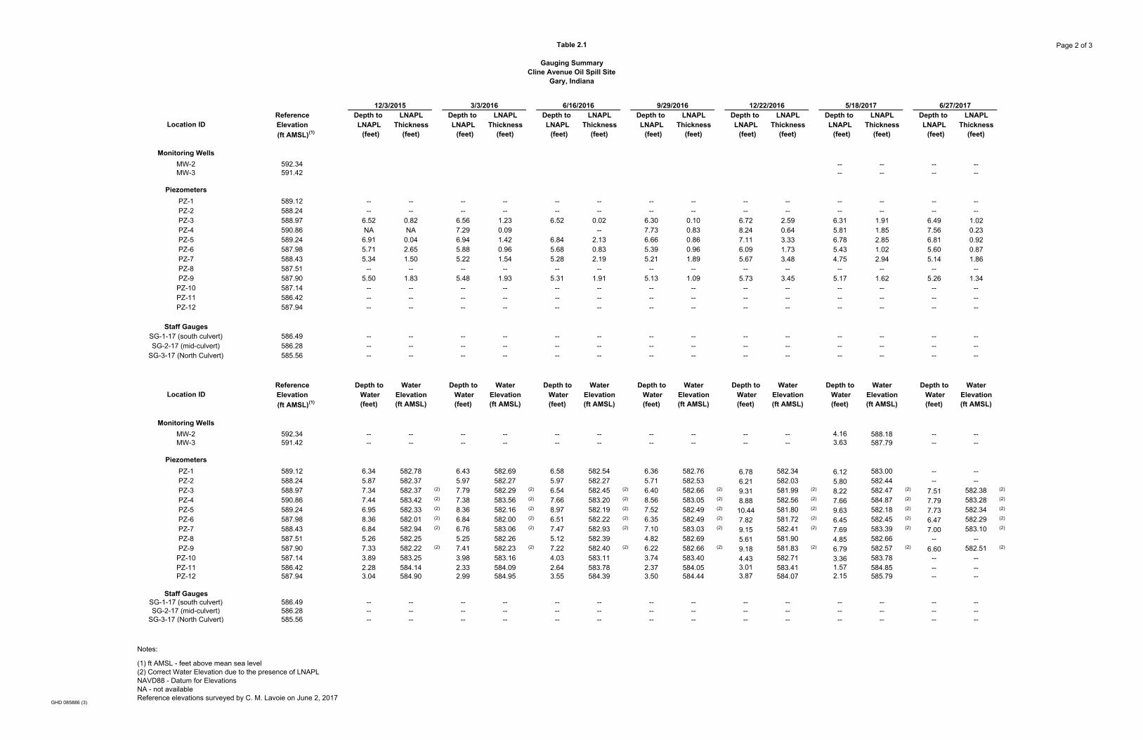
Table 2.1
Gauging Summary Cline Avenue Oil Spill Site
Gary, Indiana
Page 2 of 3
ReferenceLocation ID Elevation
(ft AMSL)(1)
Monitoring WellsMW-2 592.34MW-3 591.42
PiezometersPZ-1 589.12PZ-2 588.24PZ-3 588.97PZ-4 590.86PZ-5 589.24PZ-6 587.98PZ-7 588.43PZ-8 587.51PZ-9 587.90
PZ-10 587.14PZ-11 586.42PZ-12 587.94
Staff GaugesSG-1-17 (south culvert) 586.49SG-2-17 (mid-culvert) 586.28
SG-3-17 (North Culvert) 585.56
Notes:
(1) ft AMSL - feet above mean sea level(2) Correct Water Elevation due to the presence of LNAPLNAVD88 - Datum for ElevationsNA - not availableReference elevations surveyed by C. M. Lavoie on June 2, 2017
Depth to LNAPL Depth to LNAPL Depth to LNAPL Depth to LNAPL Depth to LNAPL Depth to LNAPL Depth to LNAPLLNAPL Thickness LNAPL Thickness LNAPL Thickness LNAPL Thickness LNAPL Thickness LNAPL Thickness LNAPL Thickness (feet) (feet) (feet) (feet) (feet) (feet) (feet) (feet) (feet) (feet) (feet) (feet) (feet) (feet)
-- -- -- ---- -- -- --
-- -- -- -- -- -- -- -- -- -- -- -- -- ---- -- -- -- -- -- -- -- -- -- -- -- -- --
6.52 0.82 6.56 1.23 6.52 0.02 6.30 0.10 6.72 2.59 6.31 1.91 6.49 1.02NA NA 7.29 0.09 -- 7.73 0.83 8.24 0.64 5.81 1.85 7.56 0.23
6.91 0.04 6.94 1.42 6.84 2.13 6.66 0.86 7.11 3.33 6.78 2.85 6.81 0.925.71 2.65 5.88 0.96 5.68 0.83 5.39 0.96 6.09 1.73 5.43 1.02 5.60 0.875.34 1.50 5.22 1.54 5.28 2.19 5.21 1.89 5.67 3.48 4.75 2.94 5.14 1.86
-- -- -- -- -- -- -- -- -- -- -- -- -- --5.50 1.83 5.48 1.93 5.31 1.91 5.13 1.09 5.73 3.45 5.17 1.62 5.26 1.34
-- -- -- -- -- -- -- -- -- -- -- -- -- ---- -- -- -- -- -- -- -- -- -- -- -- -- ---- -- -- -- -- -- -- -- -- -- -- -- -- --
-- -- -- -- -- -- -- -- -- -- -- -- -- ---- -- -- -- -- -- -- -- -- -- -- -- -- ---- -- -- -- -- -- -- -- -- -- -- -- -- --
Depth to Water Depth to Water Depth to Water Depth to Water Depth to Water Depth to Water Depth to Water Water Elevation Water Elevation Water Elevation Water Elevation Water Elevation Water Elevation Water Elevation(feet) (ft AMSL) (feet) (ft AMSL) (feet) (ft AMSL) (feet) (ft AMSL) (feet) (ft AMSL) (feet) (ft AMSL) (feet) (ft AMSL)
-- -- -- -- -- -- -- -- -- -- 4.16 588.18 -- ---- -- -- -- -- -- -- -- -- -- 3.63 587.79 -- --
6.34 582.78 6.43 582.69 6.58 582.54 6.36 582.76 6.78 582.34 6.12 583.00 -- --5.87 582.37 5.97 582.27 5.97 582.27 5.71 582.53 6.21 582.03 5.80 582.44 -- --7.34 582.37 (2) 7.79 582.29 (2) 6.54 582.45 (2) 6.40 582.66 (2) 9.31 581.99 (2) 8.22 582.47 (2) 7.51 582.38 (2)
7.44 583.42 (2) 7.38 583.56 (2) 7.66 583.20 (2) 8.56 583.05 (2) 8.88 582.56 (2) 7.66 584.87 (2) 7.79 583.28 (2)
6.95 582.33 (2) 8.36 582.16 (2) 8.97 582.19 (2) 7.52 582.49 (2) 10.44 581.80 (2) 9.63 582.18 (2) 7.73 582.34 (2)
8.36 582.01 (2) 6.84 582.00 (2) 6.51 582.22 (2) 6.35 582.49 (2) 7.82 581.72 (2) 6.45 582.45 (2) 6.47 582.29 (2)
6.84 582.94 (2) 6.76 583.06 (2) 7.47 582.93 (2) 7.10 583.03 (2) 9.15 582.41 (2) 7.69 583.39 (2) 7.00 583.10 (2)
5.26 582.25 5.25 582.26 5.12 582.39 4.82 582.69 5.61 581.90 4.85 582.66 -- --7.33 582.22 (2) 7.41 582.23 (2) 7.22 582.40 (2) 6.22 582.66 (2) 9.18 581.83 (2) 6.79 582.57 (2) 6.60 582.51 (2)
3.89 583.25 3.98 583.16 4.03 583.11 3.74 583.40 4.43 582.71 3.36 583.78 -- --2.28 584.14 2.33 584.09 2.64 583.78 2.37 584.05 3.01 583.41 1.57 584.85 -- --3.04 584.90 2.99 584.95 3.55 584.39 3.50 584.44 3.87 584.07 2.15 585.79 -- --
-- -- -- -- -- -- -- -- -- -- -- -- -- ---- -- -- -- -- -- -- -- -- -- -- -- -- ---- -- -- -- -- -- -- -- -- -- -- -- -- --
9/29/2016 12/22/201612/3/2015 3/3/2016 6/16/2016 6/27/20175/18/2017
GHD 085886 (3)
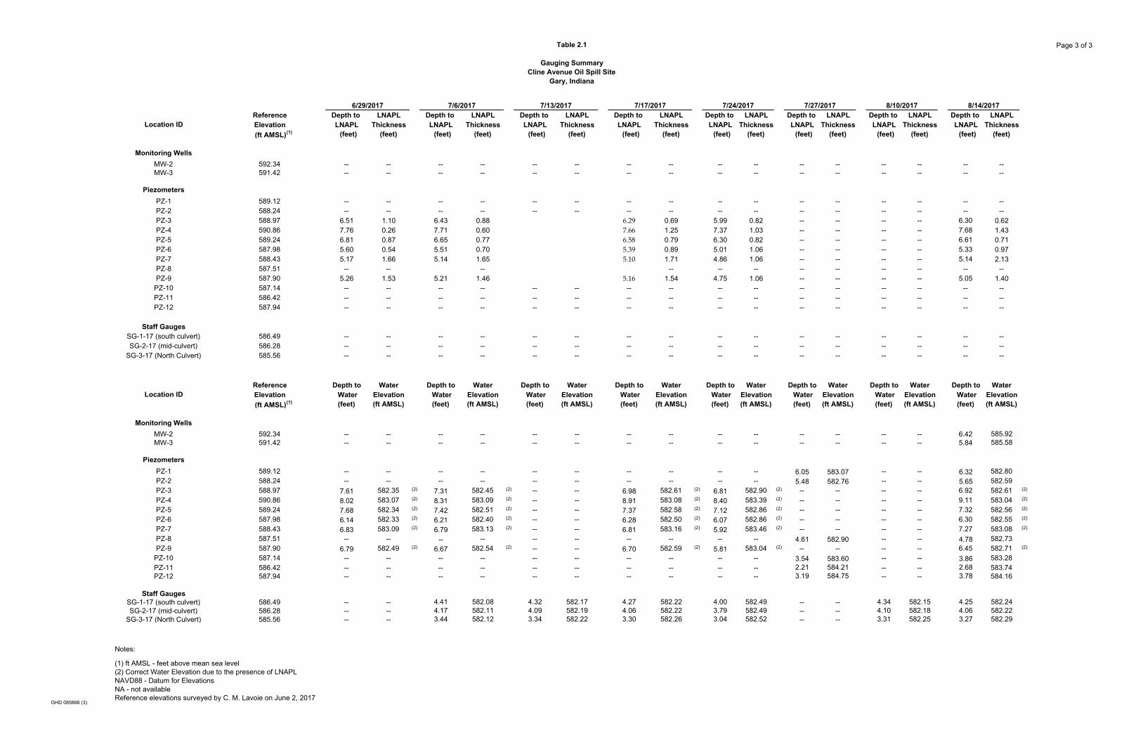
Table 2.1
Gauging Summary Cline Avenue Oil Spill Site
Gary, Indiana
Page 3 of 3
ReferenceLocation ID Elevation
(ft AMSL)(1)
Monitoring WellsMW-2 592.34MW-3 591.42
PiezometersPZ-1 589.12PZ-2 588.24PZ-3 588.97PZ-4 590.86PZ-5 589.24PZ-6 587.98PZ-7 588.43PZ-8 587.51PZ-9 587.90
PZ-10 587.14PZ-11 586.42PZ-12 587.94
Staff GaugesSG-1-17 (south culvert) 586.49SG-2-17 (mid-culvert) 586.28
SG-3-17 (North Culvert) 585.56
Notes:
(1) ft AMSL - feet above mean sea level(2) Correct Water Elevation due to the presence of LNAPLNAVD88 - Datum for ElevationsNA - not availableReference elevations surveyed by C. M. Lavoie on June 2, 2017
Depth to LNAPL Depth to LNAPL Depth to LNAPL Depth to LNAPL Depth to LNAPL Depth to LNAPL Depth to LNAPL Depth to LNAPLLNAPL Thickness LNAPL Thickness LNAPL Thickness LNAPL Thickness LNAPL Thickness LNAPL Thickness LNAPL Thickness LNAPL Thickness (feet) (feet) (feet) (feet) (feet) (feet) (feet) (feet) (feet) (feet) (feet) (feet) (feet) (feet) (feet) (feet)
-- -- -- -- -- -- -- -- -- -- -- -- -- -- -- ---- -- -- -- -- -- -- -- -- -- -- -- -- -- -- --
-- -- -- -- -- -- -- -- -- -- -- -- -- -- -- ---- -- -- -- -- -- -- -- -- -- -- -- -- -- -- --
6.51 1.10 6.43 0.88 6.29 0.69 5.99 0.82 -- -- -- -- 6.30 0.627.76 0.26 7.71 0.60 7.66 1.25 7.37 1.03 -- -- -- -- 7.68 1.436.81 0.87 6.65 0.77 6.58 0.79 6.30 0.82 -- -- -- -- 6.61 0.715.60 0.54 5.51 0.70 5.39 0.89 5.01 1.06 -- -- -- -- 5.33 0.975.17 1.66 5.14 1.65 5.10 1.71 4.86 1.06 -- -- -- -- 5.14 2.13
-- -- -- -- -- -- -- -- -- -- -- --5.26 1.53 5.21 1.46 5.16 1.54 4.75 1.06 -- -- -- -- 5.05 1.40
-- -- -- -- -- -- -- -- -- -- -- -- -- -- -- ---- -- -- -- -- -- -- -- -- -- -- -- -- -- -- ---- -- -- -- -- -- -- -- -- -- -- -- -- -- -- --
-- -- -- -- -- -- -- -- -- -- -- -- -- -- -- ---- -- -- -- -- -- -- -- -- -- -- -- -- -- -- ---- -- -- -- -- -- -- -- -- -- -- -- -- -- -- --
Depth to Water Depth to Water Depth to Water Depth to Water Depth to Water Depth to Water Depth to Water Depth to Water Water Elevation Water Elevation Water Elevation Water Elevation Water Elevation Water Elevation Water Elevation Water Elevation(feet) (ft AMSL) (feet) (ft AMSL) (feet) (ft AMSL) (feet) (ft AMSL) (feet) (ft AMSL) (feet) (ft AMSL) (feet) (ft AMSL) (feet) (ft AMSL)
-- -- -- -- -- -- -- -- -- -- -- -- -- -- 6.42 585.92-- -- -- -- -- -- -- -- -- -- -- -- -- -- 5.84 585.58
-- -- -- -- -- -- -- -- -- -- 6.05 583.07 -- -- 6.32 582.80-- -- -- -- -- -- -- -- -- -- 5.48 582.76 -- -- 5.65 582.59
7.61 582.35 (2) 7.31 582.45 (2) -- -- 6.98 582.61 (2) 6.81 582.90 (2) -- -- -- -- 6.92 582.61 (2)
8.02 583.07 (2) 8.31 583.09 (2) -- -- 8.91 583.08 (2) 8.40 583.39 (2) -- -- -- -- 9.11 583.04 (2)
7.68 582.34 (2) 7.42 582.51 (2) -- -- 7.37 582.58 (2) 7.12 582.86 (2) -- -- -- -- 7.32 582.56 (2)
6.14 582.33 (2) 6.21 582.40 (2) -- -- 6.28 582.50 (2) 6.07 582.86 (2) -- -- -- -- 6.30 582.55 (2)
6.83 583.09 (2) 6.79 583.13 (2) -- -- 6.81 583.16 (2) 5.92 583.46 (2) -- -- -- -- 7.27 583.08 (2)
-- -- -- -- -- -- -- -- -- -- 4.61 582.90 -- -- 4.78 582.736.79 582.49 (2) 6.67 582.54 (2) -- -- 6.70 582.59 (2) 5.81 583.04 (2) -- -- -- -- 6.45 582.71 (2)
-- -- -- -- -- -- -- -- -- -- 3.54 583.60 -- -- 3.86 583.28-- -- -- -- -- -- -- -- -- -- 2.21 584.21 -- -- 2.68 583.74-- -- -- -- -- -- -- -- -- -- 3.19 584.75 -- -- 3.78 584.16
-- -- 4.41 582.08 4.32 582.17 4.27 582.22 4.00 582.49 -- -- 4.34 582.15 4.25 582.24-- -- 4.17 582.11 4.09 582.19 4.06 582.22 3.79 582.49 -- -- 4.10 582.18 4.06 582.22-- -- 3.44 582.12 3.34 582.22 3.30 582.26 3.04 582.52 -- -- 3.31 582.25 3.27 582.29
8/14/20177/13/2017 8/10/20176/29/2017 7/6/2017 7/17/2017 7/27/20177/24/2017
GHD 085886 (3)