Embed Size (px)
Citation preview
THE UNIVERSITY OF NORTH CAROLINA AT WILMINGTON
601 SOUTH COLLEGE ROAD WILMINGTON, NORTH CAROLINA 28403-5910---910-962-7450---FAX 910-962-4014
DESIGN GUIDELINES
Architectural & Construction Services
Issued September, 2017
THE UNIVERSITY OF NORTH CAROLINA AT WILMINGTON
Introduction The guidelines have been prepared to guide and assist architectural and engineering consultants, contractors and university personnel with the planning, construction and renovation process as applied to university owned facilities. They provide guidance pertaining to the university’s established preferences and standards in the design and construction process, and standards for design and specification of materials, systems and components of facilities and procedures that should be followed in performing work for the university. These guidelines are expected to be followed as a general rule. We realize that each construction and renovation project is unique and may require an occasional deviation from these guidelines. In such cases, the appropriate recommendation or request for deviation from these guidelines should be presented to the university project manager for approval prior to any execution of the deviation. These guidelines are intended to be a living document that will be updated / modified as changes in technology and practices warrant. To this end, we welcome any comments and recommendations from users pertaining to these guidelines. Rachel Patrick Director of Architectural and Construction Services

Table of Contents This document is a guideline and cannot be used as a final specification
Issue September 2017 Page 1 of 4
Table of Contents UNCW General Design Guidelines UNCW Original Campus Construction Drawings UNCW Space Allocation Policy 01 00 10 Owner Representatives 01 00 20 Project Summary Checklist 01 00 30 Agency Review 01 00 40 Construction Detail Schedule 01 00 50 Room Numbering 01 00 60 Sustainable Design 01 00 70 Environmental and Safety 01 00 75 Construction Sign 01 00 80 Digging and Excavation 01 00 90 UNCW Supplementary General Conditions 01 10 10 CAD Standards 01 10 15 Specification Standards 04 00 00 Masonry General Requirements 05 50 00 Metal Fabrications 05 73 00 Decorative Metal Railings 06 00 00 Wood and Carpentry General Requirements 06 64 00 Plastic Panels 07 00 00 Thermal and Moisture General Requirements 07 31 00 Moderate Slope Roofing 07 50 00 Low Slope Roofing 07 53 80 Fall Protection 07 62 00 Sheet Metal Flashing and Trim 07 92 00 Joint Sealants 08 00 00 Doors – General Guidelines 08 11 13 Hollow Metal Doors and Frames

Table of Contents This document is a guideline and cannot be used as a final specification
Issue September 2017 Page 2 of 4
08 14 16 Flush Wood Doors 08 16 16 Acrylic Modified Polyester Doors (FRP) 08 51 13 Aluminum Windows 08 71 00 Door Hardware 09 00 00 Finishes General Requirements 09 29 00 Gypsum Wall Board 09 29 50 Polymer Modified GFRC 09 51 23 Acoustical Panel Ceiling 09 65 00 Resilient Flooring 09 66 23 Resinous Matrix Terrazzo Flooring 09 86 00 Carpeting 09 91 20 Painting 10 11 00 Visual Display Surfaces 10 14 00 Interior and Exterior Signage 10 21 13 Toilet and Shower Compartments 11 00 00 Equipment General Requirements 11 52 26 Projection Screens 12 21 13 Horizontal Louver Blinds 12 24 13 Roller Window Shades (Black-out Shades) 12 93 00 Site Furnishings 21 10 00 UNCW Standards for Fire Sprinkler System Design & Installation 22 00 00 General Plumbing
• 22 05 13 Common Motor Requirements for Plumbing Equipment
• 22 05 19 Meters and Gages for Plumbing Equipment
• 22 05 53 Identification for Plumbing Piping and Equipment
• 22 11 16 Domestic Water Piping
• 22 11 23 Domestic Water Pumps
• 22 13 16 Sanitary Waste and Vent Piping
• 22 13 19 Sanitary Waste Piping Specialties

Table of Contents This document is a guideline and cannot be used as a final specification
Issue September 2017 Page 3 of 4
• 22 14 13 Facility Storm Drainage Piping
• 22 42 00 Commercial Plumbing Fixtures 23 00 00 General Mechanical:
• 23 05 13 Common Motor Requirements for Mechanical Equipment
• 23 05 16 Expansion Fittings and Loops for HVAC Piping
• 23 05 19 Meters and Gauges for HVAC Piping
• 23 05 23 General Duty Valves for HVAC Piping
• 23 05 53 Identification for HVAC Piping and Equipment
• 23 05 93 Testing, Adjusting and Balancing for HVAC
• 23 07 16 HVAC Equipment Insulation
• 23 07 19 HVAC Piping Insulation
• 23 09 00 Instrumentation and Control for HVAC
• 23 09 93 Sequence of Operation for HVAC Controls
• 23 11 23 Facility Natural Gas Piping
• 23 21 13 Hydronic Piping
• 23 21 23 Hydronic Pumps
• 23 23 00 Refrigerant Piping
• 23 25 00 HVAC Water Treatment
• 23 31 13 Metal Ducts
• 23 31 19 HVAC Casings
• 23 36 00 Air Terminal Units
• 23 37 13 Diffusers, Registers and Grilles
• 23 41 33 High Efficiency Particulate Filtration
• 23 52 16 Condensing Boilers
• 23 63 13 Air-Cooled Condensers
• 23 64 16 Centrifugal Water Chillers
• 23 64 19 Reciprocating Water Chillers
• 23 65 00 Cooling Towers
• 23 73 13 Modular Indoor Central-Station Air Handling Units

Table of Contents This document is a guideline and cannot be used as a final specification
Issue September 2017 Page 4 of 4
• 23 74 33 Dedicated Outdoor-Air Units
• 23 81 26 Split System Air-Conditioners
• 23 82 16 Air Coils
• 23 82 19 Fan Coil Units
• 23 82 23 Unit Ventilators
• 23 82 39 Unit Heaters 26 01 00 Electrical General:
• 26 05 33 Conduit
• 26 08 00 Electrical Testing
• 26 12 19 Pad Mounted Distribution Transformers
• 26 18 00 Air Interrupter Switch
• 26 22 00 Dry Type Transformers
• 26 24 16 Panelboards
• 26 27 26 Wiring Devices
• 26 29 23 Variable Frequency Controllers
• 26 32 13 Packaged Engine Generators Systems
• 26 51 00 Interior Luminaires (Includes Emergency Lighting)
• 26 56 00 Site And Exterior Lighting 26 99 99 Section 26 00 00 Appendix 27 00 00 ITSD’s Classroom Recommendations and Technology Baseline 27 05 00 UNCW Telecommunications Standards 28 13 00 UNCW Standards for Installation of Access Control Equipment 28 16 00 UNCW Guidelines for the Installation of Intrusion/Burglary Systems 28 23 00 UNCW Standards for Installation of Cameras and Camera Systems 28 31 11 UNCW Standards for Fire Alarm System Design 28 31 13 Fire & Security Alarm Systems 32 00 00 Exterior Improvements 32 12 16 Asphalt Paving 32 90 00 UNCW Landscaping Standards

UNCW General Design Guidelines This document is a guideline and cannot be used as a final
specification
Issue September 2017 Page 1 of 12
UNCW General Design Guidelines
Part 1: General
1.01 All UNCW Buildings are owned by the State of North Carolina and are entrusted to UNCW.
1.02 These standards apply to all UNCW buildings irrespective of the funding source.
1.03 Exceptions to this guideline can be made only with the written approval of the UNCW Architectural and Construction Services.
1.04 New buildings at UNCW should meet the SCO standards for 75-year construction.
Part 2: General Exterior - Architectural
2.01 The UNCW Board of Trustees has mandated that the design of the Main Campus is to be Georgian-Style. There are to be no exceptions to this policy.
2.02 In order to carry out this mandate of the UNCW Board of Trustees, the architect should reference the original UNCW campus construction drawings which includes the following buildings: Alderman Hall, James Hall, Hoggard Hall, Kenan Hall, and Kenan Auditorium for design and especially for the exterior details of the buildings. The architect should bear in mind that the original campus was designed by the master of the classical-style building, Leslie Boney, and should be the source of ongoing design at UNCW. A. Reference Material:
1. The original UNCW campus construction documents, which are included as an attachment to this section. See “UNCW Original Campus Construction Documents”.
2. “The Four Books of Architecture” by Andrea Palladio.
2.03 Columns & Pilasters: A. Exterior columns at major entrance porticos with no exceptions are to be Temple of the
Winds – fluted. B. Exterior pilasters at major entrance porticos with no exceptions are to be Temple of the
Winds – rectangular - fluted. C. Exterior columns on minor porches are to be Doric style – fluted. D. Exterior pilasters on minor porches are to be Doric style – rectangular – fluted.
2.04 Roofs: A. Buildings are to have hip roof – not gabled roofs.
1. See sections 07 31 00 Moderate Slope Roofing and 07 50 00 Low Slope Roofing.

UNCW General Design Guidelines This document is a guideline and cannot be used as a final
specification
Issue September 2017 Page 2 of 12
B. Roof slopes are to be the same ratio as Alderman Hall, 6:12. (See original drawing sht. 25.) C. Flat roofs are not allowed on UNCW Main Campus except in a limited way on secondary
entrances porches or as designated by the UNCW Architectural and Construction Services in certain renovation project or additions to existing UNCW buildings.
D. Pediments at entrances or on major columned porches are to have the same slope, detail, and design as Alderman Hall.
E. Roof terraces, gardens, living roofs, etc. are not allowed. F. Balconies and elevated terraces or patios are not allowed. G. Dormer windows or ventilators are not allowed. H. Skylights are not allowed. I. Gutters and Downspouts:
1. No hidden gutters allowed. 2. Downspouts are to connect into the stormwater drainage system and are not to be
discharged onto the ground unless there is a strict requirement to do so from SCO. 3. Color: Match the color of downspouts at Hoggard Hall. 4. See sections 05 50 00 Metal Fabrications and 07 62 00 Sheet Metal Flashing & Trim
2.05 Windows: A. Windows should follow the UNCW Georgian – divided light style. B. Large plate glass windows with aluminum, storefront frames are not allowed unless
specifically authorized by the UNCW Architectural and Construction Services. C. Windows shall be fixed. Operable windows are not allowed.
1. See section 08 51 13 Aluminum Windows D. Window sills are to precast concrete and are to be the same design as the window sills for
Alderman Hall. E. The window sill height is to be 3’-4” from the floor.
2.06 Exterior Materials: A. No wood is allowed on the exterior of any building, ancillary building, or mechanical and
electrical enclosures. This includes doors, gates, louvers, window trim, door frames, and trim, etc.
B. All exterior trim to include cornices, columns, pilasters, door frames for main entrance doors with no exceptions are to be GFRC (Glass Fiber Reinforced Concrete) with a painted finish. (See section 09 29 50 Polymer Modified GFRC).
C. Exterior doors are to be FRP or Aluminum with continuous hinges. See section 08 16 16. 1. Exterior utility doors may be hollow metal if out of public view. See section 08 11 13.

UNCW General Design Guidelines This document is a guideline and cannot be used as a final
specification
Issue September 2017 Page 3 of 12
2.07 Brickwork: A. The brick for new buildings is to be Statesville Brick Company – Red Royal Special. It is to
be a modular brick. The bond for the brick is a running bond with a raked joint. The mortar color is light grey. See section 04 00 00 Masonry.
B. Additions to existing buildings should match the brick, mortar color, etc. of the existing building.
C. Quoins are to be the same design as Alderman Hall. D. Jack arches are to be the same design as Alderman Hall. E. Brick veneer expansion joint sealant to match brick color. (See 07 92 00 Joint Sealants)
2.08 Building Construction: A. Buildings are to have a steel structure unless the design loads prove otherwise. B. Wood framed buildings are not allowed without the written approval of the UNCW
Architectural and Construction Services. C. Exterior walls are to be a metal stud with a brick veneer.
1. Provide Moisture and Mold Resistant gypsum board on the interior side. D. Buildings are to be slab on grade with the First-Floor elevation to be 2’-6” above the final site
elevations. E. A crawl space is not allowed. F. The floor-to-floor height of a building is to be 16’-0” for general classroom-office building
but can be increased with the approval of the UNCW Architectural and Construction Services for wet laboratory buildings to meet ventilation requirements.
2.09 Exterior Mechanical and Electrical Accessories and Equipment: A. Laboratory exhaust should be disguised in buildings as chimneys.
2.10 Other Exterior Items: A. Exterior handrails are to be the same design as the Alderman Hall exterior handrail. B. Exterior risers and runs are to be precast with the same design as Alderman Hall main
entrance steps. C. Entrance porches are to have slate flooring. D. See UNCW Original Campus Construction Documents.
Part 3: Exterior Building Signage – UNCW Main Campus
3.01 The name of the building is to be mounted in the cornice on all sides of the building or as determined by the UNCW Architectural and Construction Services.

UNCW General Design Guidelines This document is a guideline and cannot be used as a final
specification
Issue September 2017 Page 4 of 12
3.02 UNCW has a standard for building lettering. (See Section 10 14 00 Signage). This standard must be followed with no exceptions. The letters should be specified by the architect so that there is a stand-off for mounting the letters away from the cornice. A. The color of the letters on a white background is bronze. B. If letters must be mounted on brick, the color is to be white.
3.03 The name of the building will be provided to the consultant by the UNCW Architectural and Construction Services.
Part 4: Exterior - UNCW CMS Campus
4.01 New buildings or additions to the existing buildings are to follow the form of the original CMS building.
4.02 The buildings are to have flat roofs. (Less than 3:12 pitch)
4.03 The brick and mortar are to match the brick and mortar of the original CMS building.
4.04 Exterior trim is to match the original CMS building.
Part 5: Interior – Main Campus and CMS
5.01 Generally, all interior walls are to be painted.
5.02 The ceiling grid is to be 2’x2’. The grid rail is to be 15/16 inch in width. The color of the ceiling tile is white.
5.03 All exterior windows are to have Venetian blinds. The color of the blind is white.
5.04 Rooms that require black-out shades are to also have Venetian blinds on the exterior side of the blind/shade assembly.
5.05 Built-in casework is to be very limited in the building, durable and shall be vetted during the design process.
5.06 Lighting: A. Generally, the designer should rely on a standard 2 x 4 parabolic fixtures unless otherwise
noted. The fixture should have two light levels. 1. Classrooms and Seminar rooms shall have Direct-Indirect type fixtures. 2. Direct-Indirect type fixtures as an Add Alternate:

UNCW General Design Guidelines This document is a guideline and cannot be used as a final
specification
Issue September 2017 Page 5 of 12
a. Designers shall specify the use of Direct-Indirect type fixtures in place of parabolic fixtures in all occupiable spaces in building as an Add Alternate cost. Corridors included. Verify included spaces during Design Development review.
B. Pendant lighting is allowed as approved. Not generally recommended. C. Track lighting, recessed can lighting, etc., is limited to the building lobby.
5.07 Buildings should have separate rooms for recycling (each floor), general receiving, mail delivery to the building, and vending. All these rooms should have lockable doors.
5.08 HAZMAT rooms and external storage requirements should be determined on a building by building basis with UNCW EH&S.
5.09 Vending rooms, mail rooms, storage rooms, etc. should be designed so that they can be converted into programmed for other functions to provide increased flexibility for future space requirements.
Part 6: Interior – Walls
6.01 Walls at the exterior perimeter of the building and walls around wet areas such as rest rooms are to have mold and moisture resistant fiberglass gypsum board. (See section 09 29 00 Gypsum Wall Board)
6.02 Interior walls at the following locations should go to structure: rest rooms, fire stairs, vending rooms, classrooms, lobbies, corridors, conference rooms, seminar rooms, distance learning classrooms, laboratories, lecture halls, and janitorial, telecom, security, and audio-visual closets.
6.03 Generally, the exception is the wall between faculty and staff offices, and office support spaces such as file rooms, storage rooms, mail rooms, recycling rooms, etc. Those walls should extend 12” above the ceiling unless there is a requirement for sound security or rating requirement then the walls should be extended to structure.
6.04 Block walls are not required around core rest rooms.
6.05 Dividing walls between classrooms, seminar rooms, distance learning classrooms, and lecture halls should have sound attenuating gypsum board.
6.06 All walls should have sound insulation that is continuous from floor to top of wall.

UNCW General Design Guidelines This document is a guideline and cannot be used as a final
specification
Issue September 2017 Page 6 of 12
Part 7: Interior – Main Campus
7.01 Building Lobbies A. The building lobby should have a higher standard of finish the rest of the building. B. Multiple level lobbies and atriums are not allowed without the permission of the UNCW
Architectural and Construction Services. C. The building lobby should be designed as a Georgian style room with classical trim to include
the cornice, pilasters, moldings, wainscoting, and baseboards. D. A hard-finished ceiling is allowed in the lobby design as long as a system can be devised to
provide a clear, accessible routing path for utilities above the ceiling such as telecom wiring, security wiring, etc.
E. Pendant lighting is not allowed. F. Specialty lighting, such as recessed can lighting, is allowed. G. The flooring should be epoxy terrazzo with a classical design to imitate marble or granite
flooring. (See section 09 66 23 Resinous Matrix Terrazzo Flooring.) H. Elevators, rest rooms, service closets, etc. should not open directly into the main building
lobby but should be in a separate but immediately accessible area. I. See the UNCW Teaching Laboratory (Psychology Building) for an example of an approved
lobby design.
7.02 Corridors: A. Floor: Vinyl tile. B. Walls: Painted. C. Ceiling: 2 x 2 lay-in acoustical tile D. Base: Vinyl. E. Door frames: Painted steel. F. Doors: Solid core with wood (maple) laminate veneer with a clear finish.
1. Provide view windows at passage doors within corridors and doors into stairs. G. Lighting: 2 x 4 lay-in fixture
7.03 Staff and Faculty Offices A. Floor: Carpet. B. Walls: Painted. C. Ceiling: 2 x 2 lay-in acoustical tile D. Base: Vinyl.

UNCW General Design Guidelines This document is a guideline and cannot be used as a final
specification
Issue September 2017 Page 7 of 12
E. Door frames: Painted steel. F. Doors: Solid core with wood (maple) laminate veneer with a clear finish. No view window. G. Lighting: 2 x 4 lay-in fixture.
7.04 Office Support Spaces – Storage, Mail, File, Photocopy, Kitchens, etc. A. Floor: Vinyl tile. B. Walls: Painted. C. Ceiling: 2 x 2 lay-in acoustical tile D. Base: Vinyl. E. Door frames: Painted steel. F. Doors: Solid core with wood (maple) laminate veneer with a clear finish. No view window. G. Lighting: 2 x 4 lay-in fixture – dual level lighting.
Part 8: General Classrooms and Seminar Rooms
A. Floor: Vinyl tile. B. Walls: Painted. C. Ceiling: 2 x 2 lay-in. D. Base: Vinyl. E. Door frames: Painted steel. F. Doors: Solid core with wood (maple) laminate veneer with a clear finish. No view window. G. Lighting: 2 x 4 lay-in fixture – dual level lighting. H. Unless there is a fixed projection screen, classrooms are to have a motorized, retractable
screen located above the ceiling. (See 11 52 26 Projection Screens) 1. See section 27 00 00 ITSD Classroom Recommendations and Technology Baseline.
I. Classrooms are to have white boards and tack boards. (See 10 11 00 Visual Display Surfaces) 1. See section 27 00 00 ITSD Classroom Recommendations and Technology Baseline.
8.02 Tiered Classrooms, Conference Rooms, Distance Learning Classrooms, Lecture Halls, and Multipurpose Rooms: A. Floor: Carpet. B. Walls: Painted. C. Ceiling: 2 x 2 lay-in acoustical tile D. Base: Vinyl. E. Door frames: Painted steel.

UNCW General Design Guidelines This document is a guideline and cannot be used as a final
specification
Issue September 2017 Page 8 of 12
F. Doors: Solid core with wood (maple) laminate veneer with a clear finish. No view window. G. Lighting. 2 x 4 lay-in fixture. H. Widows are to have manual blackout shade on the interior (between jambs) with Venetian
blinds on the outside of the window (wall mounted). 1. See section 12 24 13 Roller Window Shades for block-out shades. 2. See section 12 21 13 Horizontal Louver blinds for venetian blinds.
I. Floor outlets for electrical and communications are allowed in conference rooms with a fixed table.
J. Multipurpose rooms are to have adjacent furniture storage closets preferably with doors opening into the room and not the corridor.
K. Unless there is a fixed projection screen, classrooms are to have a motorized, retractable screen located above the ceiling. (See section 11 52 26 Projection Screens) 1. See section 27 00 00 ITSD Classroom Recommendations and Technology Baseline.
L. Classrooms are to have white boards and tack boards. (See 10 11 00 Visual Display Surfaces) 1. See section 27 00 00 ITSD Classroom Recommendations and Technology Baseline.
M. Private conference rooms (a conference room that is only accessible through a lockable, private office) are not allowed.
8.03 Mechanical Rooms: A. Mechanical rooms on the ground floor are to have painted walls and a sealed floor. B. Mechanical rooms on upper floors of the building are to have a continuous curb running
around the perimeter of the space with a continuous, waterproof membrane. C. Floor drains are required in all mechanical rooms.
8.04 Rest Rooms, Showers Rooms, Locker Rooms A. Rest rooms are to be grouped into a central core near the main entrance to the building with
the elevators, janitorial closets, electrical closets, etc. B. Separate faculty or private rest rooms are typically not allowed. If it is required by LEED,
then a shower-dressing room component can be added to each of the core rest rooms. C. Rest Rooms are to have ceramic tile floors and ceramic mosaic tile behind wet areas.
1. The remaining walls in rest rooms are to be painted with latex.
8.05 Custodial Closets A. The following requirements apply to the design of custodial closets. In general, one custodial
closet shall be provided for each 20, 000 gross square feet of building floor space, but not less than one per floor. The minimum size shall be eighty square feet. No dimension of the room shall be less than six feet. These rooms shall not be used for passageways, pipe or duct chases, electrical panels telephone equipment, mechanical equipment or elevator controls. Each custodial room shall contain the following:

UNCW General Design Guidelines This document is a guideline and cannot be used as a final
specification
Issue September 2017 Page 9 of 12
1. A recessed mop receptor with curb vice a service sink. The mop receptor shall be located in one corner space beside the entrance. It is to be ceramic tile; the remainder of the floor may be trowel finished concrete or V.A.T. A waterproof membrane must be provided underneath the entire floor. The entire floor must slope toward the mop receptor.
2. Hot and cold outlets/faucets, not less than 24 inches above the floor receptor and provided with hose bibs, siphon breaker devices and bucket hooks on the hose bibs.
3. Pegs for rotary brush storage, hangars and wall space for dust mops and brooms, and hangars for wet mops above the floor receptors. Wet mop hangars shall allow the mops to hang with the mop portion down.
4. A minimum of 24 square feet of shelving, minimum depth of 24 inches to be used for the storage of maintenance supplies and equipment. Shelving shall be adequately secured to the wall. Wood shelves are prohibited.
5. Positive ventilation provided by an exhaust fan to accommodate charging of cleaning equipment batteries, drying of mops, etc.
6. Recessed or guard protected light fixtures. 7. A minimum of one 120-volt grounded AC electric duplex receptacle located on open wall
space, near the light switch. 8. A door at least 36 inches in width, preferably opening outward. 9. Floor space for large floor machines. 10. Hard wall surfaces. 11. A storage slot for a ladder, preferably at the end of the shelving.
B. Custodial closets should be centrally located and not at the end of dead end corridors, on a stair landing nor inside another room, under stairways or in a narrow space.
C. Custodial closets should be located as close as possible to the receiving entrance and elevator. The design must accommodate their use as wash rooms, storage rooms, lockers and lunch rooms for custodians.
8.06 Storage Rooms: A. Every building of 40,000 gross square feet or larger shall have a storage room of at least 200
square feet for custodial supplies and equipment. It should be located near the elevator. 1. Shelves having minimum depth of 12 inches shall be provided on at least one wall. 2. The entry door shall be at least 36 inches in width.
8.07 Stairs - General A. Provide handrails on both sides of stairs.
8.08 Stairs – Enclosed Fire Stairs A. Walls, if gypsum board, provide impact-rated type. (See section 09 29 00 Gypsum Board) B. Doors shall be provided with vision panels.

UNCW General Design Guidelines This document is a guideline and cannot be used as a final
specification
Issue September 2017 Page 10 of 12
8.09 Kitchens A. Walls: FRP panels B. Floor & Base: (Reserved) C. Base: (Reserved) D. Ceiling: 2x2 Lay-in FRP faced tiles. Coordinate with Health Dept. requirements.
8.10 Section references for items noted in part 8. A. All sections should be reviewed for additional design guidance. B. The following sections provide additional information mentioned in Part 8.
1. 06 00 00 Wood and Carpentry 2. 08 00 00 Doors – General Guidelines 3. 08 11 13 Hollow Metal Doors and Frames 4. 08 14 16 Flush Wood Doors. 5. 08 16 16 FRP Doors 6. 09 00 00 Finishes 7. 09 29 00 Gypsum Wall Board
Part 9: Energy Conservation
9.01 Energy conservation must be an essential part of design and development for all new construction and renovation projects. In addition to basic conservation requirements established by the State of North Carolina, design development should consider the utilization of passive solar techniques as part of the design development process. The consideration of non-conventional and renewable energy sources should be considered. A. See section 01 00 70 Sustainability
Part 10: Utilities Dig Permit
10.01 The specific University procedures for obtaining a Dig Permit (See 01 00 80) shall be followed prior to any penetration of the ground. In addition, the Utility Locator Service shall be contacted. There exists on University property a large variety and amount of both University and Public underground utilities/infrastructure. The Contractor shall be responsible for all damaged utilities. The procedures for University Dig Permits shall be incorporated into the project specifications by the Architect/Engineer. A. See section 01 00 80 Digging and Excavation
Part 11: Underground Utilities Marking

UNCW General Design Guidelines This document is a guideline and cannot be used as a final
specification
Issue September 2017 Page 11 of 12
11.01 All underground utility systems, lines, etc. are to be marked with foil warning tape or conductor for traceability.
Part 12: Standard Stock Items
12.01 Designers are directed and required to base their designs upon standard stock items whenever possible. Where custom-built items are required, the Designers shall clearly state this fact and attain the approval of the Office of Facilities before proceeding to the construction drawing phase of design.
Part 13: Recruitment and Selection of Historically Underutilized Businesses
13.01 The University intends to do everything legal, proper and reasonable to achieve a goal of at least ten percent for participation by minority businesses in each campus construction project. Many of the University’s responsibilities in this effort are transferred to the Designer in the design contract, and in addition, the Designer is expected to do everything practical to assure that the prime contractor(s) responsibilities are fulfilled. A. The Designer’s responsibilities in this regard are established by the State Construction Office
at the time the design contract is negotiated. However, guidelines and standards in this regard can change frequently, and the Designer must, therefore, be sure that he/she is fully abreast of all of the current requirements. 1. See also section 01 00 30 Agency Review
Part 14: Cleanup Activities
14.01 The project site shall be kept in a good state of cleanliness. Rubbish and trash cleanup shall be accomplished daily. Contractor shall ensure that debris is not blowing off site onto the surrounding campus areas. Use of University dumpsters for contractor trash is not permitted.
Part 15: Construction Fences
15.01 Design shall include and the Contractor shall provide and maintain a fence around the construction site to discourage unauthorized entry. The fence shall follow the limits shown on the drawings and such additional area as may be required for the storage of material when agreed upon by the Designer and the University. The fence shall be no less than six feet high. The fence shall be constructed prior to the beginning of on-site construction operations, and shall not be removed until the beginning of finish grading and after the building is secure from unauthorized entry.

UNCW General Design Guidelines This document is a guideline and cannot be used as a final
specification
Issue September 2017 Page 12 of 12
Part 16: Temporary Utilities
16.01 Temporary or permanent connections to existing utility systems by the Electrical, HVAC, and Plumbing Contractors must be approved by the Physical Plant Department as to location, manner, and scheduling of such connections. Approval should be coordinated through the Project Manager. Where such connections require shutdown of existing systems or facilities, the shutdown will be made by University personnel at a time agreed upon by the Physical Plant Department and the affected University personnel/Client as being suitable for ongoing operations of the University. Written request for a shutdown must be made to the Physical Plant Department via the Project Manager at least three weeks in advance. Immediately after the shutdown reinstatement of normal service will be made by Physical Plant Department personnel.
16.02 When temporary service lines are no longer required they shall be removed by the Contractor.
16.03 Any part or parts of permanent service lines, grounds, and buildings disturbed or damaged by the installation and/or removal of the temporary service lines shall be restored to their original condition by the Contractor.
Part 17: Sanitary Facilities
17.01 The Contractor shall provide, operate and maintain in a clean and sanitary condition adequate sanitary facilities. The use of self-contained portable units will be permitted. Open pit sanitary facilities will not be permitted. Sanitary facilities will not be provided by the University nor may University facilities be used by construction personnel.

UNCW Original Construction Drawings This document is a guideline and cannot be used as a final specification
Issue September 2017 Page 1 of 1
UNCW Original Campus Construction Drawings
Part 1: Reference Material
1.01 List attached drawings of the original campus built in 1960.
Dwg. Drawing Title Date Designer____ 1 Wilmington College Site Improvement 2/1/1960 Boney Architect 2 Foundation Plan / Storm Drainage 2/1/1960 Boney Architect 3 1st Floor & 2nd Floor Plan (Hoggard Hall) 2/1/1960 Boney Architect 4 1st Floor & Typical Elevation / Library Building 2/1/1960 Boney Architect 5 Elevation & Second Floor Plan (Library Building) 2/1/1960 Boney Architect 6 1st Floor Plan Assembly Building (Student) & Details 2/1/1960 Boney Architect 7 Room Finish Schedule & Window Schedule 2/1/1960 Boney Architect 8 Rear & Left Side Elevations 2/1/1960 Boney Architect 9 Front, Rear, And Right Side Elevations / Details 2/1/1960 Boney Architect 10 South-West, North-West, Front & Rear Elevations 2/1/1960 Boney Architect 11 Typical Exterior Wall & Details 2/1/1960 Boney Architect 12 Main Entrance Porch & Sections & Details 2/1/1960 Boney Architect 13 Section Thru Wall Under Porch/Typical Stone Details 2/1/1960 Boney Architect 14 Cupola Details, Elevations, Typical Window Details 2/1/1960 Boney Architect 15 Typical Wall Sections / Section Thru Front Terrace & Steps 2/1/1960 Boney Architect 16 Stairway Plan & Sections 2/1/1960 Boney Architect 17 Building Cross Sections & Water Proofing Details 2/1/1960 Boney Architect 18 Section Thru Library Building & Corridors Elevations 2/1/1960 Boney Architect 19 Corridors Elevations 2/1/1960 Boney Architect 20 Details & Elevations Of Academic Building 2/1/1960 Boney Architect 21 Chemistry Laboratory Plans & Details 2/1/1960 Boney Architect 22 Cabinet Details 2/1/1960 Boney Architect 23 Interior Elevations, Glazed Details, Kitchen Plan 2/1/1960 Boney Architect 24 Library Building Roof Framing Plan/Structural Framing Plan 2/1/1960 Boney Architect 25 Structural Details

UNCW Space Allocation Policy This document is a guideline and cannot be used as a final specification
Issue September 2017 Page 1 of 8
UNCW Space Allocation Policy
Part 1: Purpose
1.01 The facilities at the University of North Carolina Wilmington support the educational mission and strategic goals of the University. The University of North Carolina Wilmington's physical facilities, like its personnel and financial assets, are resources to be planned, managed, and maintained in a manner which most contributes to the University's mission. In any space assignment, ownership is not implied by occupancy, nor should it be inferred. Because of the finite nature of the physical plant, space management policies are needed to assure that the University fully maximizes its resources in providing top quality academic services to its students and a positive and productive working environment for its faculty and staff. The goal of space planning, management, and allocation is to make the best possible use of these physical assets and to plan for future needs.
Part 2: Scope
2.01 Applies to all university departments and divisions and covers all university space.
Part 3: Policy
3.01 The Principles of Space Planning below are interrelated and should be considered together. No single principle should take priority over others. A. All space is owned by the State of North Carolina. B. Allocation decisions are ultimately the Chancellor's responsibility. C. Space supporting academic activities, such as classrooms and research space, have priority
over space supporting administrative activities, such as offices. However, general classrooms are considered to be a University resource and should not be exempted from the space review process.
D. Synergistic or like activities should be adjacent or housed in close proximity. E. Space assignments that save money, enhance revenues, or encourage interdisciplinary
interaction will be given priority. F. Donor restrictions on space usage will be honored to the extent possible. Donor-restricted
facilities will be considered separately, but are not exempted from, the space review process or UNCW Space Standards.
G. Space allocations that satisfy long-range plans take precedence over more temporary accommodations.
H. Offices that require frequent access by students, faculty, or staff will be located centrally and conveniently whenever possible.
I. Periodic review of space should be made prior to leasing space; the leasing of off-campus facilities should be a last resort. Leasing should be considered only when unique

UNCW Space Allocation Policy This document is a guideline and cannot be used as a final specification
Issue September 2017 Page 2 of 8
circumstances, program needs, equipment requirements, or specific location have defined advantages that exceed University facilities.
J. Space assignments will be reviewed periodically to determine how well current usage serves a dynamic set of University needs and priorities. No permanent optimal space allocation can be achieved. Space allocation, planning, and management are ongoing processes.
Part 4: Procedure
4.01 The following procedures have been developed to provide information on where and how to make requests for space allocation and what the decision process entails. A. Renovation
1. Existing space must be accepted as is. 2. Given the cost of remodeling and moving, it is not practical to attempt to maintain optimal
space allocation at all times. Space should not be considered as available for reassignment, nor activities appropriate for moving, unless some minimum time commitment can be made; at least two years’ occupancy if possible. Exceptions might include displacement while space is renovated, brought up to code, or corrections to safety concerns are implemented.
3. Renovations and new construction are to follow the UNCW Space Guidelines (See Appendix B).
B. Approval Process 1. A University Space Committee, chaired by the UNCW Space Coordinator, will be formed
to handle the process of space allocation and reallocation. (See Appendix A - University Space Committee Organization Chart.)
2. The University Space Committee will be comprised of administrative staff from each of the major divisions.
3. The University Space Committee will meet regularly, optimally once per month, to review space requests. Recommendations from the University Space Committee will be submitted to the Provost and the Vice Chancellor for Business Affairs, or their designees, for approval.
4. The Provost and Vice Chancellor for Business Affairs, or their designees, will forward their space recommendations to the Chancellor, or a designee, for final approval.
C. Request Requirements 1. Requests for new or changed space must be submitted in written form to the University
Space Committee at least three months prior to the actual space being needed. 2. Requests must include an internal space audit that verifies that adequate space does not
exist within the resources already available to the college, school, program, or department. This audit must be rigorous and must include shared space, storage space, etc. If help is required to complete the audit, contact the University Space Coordinator.
3. Justification for the space requested must accompany the audit. It must include information about the existing, new, or expanded program that requires the space; the

UNCW Space Allocation Policy This document is a guideline and cannot be used as a final specification
Issue September 2017 Page 3 of 8
schedule; whether the requested space is temporary or permanent; and funding for any additional space.
4. All requests will be considered within the context of the Space Planning and Management Policy and its principles by the University Space Committee. The Committee will inform and collaborate with the Provost and Vice Chancellor for Business Affairs in considering requests.
5. Requests will be acknowledged in writing or by email upon receipt. 6. When possible, small space adjustments, typically 500 sq. ft. or less, will be handled in an
expedited manner. 7. Where possible, departments will be allowed to allocate space based on seniority. 8. While classrooms are a campus wide resource, classroom, seminar room, teaching
laboratory, etc. scheduling will offer priority to departments located proximate to the space.
9. The policy for the campus is not to build or provide private conference rooms that only open into a private office. Conference rooms must open only onto a public corridor for optimal access to all users. Space requests for private conference rooms will be denied.
10. Similarly, the policy of the campus is not to provide private bathrooms, showers, or dressing rooms or faculty rest rooms in buildings. Space requests for these items will be denied.
11. Procedures for Conducting a Space Audit a. The following procedures have been developed to provide information on how to
develop a space audit for inclusion in a request for space allocation. b. A detailed inventory of the department or division's space may be requested from the
Office of the University Space Coordinator. This will include room use and the type of activity associated with the room as well as net square feet totals and occupants.
c. The department or division should perform a physical walk through of its space to verify space assignments and make sure all current space is being fully utilized.
d. If the department or division needs assistance in performing the space audit, they should contact the University Space Coordinator. That office can arrange for a physical review of the space.
e. Space requests and requests for space audits must have written approval from either the Provost, the appropriate vice-chancellor or from the Chancellor’s Chief of Staff prior to submitting the request to the University Space Coordinator for action.
f. Options such as the sharing of facilities or the reallocation of storage may be suggested as an alternative to the allocation of new space.
D. Analysis of Space Needs 1. Space needs will be analyzed by the University Space Committee, and throughout the
Approval Process, in the context of all of the following factors. These factors are not in a particular order of priority.
a. The Principles of Space Planning (listed above). b. The University Space Planning Standards (Appendix B).

UNCW Space Allocation Policy This document is a guideline and cannot be used as a final specification
Issue September 2017 Page 4 of 8
c. Ability of the unit to pay for the space d. Certain uses of space require specialized building systems. For example, computers
and laboratories have special air conditioning requirements. Efficient and combined use of resources, equipment, or systems should always be considered.
e. Similarly, building occupants may have specialized needs. For example, faculty requires support staff. It may be more cost-effective and make future reassignment of space easier if contiguous blocks of space are for the same purpose or program (e.g., a group of faculty offices with support staff space) or building systems are utilized to their appropriate capacity to serve the occupants.
E. Vice Chancellors, Deans, and Directors Responsibilities 1. Vice Chancellors, Deans, and Directors are responsible for managing the space occupied
by activities under their control, just as they are responsible for the management of staff and fiscal resources. Space administration may include redistributing, exchanging, or improving space.
F. Unused or Underutilized Space 1. Unused or underutilized space may not be stockpiled by a unit; nor may they allow
occupancy by another department. As colleges, schools, departments, and administrative units identify space in excess of current needs (either through program change, reduction, or redirection), they will relinquish such unused space back into the University's general space pool for reassignment. As space is returned for reassignment, the indirect costs associated with it will be assigned to the new occupant. When possible, space costs for mid-year adjustments in space assignments will be determined by the Office of the Vice Chancellor for Business Affairs.
2. Units may return unused space or request needed space on an ongoing basis. Inactive or underutilized space will be considered in the resolution of space needs. Although space may be returned whenever it is available, space surveys conducted by the University Space Coordinator will assist units in identifying unused or underutilized space. The renovation of vacated space and the construction of new buildings will be coordinated through the Associate Vice Chancellor for Business Affairs – Facilities.

UNCW Space Allocation Policy This document is a guideline and cannot be used as a final specification
Issue September 2017 Page 5 of 8
APPENDIX A
University Space Planning Administration
Chancellor
Executive Committee on Space
Space Planning & Allocation Committee
Space Planning & Management Office of Institutional Research & Planning
Office of the Chancellor
Business Affairs
Student Affairs
Academic Affairs
University Advancement
UNCW Space Allocation Policy This document is a guideline and cannot be used as a final specification
Issue September 2017 Page 6 of 8
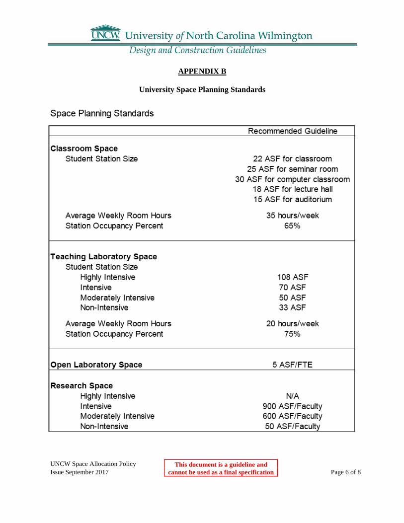
APPENDIX B
University Space Planning Standards

UNCW Space Allocation Policy This document is a guideline and cannot be used as a final specification
Issue September 2017 Page 7 of 8

UNCW Space Allocation Policy This document is a guideline and cannot be used as a final specification
Issue September 2017 Page 8 of 8

01 00 10 Owner Representatives This document is a guideline and cannot be used as a final specification
Issue September 2017 Page 1 of 1
01 00 10 Owner Representatives: The following general guidelines apply to all contracts between the University and Architects, Engineers and Contractors: Design: During the Design process the assigned Facilities Planning and Design Section PROJECT MANAGER is the sole University contact for all questions and communication with the University regarding all matters concerning the project. He/she coordinates all project related activities for the University prior to the award of the construction contract. Construction: After award of the construction contract, the Construction Services Section PROJECT MANAGER is the sole University contact for all questions and communication with the University regarding all matters concerning the project. He/she coordinates all project related activities for the University during the construction phase of the project.

01 00 20 Project Summary Checklist This document is a guideline and cannot be used as a final specification
Issue September 2017 Page 1 of 3
01 00 20 Project Summary Checklist The scope of work for University consultants will be defined by a project summary checklist. This document in its final form will be included as part owner-consultant agreement. It is the University’s intent that the services required to perform each project are comprehensive and included within the basic fee agreement. Consultants will be expected to discuss project requirements and assist the University in determining an appropriate and comprehensive scope of work for each project.
UNCW PROJECT SUMMARY CHECKLIST PROJECT NAME: Location: University of North Carolina at Wilmington Project GSF Code: XXXXXX Item: XXX X=Included Basic Services Permitting (Permit Fees billed as reimbursable) Included Environmental Impact Study Update – UNCW Form/FONSI NPDES Permit - if applicable Sedimentation & Erosion Control Permit (NCDEQ, Wilmington) Storm Water Permit (NCDEQ) Air Quality Storm Water - County (if applicable) Storm Water - City (if applicable) Water Main Extension - (NCDEQ, Raleigh) Sanitary Sewer Extension - (NCDEQ, Raleigh) Sanitary Sewer Extension - County Wetlands/Stream Permits (Corps of Engineers, NCDEQ - Water Quality Division) UNCW Dig Permit (required for any field activities involving digging or probing) CAMA Permit County Special Use Permit Hazardous Materials Survey (Asbestos and Lead Paint) existing structures All other permits that may apply (to be confirmed by designer) Site Development Included Site Selection (within property boundaries) Topographic Survey Geotechnical Investigations Roadways (includes turn lanes) Sidewalks Parking Loading Dock Primary Electrical System (High Voltage) Extension to Existing Switch

01 00 20 Project Summary Checklist This document is a guideline and cannot be used as a final specification
Issue September 2017 Page 2 of 3
Primary Electrical System (High Voltage) Extension including New Switch(es) Water Extension to Main Gas Extension to Main Sanitary Sewer Extension (to UNCW lift station which may need upgrading and/or to Main) Storm Sewer Extension to Main Telecommunications/Data Cabling to Existing Point of Service Street Lighting Site Lighting Landscaping Irrigation Systems, including metering and backflow prevention Design Services Included Sector Planning Renderings - Provide Proposal for 1 Rendering at Ground Level - General View Programming (confirmation of existing program) Green Building Technology (Limited) Acoustical Design (Important) Building Signage Project Renderings Cost Estimates: at Each Phase of Design Bid – Multiple Primes Dual Bidding Construction Manager at Risk Selection Completed Construction Manager at Risk involvement design and construction Life Cycle Cost Analysis Life Cycle Cost Analysis for Mechanical System only Schematic and Design Development will be combined into one phase Construction Documents Project Manual, including Technical Specifications, Bid Forms and Documents Interior Design/Finishes Conveyances: Elevator and Stairs Solicitation of Reviews from all Required Review Agencies Code Review for Compliance with IBC with NC Amendments Other Engineered Building Systems Green Building Technology (Limited) Life Cycle Cost Analysis: Will provide for Mechanical System only Fire Alarm System Security System: Basic System, no special technologies Fire Sprinkler System Fire Protection System (Non water application type) Plumbing Systems

01 00 20 Project Summary Checklist This document is a guideline and cannot be used as a final specification
Issue September 2017 Page 3 of 3
Backflow Prevention Domestic Water Using Metering Hot Water Production Drain, Waste and Vent Systems Natural Gas Systems Medical Gas Systems Laboratory Waste System Laboratory Gas Systems Piping and Insulation Systems Heating, Ventilation and Air Conditioning Systems Exhaust Systems Special Exhaust Systems (Noise issues) Laboratory Exhaust Systems (Hoods) Central Plant Heating and Cooling Central Plant Connections to/from Other Buildings Exterior Building Lighting (Lighting issues) Interior Building Lighting CATV Data/Telecom (Complete System) Data/Telecom (Conduit/Cable Tray, Outlets without connections/wiring) Audio/Visual Systems Power, all voltages Lab Furniture & Fixed Equipment Design & Specifications Furniture - Moveable (Layout Only - No Selection, Procurement, or Bidding) Furniture - Fixed Seating (Selection and Specification) Casework - Fixed Special Inspections Other
Construction Administration Included Architectural = Per Contract (at least 1day per week, and as often as required) MEP Engineering Consultants = Per Contract (at least 1 day per week when trade work is involved) Civil Engineering Consultant = Per Contract (at least 1 day per week when trade work is involved) Other Consultants (min – 1 day per week when trade work is involved) Other Consultants Develop Testing Services Scope of Work Materials Inspection & Testing Developing Commissioning Scope of Work Special Inspections Other

01 00 30 Agency Review This document is a guideline and cannot be used as a final specification
Issue September 2017 Page 1 of 1
01 00 30 Agency Review Design professionals shall review the requirements of the State Construction Office for all university projects. The purpose of the State Construction Office is to provide professional architectural and engineering services and management leadership to state agencies. This office carries out its responsibility by (1) processing cost estimates and contracts relating to construction or renovation of state buildings; (2) review and approval of all plans and specifications for the construction or renovation of state buildings; (3) supervision of the letting of all contracts for the design, construction or renovation of state buildings; (4) inspection and acceptance of all work done and materials used in the construction or renovation of state buildings; (5) conducting assessments of state facilities to identify deficiencies and (6) providing administrative and technical support to the State Building Commission. These services protect the interest of the state and assure the proper expenditure of public funds for the citizens of North Carolina. This provides for efficiency in the expenditure of state funds in its capital improvement program. Physical Address: New Education Building 116 Mail Service Center Raleigh, NC 27601 Phone: 919-807-4100 Fax: 919-807-4110 Mailing Address: State Construction Office 1301 Mail Service Center Raleigh, NC 27699-1301 Courier Number: 56-02-01 Website: www.nc-sco.com

01 00 40 Construction Detail Schedule This document is a guideline and cannot be used as a final specification
Issue September 2017 Page 1 of 1
01 00 40 Construction Detail Schedule
Part 1: General
1.01 For capital construction projects equal to or greater than one million dollars the construction schedule shall be in the form of Critical Path Method (CPM) schedule in accordance with the latest version of SCO General Conditions.
1.02 For construction projects, less than one million dollars the construction schedule shall be in the form of either a detailed bar chart or a Critical Path Method (CPM) schedule in accordance with the latest version of SCO General Conditions.

01 00 50 Room Numbering This document is a guideline and cannot be used as a final specification
Issue September 2017 Page 1 of 6
01 00 50 Room Numbering and Wayfinding
Part 1: General
1.01 These standards will allow room numbering and wayfinding procedures to be applied consistently and uniformly to all University buildings.
1.02 Refer also to Section 10400 - Interior and Exterior Signage.
Part 2: When To Apply Room Numbering Standards
2.01 New buildings.
2.02 Renovations where the entire building or large portions of the building are being renovated.
2.03 Smaller renovations where confusion may result from the renovation or where new rooms are created.
2.04 Existing buildings in order to improve clarity and wayfinding.
Part 3: Standards For Room Numbering
3.01 All accessible rooms shall be numbered with a four digit number including but not limited to: electrical closets, mechanical rooms, data rooms, security closets, housekeeping closets, etc.
3.02 Four digit numbers: A. First floor will be numbered “1”, second floor will be “2”, third floor will be “3”, etc. B. Example:
3103 Last three digits indicate room number (Room 103) First digit indicates floor (3rd floor).
3.03 The following guideline is for numbering stairs:
Name Number Stair A, Level 1 SA01
Stair A, Level 2 SA02
Stair B, Level 1 SB01
Stair B, Level 2 SB02

01 00 50 Room Numbering This document is a guideline and cannot be used as a final specification
Issue September 2017 Page 2 of 6
3.04 The following guideline is for numbering elevators:
Name Number Elevator 1 EV01
Elevator 2 EV02
Elevator 3 EV03
Part 4: Standard For Floor Numbering
4.01 The lowest floor suitable for occupancy shall be the first floor. Floors above will be the second, third, etc.
4.02 Mezzanines will be numbered as a whole floor. Example: When a mezzanine exists between the first floor and the next whole floor, it will be numbered as the second floor.
4.03 Unoccupied floors below the first floor shall be designated as basement or subbasement. A. Floor will have a “B” prefix and a one, two or three digit room number B. Example:
B103 Last three digits indicate room number (Room 103). First digit indicates a basement floor level.
C. Levels below the basement will have a “BB” prefix.
Part 5: Standards For Parking Decks Located Below A Building
5.01 A prefix “P” will be used to identify the parking deck.
5.02 If the parking deck has multiple levels, “P1” shall be the lowest level with “P2”,”P3”, etc. being assigned to ascending levels within the parking deck.
Part 6: Standards For Numbering Rooms On A Floor
6.01 Single, Straight, Double Loaded Corridor main passageway for floor: Upon entering the main entrance, assign even numbered rooms on the north and/or east side of corridor and odd numbered rooms on south and/or west side.

01 00 50 Room Numbering This document is a guideline and cannot be used as a final specification
Issue September 2017 Page 3 of 6
6.02 Race Track Plan: Upon entering the main entrance of the building, the lowest room number should be set beginning to the right. Even numbers should be assigned on the right side of the corridor and odd numbers on the left side.

01 00 50 Room Numbering This document is a guideline and cannot be used as a final specification
Issue September 2017 Page 4 of 6
6.03 Rooms Entered Directly from a Corridor: These rooms will be assigned a four digit number with no alphabetical suffix.
6.04 Rooms Entered Via Another Room ,i.e. Suite Arrangement: These rooms will be numbered by the appropriate suite number plus a letter suffix. A. When multiple rooms are located within a suite, the suffix letter for the first interior room
should begin with an “A” and each additional interior room should be given the next alphabetical designation, i.e., Rooms 1100A,1100B, 1100C, 1100D, etc.
6.05 Reserving Numbers: When numbering rooms off a corridor, numbers should be reserved, i.e.
periodically skipped to allow for future growth. A. These reserved numbers are for use when future renovations or room changes are made in the
area.
6.06 Room Numbers vs. Door Numbers: Room numbers and door numbers are not necessarily the same. Doors are numbered according to the rooms that they access. A room may have multiple doors with each door having its own door number. A room, however, will only have one room number.
Part 7: Simple Renovations
7.01 When an existing interior room (i.e., a room that has no direct access to a corridor) has a new door added giving it direct corridor access, the room number will not change. It will keep its current number with the alphabetical suffix.

01 00 50 Room Numbering This document is a guideline and cannot be used as a final specification
Issue September 2017 Page 5 of 6

01 00 50 Room Numbering This document is a guideline and cannot be used as a final specification
Issue September 2017 Page 6 of 6
Part 8: Suite Room Numbering
8.01 The Suite number will be assigned based on the main entrance room into the suite and how it is located within the building. (See Standards for Room Numbering.)
8.02 All additional rooms within the suite will have the same suite room number assigned plus an alphabet suffix being added to the room number, i.e., Suite 1100, Rooms 1100A, 1100B, 100C, 1100D, etc. A. When a suite has more than 26 rooms use double letters – Room 1100AA
Part 9: Interior Spaces Within a Room
9.01 There are situations where a room is used for multiple purposes and to properly code the room use, it may require room number suffix to be assigned to areas within the room. Examples of this situation would be open office work stations, reception desks, and waiting areas that are within main corridor areas.
Part 10: Exterior Door
10.01 Exterior doors will be numbered with an “E” prefix to signify an exterior door.
10.02 The number portion shall be the same as the room (corridor, foyer, etc) where the door is located.
10.03 Example:
E107 Last two digits indicates door number\room number Second digit indicates floor number Prefix indicates exterior door
Part 11: Identification Block
11.01 During design stages of new and major renovations, the designer can incorporate a two (2) level room number block. The top level of the block is to be the final room numbers of the building and these are to be filled in for final bid documents and updated at end of construction. The bottom part of the block can be used by the designer during the design stages to indicate a room number for areas under development.
1103 UNCW final room number complete at bid document stage.
103 Design room number block used by designer during development of design.
01 00 60 Sustainable Design This document is a guideline and cannot be used as a final specification
Issue September 2017 Page 1 of 1
01 00 60 Sustainable Design Requirements
Part 1: LEED Certification Requirements
1.01 New projects shall be designed to meet “LEED-Certified” criteria. These include: 1) New Buildings 2) New Additions

01 00 70 Environmental Safety This document is a guideline and cannot be used as a final specification
Issue September 2017 Page 1 of 7
01 00 70 Environmental and Safety Guidelines
Part 1: General
1.01 The UNCW Environmental Health & Safety Guidelines are to assist architectural and engineering consultants, contractors and University personnel with the planning, construction and renovation process. Following the Guidelines (which are the minimum acceptable standards) will greatly assist the successful completion of the Project.
Part 2: Responsibilities
2.01 The Designer is expected to include the UNCW Health and Safety Requirements in the Contract Documents. These requirements are an additional safeguard to ensure that the construction process is completed in a manner that is fully coordinated with the University, acceptable to the State and also to provide/assist in assuring that each and every construction project is fully safety conscious.
2.02 Guidelines: A. Dangerous Chemicals and Liquids:
1. Chemical storage/usage areas and flammable liquid storage/usage areas shall be ventilated sufficiently to remove all fumes and shall be constructed in accordance with applicable codes to contain vapors and liquids.
B. Doors and Doorways: 1. Verify that all glass and glazed doors used at entrances, stairwells, etc. shall have all
adequate push plates or bars and proper glass, as determined by safety and legal requirements. In general, doors opening into traffic areas shall have vision panels. Classrooms and conference rooms shall be equipped with “Virginia Tech” style door hardware that allows them to be secured from the inside and the locking mechanism shall be labeled as to operation.
2. Crashbar hardware shall be installed so that the doors cannot be chained or cable locked shut from either side.
3. Doorways in hallways, lobbies and service rooms such as vending or recycling shall have magnetic hold open devices connected to the fire protection system.
4. No door stops or props shall be installed in the construction.
C. Site Safety Access 1. Site lighting shall meet university lighting and uniformity standards. 2. Bollards should be able to be removed by a single person 3. Service sidewalks should be sufficient to support a fire apparatus 4. Each address shall have a retroreflective address sign with letters no less than 4 inches
high with the address and building name.

01 00 70 Environmental Safety This document is a guideline and cannot be used as a final specification
Issue September 2017 Page 2 of 7
D. Windows 1. Windows should have hinged screens to prevent the screens from being easily removed by
occupants. 2. Windows that open less than 18 inches are preferred to prevent falls. 3. Impact resistant film is preferred on all buildings that are identified as specialized or
critical.
E. Fire Extinguisher Cabinets: 1. Fire extinguisher cabinets should be recessed or semi-recessed non-locking cabinets either
brushed aluminum or white in color. F. Fire Safety:
1. Fire Department Connections should be located within 100 feet of a fire hydrant and be accessible without driving on sidewalks, across grass or jumping curbing. Hydrants shall have a “storz” quick connect on the side facing the roadway and shall have two 2.5 inch hose connections. All threads shall be national standard threads. Mueller is the preferred manufacturer.
2. No structure should be more than 300 feet from the nearest fire hydrant. 3. All new building should have framed 8.5x11” areas near each entrance where evacuation
plans can be posted. 4. Fire Department connections shall be a “Storz”connection with a 45 degree downturn and
clearly labeled with a sign (stating what building it supplies) that is retroreflective and red and white in color.
5. Sprinkler valves shall be post indicator valves and not OS&Y valves. 6. Kitchen layout shall be sufficient that a smoke detector is not required in the kitchen area
as these increase nuisance alarms. 7. KnoxBox fire alarm key boxes keyed to Wilmington Fire Department access shall be
installed on the main entrance of each building. 8. Fire evacuation plan sleeves shall be installed near the elevator on every floor and in
major areas of assembly. 9. Fire Exit signs shall be LED bulb signs. 10. Emergency lighting integrated into existing lighting through batteries or generators are
preferred to battery supplied surface mounted exit lights.
G. Support Areas: 1. Every building should have a room or room designated for mail, recycling and vending.
We receive frequent citations for these materials being placed in hallways or stairwells so therefore they should not be located in hallways.
2. Attic access areas shall be lockable and fitted with a university standard key 3. No garbage chutes shall be utilized inside any buildings unless there are extraordinary
circumstances.

01 00 70 Environmental Safety This document is a guideline and cannot be used as a final specification
Issue September 2017 Page 3 of 7
4. Any void spaces large enough to be entered shall be fitted with doors and ventilation provided to the area.
H. Exterior Water Fountains: 1. Fountains should be drained to the sanitary sewer. If they are vandalized with chemicals
or soaps we cannot discharge these to the storm sewer. I. Interior Drinking Fountains:
1. Drinking fountains shall be fitted with a water battle fill station. J. Roof drains.
1. Roof drains shall have guards to prevent clogging and shall have overflow drains in parapet walls.
2. External gutters are preferred above internal roof drains, but where utilized there shall be clean outs at the roof and ground level and they shall be of non metallic construction.
K. HVAC 1. No ground level (below 24 inches) or service area air intakes are allowed. 2. No internally insulated or fiberboard duct work shall be utilized. 3. UV light disinfection shall be provided for large scale coils. 4. Humidity and temperature sensors that report to building automation system. 5. If windows are operable, supply air delivery located away from windows. 6. All air handlers shall be fully accessible for maintenance without having to cut drywall. 7. There shall be dedicated exhaust for laundries 8. Range hoods and bathroom vents shall vent directly outdoors. 9. CO meters shall be provided in all areas where fuel powered equipment is utilized
L. Walls and Surfaces 1. All ceiling penetrations (i.e. duct work, smoke detector heads, etc.), must have a seal
between the device and the interstitial spaces. 2. Solid surface counters shall be utilized in kitchen and bathrooms 3. Wet areas (kitchen, bath, laundry, water heater) have adequate water retention such as
cupped floors or welded seams 4. Sheet rock to have ½” gap minimum from floor and mold resistant “green board” shall be
utilized in all bath, laundry, kitchen stairwell and service areas.
01 00 70 Environmental Safety This document is a guideline and cannot be used as a final specification
Issue September 2017 Page 4 of 7
UNCW Environmental Health & Safety Requirements Stan H. Harts, Director, Environmental Health & Safety Phone: (910) 962-3057 Fax: (910) 962-3473 E-mail: [email protected]
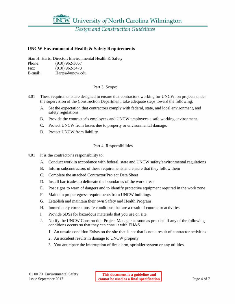
Part 3: Scope:
3.01 These requirements are designed to ensure that contractors working for UNCW, on projects under the supervision of the Construction Department, take adequate steps toward the following: A. Set the expectation that contractors comply with federal, state, and local environment, and
safety regulations. B. Provide the contractor’s employees and UNCW employees a safe working environment. C. Protect UNCW from losses due to property or environmental damage. D. Protect UNCW from liability.
Part 4: Responsibilities
4.01 It is the contractor’s responsibility to: A. Conduct work in accordance with federal, state and UNCW safety/environmental regulations B. Inform subcontractors of these requirements and ensure that they follow them C. Complete the attached Contractor/Project Data Sheet D. Install barricades to delineate the boundaries of the work areas E. Post signs to warn of dangers and to identify protective equipment required in the work zone F. Maintain proper egress requirements from UNCW buildings G. Establish and maintain their own Safety and Health Program H. Immediately correct unsafe conditions that are a result of contractor activities I. Provide SDSs for hazardous materials that you use on site J. Notify the UNCW Construction Project Manager as soon as practical if any of the following
conditions occurs so that they can consult with EH&S 1. An unsafe condition Exists on the site that is not that is not a result of contractor activities 2. An accident results in damage to UNCW property 3. You anticipate the interruption of fire alarm, sprinkler system or any utilities

01 00 70 Environmental Safety This document is a guideline and cannot be used as a final specification
Issue September 2017 Page 5 of 7
K. Notify UNCW EH&S and Construction Project Manager the immediately if the following occur: 1. Unanticipated interruption of fire alarm, sprinkler system or utility interruption 2. Spills or leaks of any hazardous substance that occurs on the worksite 3. An accident occurs that results in death or the injury of three or more persons
4.02 Failure to comply with these requirements can result in termination of the contract. A. It is the UNCW Construction Project Manager’s responsibility to:
1. Ensure the EH&S in invites to all pre-construction meetings 2. Ensure that contractors complete a Contractor/Project Data Sheet 3. Be primary contract with the contractor in environmental, health and safety concerns 4. Call the contractor’s attention to unsafe acts or conditions that they observe 5. Inform EH&S if they have been notified of any conditions that warrant further
investigation to prevent accident occurrences, environmental damage or regulatory fines B. It is the UNCW EH&S Department’s responsibility to:
1. Be present to explain these requirements at pre-construction meetings 2. Provide contractors with emergency information phone numbers 3. Notify the UNCW Construction Project Manager of unsafe acts or conditions observed 4. Notify the contractor if any conditions observed that are immediately dangerous to life,
health or environment 5. Provide the contractor with SDSs for hazardous materials used by UNCW in the area
where they are working.

01 00 70 Environmental Safety This document is a guideline and cannot be used as a final specification
Issue September 2017 Page 6 of 7
6.
UNCW Contractor/Project Data Sheet Contractor Information Company Name: Address: Business Phone Number: Emergency 24-hr Phone: Contractor Project Contact: UNCW Construction Project Manager Project Manager: Phone: Emergency Phone: Project Information Building Where work Conducted: Location of Work: Brief Description of Work to be Performed: Date Work is Expected to Begin: Expected Completion: Expected Work Schedule (Days of week and hours): EH&S Department Information: Fire, Medical and Police: 4911 on campus phone system or (910) 962-4911 from other phones EH&S Phone Number: (910) 962-3057 EH&S Emergency phone 4911 Scope of Work Questionnaire (are the following activities taking place on site)
Activity Yes No Excavation and trenching Asbestos abatement Confined space entry Cranes or hoist Lockout/tagout Fuel storage tanks Generate hazardous waste Modify sprinkler system Use fall protection equipment Use compressed gas cylinders

01 00 70 Environmental Safety This document is a guideline and cannot be used as a final specification
Issue September 2017 Page 7 of 7
Use scaffolding or manlifts Asbestos sampling or Abatement Utilities or life safety systems interrupted

01 00 75 Construction Sign This document is a guideline and cannot be used as a final specification
Issue September 2017 Page 1 of 1
01 00 75 Construction Project Sign
1.01 A construction project sign will be provided by the University using the template below. A. Warning signs may be used as needed. All temporary construction site signage and
other informational signage must be kept to a minimum. B. Contractors must supply signage identifying their company at the entrance and exit of
the construction site.
4’ 0”
3’6”
1’ 1
0”
Project Rendering
PROJECT NAME FONT: Palatino Linotype

01 00 80 Digging and Excavation This document is a guideline and cannot be used as a final specification
Issue September 2017 Page 1 of 2
01 00 80 Digging and Excavation
Part 1: Purpose
1.01 To provide guidelines for digging and excavation operations on university property.
1.02 Scope 1) Applies to all university departments and activities, as well as other persons on university
property. 2) Applies to ALL penetrations of soil on university property accomplished with shovels,
backhoes, trenchers, axes, posthole diggers, tent stakes, or ground rods.
1.03 Policy 1) General Statement:
A. In accordance with North Carolina Occupational Safety and Health (NCOSHA) standards, any individual who has a need to dig or excavate on university property must receive written permission from the UNCW Architectural and Construction Services before commencing digging or excavation operations. The Architectural and Construction Services is responsible for ensuring that all applicable regulations are followed during any digging/ excavation processes performed by Physical Plant employees or by any personnel contracted by the Director of Physical Plant. When other labor is used, the person(s) conducting the digging/excavation operations are responsible for ensuring all applicable regulations are followed.
Part 2: UNCW Digging and Excavation Manual
2.01 Responsibility for Damages 1) Any persons or organizations digging without proper authorization will be responsible for
repair costs to damaged underground utilities.
2.02 Procedures 1) Person(s) desiring to dig on university property must complete and submit a Digging and
Excavating Request form and an area sketch to the UNCW Architectural and Construction Services a minimum of fourteen (14) working days in advance of the proposed digging operations to allow for proper clearance and investigation.
2) The Digging and Excavating Request form can be found at http://www.uncw.edu/physicalplant/forms.html.

01 00 80 Digging and Excavation This document is a guideline and cannot be used as a final specification
Issue September 2017 Page 2 of 2

01 00 90 Supplementary Conditions This document is a guideline and cannot be used as a final specification
Issue September 2017 Page 1 of 8
01 00 90 UNCW Supplementary General Conditions
SUPPLEMENTARY GENERAL CONDITIONS Article 1 –Definitions Paragraph "a": Add the following to the end of the paragraph: "The Geotechnical Technical Report does not constitute part of the Contract Documents, but is included for reference." Paragraph "b": Add the following to the end of the paragraph: “The Owner is defined as The Trustees of University of North Carolina Wilmington. Under the Delegation of Authority granted to University of North Carolina Wilmington by the State Construction Office, throughout the General Conditions, replace "the State Construction Office" or "SCO" with "the Owner". Delete Subparagraph b.in its entirety and substitute the following: "b. The Owner is the State of North Carolina through the University of North Carolina Wilmington." Add the following Subparagraph c. "c. Add “the designers are (insert designer name)”. Add the following Subparagraph h. "h. “The project name is (insert project name).”
Add the following Subparagraph u.
"u. Project Identification: All correspondence, reports, schedules, applications for payment,
fax items, etc. shall contain proper title of project, code, item and SCO ID numbers,
typical," Paragraph "cc": Add the following new paragraph: “Latest edition” shall mean the current printed version of the referenced document issued up to 30 calendar days prior to date of receipt of bids, unless specified otherwise. Paragraph "dd": Add the following new paragraph: “Drawings” or "plans" shall mean the drawings enumerated in the contract documents, as well as all the information in the detail manual (when applicable), addenda, and designer-prepared field drawings and clarification drawings. Paragraph "ee": Add the following new paragraph: “Specifications” mean this project manual and addenda thereto.

01 00 90 Supplementary Conditions This document is a guideline and cannot be used as a final specification
Issue September 2017 Page 2 of 8
ARTICLE 2- INTENT AND EXECUTION OF THE DOCUMENTS Paragraph "a": Add the following new sub-paragraphs:
1. “These drawings and specifications represent the general dimensional and aesthetic requirements for various "in place" materials required to produce {insert project type here} acceptable to the owner for his intended use.
2. It is the intent of these drawings and specifications to provide {insert project type here} and associated appurtenances that are structurally sound and conforming to at least the minimum requirements of the North Carolina State Building Code.
3. The Contractor shall make all reasonable efforts to achieve this intent. If any detail shown on these drawings appears inconsistent with this intent, in the opinion of the Contractor, he shall notify the Designer in writing of his opinion, and await instructions from the Designer before proceeding with the work.
4. Where more detailed information is needed, or when an interpretation of the contract documents is required, the Contractor shall refer the matter in writing to the Designer prior to proceeding with the work. The Designer shall furnish the Contractor an interpretation in writing.
5. If the Contractor discovers errors, inconsistencies, discrepancies or omissions in the contract documents, the Contractor shall inform the Designer of such condition prior to proceeding with the work.
6. If the Contractor discovers errors, inconsistencies, discrepancies or omissions in the contract documents prior to bid, the Contractor shall request clarifications from the Designer and shall include in the bid price all work required to deliver a fully operational and ready to use system.
7. If inconsistencies, discrepancies or contradictions in the Contract Documents are discovered after the bid, the Contractor shall be deemed by submittal of his bid, to have bid the most costly as to labor, materials, duration, sequence and method of construction to provide the work.”
ARTICLE 3 - CLARIFICATION AND DETAIL DRAWINGS Paragraph "a": Add the following to the end of the paragraph: “If errors, inconsistencies or discrepancies in the contract documents are discovered by the Contractor, the Contractor shall inform the designer of such condition prior to proceeding with the work. The designer shall furnish the Contractor written clarification in a reasonable time, so as not to impact the progress of the work. ARTICLE 5 - SHOP DRAWINGS, SUBMITTALS, SAMPLE DATA Paragraph "c": Add the following new paragraph: “This schedule must account for any resubmittals required to obtain approval from the Project Designer and Owner.” Paragraph "d": Add the following new paragraph: “No time extension will be granted for delays caused due to failure of the Contractor to properly review shop drawings prior to submittal to the Project Designer. All shop drawings shall indicate how materials relate to conditions of the project. Standard manufacturer's drawings that do not show how and where material is to be used will not be reviewed by the Project Designer. Shop drawings shall not be reproductions of contract documents. Coordination drawings are required in accordance with Article 14.” Article 8-Materials, Equipment and Employees Delete Article “”e” and replace with the following.

01 00 90 Supplementary Conditions This document is a guideline and cannot be used as a final specification
Issue September 2017 Page 3 of 8
“e” “Each contractor shall obtain written approval from the designer for use of products, materials, equipment and assemblies claimed as equal to those specified. Substitution requests will only be considered up to 10 days prior to the bid date unless the product is no longer manufactured, to comply with governing authorities or as directed by the owner. Reference 01 63 20, Product Substitutions, for additional substitution requirements. Paragraph "e": Add the following to the end of the paragraph: “The Contractor shall obtain written approval from the Project Designer for the use of products, materials, or equipment claimed as equal to those listed in the specifications. Such approvals shall be obtained prior to the opening of the bids. The Contractor shall submit within twenty (20) calendar days following award of contract a complete list of materials to be used for the project for review and approval by the Project Designer. The list shall consist of materials, products and equipment as listed in the specifications, equals, or approved equals. When this list is approved by the Project Designer, no substitution will be permitted except in unusual or extenuating circumstances. If no list is submitted, the Contractor shall supply only materials, products, or equipment required by the specifications.” Add the following to Subparagraph f:
"f. "The designer is the judge of equivalency of materials, products, equipment, assemblies, or installation methods proposed by the Contractor as equivalent to those specified,"
Paragraph "g": Add the following to the end of the paragraph: “All construction personnel shall be respectful to all University of North Carolina Wilmington staff and students. Any disrespect, harassment, unwelcome comments or advances from any construction personnel toward any staff member or student shall constitute sufficient grounds for University of North Carolina Wilmington to request removal of any specific individuals from this project. Such action taken by the Owner shall not constitute grounds for a delay claim. The Owner will not be responsible for any delays caused to the project due to any individual being removed from the project. Project superintendents shall be held accountable for any incident of this nature.”
ARTICLE 10- PERMITS, INSPECTIONS, FEES, REGULATIONS
Paragraph “f”: Add the following paragraph: Notify UNCW EH&S a minimum of one day in advance prior
to performing work requiring a Hot Work Permit.“
ARTICLE 11- PROTECTION OF WORK, PROPERTY, AND THE PUBLIC Paragraph "j": Add the following paragraph: “In case emergency contact is required, the Contractor shall furnish the Owner with names, pager numbers, and telephone numbers (day and night) of the project manager and superintendent. The numbers shall remain current for the duration of the project, and shall be updated as required.” Paragraph "k": Add the following paragraph: “The Owner will provide security as it deems prudent and necessary for its own protection. The Contractor shall be responsible for security and safety of the project within the project limits, including on-site materials. The Contractor and the Owner shall meet on a regular basis as required but not less than weekly to coordinate safety and security issues.”

01 00 90 Supplementary Conditions This document is a guideline and cannot be used as a final specification
Issue September 2017 Page 4 of 8
Paragraph "l" Add the following paragraph: “The Owner will conduct normal operations during the duration of the project. Unless otherwise stated, the campus buildings will be occupied and will operate on a normal schedule. This means that the Contractor will be required to schedule work around regular operations, special events, visitors and staff requirements. The Contractor shall coordinate with the Owner's representative to minimize any disruptions to the functions of the College.”
ARTICLE 12- SEDIMENTATION POLLUTION CONTROL ACT OF I973 Paragraph "e": Add the following new paragraph: “The Contractor shall comply with the following requirements: Equipment utilized during the construction activity on a site must be operated and maintained in a manner as to prevent the potential or actual pollution of the surface or ground waters. Fuels, lubricants, coolants, and hydraulic fluids, or any other petroleum products, shall not be discharged on the ground or into surface waters. Spent fluids shall be disposed of in a manner so as not to enter the waters, surface or ground, and in accordance with applicable state and federal disposal regulations. Any spilled fluids shall be cleaned up to the extent practicable and disposed of in a manner so as not to allow their entry into the waters, surface or ground, storm sewers, or drains on private or public property. Herbicide, pesticide, and fertilizer usage during the construction activity shall be restricted to those Materials approved by EPA and shall be used in accordance with label instructions. All wastes composed of construction materials shall be disposed of in accordance with NC General Statutes, Chapter 130A, Article 9- Solid Waste Management, and rules governing the disposal of solid waste (NC Administrative Code Section l5A NCAC 13B).” Paragraph "f": Add the following new paragraph: “Minimum Monitoring and Reporting Requirements 1. All sedimentation and erosion control of facilities shall be inspected by the Contractor at least once every seven calendar days and within 24 hours after any storm event of greater than 0.5 inches of rain per 24 hour period. 2. Storm water runoff discharges shall be inspected by visual observation for color, foam, outfall, staining, visible sheens, dry weather flows and muddy water (at the frequency described above) to evaluate the effectiveness of the pollution control facilities or practices. If any visible off-site sedimentation is leaving the site, corrective action shall be taken to reduce the discharge of sediments. 3. The Contractor shall submit to the Owner a written report of weekly inspections. Visible sedimentation found off the site shall be recorded with a brief explanation as to the measures taken to prevent future releases as well as any measures taken to clean up the sediment that has left the site. This record shall be made available to Department of Environmental Management or authorized agent upon request. Paragraph "g": Add the following new paragraph: “Maintenance and Inspections
1. The Contractor shall keep all erosion controls devices and materials in good repair. The Owner reserves the right, within 24 hours prior notice to the Contractor to repair any erosion control measures or materials as required, and deduct the cost of those repairs from the Contractor’s application for payment.
2. The owner's representative may periodically evaluate the project for compliance with these requirements.”

01 00 90 Supplementary Conditions This document is a guideline and cannot be used as a final specification
Issue September 2017 Page 5 of 8
Article 14-Construction Supervision and Schedule.
Revise Subparagraph e to read as follows:
"e. "The contractor shall employ an engineer or a land surveyor licensed in the State of North Carolina to lay out the work. The engineer or land surveyor shall establish a benchmark nearby in a location where same will not be disturbed and where direct instrument sights may be taken. In such case, the engineer or land surveyor shall coordinate the project benchmark with known campus benchmarks."
ARTICLE 15 – SEPARATE CONTRACTS AND CONTRACTOR RELATIONSHIPS Paragraph "g": Add the following new paragraph: E-Verify Compliance: Pursuant to Session Law 2013- 418, Contractor shall fully comply with the U.S. Department of Homeland Security employee legal status EVerify requirements for itself and all its subcontractors. Owner requires an affidavit attesting to Contractor’s compliance. Violation of the provision, unless timely cured, shall constitute a breach of contract. Article 23 -Time of Completion. Delays. Extension. Add the following:
"h. Time.
1. The Contractor shall commence work to be performed under this agreement on a date to be specified in a written order form the designer and shall fully complete all work within {insert time here} consecutive calendar days from, and including said date. For each day in excess of the above number of days, the Contractor shall pay to the Owner the sum of {insert LD amount here} as liquidated damages reasonably estimated in advance to cover the losses to be incurred by the Owner by reason of failure of said Contractor to complete the work within the time specified, such time being in the essence of this contract and a material consideration thereof."
Paragraph "i": Add the following new paragraph: “Working hours: The Contractor shall establish a working hour and date schedule and submit to the Owner’s representative for approval. Any deviations from this schedule shall be requested from and approved by the Owner at least five (5) work days in advance.
1. The Contractor shall agree to additional restrictions on working hours and days as may be enforced by the Owner during certain periods of the year such as, but not limited to, the week of final exams and move in for each semester.
2. Working hours {insert working hours} Article 31 Request for Payment. Add the following:
"c. The Contractor shall submit a schedule of values within 14 days from date of Construction Contract. The Schedule of Values shall have separate line items for each
01 00 90 Supplementary Conditions This document is a guideline and cannot be used as a final specification
Issue September 2017 Page 6 of 8
specification section. Additionally, each section shall have individual lines for material and labor."
“f. Contractor shall submit to the Designer a request for payment on AIA Document G702
unless otherwise approved by the Designer”
Article 34 -Minimum Insurance Requirements Revise minimum limits and coverage Subparagraph b:
"Bodily Injury {insert amount here} per occurrence Property Damage: {insert amount here}per occurrence/{insert amount here}
aggregate, And shall include explosion, utilities, and collapse (X,U,C) coverage.
{insert amount here}: Combined Single Limit to satisfy both Bodily Injury and Property Damage.
Revise Subparagraph c as follows: Add the following sentence: "Property insurance specified in Subparagraph c shall include the
Owner, the Architect and his consultants, the Contractor and his subcontractors as additional insured parties in the policy." In the second sentence after the words "against the perils of fire," add the following: "hurricane, flood and wind."
ARTICLE 38 – USE OF PREMISES Paragraph "e": Add the following new paragraph: “Storage of construction materials shall be limited to the staging area, as defined in the contract documents.” Paragraph "f": Add the following new paragraph: “Where equipment must cross walks, landscaping areas, or ramps, the Contractor shall provide ¾” plywood sheets for protection of these areas. Cross walks, landscaping areas, or ramps damaged by construction activity shall be repaired or replaced.” Paragraph "g": Add the following new paragraph: “The construction site and staging areas as well as Owner’s adjacent campus areas shall be kept free of trash, litter, and debris at all times.” Paragraph "h": Add the following new paragraph: “Grass in the construction site shall be mowed as often as required to maintain a neat appearance. Tree protection shall extend at least to the drip line of the trees to be protected. Unless otherwise shown on the drawings, minimum tree protection shall include four foot landscaping fencing supported with steel stakes four foot on center. Al l areas under the drip line of trees are off limits to vehicular traffic unless protected by plywood.” Paragraph "i": Add the following new paragraph: “Landscape protection when required, shall be installed prior to the initial grading stage. No storage of any kind, access, or activity of any kind will be permitted inside the landscaping protection areas.” Paragraph "k": Add the following new paragraph: “When required by the drawings, a construction fence

01 00 90 Supplementary Conditions This document is a guideline and cannot be used as a final specification
Issue September 2017 Page 7 of 8
shall be installed. The fence shall be construction of heavy-duty chain link material, have a minimum height of six feet and it shall have a continuous top tubular rail. Swing gates shall be included at all and every access to the enclosed area.” ARTICLE 39 - CUTTING AND PATCHING Paragraph "a": Add to the end of Paragraph: “The Contractor shall be responsible for locating underground utilities prior to excavation. The construction manager may obtain the services of a commercial utilities locator and/or various utility companies who may have lines inside the area. In addition, Contractors shall contact the Owner's Representative at least five days prior to excavation. The Contractor will be responsible for utility interruptions caused by construction operations including excavations.” Paragraph "d": Add the following new paragraph: “All cutting and patching required to perform the work, and to install the specified products under a particular contract shall be performed under that particular contract. All patching work shall be made by craftsmen skilled in the required work on who may already be engaged on the project. All painting within previously painted areas shall be painted by the contract which caused the need for this painting, unless new finishes have been scheduled. All painting shall be by skilled painters who may already be engaged on the project.” Article 40 -Utilities. Structures. Signs.
Revise Subparagraph “a” to read as follows:
"The contractor shall provide necessary and adequate facilities for water, electricity, gas, oil sewer, and other utility services which may be necessary and required for completion of the project. The University owns the water, sewer, gas, telephone and electrical utilities on campus. The contractor shall arrange for and provide all appurtenances necessary for the provision of temporary services, including connections to existing utilities. Temporary telephone service shall be obtained and paid for by the contractor through the University's telecommunications department. Connections for all other utilities shall be performed under the supervision of Physical Plant personnel. In all cases, the contractor shall give a minimum of 72 hours notice for the connection of all utilities.
The Contractor shall provide temporary electric, gas and water meters on University-owned utility services to the building. The University will read the meters on a monthly basis, and will pay for the cost of consumption for these utilities. The University reserves the right to back charge the contractor if the University finds negligence in the use of utilities.
Charges for telephone and data utilities will be charged to the contractor directly by UNCW
Telecommunications Department on a monthly basis. Contractor is advised to confirm current telephone and data rates with UNCW Telecommunications Department (910) 962-4019.
Add the following to item j.:
"General Contractor shall provide his own office facility including telephone and facsimile machines required at location on site approved by the Architect and Owner. The Office shall be weather-tight with lighting, electrical outlets, heating, cooling equipment and equipped with sturdy furniture, drawing rack and drawing display table. The office shall also include a desk and telephone/data outlet. General Contractor's office shall be large enough for his own use and for use as a

01 00 90 Supplementary Conditions This document is a guideline and cannot be used as a final specification
Issue September 2017 Page 8 of 8
coordination office to include meeting space with table and chairs for 16 people. Portable toilets must be provided on site. The Owner's toilet facilities shall not be used at anytime during the project."
Paragraph “m": Add the following new paragraph: “It is imperative that Owner’s utilities and other services be maintained at all times except for scheduled interruptions. Any necessary utility interruptions shall be approved by the Owner's Representative at least three weeks in advance. If necessary, work shall be performed at night, over the weekend, or during holidays. No extra payment will be made for such work. When utility services cannot be interrupted for the length of time required, the Contractor shall make provisions for temporary services. Pedestrian traffic around the construction limits must be maintained in a clean and safe condition at all times.”
Article 42 – Guarantee Add the following: “e. All warranty periods to be begin at “Final Acceptance” date rather than at the “Substantial Completion“ date.”
Article 45 – Taxes Add the following:
"e. Contractors shall submit monthly with their request for payment, a signed statement containing the amount of sales and use tax paid by the Contractor for that particular billing period on the documents included in the project specifications.”
Article 48 – Asbestos-Containing Materials (ACM) Add the following:
"{Confirm if this is applicable}No asbestos containing material may be used in this facility, including but not limited to, sprayed-on insulation, pipe insulation, floor tile, mastic adhesive, patch materials, wiring insulation, or acoustical treatment."
END OF UNCW SUPPLEMENTARY GENERAL CONDITIONS

01 10 10 CAD Standards This document is a guideline and cannot be used as a final specification
Issue September 2017 Page 1 of 2
01 10 10 CAD Standards
Part 1: Overview:
1.01 These Guidelines are issued to promote the development of AutoCAD drawings suitable for use in the University of North Carolina Wilmington’s Office of Facilities CAD environment. Electronic drawings produced and submitted in accordance with these guidelines have significantly greater value to the institution, helping to provide consistency and compatibility with existing AutoCAD documents. Architects, Engineers, Design Professionals and Contractors delivering AutoCAD documentation to UNCW must ensure these guidelines are reviewed and understood by those persons responsible for preparing AutoCAD drawings. All AutoCAD drawings forwarded to UNCW shall be submitted in a timely fashion, coinciding with the needs of the project and UNCW staff. The delivery of AutoCAD documentation during various project stages shall be timed appropriately to ensure that UNCW ultimately receives the most accurate information available. The receipt of electronic AutoCAD drawings alone does not alleviate the responsibility of the Architect, Engineer or Consultant of providing original signed and sealed hard copy documentation to UNCW. Other UNCW contracts or construction documents may reference this document.
Part 2: Drawings
2.01 Formats: A. UNCW requires that all project drawings be created and submitted using AutoCAD (.dwg file
extension) software. AutoCAD version 2008 or newer up to version 2015 is required.
2.02 Drawing Content: A. Prior to submitting drawings to UNCW, AutoCAD files containing multiple drawing sheets
shall be broken down into separate drawings containing single sheets. Multiple layout tabs are not to be used.
B. The drawing file name shall match the drawing number on the title bar. C. The proper layer state shall be restored for each drawing submitted. D. All CAD drawings shall be purged of empty, unused, or non-essential drawing data. E. All externally referenced data (XREF’s) that were used in the Cad drawings shall be inserted
and bound, using the “bind” command. 1. Bound XREF’s shall have their layers intact.
F. No CAD drawings that contain xref’s will be accepted. G. Each final submitted drawing sheet shall have “As-Built” or “Record Drawing” clearly
marked on every electronic and printed sheet. H. Text styles and fonts may vary, however, custom fonts and hatch styles not packaged within
AutoCAD are not permitted. I. All blocks must be created on layer “0”. Nested blocks should be avoided.

01 10 10 CAD Standards This document is a guideline and cannot be used as a final specification
Issue September 2017 Page 2 of 2
J. All objects, layers and line types must be defined as “BYLAYER”.
2.03 Model and Paper Space Usage: A. The primary drawing(s) shall be created in model space. B. All drawings created within model space must be drawn to full size (1:1 scale). C. Any additional items such as details, dimensions, elevations, or sections should be drawn to
full scale in model space. D. General project graphic elements such as title blocks should be drawn in paper space.
Elements such as legends, schematics, key plans, diagrams and notes may also be drawn in paper space.
E. Scale objects using paper space viewports – zoom viewports to the appropriate scale. F. Label scale of each viewport in paper space. G. Viewports should be created on a “viewport” layer.
Part 3: Drawing Submittal Requirements:
3.01 General: A. Include a transmittal sheet with submittals indicating UNCW project number, UNCW project
name and a complete list of all materials submitted. B. Deliver one set of original signed and sealed hard copy prints along with the electronic
drawing submission. All electronic drawings shall be submitted on a CD/DVD, USB Drive or transmitted electronically. These drawings should be labeled with project name, type of drawing package (i.e. bid set, construction drawings, record drawings), and date created.
C. All content of the electronic drawings must match the delivered hard copy version. The electronic file should look exactly like the hard copy version when the file is opened by UNCW personnel.
3.02 As-Built Submittal Requirements: A. On completion of the project the Designer is responsible for providing a signed and sealed
complete set of drawings to UNCW. Mark all drawings with ‘As-Built’ (for completed and final submittals of a new building or new building addition drawing set) or ‘Record Drawings’ (for final submittal of drawings of remodeling projects, shop drawings and site works) and subscribe to the previously recommended CAD standards.
B. Designers are responsible for incorporating any changes in the field submitted by the Contractors into the final drawings. Scans of the Contractor’s hard copy as-built drawings will not be accepted.

01 10 15 Specifications Standards This document is a guideline and cannot be used as a final specification
Issue September 2017 Page 1 of 1
01 10 15 Specification Standards
Part 1: General
1.01 Specification Format: A. Specifications shall be organized based on the latest “MasterFormat” version.
1.02 Specification Content: A. The Designer shall:
1. Make every effort to ensure that the specifications are as clear and un-ambiguous as possible.
2. Review specifications to be thoroughly coordinated. 3. Conduct a thorough in-house review, of all disciplines, to eliminate conflicting
requirements. 4. Verify that the responsibilities that must be fulfilled by the Contractor or by others is
clearly delineated and that it encompasses all work required to provide a finished and useable product. There should be no ambiguous terminations where one trade or Contractor stops and another begins.
1.03 Product Choices: A. A minimum of three manufacturers must be provided for each product specified. B. When specifying a product, always provide the actual manufacturer name. The local
representative or distributor contact information may be provided as additional information. C. Verify that materials specified are current and available. D. Verify model numbers provided are current. E. Identify if a chosen product option is standard or custom.

04 00 00 Masonry This document is a guideline and cannot be used as a final specification
Issue September 2017 Page 1 of 7
04 00 00 Masonry General Requirements
Part 1: Brick Veneers
1.01 Face Brick: Basis of Design: Statesville Brick Company “Red Royal Special”
1.02 Mortar And Grout Materials A. Mortar color shall be light grey. Basis of Design is masonry cement by Giant in standard
grey color to match existing mortar on campus. B. Mortar joint shall match existing on campus.
1.03 Expansion Joints A. If possible, locate the expansion joints behind the downspouts.
1. See Section 07 92 00 Joint Sealants
1.04 Cold Weather Provisions A. Specify cold weather construction provisions when construction schedule indicates cold
seasonal conditions will be likely.
Part 2: Embedded Flashing Materials
2.01 Hidden from view: Copper-Laminated Flashing: 5-oz./sq. ft. copper sheet bonded with asphalt between 2 layers of glass-fiber cloth. Use only where flashing is fully concealed in masonry.
2.02 Exposed to view: Through-wall flashing that projects out from face of wall shall be 16 oz. copper.
Part 3: Miscellaneous Masonry Accessories
3.01 Weep-Prefab: A. Basis of Design: Wire-Bond #3601 “Cell Vent”
1. Size: 3/8” wide x 2-1/2” high x 3-3/8” long 2. Color: Clear 3. Material: Polypropylene copolymer
3.02 Cavity Drainage Material: Free-draining mesh, made from polymer strands that will not degrade within the wall cavity. Strips, full-depth of cavity and 10 inches wide, with dovetail shaped notches 7 inches deep that prevent mesh from being clogged with mortar droppings.
Part 4: Brick Screen Walls

04 00 00 Masonry This document is a guideline and cannot be used as a final specification
Issue September 2017 Page 2 of 7
4.01 Pierced brick walls and brick columns. Columns to have precast caps. Height as necessary to hide items being enclosed. Wall width to be 12” and columns to be 24”x24”.

04 00 00 Masonry This document is a guideline and cannot be used as a final specification
Issue September 2017 Page 3 of 7
Part 5: Drawings
5.01 Indicate on the drawings the following information related to Unit Masonry: A. Extent of each type of engineered and empirically designed masonry and delineate, as
required, to show dimensions (nominal thickness, cavity width, setting bed thickness, etc.) and construction (single wythe, multi wythe, composite, cavity, etc.).
B. Details of anchors, ties, reinforcing, joint reinforcement, lintels, chases, and recesses or openings for other construction.
C. Colored mortar, if any. Indicated as either “Colored Aggregated Mortar” or “Pigmented Cement Mortar.”
D. Pattern bonds for exposed surfaces, if other than running bond. E. Structural bonding between wythes (continuous wire reinforcing) and spacing of same. F. Extent of insulation for cavity walls and in hollow units. G. Location of movement joints and details of each type of movement joint. Show isolation
joints between masonry and concrete, and masonry and steel framing, if any. H. Location, types, and details of items to be built into masonry such as anchors, ties, inserts,
lintels, flashing, reglets and insulation nailers. I. Details of special bearing areas (particularly for hollow unit masonry) showing extent and
type of high-strength units, such as solid CMU areas in hollow CMU walls, grout or concrete fill for hollow CMU, bond beams, and other special construction required for structural bearing.
J. Details of masonry lintels if construction exceeds nominal construction specified. K. Details of special masonry features for walls, such as chases and recesses and openings for
other work. L. Fire resistance ratings (4 hour, 3 hour, etc.) if any.
Part 6: Reference Design Standards
6.01 Typical Masonry Details A. Jack Arch B. Brick Quoins C. Masonry openings for Windows D. Cast stone sill
6.02 See also UNCW Original Campus Construction Documents.
Part 7: Reference drawings and photos:
7.01 See next pages for related details taken from Original Campus Construction drawings.

04 00 00 Masonry This document is a guideline and cannot be used as a final specification
Issue September 2017 Page 4 of 7
TYPICAL JACK ARCH Reference: Alderman Hall, Sheet #12

04 00 00 Masonry This document is a guideline and cannot be used as a final specification
Issue September 2017 Page 5 of 7
TYPICAL BRICK QUIONS Reference: Alderman Hall, Sheet #21

04 00 00 Masonry This document is a guideline and cannot be used as a final specification
Issue September 2017 Page 6 of 7
REFERENCE PROFILE for CAST STONE SILLS Reference: Alderman Hall, Sheet #14

04 00 00 Masonry This document is a guideline and cannot be used as a final specification
Issue September 2017 Page 7 of 7
TYPICAL BRICK SCREEN WALL – PIERCED PATTERN

05 73 00 Decorative Metal Railings This document is a guideline and cannot be used as a final specification
Issue September 2017 Page 1 of 2
05 73 00 Decorative Metal Railings
Part 1: Decorative Railing for Exterior and Interior Use
1.01 Reference drawings from Alderman Hall.
TYPICAL RAILING Reference: Alderman Hall
Sheet #15

05 73 00 Decorative Metal Railings This document is a guideline and cannot be used as a final specification
Issue September 2017 Page 2 of 2
1.02 Reference drawing from a recent project fabricated using aluminum.

05 50 00 Metal Fabrications This document is a guideline and cannot be used as a final specification
Issue September 2017 Page 1 of 1
05 50 00 Metal Fabrications
Part 1: Loose Steel Lintels
1.01 Exterior wall steel lintels to be galvanized, primed, and painted. A. Use zinc-rich primer when exposed to wet environments.
Part 2: Metal Ladders
2.01 Exterior ladders to be hot dip galvanized after fabrication.
2.02 Prime exterior ladders and interior ladders including brackets and fasteners when item is to be painted.

06 64 00 Plastic Panels This document is a guideline and cannot be used as a final specification
Issue September 2017 Page 1 of 1
06 64 00 Plastic Panels
Part 1: Applications
1.01 Kitchen Walls A. Material: Fiberglass Reinforced Plastic (FRP) B. Sheet size: 4 foot width by longest practical length to minimize seams. C. Thickness: Varies D. Finish: As specified by Designer E. Color: As specified by Designer F. Installation: Adhesive G. Accessories: Manufacturer’s standard trim accessories. H. Rating: Provide fire rated products when required.
Part 2: Materials
2.01 Products A. Basis of Design Product: “Glasbord” series by Crane Composites.

06 00 00 Wood & Carpentry This document is a guideline and cannot be used as a final specification
Issue September 2017 Page 1 of 3
06 00 00 Wood and Carpentry General Requirements
Part 1: Drawings and Detailing
1.01 Rough Carpentry: A. General: NO WOOD SHALL BE USED ON THE EXTERIOR.
1. An exception to this would be sheathing as part of an insulated roof nailable base assembly for installation of shingles. This wood is required to be fire-treated and pressure treated.
2. The Designer must obtain prior approval from the University Property Manager for the use of wood in other exterior locations.
B. Indicate on drawings the following information related to Rough Carpentry. 1. Extent, size, and spacing of rough carpentry, such as grounds, stripping, blocking and
equipment base “skids”. Use nominal sizes for dimension lumber, actual sizes for engineered (worked) wood elements.
2. Actual thickness for panel products, including construction panels, particleboard, hardboard underlayment, gypsum sheathing, fiberboard sheathing, and other panel products.
3. Details of typical and special conditions; clearly differentiate between “carpentry” (rough and finish) and “architectural woodwork”.
4. The extent of preservative-pressure-treated and fire –retardant-treated wood.
1.02 Exterior Architectural Woodwork: A. General: NO EXTERIOR WOODWORK PERMITTED.
1. Trim and Ornamentation shall be Exterior GFRC. (see 09 29 50 Polymer Modified GFRC) B. Indicate on drawings the following information related to Exterior GFRC:
1. The extent of each assembly of GFRC. 2. Clearly distinguish responsibility of backup provider and other supporting construction
specified elsewhere. 3. Dimensions for principal elements of exterior woodwork, and profiles of jambs, trim,
siding and molding (including special joinery).
1.03 Custom Built-In and Furniture: A. Custom Built-in vs. Freestanding and/or Readymade Furniture:
1. Ready-made furniture is preferred. 2. The use of freestanding furniture is preferred. This choice provides easy and low-cost
space allocation changes and relocations. 3. Custom and built-in furniture should be avoided where possible.

06 00 00 Wood & Carpentry This document is a guideline and cannot be used as a final specification
Issue September 2017 Page 2 of 3
1.04 Interior Architectural Woodwork: A. Indicate on drawings the following information related to Interior Architectural Woodwork:
1. The extent of each type of interior woodwork, clearly distinguished from carpentry and other wood construction specified elsewhere.
2. Dimensions for principal elements of the work and profiles of jambs, trim and moldings (including special joinery).
3. Location of quality grades, if more than one specified for each category and finish, and the location of each cannot be adequately specified.
4. Special veneer matching areas where too difficult to be specified in specification. 5. Wood grain direction and plastic laminate pattern direction (where not obvious from the
specification or detailing). 6. Where fire-retardant treated woodwork is required to be installed. 7. Hardware Applications (coordinated with specification and/or scheduling method used)
for cabinet hardware, as distinguished from door hardware. 8. Arrangement of door hardware locks, light fixtures, panel hangers, concrete inserts
(anchorage), and similar hardware and accessories not fully covered by specification. 9. Glass doors, shelves and other similar non-wood elements of the work of this section.
Part 2: Architectural Woodwork Standards and Characteristics
2.01 Applicability: A. With the exception of hardware and glass, construction included in this section is specified to
comply with Architectural Woodwork Institute (AWI) standards. B. Grade of Woodwork: Woodworking standards have been developed on the basis of
designated quality by three separate grades – Premium, Custom and Economy. 1. Premium requires the highest grade of materials and workmanship currently recognized.
It is intended for the finest work and is the most expensive grade. Premium grade might be specified for woodwork throughout an entire building, but it should not be specified indiscriminately. Premium should usually be specified only for selected areas or selected items that have particular architectural significance.
2. Custom is the middle or normal grade in both material and workmanship requirements and is intended for medium-quality regular work.
3. The economy is the lowest acceptable grade in both material and workmanship requirements and is intended for work where price outweighs quality considerations.
a. UNCW does not recommend the use of Economy grade woodwork for the campus. C. Substantial cost differences exist between the different grades, finishes and, for casework,
different types of cabinet construction. Transparent finished woodwork is also generally much more expensive than woodwork with an opaque finish, depending not only the species and cut of wood selected but also on the kind of finish required.
D. Determination of quality grade should be based on a careful study of design role, function, location and finish of each woodwork item. If more than one grade is specified on the same job, drawings or specifications must indicate locations and extent of each grade.

06 00 00 Wood & Carpentry This document is a guideline and cannot be used as a final specification
Issue September 2017 Page 3 of 3
2.02 Fire Retardant Treatment: A. Usually small amounts of architectural woodwork are permitted for most occupancies and
spaces without requiring fire-retardant treatment. However, for many applications where woodwork (of any type) is extensive, such treatment of all or part may be required or advisable. However, use of fire-retardant wood limits choices available with respect to material and thickness and well as to treatment and finishes, particularly transparent finishes.
2.03 Cabinet Hardware: A. Because of the quality of work involved in this section, it is generally advisable to specify
that the cabinet hardware be furnished and installed by the cabinet fabricator so that a single responsibility is achieved. This minimizes problems with coordination and delivery as well as the possibility of potential damage to the finish materials if hardware is supplied and installed in the field by others. Pivot hinges, however, should be supplied and installed in the field because of their tendency to shift during setting and fitting of cabinets.
2.04 Chair Rails: A. Chair rails shall be considered in the design of rooms which are to contain moveable
furniture. Chair rails should be a material that does not require frequent painting.

07 00 00 Thermal and Moisture This document is a guideline and cannot be used as a final specification
Issue September 2017 Page 1 of 2
07 00 00 Thermal and Moisture Protection General Requirements
Part 1: General Requirements:
1.01 Where possible the use of “flat” roofs is to be avoided, but in no case will any portion of a roof have a slope less than ¼ inch per foot.
1.02 The use of skylights is prohibited.
1.03 Installations of solar energy panels on roofs are prohibited. (i.e. Photovoltaic, hot water, etc.)
1.04 The preferred style of shingle is “architectural.” (see section 07 31 00 Moderate Slope Roofing)
1.05 All toilet areas, shower areas, wash rooms, custodial closets/storage rooms, mechanical equipment rooms, water closets, and any other area exposed (or with the potential to be exposed) to water or water overflow shall be sealed in a manner approved by UNCW Physical Plant. The Designer shall incorporate this requirement into the Contract Documents.
Part 2: Gutters and Downspouts
2.01 All gutters and downspouts are to be constructed of copper. A. See section 07 62 00 Sheet Metal Flashing and Trim
Part 3: Roofs
3.01 Fall Protection: A. All roofs shall have permanent fall protection. (See section 07 53 80)
3.02 Low Slope Roofing Systems: A. Membrane Roofing Systems: (See section 07 50 00 Low Slope Roofing) B. Walkway systems shall be installed to and around all mechanical equipment. C. Indicate on the drawings the following information as required:
1. Roof plan for each area of roofing, clearly indicating the extent of each type roofing, including slopes, and including insulation and vapor retarders (if any).
2. Type of Insulation. 3. Required thickness and taper of insulation. 4. Taping of substrate or insulation joints, where required. 5. Flashing, stripping, sealants, cants, tapered edge strips, nailers, reglets, etc. at the
termination of roofing. Show nailers where required. 6. Details of roof drains and other waterways and drainage facilities.

07 00 00 Thermal and Moisture This document is a guideline and cannot be used as a final specification
Issue September 2017 Page 2 of 2
7. Locations and dimensions of walkways (if any), and how they are supported against slippage if the slope is more than 2 inches per ft.
8. Color of surfacing, if other than color specified. 9. Areas of special UL rating, if any (other than rating specified). 10. Locations and large-scale details for sheet metal roofing accessories, and type metal if
several specified. 11. Locations and large-scale details of roof expansion joints, curbs, penetrations, equipment
supports, etc. (Use NCRA details as a guide).
3.03 Moderate Roofing Systems: A. Shingles: (See section 07 31 00 Moderate Slope Roofing) B. Indicate on the drawings the following information as required:
1. Roof plan for each area of roofing, clearly indicating the extent of each type roofing, including slopes, and including insulation and vapor retarders (if any).
2. Type and thickness of insulation. 3. Taping of substrate or insulation joints, where required. 4. Flashing, stripping, sealants, reglets, etc. at the termination of roofing. 5. Details of roof drains and other waterways and drainage facilities. 6. Color of surfacing, if other than color specified. 7. Areas of special UL rating, if any (other than rating specified). 8. Locations and large-scale details for sheet metal roofing accessories, and type metal if
several specified, roof expansion joints, curbs, penetrations, equipment supports, etc.

07 31 00 Moderate Slope Roofing This document is a guideline and cannot be used as a final specification
Issue September 2017 Page 1 of 1
07 31 00 Moderate Slope Roofing
Part 1: General
1.01 The UNCW Standard is asphalt shingle roofing for moderate slope roofs.
Part 2: Materials
2.01 The basis of Design Product: “Timberline Ultra” by GAF Materials Corporation.
2.02 .040 peel and stick membrane are required at ridge, valley and eave conditions.
2.03 Provide minimum 30# felt underlayment.
2.04 The installer shall provide a minimum six nail per shingle or as recommended by the manufacturer for high wind conditions.
2.05 All asphalt shingle installations shall be ventilated.
2.06 Ridge vents shall be rated against water infiltration to wind speeds of 130 mph.
Part 3: Warranty
3.01 Manufacturer’s warranty: 30-years prorated, 20-years non-prorated. 1) Also 15-year wind damage and 10-year algae-discoloration warranties.
3.02 Installer’s 10-year workmanship warranty is required.

07 50 00 Low Slope Roofing This document is a guideline and cannot be used as a final specification
Issue September 2017 Page 1 of 1
07 50 00 Low Slope Roofing
Part 1: General
1.01 Low Sloped Roofing is not permitted on the campus of UNCW without the written approval of the assigned UNCW project manager.
Part 2: Materials
2.01 Low slope roofing shall be .060 non-reinforced EPDM with a white face color.
2.02 A ¼” glass matt recovery board is required.
2.03 Insulation board shall be a polyisocyanurate with a minimum aged insulating R-value as established by the prescriptive requirements of the North Carolina Building Code. Insulation board shall be mechanically fastened.
2.04 Membrane shall be fully adhered.
2.05 Roofing shall meet a minimum roof slope of ¼” per foot.
2.06 Non-organic walk pads are required if the equipment is placed on the roof.
2.07 Roofing shall be specified to meet or exceed the current version of ASCE 7.
Part 3: Shop drawing requirements must include.
3.01 Sealed engineering documents demonstrating compliance with ASCE-7
3.02 Fastening schedule with cut sheets of fasteners.
3.03 Roof slopes, depth of insulation and roof drain locations.
Part 4: Warranty
4.01 Manufacturer’s twenty-year warranty is required.
4.02 Installer’s two-year warranty is required.

07 53 80 Fall Protection This document is a guideline and cannot be used as a final specification
Issue September 2017 Page 1 of 1
07 53 80 Fall Protection
Part 1: General
1.01 Permanent fall prevention/protection measures must be included as an integral part of the design phase for all new construction projects and roof renovation/repair projects at UNCW. All walking/working surfaces where employees are exposed to fall hazards (i.e. roof systems and floor openings) shall be permanently guarded or have qualified anchorages for personal fall arrest systems. Buildings that utilize powered platforms for exterior maintenance shall be provided with qualified anchorages and tie-in guides as necessary.
1.02 A qualified person with extensive experience in fall protection is required to plan, evaluate, design, and select the most appropriate fall prevention/protection solution. Building anchorages, tie-downs, and any other affected parts of the building shall be designed and certified by a registered Professional Engineer (PE) currently registered in North Carolina with expertise in fall protection systems.
1.03 A complete understanding of the work procedures will enable the design team and/or qualified person to select the most appropriate fall protection system. The schematic design phase shall include consultation with affected campus maintenance personnel that are exposed to fall hazards. The purpose of this meeting will help identify specific building maintenance and/or equipment service activities required to be conducted throughout the life of the building. In addition, the design team can discuss maintenance and inspection requirements of the proposed personal fall arrest systems and identify areas of concern.
Part 2: Materials
2.01 Basis of Design: Specified components are manufactured by Guardian Fall Protection Inc., 26513 79th Ave. S, Kent WA 98032, and are specified as the established standard of quality.
Part 3: Quality Assurance
3.01 Qualifications of the Manufacturer: Fall protection components used in the work of this section shall be produced by manufacturers regularly engaged in the manufacture and design of similar items and with a minimum of ten (10) years documented experience of successful design and production acceptable to the Owner.
Part 4: Warranty
4.01 Qualifications of the Installer: The fall protection system installer shall have a minimum of five (5) years documented experience in the installation of rooftop fall protection systems and a minimum of five (5) documented projects of similar type.

07 92 00 Joint Sealants This document is a guideline and cannot be used as a final specification
Issue September 2017 Page 1 of 1
07 92 00 Joint Sealants
Part 1: Applications
1.01 Brick Veneer Expansion Joints A. Basis-of-Design Product: Tremco Dymeric 240FC B. Color:
1. Basis-of-Design: Tremco “Baptist Brick” C. Location of expansion joints:
1. If possible, locate the expansion joint behind the downspouts.

07 62 00 Sheet Metal Flashing & Trim This document is a guideline and cannot be used as a final specification
Issue September 2017 Page 1 of 1
07 62 00 Sheet Metal Flashing and Trim
Part 1: General
1.01 Exposed to View roof edge and roof drainage components: Gutters, Downspouts, Scuppers, Metal counter flashings, Splash pans shall be copper. A. 16 oz. Copper Sheet ASTM B 370, cold-rolled copper sheet, H00 or H01 temper. B. Fabricate in minimum 96-inch- long sections.
1.02 Downspouts to be fabricated with rectangular downspouts complete with mitered elbows.

08 00 00 Doors General Guidelines This document is a guideline and cannot be used as a final specification
Issue September 2017 Page 1 of 2
08 00 00 Doors - General Guidelines
Part 1: General
1.01 Keying Conference: A Keying Conference shall be conducted five to six months prior to completion of each Building Project. As a minimum the General Contractor, UNCW Construction Services Project Manager, Department Heads, UNCW Locksmith and Keying Representative (Schlage) shall be present.
1.02 All doors shall be solid core. Where appropriate doors shall be provided with view panels/lights, especially in high traffic areas.
1.03 All exterior doors shall be FRP 6 panel with continuous hinges. A. Aluminum may also be used. B. Hollow metal doors may be used for exterior utility room doors where not in direct view to
the public areas.
1.04 All hallway and stairwell doors shall have vision panels and continuous hinges.
1.05 Knock-Down frames are not permitted except where specifically noted or where absolutely required in renovation work.
Part 2: Drawings
2.01 All doors. Indicate on drawings the following information: A. Location of each door and frame unit. B. Direction of door swing (hand). C. Size and type of units, by elevation. Indicate if door thickness other than 1 ¾ inches. Show
openings in doors. Indicate side lights and transoms and dimensions. D. Details to establish jamb depth, rabbets, stop size, reveal depth, trim, louver types, etc. E. Sections through head, jamb, mullion, and transoms for each type of wall condition. F. Thermally insulated assemblies. G. Fire-rated assemblies with hour rating and classification (A, B, C). Provide maximum
temperature rise, if required. H. Sound-rated assemblies. I. Applied hardware items. J. Prefinished doors and frames. Coordinate color selections with sample submittal
requirements. K. Number for each opening and include a door schedule (on the drawings) that may include
some of the items above. L. Include interior and exterior gates in Door schedule.

08 00 00 Doors General Guidelines This document is a guideline and cannot be used as a final specification
Issue September 2017 Page 2 of 2
2.02 Metal Doors. Indicate on drawings the following additional information: A. Special finishes. Indicate grain direction for No. 4 stainless steel finish. B. Basis of Design Product: Metal Doors and Frames, Steelcraft.
2.03 Wood & FRP Doors. Indicate on drawings the following additional information: A. Transom and side panels in the same frame as wood doors, if specified are to match doors in
construction and appearance; include details of attachment to frame and configuration of bottom edge of transom panels.
B. Cutouts for Openings: Show sizes and trim. Do not exceed manufacturers limitations relative to minimum widths of stiles and rails and separation distance between cutouts for louvers, lights and hardware.
C. Louvers: Show size and details of louvers. D. Extra Stile and Rail Widths: Indicate widths and locations of doors requiring special stile and
rail widths to accommodate hardware. E. Where a variety of veneers, finishes, and paint or plastic, laminate colors are required for
each type of door construction, indicate location of each on schedules or drawings. F. Wood-Veneer-Faced Doors: Indicate finish as “transparent” or “opaque” for each door
unless only one or the other is exclusively specified. G. Basis of Design Product: Wood Doors, “Signature Series”, Marshfield Doors.

08 11 13 Hollow Metal Doors This document is a guideline and cannot be used as a final specification
Issue September 2017 Page 1 of 1
08 11 13 Hollow Metal Doors and Frames
Part 1: Shop Drawings must include:
1.01 Frame type and door type elevations, door edge details, frame profiles, metal thicknesses, preparations for hardware, conditions at each opening, and other details.
1.02 Coordination of glazing frames and stops.
1.03 Schedule must use same reference numbers for details and openings as those on Drawings.
1.04 Coordination of locations of conduit and wiring boxes for electrical connections on plans and schedules.
Part 2: Standard Metal Doors
2.01 Full flush (no visible seams on either face); 1-3/4” thick; 16-gauge ASTM A36 panels, tops, and bottoms; 12-gauge closer reinforcement; 6-gauge hinge reinforcement; 14-gauge lock reinforcement; procured, pre-formed rigid polystyrene core; factory-cleaned, treated, and primed.
Part 3: Metal Frames
3.01 Min. 16-gauge; frame corners mitered, welded, ground smooth; factory cleaned, treated and primed. 1) Knock-Down frames are permitted only where specifically noted or where absolutely
required in renovation work.
3.02 For exterior doors and frames, and elsewhere specifically noted, specify ASTM A 60 hot dipped galvanized 0.6 oz. coating, mill-treated for primer adhesion.
Part 4: Fire rated Assemblies
4.01 Automatic drop seals, when used, are to be mounted into the bottom of the door.
Part 5: Warranty
5.01 Two (2) year warranty (guarantee) period on all materials, equipment and systems.

08 14 16 Flush Wood Doors This document is a guideline and cannot be used as a final specification
Issue September 2017 Page 1 of 1
08 14 16 Flush Wood Doors
Part 1: General:
1.01 Exterior wood doors are not permitted. FRP doors (6 panel) are required for exterior applications. See Section 08 16 16 “Acrylic Modified Polyester Doors (FRP Doors)”.
Part 2: Construction
2.01 Non-Rated Solid Core Doors for Transparent Finish: Provide doors that comply with requirements for WDMA “Heavy Duty” Door WDMA Symbol PC-5. A. Faces: Plain sliced, ‘Select’ White Maple. B. Grade: Premium, Grade ‘A’ Face Veneer. C. Construction: Manufacturer’s standard 5 plies. D. Core: Particleboard core. E. Bonding: Stiles and rails bonded to the core, then entire unit abrasive planed before
veneering. F. Edges: Same species or compatible hardwood.
2.02 Fire-Rated Solid Core Doors: A. Faces and Grade: Provide faces and grade to match non-fire-rated doors in the same area of
building. B. Blocking: Provide optional composite blocking designed to maintain fire resistance of door
but with the improved screw-holding capability of the same thickness as the core. Locate blocking at all hardware points.
C. Edge Construction: Provide manufacturer’s standard laminated-edge construction for improved screw-holding capability and split resistance as compared to edges composed of a single layer of treated lumber.
D. Pairs: Equip fire-rated pairs receiving exit devices with edges which are labeled and listed for kinds of applications indicated without overlapping astragals.
2.03 Veneer Matching A. Within Door Faces: Provide Book matching. B. Pairs and Sets: Provide pair matching and set matching for pairs of doors and for doors hung
in adjacent sets. C. Doors with Transoms (as occurs): Provide continuous matching.
Part 3: Warranty:
3.01 Interior location: Life of original installation; includes repairing, replacing, recharging, refinishing.

08 16 16 FRP Doors This document is a guideline and cannot be used as a final specification
Issue September 2017 Page 1 of 1
08 16 16 Acrylic Modified Polyester Doors (FRP)
Part 1: General
1.01 Basis-of-Design Product: Special-Lite, Inc. #SL-18, SL-19, and SL-22 Series. A. Design: 6 panel B. Door Thickness: 1-3/4 inches C. Submit manufacturer’s shop drawings, including elevations, sections, and details, indicating
dimensions, tolerances, materials, fabrication, doors, panels, framing, hardware schedule, and finish.
Part 2: Warranty
2.01 Manufacturer’s standard 10 Year Warranty.

08 51 13 Aluminum Windows This document is a guideline and cannot be used as a final specification
Issue September 2017 Page 1 of 1
08 51 13 Aluminum Windows
Part 1: General - Fixed Aluminum Windows
1.01 Basis-of-Design Product: Peerless, Inc. Model #4170-4 Series Offset Fixed Window including custom panning, Peerless, Inc. Model “Gov Morehead”. A. Frame Depth: 4 inches. Thermally broken. B. Muntins: Triple grid (interior, interstitial, exterior muntins). C. Color: Custom White matching UNCW Standard. D. Finish: High performance organic coating E. Glazing: Double, clear, transparent.
Part 2: Performance Requirements:
2.01 Design and size windows to withstand wind load requirements at 1.5 times the design wind loads with 10 second duration of maximum load: A. Design Wind Loads: Comply with requirements of ASCE 7, Section 6.5, Method 2
Analytical Procedure based on mean roof heights above grade indicated on the Drawings. B. Verify requirements with latest building codes.
2.02 Windborne Debris Resistance: Comply with current code requirements.
2.03 Movement: Accommodate movement between window and perimeter framing and deflection of lintel, without damage to components or deterioration of seals.
Part 3: Warranty
3.01 10 Year manufacturer warranty against failure of glass seal on insulating glass units. Include provision for replacement of failed units.
3.02 5 Year manufacturer warranty against excessive degradation of exterior finish. Include provision for replacement of units with excessive fading, chalking, or flaking.

08 71 00 Door Hardware This document is a guideline and cannot be used as a final specification
Issue September 2017 Page 1 of 2
08 71 00 Door Hardware
Part 1: General:
1.01 UNCW has proprietary specifications that the Designer must utilize. See attached hardware specification section for additional information.
1.02 UNCW Physical Plant, through its in-house lock shop, is required to maintain, repair, and interchange many locks, cylinders, exit devices, and assorted other items of Finish Hardware on an ongoing basis. In order to maximize the value and economics of a standardized hardware system, it is necessary that proprietary specifications be instituted for many of the hardware items; thus, the specific items listed herein are to be considered mandatory/proprietary. In addition, the Designer shall coordinate the finish hardware schedule with the UNCW Physical Plant lock shop.
Part 2: Design:
2.01 Access Control: A. Locking and Security shall be designed in coordination with the Owner. The system shall
accommodate the varying hours of operation and the requirements for restricted access to designated areas.
B. See Section 28 13 00 Access Control Equipment for additional information and requirements.
Part 3: Drawings:
3.01 Indicate on drawings the following information related to Finish Hardware: A. Designation of each door opening on floor plan and coordination with specific data on door
and frame schedule. B. Notation of hardware sets for each door opening, either in door and frame schedule, or on
floor plans when hardware schedule does not include a listing of the opening where sets occur.
C. Hand of door swing (size, weight, exposure, special clearances, etc.). D. Special sill, head, joints, or meeting stile conditions affecting type, size, installation or
clearance, etc. of hardware units. E. Location and notation of UL label and fire resistance rating requirements. F. For pairs of doors, indicate which leaf is active, where this is critical to proper operation. G. Special hardware installation requirements, if any, including unusual security, through-
bolting, unusual concealed fasteners, etc. H. Mounting locations, if different than specified. I. Style and location of bumpers and similar devices, wherever their appearance is considered
crucial.

08 71 00 Door Hardware This document is a guideline and cannot be used as a final specification
Issue September 2017 Page 2 of 2
Part 4: Shop Drawings
4.01 Cut sheets and other data describing all hardware items which the contractor proposed to furnish shall be provided during construction with the hardware shop drawing proposal. These shall be reviewed and approved by the UNCW Locksmith Supervisor. A. Prior to ordering, all Shop Drawings, cut sheets, etc. shall be reviewed and approved by
UNCW Locksmith Supervisor (Physical Plant).
Part 5: Door Hardware Specification Sample
5.01 The Sample Door Hardware Specification is to be used as a guide and is for reference only. The designer should review the document to identify University preferred manufacturers and installation practices that will be required to be incorporated into the new project.
5.02 The Designer will meet with the University during the appropriate design phase to start planning and coordinating access control.

University of North Carolina Wilmington Wilmington, North Carolina Draft: May 1, 2017 Revised: July 5, 2017
Facilities Guide UNCW Page 1 of 14 9/18/2017
TECHNICAL GUIDELINES
for
Door Hardware Doors & Frames
FACILITY MASTER COPY
UNCW WILMINGTON, NORTH CAROLINA

University of North Carolina Wilmington Wilmington, North Carolina Draft: May 1, 2017 Revised: July 5, 2017
Facilities Guide UNCW Page 2 of 14 9/18/2017
Technical Guidelines
Edit Date: May 1, 2017 July 5, 2017 The purpose of this booklet is to support UNCW standards of door hardware, hollow metal doors and frames. UNCW maintains the following hardware and is currently stocking replacement parts. The products listed in this booklet are to be used without substitution on new construction and modernization projects. It is the intent of this booklet to provide guidelines for the architect's specification sections 08 11 13, and 08 71 00, for product groups and the hardware schedule. It remains the architect's responsibility to coordinate these products to meet the applicable building codes, life safety codes, and ADA requirements. Hardware, doors and frames must comply, where applicable with positive fire test: UL10C or other approved testing agency stating material has passed UBC standard 7-2. The door hardware section 08 71 00 preamble must include the following: Before hardware installation, general contractor/construction manager shall coordinate a hardware installation seminar to be conducted on the installation of hardware, specifically of locksets, closers, exit devices and overhead stops. Manufacturer's representative of the above products shall present this seminar. Seminar shall be held at the job site and attended by installers of hardware (including low voltage hardware) for aluminum, hollow metal and wood doors. Training shall include use of installation manuals, hardware schedule, templates and physical products samples. The lock, exit device and door closer manufacturers’ representative shall complete a post installation review for proper adjustment and installment of exit devices and closers prior to building turnover to the school district. A report shall be submitted to the Architect for his/her review and information.

University of North Carolina Wilmington Wilmington, North Carolina Draft: May 1, 2017 Revised: July 5, 2017
Facilities Guide UNCW Page 3 of 14 9/18/2017
Specification Guideline
Section 08 11 00 Hollow Metal Doors & Frames
08 11 13 Hollow Metal Frames
1. Approved manufacturers: Ceco, Curries, and Steelcraft. All hollow metal doors and frames shall be
from a single source (manufacturer). 2. Manufacturers shall provide documentation for UL10C or other approved testing agency stating that
hollow metal applications have passed UBC 7-2. All necessary instructions and documentation shall be supplied to job site as required for code officials’ approval of application.
3. All frames shall be set up and arch welded. Knock down frames will not be accepted, unless
absolutely required in renovation work and authorized by the UNCW Project Manager. 4. Frames shall be minimum 16 gauge cold rolled, pickled and annealed steel free from scale, pits of
other defects. 5. Frames in exterior and vestibule locations shall be hot dipped galvanealed steel having A60 zinc –
iron alloy coating per ASTM924. 6. Frame reinforcements
a. Spreader bars – 16 gauge channel (2 min per door opening) Spreader bars shall be removed prior to plumbing and securing frame in wall.
b. Hinge reinforcements shall be 7 gauge .
c. Provide high frequency hinge reinforcements at top & bottom hinge of all exterior frames and
high traffic applications such as cafeteria, stairwells, and loading dock areas.
d. Surface mounted closer reinforcements shall be 14 gauge steel plate welded inside jamb.
e. Reinforce for rim mounted strikes with 14 gauge steel sheet welded on inside of jamb.
f. Drill and tap for surface mounted hardware at job site.
g. Strikes for mortise locks and cylindrical locks shall be 4-7/8” and conform to ANSI A115.1 and A115.2
7. Fully enclosed mortar boxes over all mortise hardware preparations. Coordinate the locations of
conduit and wiring with the specified electrified door hardware. Refer to Riser Diagrams on the electrical drawings.
8. All mortised Hardware shall be prepared by manufacturer or supplier prior to delivery using hardware
manufacturers templates. Surface hardware shall be drilled and tapped in the field. 9. Provide a minimum of 3 anchors per standard height or 2’6” on center. Provide additional anchors
per manufacturers recommendations for frames 7’6” and higher and fire rated frames.

University of North Carolina Wilmington Wilmington, North Carolina Draft: May 1, 2017 Revised: July 5, 2017
Facilities Guide UNCW Page 4 of 14 9/18/2017
Specification Guideline
10. Provide all necessary sleeves or clips at frame splices and weld all field splices to match frame.
Splices must be welded and ground smooth and puttied if necessary to conceal splice. 11. Frames shall have three rubber silencers per strike jamb and two per double door head applied by
manufacturer.
08 11 13 Hollow Metal Doors 1. Approved manufacturers: Ceco, Curries, and Steelcraft. All hollow metal doors and frames shall be
from a single source (manufacturer). 2. Manufacturers shall provide documentation for UL10C or other approved testing agency stating that
hollow metal applications have passed UBC 97. All necessary instructions and documentation shall be supplied to job site as required for code official’s approval of application.
3. Doors in exterior and vestibule locations shall be16 gauge hot dipped galvanealed steel having A60
zinc – iron alloy coating per ASTM 924.
4. Doors shall be full flush (no visible seams on either face); 1 ¾” thick; pre-formed rigid polystyrene core; factory cleaned and primed.
5. Door Hardware reinforcements
a. Reinforce for rim exit devices with14 gauge steel channels projection welded or bonded to the door edge at lock and hinge side of door. Reinforce at top and bottom of doors for surface mounted vertical latches.
b. Reinforcement for Mortise locks shall be 14 gauge steel projection welded to edge of door
with stabilizing tabs to keep lock body centered in mortise.
c. Reinforcement for cylindrical latch/locksets with 16 gauge steel projection welded to edge of door. The reinforcement to include tabs to center the latch bolt horizontally and vertically.
d. Reinforcement for flushbolts shall be 16 gauge steel angle projection welded to edge of door
or 14 gauge steel astragal with tabs drilled and tapped to receive flush bolt.
e. Reinforcement for surface mounted door closers shall be 14 gauge steel channel 14” deep x 20” long.
f. Provide high frequency hinge reinforcements at top & bottom hinge of all exterior doors and
in high traffic applications such as stair wells, cafeterias and loading dock areas.
6. Mortised Hardware preps including function holes shall be prepared by manufacturer or supplier prior to delivery to job site using hardware manufacturers’ templates. Trim holes and mounting holes shall be field drilled and tapped.

University of North Carolina Wilmington Wilmington, North Carolina Draft: May 1, 2017 Revised: July 5, 2017
Facilities Guide UNCW Page 5 of 14 9/18/2017
7. Surface mounted hardware shall be drilled and tapped in the field. 8. Doors shall have 1/8” in 2” bevel both hinge and strike edge of door.
Specification Guideline
Section 08 11 00 Hollow Metal Doors & Frames 9. Reinforce top and bottom of door with 18 gauge steel channel welded to face skins. 10. Light kits shall be one piece 24 gage formed steel with reinforced and welded corners. Kits shall be
flush with face of door and have no exposed fasteners. 11. Finish tops of exterior doors with flush top cap welded or applied with screws to secure top cap into
top channel of door. All seams and exposed fasteners shall be completely sealed & watertight. 12. Polystyrene core doors in locations as dictated by insulation value requirements for that location are
acceptable. Vertical stiffened doors will not be accepted. 13. Avoid dark color finish paints on Polystyrene core doors at exterior applications. Polystyrene core
doors painted in dark colors may absorb heat from the sun and swell to causing binding in the frame. 14. Manufacturers shall provide documentation illustrating test results of ANSI A250.4 and ANSI A250.5.

University of North Carolina Wilmington Wilmington, North Carolina Draft: May 1, 2017 Revised: July 5, 2017
Facilities Guide UNCW Page 6 of 14 9/18/2017
SECTION 08 71 00 DOOR HARDWARE
1.1 Pre-Installation Conference: Prior to the installation of door hardware, the hardware supplier and the project contractor shall arrange and hold a jobsite meeting to instruct the Installers personnel on the proper installation of locks, closers, and exit devices. A letter of compliance, indicating when this meeting is held and who is in attendance, shall be sent to the Architect and Owner. See Section 087100 Master Guide Specification, 1.6 Quality Assurance, Paragraph C.
1.2 Coordination: A. Installation Coordination Conference: Prior to hardware installation, schedule and hold a meeting
for the purpose of reviewing any questions or concerns related to the proper installation and adjustment of door hardware.
1. Attendees: doors hardware supplier, door hardware installer, Owner, Contractor.
2. After the meeting, provide letter of compliance to the Architect, indicating when the meeting was held and who was in attendance.
B. Electrified Hardware Coordination Conference: Prior to project electrical rough-in, schedule and hold a meeting for the purpose of coordinating electrified door hardware with security, electrical, doors and frames, and other related trades.
1. Attendees: electrified door hardware supplier, doors and frames supplier, electrified door hardware installer, electrical subcontractor, the access control provider/Integrator, the Owner’s representative, Architect and General C
2. Contractor.
3. After meeting, provide letter of compliance to the Architect, indicating when the coordination conference was held and who was in attendance.
1.3 Supplier Qualifications and Responsibilities: A recognized architectural hardware supplier that has a record of successful in-service performance for supplying door hardware similar in quantity, type, and quality to that indicated for this Project and that provides a certified Architectural Hardware Consultant (AHC) available to the Owner, Architect, and Contractor, at reasonable times during the course of the Work for consultation. A. Installer shall be certified by product manufacturer.
B. Warehousing Facilities: In Project's vicinity.
C. Scheduling Responsibility: Preparation of door hardware and keying schedules.
D. Engineering Responsibility: Preparation of data for electrified door hardware, including Shop Drawings, based on testing and engineering analysis of manufacturer's standard units in assemblies similar to those indicated for this Project.
E. Coordination Responsibility: Coordinate installation of the electronic security hardware with the Architect and electrical engineers and provide installation and technical data to the Architect and other related subcontractors.
1. Upon completion of electronic security hardware installation, inspect and verify that all components are working properly.

University of North Carolina Wilmington Wilmington, North Carolina Draft: May 1, 2017 Revised: July 5, 2017
Facilities Guide UNCW Page 7 of 14 9/18/2017
Products:
1.4 BUTT HINGES A. Acceptable manufacturers and respective catalog numbers:
Ives Stanley Bommer 1 Standard Weight, Ball Bearing 5BB1 BB179 BB5000 2 Heavy Weight, Ball Bearing 5BB1HW FBB168 BB5004 3 Heavy Weight, Ball Bearing, Non-Ferrous 5BB1HW FBB199 BB5005
B. Application Criteria: 1 Furnish the following hinge quantities for each door leaf:
3 hinges for doors up to 90 inches. 1 additional hinge for every 30 inch on doors over 90 inches. 4 hinges for Dutch door applications. 3 hinges for doors up to 90 inches.
2 Furnish hinge weight and type as follows: Standard weight: ball bearing hinge 5BB1 for interior openings through 36 inches wide with or without a door closer. Heavyweight: 4 ball bearing hinge 5BB1HW for interior openings over 36 inches wide, and for all vestibule doors. Heavyweight: 4 ball bearing hinge 5BB1HW SS for exterior openings unless otherwise listed in groups.
3 Furnish hinges for exterior doors, fabricated from brass, bronze, or stainless steel. Unless otherwise specified, hinges for interior doors may be fabricated from steel.
4 Furnish hinges in the following sizes: 5" x 5" 4-1/2" x 4-1/2" 3-1/2" x 3-1/2"
2-1/4" thick doors 1-3/4” thick doors 1-3/8” thick doors
5 Furnish hinges with flat button tips with non-rising pins at interior doors, non-removable pins (NRP) at exterior and lockable out-swinging interior doors.
6 Furnish all hinges to template standards. 7
Hinge finish: Except as otherwise indicated, provide all hinges with the following finish: Exterior: 630 Satin Stainless Steel ( US32D) Interior: 652 Satin Chrome (US26D)
1.5 CONTINUOUS GEARED HINGES A. Apply continuous geared hinges only in retrofit conditions.
B. Acceptable manufacturers and respective catalog numbers: Ives Select
1 Full Mortise Aluminum Geared Continuous Hinge
112HD SL-11HD
C. Application criteria: 1 Furnish at all aluminum doors 112HD or SL11HD 2 Furnish at all aluminum doors with electrified hardware 112HD-8TWP or SL11HDCTW-8RP 3 Furnish at all doors over 3’-6” in width 112HD
D. Provide security fasteners for continuous hinges specified as 112HD x SEC.
E. All continuous hinges must include an access panel to the wiring connections.

University of North Carolina Wilmington Wilmington, North Carolina Draft: May 1, 2017 Revised: July 5, 2017
Facilities Guide UNCW Page 8 of 14 9/18/2017
1.6 POWER TRANSFERS A. Acceptable manufacturers and respective catalog numbers:
Von Duprin 1 Concealed Two Wire EPT-2 2 Concealed Ten Wire EPT-10
B. Concealed power transfers shall be concealed in the door and frame when the door is closed.
C. Concealed power transfers shall have a steel tube to protect wires from being cut.
D. Concealed power transfers with spring tubes shall be rejected.
E. Concealed power transfers shall be supplied with a mortar guard to house all terminations.
1.7 FLUSH BOLTS AND DUST PROOF STRIKES A. Acceptable manufacturers and respective catalog numbers:
Ives Door Controls Trimc 1 Dust Proof Strike DP2 80 DP2 2 Auto Flush Bolt (Metal Door) FB31P 842 3810 3 Auto Flush Bolt (Wood Door) FB41P 942 3815 4 Manual Flush Bolt FB458 780 3915
1.8 EXIT DEVICES A. Acceptable manufacturers and respective catalog numbers:
Von Duprin 1 Wide Stile, Push Pad 99 Series
B. Application criteria (if alternate manufacturer is used, supplied device must equal those listed below in function and grade):
1. Rim Panic 99/98 Series 2. Exterior aluminum entrances (Single) 99/98 Series 3. Exterior aluminum entrances (Pair) KR4954 Mullion x 9/99 4. 5. Concealed Vertical Cable Device (hollow metal or aluminum drs only) 9849 (secure) 6. Concealed Vertical Cable Device (hollow metal or aluminum drs only) 9849 LBR (non-secure
area) 7. Concealed Vertical Cable Device (wood doors only) 9850WDC 8. 9. Exterior Trim 990 Series 10 Latch retraction (only approved by Physical Security) EL ( 16 amp in-rush) 11 Quiet latch retraction – Preferred application QEL 12 Power transfer (required on exterior doors with electrified devices or
locks) EPT
13 --- 14 --- 15 Power Supply (Electric latch retraction devices) PS914 x 900-4RL
16 Power Supply (Delayed egress devices) PS914
C. Applications:
1. Pairs of exterior doors: Two (2) rim exit devices with removable mullion.

University of North Carolina Wilmington Wilmington, North Carolina Draft: May 1, 2017 Revised: July 5, 2017
Facilities Guide UNCW Page 9 of 14 9/18/2017
2. Pairs of cross-corridor doors: Two (2) concealed vertical cable exit devices less bottom rod (LBR).
3. Single exterior doors: One (1) rim exit device (no lever trim). 4. Single interior doors: One (1) rim exit device.
D. All exit devices shall be equipped with a sound-dampening feature to reduce touch pad return noise.
Device springs shall be compression type only. Torsion springs are not acceptable.
E. On full glass doors there shall be no exposed fasteners on the back of the mechanism visible through the glass.
F. All exit devices shall be provided with heavy cast metal flush end caps to reduce potential damage from impact.
G. All exit devices shall be provided with dead-locking latchbolts to ensure security.
H. Provide cylinders when used in conjunction with exit devices. Cylinder keyway shall match locksets furnished on this project.
I. Provide glass bead kits as required to accommodate door conditions. Screws shall not be visible through full glass doors.
J. Where specified, provide standard, non-keyed steel removable mullions for pairs of doors.
K. Provide keyed removable mullions.
L. Lever trim shall be heavy-duty type fastened by means of concealed welded lugs and thru-bolts from the inside. Provide lever trim shall be designed with a break-away lever with a shear pin protection, allowing the trim to freely rotate while remaining securely locked. Lever trim shall be bi-directional.
M. All exit devices shall be furnished with stainless steel touch bars. Plastic parts are not acceptable.
1.9 LOCKS AND LATCHES A. Acceptable manufacturers and respective catalog numbers:
Schlage 1 Grade 1 Mortise
L9000 Series 17N trim
Lock function at all instructional/classroom door shall include a thumb-turn and an indicator on the inside trim to indicate the status of the outside trim: locked/unlocked. L9071 x less inside cylinder x thumb-turn x indicator.
Knurled levers or abrasive strips at all rooms considered hazardous in order to comply with NC Building Code requirements: electrical, mechanical & telecommunications rooms.
Electrified @ Classrooms & Labs
The typical electrified lock function is L9092EU as Fail-Secure.
ALERT: All electrified lock functions must be approved before specifying or ordering. Approval by the UNCW project manager & UNCW Physical Security & Access Dept.
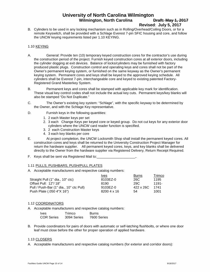
University of North Carolina Wilmington Wilmington, North Carolina Draft: May 1, 2017 Revised: July 5, 2017
Facilities Guide UNCW Page 10 of 14 9/18/2017
B. Cylinders to be used in any locking mechanism such as in Rolling/Overhead/Coiling Doors, or for a remote Keyswitch, shall be provided with a Schlage Everest 7-pin SFIC housing and core, and follow the UNCW keying requirements listed per 1.10 KEYING.
1.10 KEYING A. General: Provide ten (10) temporary keyed construction cores for the contractor’s use during
the construction period of the project. Furnish keyed construction cores at all exterior doors, including the cylinder dogging at exit devices. Balance of locks/cylinders may be furnished with factory produced plastic plugs. Construction control and operating keys and cores shall not be part of the Owner’s permanent keying system, or furnished on the same keyway as the Owner’s permanent keying system. Permanent cores and keys shall be keyed to the approved keying schedule. All cylinders shall be Everest 7-pin, interchangeable core and keyed to existing patented Factory-Registered Grand Masterkey System.
B. Permanent keys and cores shall be stamped with applicable key mark for identification. These visual key control codes shall not include the actual key cuts. Permanent keys/key blanks will also be stamped “Do Not Duplicate.”
C. The Owner’s existing key system: “Schlage”, with the specific keyway to be determined by the Owner, and with the Schlage Key representative.
D. Furnish keys in the following quantities: 1. 2 each Master keys per set 2. 3 each Change Keys per keyed core or keyed group. Do not cut keys for any exterior door
cylinders where the UNCW card reader function is specified. 3. 2 each Construction Master keys 4. 3 each key blanks per core
E. At project completion, the UNCW Locksmith Shop shall install the permanent keyed cores. All construction cores and keys shall be returned to the University Construction Project Manager for return the hardware supplier. All permanent keyed cores, keys, and key blanks shall be delivered directly to the Owner from the hardware supplier via Registered Delivery, Return Receipt Required.
F. Keys shall be sent via Registered Mail to:____________________,.
1.11 PULLS, PUSHBARS, PUSH/PULL PLATES A. Acceptable manufacturers and respective catalog numbers:
Ives Burns Trimco Straight Pull (1" dia., 10" ctc) 8103EZ-0 26C 1195 Offset Pull: 12”/ 18” 8190 29C 1191- Pull / Push-Bar (1" dia., 10" ctc Pull) 9103EZ-0 422 x 26C 1741 Push Plate (.050 4"X 16") 8200 4 x 16 54 1001
1.12 COORDINATORS A. Acceptable manufacturers and respective catalog numbers:
Ives Trimco Burns COR Series 3094 Series 7600 Series
B. Provide coordinators for pairs of doors with automatic or self-latching flushbolts, or where one door
leaf must close before the other for proper operation of applied hardware.
1.13 CLOSERS A. Acceptable manufacturers and respective catalog numbers (for exterior and corridor doors):

University of North Carolina Wilmington Wilmington, North Carolina Draft: May 1, 2017 Revised: July 5, 2017
Facilities Guide UNCW Page 11 of 14 9/18/2017
LCN 1 4011 / 4111 EDA
B. Provide extra heavy duty arm (EDA) when closer is to be installed using parallel arm mounting. All closers shall be handed.
C. Closers shall use high strength cast iron cylinders, forged main arms, and 1 piece forged steel pistons.
D. Closers shall utilize a stable fluid withstanding temperature range of +120deg F to -30deg F without seasonal adjustment of closer speed to properly close the door. Closers for fire-rated doors shall be provided with temperature stabilizing fluid that complies with standards UL10C.
E. Unless otherwise specified, all door closers shall have full metal covers and separate adjusting valves for sweeps, latch, and backcheck.
F. Provide closers for all labeled doors. Provide closer series and type consistent with other closers for similar doors specified elsewhere on the project.
G. Provide closers with adjustable spring power. Size closers to insure exterior and fire rated doors will consistently close and latch doors under existing conditions. Size all other door closers to allow for reduced opening force not to exceed 5 lbs.
H. Install closers on the room side of corridor doors, stair side of stairways and interior side of exterior doors.
I. Closers shall be furnished complete with all mounting brackets and cover plates as required by door and frame conditions, and by adjacent hardware.
J. Closers shall have thirty-year manufacturer’s warranty.
K. Pressure Relief Valve, PRV, are not acceptable.
L. Application criteria: 1 Unless otherwise specified, mount all closers parallel arm.
1.14 LOW ENERGY ELECTRO-MECHANICIAL AUTOMATIC OPERATORS A. Acceptable manufacturers and respective catalog numbers:
LCN 1 Electro-Hydraulic Operator 4630/4640 series
B. Provide automatic operators as specified in hardware groups. Provide complete with drop plates,
brackets, or adapters for arms as required to suit details.
C. Provide wall-mounted actuator switches by the same manufacturer as the operator. Actuators shall be weather-resistant type at exterior applications.
D. Provisions in the control box shall provide control (inputs and outputs) for: electric strike delay, auxiliary contacts, sequential operation, fire alarm systems, actuators, sensors.
E. The operator shall provide a power shut-off switch to the operator control box.
1.15 KICK PLATES AND MOP PLATES A. Furnish protective plates as specified in hardware groups.

University of North Carolina Wilmington Wilmington, North Carolina Draft: May 1, 2017 Revised: July 5, 2017
Facilities Guide UNCW Page 12 of 14 9/18/2017
B. Where specified, provide 8" kick plates, 36" armor plates, and 4" mop plates. Unless otherwise specified, metal protective plates shall be .050" thick.
C. Protective plates shall be 2" less door width, or 1" less door width at pairs. All protective plates shall be beveled 4 sides and have counter sunk screw holes. Protection plates over 16" shall not be provided for labeled doors unless specifically approved by door manufacturers listing.
D. Where required by adjacent hardware, protection plates shall be factory drilled for cylinders or other mortised hardware.
E. Application: Provide armor plates for loading dock doors, cafeteria doors, exterior mechanical rooms, riser and pump rooms, field house and press box doors, and concession stands.
1.16 WALL STOPS AND HOLDERS A. Acceptable manufacturers and respective catalog numbers:
Ives Hager Burns 1 Wrought Convex Wall Bumper WS406CVX 232W 570 2 Wrought Concave Wall Bumper WS406CCV 236W 575 3 Extended Wall Stop WS11/WS11X 255W 530 4 Extended Wall Stop WS33/WS33X **** **** 5 Automatic Wall Holder WS40 254W 533
B. Furnish a stop or holder for all doors.
C. Where wall stops are not applicable, furnish floor stops.
D. Do not provide holder function for labeled doors.
1.17 MAGNETIC HOLD OPENS A. Acceptable manufacturers and respective catalog numbers:
LCN ABH Rixson 1 Wall Holder with Metal Housing SEM 7800 2000 990 Series
B. Magnetic holder's housing and armature shall be constructed of a die cast zinc material.
C. Furnish at Stairways and in Corridors as required.
1.18 WEATHERSTRIP, GASKETING A. Acceptable manufacturers and respective catalog numbers:
Zero 188s NGP 5050 Reese 797
B. Provide drip cap for all exterior HM frames, unless positioned under a canopy.
1.19 THRESHOLDS A. Acceptable manufacturers and respective catalog numbers:
Zero NGP Reese 1 Saddle Thresholds 655 425 S205 2 Panic Type Thresholds 65A 896A S486A 3 Interlocking Threshold 74A 442-5 T550
B. Hardware supplier shall verify all finish floor conditions and coordinate proper threshold as required to insure a smooth transition between threshold and interior floor finish.
C. Threshold Types:

University of North Carolina Wilmington Wilmington, North Carolina Draft: May 1, 2017 Revised: July 5, 2017
Facilities Guide UNCW Page 13 of 14 9/18/2017
1. Unless otherwise specified, provide saddle threshold similar to Zero 655A for all exterior openings with an interior floor finish less than or equal to 1/4" in height.
2. Unless otherwise specified, provide half saddle threshold similar to Zero 1674 for all exterior openings with an interior floor finish greater than 1/4" in height. Threshold height shall match thickness of interior floor finish.
1.20 DOOR POSITION SWITCHES A. Acceptable manufacturers and respective catalog numbers:
GE Schlage Electronics
1 Concealed 1078C 679 series
1.21 KEY CABINETS A. Acceptable manufacturers and respective catalog numbers:
Lund Telkey 1 2600 Series CDF
Series B. Furnish 1 each model 2600 series key cabinet with a capacity 1.5 times the number of key sets.
C. Provide one key cabinet with at least one hook for each key set, plus additional hooks for 50% expansion.
D. Furnish key cabinet complete with cam lock, permanent key tags, and change key cards.
E. Hardware supplier shall prepare all key change index records, tag all keys and place permanent file keys in cabinet.
1.22 ELECTRIFIED HARDWARE FUNCTIONS A. General: operation of the card reader access control system shall be managed by the UNCW
Physical & Access Department. Card readers, credentials, monitoring, alarms shall be furnished under Division 28. Refer to the current UNCW Physical Security & Access Standards.
B. The door function shall be as specified in the Finish Hardware Sets. Openings shall be furnished with all materials listed to provide the security function and control required by the Owner. All hardware sets with electrified hardware shall include an operational description. A riser wiring diagram shall be required as part of the HW Set for electrified functions.
C. Typical electrified hardware applications: 1. Entry Door with card reader and handicap operator. The following products shall be
specified: a. Electrified exit device: QEL-RX-LC 98-NL/NL-OP. Power supply as PS914-4RL.
Electric hinge as Continuous: EPT or TW8 x Rem Panel. As Butt Hinge: TW-8. Auto-operator with actuators. Door positon switch. Card reader by Div. 28.
2. Entry Door with card reader. The following products shall be specified: a. Electrified exit device: QEL-RX-LC 98-NL/NL-OP. Power supply as PS914-4RL.
Electric hinge as Continuous: EPT or TW8 x Rem Panel. As Butt Hinge: TW-8. Door positon switch. Card reader by Div. 28.
3. Interior Door with card reader: The following products shall be specified: a. Electric Mortise Lock: L9092BD-EU x L283-392 (RX). Power supply as PS914-
4RL. Electric hinge as butt hinge: TW-8. Door position switch. Card reader by Div 28.

University of North Carolina Wilmington Wilmington, North Carolina Draft: May 1, 2017 Revised: July 5, 2017
Facilities Guide UNCW Page 14 of 14 9/18/2017
D. Card reader equipment shall be provided and installed by the Division 28 subcontractor. The auto-
operators, door position switch, electrified exit devices, electrified locks, electric hinges, shall be installed and terminated by the GC and/or the Hardware Installer. UNCW Physical Security and Access Division shall install required bridge wiring after the door operator is installed. All electrical applications specified shall be confirmed by review with the UNCW Project Manager and the Physical security and Access Department.
E. All exterior building entry doors shall be specified with one or more of the above listed electrical function, or the openings shall be specified with provision for future card readers and electrified hardware. The Hardware Consultant shall request verification of the required electrical hardware entry functions with the Owner’s Physical Security and Access Technician. Provisions for future electrical function at entry doors shall be specified on the project’s electrical drawings and in Division 26/28 in the Project Manual. The Hardware Consultant shall include reference to future electrical applications in the Hardware Sets only as acknowledgement only of the future electric application.
1.23 FINISHES AND BASE MATERIALS A. Unless otherwise indicated in the hardware groups or herein, hardware finishes shall be applied over
base metals as specified in the following finish schedule: HARDWARE ITEM BHMA FINISH AND BASE MATERIAL
1. Butt Hinges: Exterior, or Non-Ferrous
630 (US32D)
2. Butt Hinges: Interior 652 (US26D) 3. Continuous Hinges 628 (US28) 4. Flush Bolts 626 (US26D) 5. Exit Devices 626 (US26D) 6. Locks and Latches 626 (US26D) 7. Pulls and Push Plates/Bars 630 (US32D) 8. Coordinators 600 (Prime painted or mill alum.) 9. Closers 689 (Powder Coat Aluminum) 10. Protective Plates 630 (US32D) 11. Wall Stops and Holders 630 (US32D) 12. Thresholds 628 (Mill Aluminum) 13. Weather-strip, Sweeps Drip Caps Aluminum Anodized 14. Magnetic Holders Sprayed Aluminum 15. Magnetic Locks 628 (US28) 16. Miscellaneous 626 (US26D)
1.24 MISCELLANEOUS A. Furnish 3-5 extra Schlage Everest keyed cores as attic stock for each project.
END OF SECTION

09 00 00 Finishes This document is a guideline and cannot be used as a final specification
Issue September 2017 Page 1 of 5
09 00 00 Finishes - General Requirements
Part 1: General
1.01 The University standard exterior paint color is “Palais White.” (see section 09 91 20 Painting)
1.02 Ceilings A. Where possible all ceilings are to be suspended ceilings.
1.03 Concrete Floors and CMU walls A. Interior concrete floors shall not remain unfinished. A clear sealant is required as a
minimum. B. Interior CMU walls exposed to the room’s interior shall not remain unfinished.
Part 2: Gypsum Board
2.01 Drawings: A. Indicate on drawings the following information related to Gypsum Board:
1. Extent of each kind of gypsum board construction: a. Thickness of gypsum board and number of layers for each different application, to
the extent not universally specified. b. Exceptions to standard requirements specified in text. c. Locations where foil-backed gypsum board is required (if any). d. Locations where water-resistant backing board is required (if any). e. Locations where moisture and mold resistant is required. f. Locations where exterior gypsum soffit board is required (if any). g. Locations where z-furring strips are required, with thickness of insulation indicated. h. Locations of resilient furring. i. Locations of metal furring channels.
2. Locations and extent of fire-resistant –related drywall assemblies, including U.L. Design numbers. Requirement in text requires each such assembly to be constructed with Type “X” gypsum board.
3. Details of framing for door, window and other openings. 4. Special details where normal manufacturer’s details are not applicable. 5. Sound control and isolation details, particularly edge trim and sealants or gaskets. 6. Steel framing details, including those for door and other openings; indicate partition and
wall thickness and exceptions to standard requirements for stud sizes and spacing; correlate with section text.
7. Details of framing for suspended ceiling construction, if not fully specified.

09 00 00 Finishes This document is a guideline and cannot be used as a final specification
Issue September 2017 Page 2 of 5
8. Locations requiring sound attenuation blankets or other acoustical treatment. Include STC ratings required, or notations to comply with specified sound control requirements.
9. Whether partitions pass through ceilings to structure above, and if so, whether drywall facings are to be complete (and with joints treated).
a. Trim accessories, to the extent not universally specified, including control joints and expansion joints, of types requiring finishing compound for smooth, finished appearance.
10. Supplementary framing, blocking, etc., for fixture support and for support of ceiling runners (tracks) offset from beams or metal deck flutes or both.
11. Extent of each kind of gypsum board shaft wall construction. 12. Locations and extent of each fire-resistance rated gypsum board shaft system assemblies,
including UL Design or GA File Numbers. 13. Details showing supplementary fire protection for items penetrating shaft-wall
construction. 14. Coordination with spayed-on fireproofing, stair systems, elevator entrances, building
structure, etc. 15. Types of applied finishes on room-side of work.
2.02 Specification Requirements: See section 09 29 00 Gypsum Board
2.03 Ceiling Access: A. Adequate access panels/doors must be provided to all concealed mechanical/electrical
equipment requiring maintenance (i.e. ballasts, valves, HVAC controls, etc.)
Part 3: Tile
3.01 (Reserved)
Part 4: Acoustical Panel Ceilings
4.01 General: A. Ceiling grids are to 2’ x 2’. The ceiling tile is to be tegular-edged. The grid rail is to be 15/16
inch in width. The color of the ceiling tile is white.
4.02 Drawings: A. Indicate on drawings the following information related to Acoustical Panel Ceilings:
1. Extent of acoustical panel ceilings. Show additional details for further delineation conditions at changes in ceiling elevation, such as soffits, fasciae, drapery pockets, and beams.
2. Layout of units showing size, placement, and direction of long dimensions of units; layout of border, transition, and special accent areas; and exposed suspension members.

09 00 00 Finishes This document is a guideline and cannot be used as a final specification
Issue September 2017 Page 3 of 5
3. Location of other ceiling features, such as light fixtures, air diffusers, partition pockets, and sprinklers, in relation to acoustical ceiling panel layout.
4. Areas where units are integral with UL-related construction, including hourly rating required and UL design numbers.
5. High-Humidity areas, to review special materials and finishes as specified. 6. Areas where hold-down clips are required, if not uniformly required. 7. Variations in structural classification of suspension system, if any. 8. Special bracing in the ceiling plenum to accommodate lateral partition loads and similar
considerations.
4.03 Specifications: A. See section 09 51 23 Acoustical Panel Ceilings.
Part 5: Resilient Flooring
5.01 General: A. Resilient flooring consists of vinyl tile flooring and related accessories. Corridors, fire stair
lobbies and landings, classrooms, teaching and research laboratories, kitchens, photocopy rooms, storage rooms, mail rooms, recycling rooms, etc. flooring is to be vinyl tile.
B. Exceptions are to be approved in by the University Architect. C. At this time, the following addresses only tile flooring and some accessories.
5.02 Drawings: A. Indicate on drawings the following information related to resilient flooring:
1. Location and extent of each type of resilient flooring, special patterns, borders, and cutouts.
2. Location, extent and junction details of accessories, as required. 3. Schedule of sizes, types, colors, and patterns on a room-by-room basis. 4. Indicate direction of grain; note grain in one direction, not “checkerboard” pattern.
5.03 Specifications: See section 09 65 00 Resilient Flooring.
Part 6: Carpet
6.01 General: A. Carpet is to be limited to offices, conference rooms, seminar rooms, and lecture hall flooring.
6.02 Drawings: A. Indicate on drawings the following information related to Carpet:
1. Extent (layout) of each type of carpet, either by notes on plans or by room finish schedules.

09 00 00 Finishes This document is a guideline and cannot be used as a final specification
Issue September 2017 Page 4 of 5
2. Locations of different colors and patterns of the same carpet. 3. Direction of pattern established by seaming plan. Notes on installation methods. Seaming
layout shall enable future replacement, especially in open areas and traffic paths. 4. Seaming shall run parallel to major traffic flow whenever possible. 5. Direction of pile. 6. Carpet joint details at access doors, expansion joints, and similar locations, unique edges. 7. Areas where different types of cushion are required. 8. Extent of each type of carpet cushion, either by notes, plans or room finish schedules.
6.03 Specifications: See Section 09 68 00 Carpeting
Part 7: Special Flooring
A. (Reserved)
Part 8: Painting
8.01 General: A. Work referred to herein is limited, at this time, to interior painting systems of the types
usually applied over wall and ceiling surfaces of those building materials generally used in commercial/institutional projects; these materials are usually known as “Architectural Coatings”, as opposed to “High Performance Coatings”.
B. A list of the manufacturer, type and specific color used at each location shall be provided to the Office of Facilities Physical Plant at Occupancy.
C. The University does not desire large amounts of left over materials e.g. tile, carpet, etc. but especially paint. Long-term storage space is at a premium and generally not available.
D. See section 09 91 20 Painting.
8.02 Paint Finishes: A. Many factors must be considered in making a selection between flat and gloss sheen, between
a latex and alkyd oil paint. The following factors must be considered prior to specifying a paint finish: 1. Substrate material and surface. 2. Function and environment of the area to be finished. 3. Texture gloss desired. 4. Washability/durability desired. 5. Abrasion resistant properties required. 6. Chemical resistance necessary. 7. Color hue and value desired.
09 00 00 Finishes This document is a guideline and cannot be used as a final specification
Issue September 2017 Page 5 of 5
8.03 Drawings: A. Indicate on drawings, schedule and/or specifications the following information related to
Painting: 1. Extent of surfaces to be painted. 2. Texture and gloss of finishes. 3. Colors of various finishes. 4. Number of coats.
Part 9: Wall Coverings
9.01 (Reserved)

09 29 00 Gypsum Board This document is a guideline and cannot be used as a final specification
Issue September 2017 Page 1 of 2
09 29 00 Gypsum Board
Part 1: General
1.01 Finish levels: A. Where exposed to view, all gypsum board surfaces shall be Level 5. B. Exceptions:
1. Utility rooms such as but not limited to Mechanical, Electrical, and Telephone Data, shall be a Level 4 finish.
1.02 Thickness: A. 5/8” at interior vertical wall surfaces. B. 1/2” at interior horizontal surfaces. (Sag-resistant gypsum board.)
Part 2: Exterior Walls
2.01 Provide Moisture and Mold Resistant gypsum board on the interior side of all exterior walls.
Part 3: Interior Walls
3.01 Provide Moisture and Mold Resistant fiberglass gypsum board on any interior wall that may frequently get wet. A. Basis of Design Product: “DensShield” by Georgia-Pacfic (GP)
3.02 Provide specialty sound-absorbing gypsum board on all walls between classrooms and between classrooms and any adjoining, noise producing spaces like mechanical rooms, conference rooms, offices, etc.
3.03 Provide impact-rated gypsum board in high traffic areas such as corridors, lobbies, and fire stairs. A. Ensure that gypsum board specifications address the following provisions:
1. Standard Thickness Gypsum Board: 5/8” thick gypsum board standard for all single-layer applications.
2. Standard Gypsum Board Partitions: Generally, and unless specifically required otherwise, provide standard partitions to divide spaces constructed of: 3-5/8” x 20 gauge metal studs at 16” o.c.
3. Acoustical insulation and/or fire-related gypsum board may be specified (scheduled) for above described “standard” partition, as function requires.
3.04 Metal Trim: A. Specify corner beads, casing beads and control joint trim of the type requiring joint
compounds installed to the edge bead to result in a smooth finished corner.

09 29 00 Gypsum Board This document is a guideline and cannot be used as a final specification
Issue September 2017 Page 2 of 2
1. Note: Reveal type “J” beads, with exposed return flange, requiring no finishing compound (such as USG #400 Series) are not acceptable to UMAB in any location that remains visible upon completion of work. Specify, in lieu thereof, products similar to USG #200 or #800 Series trim.
3.05 Metal plate reinforcing: A. Specify or indicate horizontal galvanized plate(s) 6” width x16 gauge x length required (in
maximum unit lengths of 8 feet each), screw or rivet-attached to face(s) of metal studs in gypsum board partitions, to provide reinforced backing for fastening cabinet, counters, shelving units and other wall –mounted items. Coordinate plans and identify locations, extent, and height to center-line of plate(s) throughout.

09 29 50 Polymer Modified GFRC This document is a guideline and cannot be used as a final specification
Issue September 2017 Page 1 of 5
09 29 50 Polymer Modified GFRC (PM-GFRC)
Part 1: Architectural Fabrications for Exterior Use
1.01 PM-GFRC products to be used for exterior building elements such as cornices, balusters, pediment, columns, architectural door frames and other similar items.
1.02 The PM-GFRC product will be painted. Appearance of the finish installation must be equal to or better than the traditional material that would have been used.
1.03 Field finished joints and seams shall not be visible except for expansion joints. Continuous joints and seams shall be flush and match in texture.
1.04 Exposed fiber reinforcement is not acceptable.
1.05 Fasteners shall be counter sunk and filled.
1.06 No field modifications of precast fabrications.
1.07 The fabrication and installation of the PM-GFRC and its backup assembly shall be certified by a NC licensed engineer for compliance with code requirements for wind loads.
1.08 Assembly of PM-GRFC fabrications and backup shall be designed to resist cracking at joints and seams.
1.09 Shop Drawings: Show fabrication and installation details for GFRC-PM components including the following: 1) Structural analysis data signed and sealed by the qualified professional engineer responsible
for their preparation. 2) Casting elevations, sections, and dimensions shall include:
A. Back-up and blocking framing. B. Fastening of casting to back-up. C. Fastening of back-up to structure.
3) Size, location, and details of joints and connections between cornice casting sections. 4) Erection sequence for special conditions. 5) Relationship to adjacent materials. 6) Description of loose, cast-in, and field hardware.
Part 2: Warranty
2.01 Manufacturer 1-year warranty.

09 29 50 Polymer Modified GFRC This document is a guideline and cannot be used as a final specification
Issue September 2017 Page 2 of 5
Part 3: Design Standard Samples of Original Campus Trimwork that would be reproduced in PM-GFRC.
3.01 Column and Cornice Details from Alderman Hall
Cornice Detail from Sheet #11 Alderman Hall
All wood assembly shown. See use of PM-GFRC cornice on next page.
Column Detail from Sheet #12 Alderman Hall
“Temple of the Winds” fluted column shown

09 29 50 Polymer Modified GFRC This document is a guideline and cannot be used as a final specification
Issue September 2017 Page 3 of 5
3.02 Cornice & Parapet Detail from Alderman Hall

09 29 50 Polymer Modified GFRC This document is a guideline and cannot be used as a final specification
Issue September 2017 Page 4 of 5
3.03 Elevation from Alderman Hall

09 29 50 Polymer Modified GFRC This document is a guideline and cannot be used as a final specification
Issue September 2017 Page 5 of 5
3.04 Elevation from Alderman Hall

09 51 23 Acoustical Panel Ceiling This document is a guideline and cannot be used as a final specification
Issue September 2017 Page 1 of 1
09 51 23 Acoustical Panel Ceiling
Part 1: General
1.01 Determine that acoustical panel ceilings specifications address the following provisions in their correct specification section format locations: A. Submittals:
1. Specify requirements for submission of coordination drawings for reflected ceiling plans drawn accurately to scale ¼” = 1’-0” indicating penetrations, light fixtures, HVAC outlets and inlets, speakers, sprinkler heads, special moldings at walls, columns, and relationship with adjoining materials and planes.
B. Extra Materials: 1. Specify delivery of extra stock of suspension system components and acoustical panels in
a quantity not less than 2% of the amount installed.
Part 2: Materials:
2.01 Basis of Design Product shall be “ClimaPlus” series by USG.

09 65 00 Resilient Flooring This document is a guideline and cannot be used as a final specification
Issue September 2017 Page 1 of 1
09 65 00 Resilient Flooring
Part 1: General
1.01 Ensure that resilient flooring specifications address the following provisions in their correct specification section format locations: Architects to review the following: A. Extra stock: Specify not less than one box for each 50 boxes, or fraction thereof, for each
type, color, pattern, and size installed. B. Standard size and gauge for vinyl-composition tile at UMAB is 12” x 12” x 1/8” gauge. As
manufactured by Amtico or Farkett or approved equal. C. Specify underlayments over existing wood floors or subfloors as ¼” exterior grade plywood
or 7/32” tp ¼” Luaun plywood; ‘Masonite’ is not acceptable.
1.02 Vinyl Cove Base: A. 4” high, covered over resilient flooring, toeless at carpet flooring. Colors selection is
generally made from brown, black, tan and gray.
1.03 Vinyl transition strips/reducer: A. 1/8” or ¼” gauge B. Color: black or brown.

09 66 23 Resinous Matrix Terrazzo This document is a guideline and cannot be used as a final specification
Issue September 2017 Page 1 of 1
09 66 23 Resinous Matrix Terrazzo Flooring
Part 1: Thin-set, epoxy-resin terrazzo flooring
1) Thickness: 3/8” (9.5 mm) nominal. 2) Pre-cast Stair Treads and Risers units shall be fabricated using the same material as the floor.
A. Thickness: ¾” 3) Pre-cast Floor Base units shall be fabricated using the same material as the floor.
A. Minimum 3/8-inch thick. Precast units to be cast in maximum lengths possible, but not less than 36 inches.
i. Type: Coved bottom. ii. Outside Corner Units: With finished returned edges at outside corner. iii. Inside Corner Units
4) Moisture Vapor Retarding Primer. Provide unit cost for 100% coverage. 5) Crack Isolation Membrane. Provide unit cost for 10% coverage. 6) Floor Finish and Polishing: Grind and Polish Epoxy-Resin Terrazzo up to the use of 1000 grit
pads. The surface shall have a uniform reflective appearance showing no high or low sheen variances.
1.02 Manufacturer Qualifications: 1) Terrazzo materials shall be provided by a manufacturer who is a member of NTMA.
1.03 Installer Qualifications: 1) Engage an installer who is a contractor member of NTMA. 2) Engage an installer who is certified in writing by terrazzo manufacturer as qualified to install
Manufacturer’s products. 3) Engage a terrazzo contractor with at least five (5) years of satisfactory experience in
installation of epoxy terrazzo. Terrazzo contractor shall demonstrate experience during last five (5) years of at least (5) projects of comparable scope and complexity of at least 50 percent of the total square footage of this project.
Part 2: Testing of Polished Floor Finish
2.01 Floor finish shall be tested using a recognized testing method. A coefficient of friction of .50 or more is required.

09 86 00 Carpeting This document is a guideline and cannot be used as a final specification
Issue September 2017 Page 1 of 2
09 86 00 Carpeting
Part 1: General
1.01 Ensure that carpet specifications address the following provisions in their correct CSI section format locations: A. Carpet Option #1 Data: B. Basis of Design: Collins & Aikman, “Guardian Plus RS”, or products of other
manufacturers subject to compliance with these requirements: 1. Face Construction: Tufted level loop.
a. Tuft must be warrantable wet or dry. 2. Face Fiber: Dyed nylon similar to Antron II by Dupont 3. Face Weight: Minimum of 26 oz./sq.yd. 4. Performance Characteristics: Soil and stain resistant. 5. Static resistant. 6. Colorfast. 7. Treated for resistance to bacteria, mold, and mildew.
1.02 Carpet Option#2 Data: A. Basis of Design: Lees Commercial Carpet, “Uni-Bond”, Lifetime warranty B. Padding:
1. Basis of Design: Collins & Aikman, “Power Bond RS”, or approved equal. C. Specify underlayments over existing wood floors or subfloors as ¼” exterior grade plywood
or 7/32” to ¼” Luaun plywood; ‘Masonite’ is not acceptable.
1.03 Vinyl Cove Base: A. 4” height, toeless at carpet flooring.
1.04 Vinyl Reducer Strip: A. Flexco Co., “Edge Guard #79”, 3/8” undercut, 12’ sections; or products of other
manufacturers complying with product noted.
1.05 Installation A. New Carpet:
1. Direct-glue method. (UMAB does not approve double glue installations).

09 86 00 Carpeting This document is a guideline and cannot be used as a final specification
Issue September 2017 Page 2 of 2
1.06 Warranty: 15 years, non-prorated, in writing and notarized A. Warranty Standards – carpet must not:
1. Seam failure – wet or dry 2. Zippering – caused by seam failure or tuft failure 3. De-lamination of backing – wet or dry whether caused by steam cleaning, wet cleaning,
flooding, or non use of chair pads 4. Carpet pile or backing failure on stair installation
B. In addition to manufacturer’s fiber wear warranty, carpet manufacturer must warrant face fiber and cushion resiliency (crushing) not to exceed 15% over 15 years of 1% per year.

09 91 20 Painting This document is a guideline and cannot be used as a final specification
Issue September 2017 Page 1 of 2
09 91 20 Painting
Part 1: Exterior
1.01 Trimwork: Exterior Latex, Flat A. Color: The standard exterior color is “Palais White” SW #2429 by Sherwin Williams.
Part 2: Interior
2.01 Recommended finishes for given functional spaces: A. Offices:
1. Latex: flat sheen. B. Corridors:
1. Velvet acrylic: low sheen. 2. Acrylic latex semi-gloss.
C. Janitor’s Closets: 1. Latex semi-gloss.
D. Toilets: 1. Latex semi-gloss.
E. Classrooms: 1. Velvet acrylic; low sheen. 2. Latex semi-gloss.
F. Stairwells/Stairs: 1. Stair tread colors shall be carefully selected to provide adequate contrast and allow for
discernment of stairs when ascending and descending. 2. Carpet shall not be used in stairwells. 3. Latex semi-gloss.
G. Laboratories: 1. Alkyd semi-gloss. 2. Modified epoxy. 3. Urethane fortified high gloss enamel.
H. Animal Research Facilities: 1. Modified epoxy. 2. Two-component polyamide epoxy.
I. Trim: 1. Latex semi-gloss.

09 91 20 Painting This document is a guideline and cannot be used as a final specification
Issue September 2017 Page 2 of 2
2. Latex, high-gloss. J. Mechanical Equipment/Piping:
1. Alkyd semi-gloss. 2. Synthetic gloss enamel.
K. Mechanical Rooms: 1. Telecommunications terminal boards shall be painted with a fire retardant type of paint.
L. Common Areas: 1. Shall be finished with a semi-gloss paint.
2.02 Colors: A. Coordinate colors with the office of Facilities to ensure that the preferred colors used
throughout the campus are selected.
2.03 Warranty: A. All paint materials and workmanship are subject to a 2-year (24 months) period from the date
of Final Acceptance or Substantial Completion (whichever occurs first), as noted in the General Conditions.
2.04 Manufacturers, Quality Line: A. Provide paint materials as manufactured by Duron Paint Mfg. Co., of the top quality line for
each paint type, or materials of other manufacturers subject to compliance with these requirements.

10 11 00 Visual Display Surfaces This document is a guideline and cannot be used as a final specification
Issue September 2017 Page 1 of 2
10 11 00 Visual Display Surfaces
Part 1: Markerboards:
1.01 Face: Porcelain enamel on steel, laminated to core. A. Porcelain Enameled Steel Sheet: ASTM A 424, Type I, Commercial Steel, with fired-on
vitreous finish. B. Color: As selected from manufacturer’s full range. C. Metal Face Sheet Thickness: 0.024 inch (24 gage).
1.02 Core: Particleboard, manufacturer’s standard thickness, laminated to face sheet.
1.03 Backing: Aluminum foil, laminated to core.
1.04 Frame: Extruded aluminum, with concealed fasteners. A. Frame Profile: 5/8 inch mitered corner profile B. Frame Finish: Anodized, natural.
1.05 Accessories: Provide display rail, marker tray and map hooks.
1.06 Basis of Design: “LCS” Series manufactured by Claridge.
Part 2: Tackboards: Fabric laminated to cork.
2.01 Cork Thickness: 7/32 inch.
2.02 Fabric: Vinyl coated fabric.
2.03 Color: As selected from Manufacturer’s full range.
2.04 Backing: Hardboard, ¼ inch thick, laminated to tack surface.
2.05 Frame: Extruded aluminum, with concealed fasteners. A. Frame Profile: Standard 5/8 inch mitered corner profile B. Frame Finish: Anodized, natural.
2.06 Basis of Design: “Fabricork” as manufactured by Claridge.
Part 3: Accessories
3.01 Chalk Tray: Aluminum, manufacturer’s standard profile one length piece for markerboard; molded ends; concealed fasteners, same finish as frame.

10 11 00 Visual Display Surfaces This document is a guideline and cannot be used as a final specification
Issue September 2017 Page 2 of 2
3.02 Mounting Brackets: Concealed.

10 14 00 Interior & Exterior Signage This document is a guideline and cannot be used as a final specification
Issue September 2017 Page 1 of 11
10 14 00 Signage – Exterior and Interior
Part 1: Interior Signs
1.01 General A. Room Identification and Wayfinding - All campus facilities utilize a uniform methodology
for numbering building rooms and spaces and must comply with a campus standard for interior signs and directories. See Section 01 00 60 Room Numbering and Wayfinding.
1.02 Design Guidelines A. All building rooms and spaces are to be numbered consistent with UNCW’s room numbering
methodology. See Section 00710 for additional information. Room numbers are to be established during the Design Development stage consistent with this methodology and continued through Construction Document and Construction phases.
B. Interior signage shall comply with UNCW Interior Signage Standards. C. The designer shall meet with the UNCW user group, and the Project Manager to develop the
signage package during Construction Document development. During construction, the designer shall coordinate with the Contractor and Construction Project Manager and the user group to re-verify the signage package prior to release for fabrication and installation.
1.03 Special Signs A. ADA: All signage on the project that falls under the jurisdiction of the American with
Disabilities Act is to be provided as required to comply with all applicable requirements of ADA. It is the responsibility of the contractor and the signage manufacturer to ensure that all signage complies with ADA.
1.04 Construction and Materials A. Provide signage manufactured by a photomechanical (media blast) etching process, leaving
the copy and braille raised. The plaque is then laminated to a 1/8” opaque acrylic base cut to size and finished with a professional coat of acrylic polyurethane enamel in a selected color. Signs are to be unframed with a square corner with beveled edges.
B. Braille and text are to be raised 1/32”. C. Room Numbers are to be 1” high D. Text is to be 5/8” high on all signs except Sign Type #5. On Sign Type #5 the text is to be 1”
high. E. Letter Style is to be: Standard Bold Condensed – Upper Case Letters F. Finished signs are to be ¼” thick G. Edge Treatment: Beveled H. The signs are to have a square corner with no border. I. The color of the sign is to be silver with black letters, graphics and braille. J. The Grip-Smart Strip is to be clear anodized aluminum finish with black plastic end caps.

10 14 00 Interior & Exterior Signage This document is a guideline and cannot be used as a final specification
Issue September 2017 Page 2 of 11
1.05 Submittals A. The contractor shall submit a sample of each type of sign in the specified color and size and a
sample of the Grip-Strip showing its attachment to the appropriate sign type. B. Prior to the installation, the contractor shall supply in duplicate the signage finish schedule
and shop drawings showing the colors, words, numbering and other information to be included on the signage as it is to be installed.
1.06 Installation A. The contractor is to install the signage in accordance with the drawings, these specifications,
approved shop drawings and in accordance with manufacturer’s printed instructions. Include all accessories to provide a proper installation. Work is to be level, plumb and in true plane. Work is to be secure and rigid. Installation accessories shall be furnished by the signage manufacturer. Do not use installation materials from any other source. Signs adhered to glass shall have a blank plate attached to the back of the glass so that the attaching tape or other method is not visible. The color of the blank plate is to match the sign color. The size of the blank plate is to match the size of the sign.
B. The contractor shall supply and install all the graphic inserts (pre-cut and printed) for the Type 1 and Type 2 signs. The inserts are to be on paper.
C. Attachment: Per manufacturer recommendation, must be easily removable without damage. D. Signs are to be mounted so that they are ADA compliant. E. The Grip-Strip Sign is to be mounted to the plastic sign and not directly to the wall.Guarantee F. Any signs that do no remain securely bonded to the substrate for a period of 1 year after
acceptance of the project are to be removed and properly reinstalled at no additional cost to the owner.
1.07 Manufacturers A. List of UNCW pre-approved manufacturers:
1. Best Sign System 2. Corum Signs 3. ASI Sign System 4. Signature Signs, Inc. 5. 290 Sign System
1.08 Sign Type Usage Schedule
Type 1 Type 1 Type 3 Type 4 A, B&C Type 5 Office Conference Rms Classrooms
Photocopy Rms Reception File Room
Housekeeping Mechanical Hazardous Waste Electrical Telecom/Data
Restrooms Direction Department Signs Information Signs Directories
Note: Type 2 has been omitted.
1.09 See SIGNAGE APPENDIX S1 for dimensions of signs.

10 14 00 Interior & Exterior Signage This document is a guideline and cannot be used as a final specification
Issue September 2017 Page 3 of 11
Part 2: Exterior Signage
2.01 General A. All new building projects and major building renovations require exterior signage. Number
of exterior signs and location of sign to be determined during final design stage.
2.02 Design Guidelines A. All exterior signage shall comply with the UNCW Exterior Signage Standard. B. Color of signs to be: When applied to brick the lettering is white, if applied to white fascia,
the lettering is bronze finish. C. Standard Size:
1. Letters of sign to be ¾” depth, 8” or as directed by PM tall using architectural style – “Prismatic” as manufactured by BFG Industries, Inc. (see Appendix S2)
2. Other Letter Sizes: a. Letter height will be determined by defined wall space available for the text. See
Appendix S2 for average letter width as a space guide. b. Letter distance readability can be determined by chart. (see Appendix S2)
2.03 Quality Assurance A. Manufacturer to have a minimum of 20 years experience in manufacturing letters. B. All letters must be manufactured by one manufacturer and must match existing cast
aluminum letters at UNCW facilities - i.e. BFG No. 754 Architectural (prismatic face) letter style. (see Appendix S2)
C. A qualified sign installer should install letters.
2.04 Products A. Basis of Design: Provide exterior signs by BFG Industries, Inc., 1057 Colite Drive, West
Columbia, SC 19170 or approved equal based upon specification compliance.
2.05 Materials A. Aluminum ingot for cast aluminum letters - No. 443.1 alloy. B. Aluminum extrusion for aluminum sleeve spacers - 6061 or 6063 alloy. C. Aluminum all-thread studs for installation hardware for letters up to 16" in height. D. Stainless steel all-thread studs for installation hardware for letters> 18" in height.
2.06 Finishes A. Natural Satin faces, file finished edges, 2-part hardened acrylic polyurethane clear coat. B. Aliphatic polyurethane enamel equal to DuPont IMRON 3.5 HG paint.
2.07 Mounting Hardware A. Cast aluminum letters have threaded stud bosses for installation stud insertion. B. Letters up to 10" letter height receive 3/16" diameter aluminum studs.

10 14 00 Interior & Exterior Signage This document is a guideline and cannot be used as a final specification
Issue September 2017 Page 4 of 11
C. Letters from 12" letter height up to 16" letter height receive 1/4" diameter aluminum studs. D. Letters greater than 18" letter height receive 1/4" diameter stainless steel studs. E. All letters utilize a STOP NUT and an extruded ALUMINUM SLEEVE SPACER. F. Installation to be performed per MOUNTING DETAIL PM-TYPE K (see Appendix S2). G. Pre-spaced installation paper template required for each set of letters provided. H. Epoxy adhesive required; F-26 Heavy Adhesive by Leech Products, Inc.
2.08 Warranty A. Letters are to be guaranteed for the life of the intended use against defects in manufacturing. B. Letter finish should be guaranteed for 5 years from excessive fading of cracking, peeling, and
delamination of the paint.

10 14 00 Interior & Exterior Signage This document is a guideline and cannot be used as a final specification
Issue September 2017 Page 5 of 11
SIGNAGE
APPENDIX S1

10 14 00 Interior & Exterior Signage This document is a guideline and cannot be used as a final specification
Issue September 2017 Page 6 of 11

10 14 00 Interior & Exterior Signage This document is a guideline and cannot be used as a final specification
Issue September 2017 Page 7 of 11

10 14 00 Interior & Exterior Signage This document is a guideline and cannot be used as a final specification
Issue September 2017 Page 8 of 11

10 14 00 Interior & Exterior Signage This document is a guideline and cannot be used as a final specification
Issue September 2017 Page 9 of 11

10 14 00 Interior & Exterior Signage This document is a guideline and cannot be used as a final specification
Issue September 2017 Page 10 of 11
ELEVATOR SIGNAGE AND MOUNTING

10 14 00 Interior & Exterior Signage This document is a guideline and cannot be used as a final specification
Issue September 2017 Page 11 of 11
SIGNAGE APPENDIX S2

10 21 13 Toilet & Shower Compartments This document is a guideline and cannot be used as a final specification
Issue September 2017 Page 1 of 1
10 21 13 Toilet and Shower Compartments
Part 1: Toilet Compartments
1.01 Door, Panel and Pilaster Construction: Solid phenolic-core panel material with custom decorative laminate facing on both sides fused to substrate during panel manufacture (not separately laminated), and with eased and polished edges. Provide minimum 3/4-inch- thick doors and pilasters and minimum 1/2-inch- thick panels.
1.02 Door and Panel Dimensions A. Door Width: 24 inch. B. Door Width for Handicapped Use: 36 inch, out-swinging.
1.03 Brackets (Fittings): Full-Height (Continuous) Type: Manufacturer's standard aluminum or stainless steel.
1.04 Urinal Screens: Floor and wall mounted.
1.05 Shower Enclosures: Floor mounted, overhead braced.
1.06 Accessories A. Pilaster Shoes: Type 304 stainless steel with No. 4 finish, not less than 0.0312 inch specified
thickness and 3 inches high, concealing floor fastenings. B. Overhead Bracing: Manufacturer's standard continuous, extruded-aluminum head rail with
anti-grip profile and in manufacturer's standard finish. C. Integral shower curtain head rail: Manufacturer’s continuous, extruded aluminum C-channel
rail with nylon glide hook carriers. Provide heavier gauge head rail for longer spans or provide ceiling mounted center support with concealed fastening. Suspend and brace from structure above. Provide flange for supports where they penetrate through ceiling. Finish of all components is to match head rail.
D. Anchorages and Fasteners: Manufacturer's standard exposed fasteners of stainless steel finished to match hardware, with theft-resistant-type heads. Provide sex-type bolts for through-bolt applications. For concealed anchors shall also be stainless steel.
1.07 Hardware: A. All screws and fasteners shall be Stainless steel. B. Pivot hinges, gravity type, adjustable for door close positioning; two per door. C. Door Latch: Slide type with exterior emergency access feature. D. Door strike and keeper with rubber bumper. E. Coat hook with rubber bumper; one per compartment, mounted on door.

11 00 00 Equipment This document is a guideline and cannot be used as a final specification
Issue September 2017 Page 1 of 2
11 00 00 Equipment General Requirements
Part 1: Food Service Equipment:
1.01 (Reserved)
Part 2: Medical Equipment:
2.01 (Reserved)
Part 3: Vacuum Central System:
3.01 Central vacuuming systems will be considered for large areas with fixed seating such as auditoriums and stepped lecture halls.
Part 4: Vending Equipment:
4.01 Vending equipment will be provided by the University. However the Designer must provide for proper locations and required electrical and plumbing service.
Part 5: Laboratory Equipment:
5.01 The Designer is responsible for determining from the users their specific requirements for the equipment for each laboratory. Since laboratories are highly specialized entities, their equipment needs may be highly complex.
5.02 Design responses may at times be substantially influenced by existing equipment in the case of renovations projects.
Part 6: Waste Handling Equipment:
6.01 The University uses the dumpster system for most ordinary types of collection. This system employs the use of metal containers and a packer truck to mechanically list and dump the cans. The truck requires an overhead clearance of approximately twenty-one feet (verify current vehicle used). The approximate gross weight is 15,000 pounds on the front axle and 38,000 pounds on the rear tandem axles. The roads surface shall be of suitable construction to support the vehicle at its maximum loaded weight. The service road to the container shall have a minimum of twelve-foot width, twenty feet at the curves. The trucks require a forty-five foot turning radius.
6.02 It is preferred that the rubbish container be located immediately adjacent to the loading platform of the building at a level providing convenient top loading from the platform. A concrete pad shall be provided for each container. The surface of the concrete pad shall be on a plane parallel to the road

11 00 00 Equipment This document is a guideline and cannot be used as a final specification
Issue September 2017 Page 2 of 2
surface. Coordinate the required size of pad with the University. Pads shall be a minimum of six inches thick and shall be constructed of reinforced concrete.
6.03 Exterior equipment and trash container areas shall be enclosed with a brick screen wall. A. See section 04 00 00 Masonry.
Part 7: Loading Dock Equipment:
7.01 Loading dock truck bumpers shall be molded rubber or laminated tier cording material. They shall be attached securely to the structure with non-corroding bolts. A. Where appropriate hydraulic or spring-loaded levelers shall be incorporated in the design.
Part 8: Projection Screens:
8.01 See section 11 52 26 Projection Screens
Part 9: Re-Cycling Bins:
9.01 Space shall be allocated for the bids to be placed by the University. A. The bins will be installed and provided by the University and should not be placed in a room
but in a place easily accessible by the public. Size of bin is approximately 4 ft. long, by 2 ft. wide, and 3 ft. tall.

11 52 26 Projection Screens This document is a guideline and cannot be used as a final specification
Issue September 2017 Page 1 of 1
11 52 26 Projection Screens
Part 1: General
1.01 Basis-of-Design Product: Draper Inc, Access Series V A. Electric motor operated B. Extruded aluminum housing
1. Recessed mounted. 2. Removable bottom closure panel forms slot for passage of viewing surface. 3. Color: white
C. Tab tensioned. D. Screen size: As required. See section 27 00 00 - UNCW “ITSD’s Classroom
Recommendations and Technology Baseline”.

12 21 13 Horizontal Louver Blinds This document is a guideline and cannot be used as a final specification
Issue September 2017 Page 1 of 1
12 21 13 Horizontal Louver Blinds
Part 1: Horizontal slat louvers hung from full-width headrail with full-width bottom rail; manual control of raising and lowering by cord with full range locking; blade angle adjustable by control wand; complying with WCMA A100.1.
1.01 Metal Slats: Spring tempered pre-finished aluminum; radius slat corners, with manufacturing burrs removed. A. Width: 1 inch. B. Thickness: 0.006 inch. C. Color: White
1.02 Slat Support: Woven polypropylene cord, ladder configuration.
1.03 Head Rail: Pre-finished formed aluminum box, with end caps; internally fitted with hardware, pulleys, and bearings for operation; same depth as width of slats. A. Color: same as slats.
1.04 Bottom Rail: Pre-finished, formed aluminum with top side shaped to match slat curvature; with end caps. Color: Same as headrail.
1.05 Lift Cord: Braided nylon; continuous loop. Color: As selected by Architect.
1.06 Control Wand: Extruded hollow plastic; round shape, A. Removable type. B. Length of window opening height less 3 inches. C. Color: White
1.07 Headrail attachment: Wall brackets.

12 24 13 Roller Window Shades This document is a guideline and cannot be used as a final specification
Issue September 2017 Page 1 of 1
12 24 13 Roller Window Shades (Black-out Shades)
Part 1: Roller Assembly
1.01 Basis-of-Design Product: Draper Inc, FlexShade A. Manually operated:
1. Crank and gear box a. Permanently mounted handle b. Die cast aluminum and steel construction gear box. c. Idler Assembly: provide roller idler assembly of molded nylon with adjustable
length idler pin to facilitate easy installation and removable of shade for service. B. Mounting:
1. Exterior windows: Ceiling mounted 2. Interior windows: Wall mounted
C. Color: Headbox and fascia – custom powder coat as selected by Architect.
Part 2: Fabric
A. Black-Out Fabrics 1. Basis-of-Design Product: Draper Inc, SunBloc SB9100 Series
a. Opaque shade: white exterior, selected color on interior. B. Light Filtering Fabrics
1. Basis-of-Design Product: Phifer SheerWeave Series SW2400 a. 3 percent open b. Greenguard certification c. Custom color as selected by Architect

12 93 00 Site Furnishings This document is a guideline and cannot be used as a final specification
Issue September 2017 Page 1 of 6
12 93 00 Site Furnishings
1.01 Seating: Bench A. Basis-of-Design Product: Victor Stanley, Inc. Classic Series #C-10
1. Mounting: Surface mounted with stainless steel expansion bolt. 2. Seat and Back:
a. Recycled Plastic Planks: Evenly spaced, parallel. wood grain texture. b. Color: Cherry
3. Frame: Cast ductile iron supports with lateral supporting steel tube. 4. Length: 6 feet. 5. Frame Finish: Powder coat
a. Color: Black
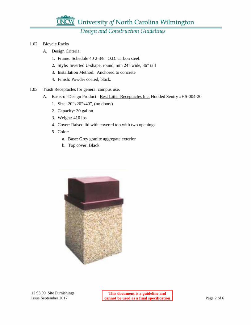
12 93 00 Site Furnishings This document is a guideline and cannot be used as a final specification
Issue September 2017 Page 2 of 6
1.02 Bicycle Racks A. Design Criteria:
1. Frame: Schedule 40 2-3/8” O.D. carbon steel. 2. Style: Inverted U-shape, round, min 24” wide, 36” tall 3. Installation Method: Anchored to concrete 4. Finish: Powder coated, black.
1.03 Trash Receptacles for general campus use. A. Basis-of-Design Product: Best Litter Receptacles Inc. Hooded Sentry #HS-004-20
1. Size: 20”x20”x40”, (no doors) 2. Capacity: 30 gallon 3. Weight: 410 lbs. 4. Cover: Raised lid with covered top with two openings. 5. Color:
a. Base: Grey granite aggregate exterior b. Top cover: Black

12 93 00 Site Furnishings This document is a guideline and cannot be used as a final specification
Issue September 2017 Page 3 of 6
1.04 Trash Receptacles for Chancellors Walk. (Reserved) A. Basis-of-Design Product:
1. Size: 2. Capacity: 3. Weight: 4. Cover: 5. Color:
1.05 Trash Receptacles for Housing A. Basis-of-Design Product: DuMor Inc, or Victor Stanley, Inc., or Equivalent.
1. Steel Facing Surrounds: Evenly patterned, parallel flat steel straps, bars, or tubular shapes. 2. Support Frames: Steel; welded: 3. Hurricane rated: 4. Steel Finish: Powder coated, color to be determined
1.06 Trash Compactor
A. Basis of Design Product: BigBelly + SmartBelly, Double Station Solar Trash Compactor,
Model # WS-BBSB-DBL-1YR with options. 1. Black Hopper with ‘Trashman” Icon 2. Blue Faceplate with ‘Bottles, Cans, Paper’ Text 3. Blank side skins for Wraps/Panels 4. 18” x 30” Messaging Panels for Side Skins with Recycle Inserts

12 93 00 Site Furnishings This document is a guideline and cannot be used as a final specification
Issue September 2017 Page 4 of 6

12 93 00 Site Furnishings This document is a guideline and cannot be used as a final specification
Issue September 2017 Page 5 of 6
1.07 Decorative Metal Bollards A. Basis of Design Product: Olympic Foundry Decorative Products Model #CB-F.
1. Item is distributed by FairWeather Site Furnishings. 2. Material: Ductile Iron 3. Finish: Polyester powder coat finish utilizing an epoxy prime coat and a polyester top
coat. a. Color: Black

12 93 00 Site Furnishings This document is a guideline and cannot be used as a final specification
Issue September 2017 Page 6 of 6
1.08 Parking Lot Removable Bollards

21 10 00 UNCW Fire Sprinkler Systems This document is a guideline and cannot be used as a final specification
Issue September 2017 Page 1 of 2
21 10 00 UNCW Standards for Fire Sprinkler System & Fire Suppression Design & Installation
Part 1: General Standards
A. Electric fire pumps only. No diesel fire pumps allowed. B. System design and installation shall comply with the most recent version of the N.C. State
Construction Office document titled “Water Based Fire Protection Systems Guidelines and Policies”, the most recently adopted version of NFPA 13, and these UNCW design & construction guidelines. Designers shall closely review all shop drawings and monitor & inspect all installations to confirm they meet these criteria and standards.
C. Plastic sprinkler pipe is not allowed. D. All system drains and inspectors test points must be fully piped to discharge outside the
building. 1. Floor drains, hoses, or buckets are not acceptable to use for discharge or drain water. 2. All water flow switches require an inspectors test valve to be installed and piped to
discharge outside the building. 3. Provide a poured concrete splash pad to prevent soil erosion at the discharge of all drain
lines and inspectors test discharge lines. 4. Inspectors test valves shall not be installed above ceilings. 5. Inspectors test valves shall be operable from standing floor level without the use of
ladders. Maximum height above finished floor to the valve handle is seven feet. E. “Tyco” brand model DPV-1 dry valves are the preferred model for use on dry sprinkler
systems. F. Any dry sprinkler valve that requires the removal of cover plates to reset the valve after
tripping is not acceptable. G. “Tyco” brand model DV-5 or “Reliable” brand type D valves are the preferred models for use
on pre-action sprinkler systems. H. Pre-action or suppression system releasing control panels shall be “Notifier” brand control
equipment. I. CO2 fire suppression agent is not allowed. Use other clean agent gasses such as “FM-200”
etc. J. “Ansul” or “Kiddie” brand suppression equipment is the preferred brands for kitchen hood
wet chemical fire suppression systems. 1. Where required, “Guardian III” brand is the preferred equipment for residential cooktop
wet chemical fire suppression systems. 2. Residential Guardian III wet chemical fire suppression systems, when installed, require
automatic release, a wall mount manual release pull station, and shunt trip equipment to disconnect all power to the cooktop during agent release.
3. Residential wet chemical fire suppression systems shall be monitored for discharge by the building fire alarm system and shall initiate general alarm.
K. “Ansul” brand is the preferred brand for suppression tanks/cylinders and firing heads for clean agent systems.

21 10 00 UNCW Fire Sprinkler Systems This document is a guideline and cannot be used as a final specification
Issue September 2017 Page 2 of 2
L. Where ever possible design elevator machine rooms without the use of dry chemical fire suppression – use wet sprinkler. 1. “Kiddie” brand suppression tanks and firing heads are the preferred brand when dry
chemical suppression systems are required in elevator machine rooms (for example when wet fire sprinkler is unavailable).
2. Where ever possible design elevators so that fire sprinklers are not required in the elevator shaft.
M. Water flow detection on wet fire sprinkler systems shall be by vane type flow switches. 1. “Potter” is the preferred brand of vane type water flow switches.
N. “Storz” type connections are the required style/design of FDC connections. O. “System Sensor” or “Potter” are the preferred brand of air pressure switches for monitoring
hi/lo air on dry/pre-action fire sprinkler systems. P. “Tyco” or “Globe” brand are the preferred brand of alarm check valves and trim.
1. Check valves 2.5 inches and larger shall have a removable faceplate cover for access to the valve interior. “Tyco”, “Viking”, and “Globe” are the preferred brands.
Q. All fire sprinkler piping and control valves shall be installed inside buildings in conditioned space. PIV valves are the only component allowed outdoors. The use of “hot boxes” for fire sprinkler control valves is not allowed. 1. Fire sprinkler control valves shall not be installed above lay-in or dry wall ceilings. 2. Fire sprinkler control valves shall be operable from standing floor without the use of
ladders. Maximum height above finished floor to the valve handle is seven feet. 3. Install isolation control valves on each floor riser so that individual floors can be serviced
without disrupting fire protection to the other floors of the building. 4. Install check valves on each floor riser.
R. Only tankless type air compressors are acceptable for use on dry sprinkler systems. 1. “General” is the preferred alternative brand of air compressors for use on dry/pre-action
sprinkler systems. S. “Kennedy” is the preferred brand of OS&Y valves 4 inches and larger in size. T. “Eaton Cutler Hammer” is the preferred brand of fire pump controllers. U. “Tyco”, “Viking”, “Reliable”, or “Globe” brand fire sprinkler heads are acceptable for use. V. “Kennedy”, “Tyco”, or “Victaulic” are the preferred brand of butterfly type control valves. W. No water driven motor alarm gongs – 24vdc electric water flow bells only.
1. Water flow bells shall be powered from and controlled by the fire alarm control panel through the use of addressable relays.
X. Install at least one piping end cap per floor at the furthest point on the run. 1. Install a valved flushing connection on at least one end cap on each floor at the furthest
point on the run in conjunction with an end cap. 2. Flushing connections must be accessible and not installed above duct work, cable trays,
conduit racks, electrical panels, sheet rock ceilings, or abutted to walls.

22 00 00 – 22 99 99 Plumbing This document is a guideline and cannot be used as a final specification
Issue September 2017 Page 1 of 8
22 00 00 General Plumbing
Part 1: Main Campus
1.01 Campus Utilities A. All utilities to a building shall be metered. All meters shall be tied into the building control
system. A bypass that can accommodate full demand shall be provided around each meter. B. Campus Energy Management Control System
1. Two tier architecture. 2. First Tier - Tridium Niagra N4 with Energy Analytics software. 3. Second Tier
a. Lon communication network with LonWorks certified controllers. b. Modbus communication network for devices that traditionally communicate Modbus
(meters, etc.) C. UNCW owns the domestic water distribution – metering tied into EMCS through the
building’s network area controller. D. UNCW owns the gas distribution – metering tied into EMCS through the building’s network
area controller. E. UNCW owns the main campus electrical distribution - metering from buildings electrical
monitoring system / switchgear / main panels tied into EMCS through the building’s network area controller.
F. All underground nonmetallic piping shall have tracer wire. G. All underground piping shall have warning tape installed above it 6” below finish grade.
1.02 Training A. Training shall be provided for the Owner’s employees for all new building equipment to
include variable frequency drives and other major equipment. Training shall be provided by the manufacturer’s representative to the satisfaction of the Owner. Training should include an explanation of the operational design theory of the system. Training should also address any variations from the original design in the construction of the system and their affect on the system operation. Training shall be both classroom (which may be provided by the Owner) and “hands on”.
B. Training should be completed one month prior to the beneficial occupancy of the building. At the completion of training, The Owner’s personnel shall be able to make
1.03 Mechanical Room Design A. Each building shall have a minimum of one mechanical room providing adequate working
clearances for all equipment. Adequate means of access shall be provided for replacement of the largest piece of equipment without removing the walls.
B. All major equipment shall be located at ground level. C. Mechanical rooms shall have a minimum of one each 120 volt electrical receptacle and one
hose bib.

22 00 00 – 22 99 99 Plumbing This document is a guideline and cannot be used as a final specification
Issue September 2017 Page 2 of 8
D. Mechanical room floor shall slope to the floor drain. Mechanical rooms shall be provided with hoist beams or adequate space to install “A” frames for the removal of equipment such as compressors, etc.
E. Overflow lines – All equipment overflow or blow down lines shall be extended to drains. F. Mechanical rooms shall be designed with adequate soundproofing. G. Mechanical rooms shall be accessible by vehicle, and shall be provided with service vehicle
parking. H. All boilers and chillers installed on UNCW facilities shall have a manufacturer’s
representative based in reasonable proximity. I. Mechanical Rooms containing chillers, water treatment equipment, hazardous materials etc.,
shall be equipped with an eyewash station supplying tepid water and meeting ANSI Z358.1
1.04 Additional Design Information Organized by Specification Section
22 05 13 Common Motor Requirements For Plumbing Equipment
1.01 Motors A. All motors shall be NEMA Premium Efficiency. B. Electric motors of 5 horsepower and larger shall have wiring terminated in the motor terminal
junction box and accomplished with either copper split bolts or ring terminal bolts and nuts. Wire nuts are not acceptable on motors of five (5) horsepower and larger.
C. All motors larger than 15hp should be equipped with a lift eye in the frame of the motor. D. Designers shall specify correct motor horsepower and frame to fit the intended application.
Do not oversize the motor. Service factor on motors to be 1.15. E. All motors except light-duty fractional horsepower motors shall be provided with motor
controllers. Controllers shall provide under voltage protection when used with momentary contact control devices, and under voltage release when used with maintained contact control devices. Motor control devices shall be contained in enclosures that are in compliance with the National Electric Code and NEMA enclosure standards for the intended application.
F. Fractional horsepower motors shall be electronically commutated variable speed.
1.02 VFDs A. Acceptable manufacturers shall be:
1. Danfloss Graham 2. Square D 3. ABB 4. Honeywell 5. Cutler Hammer
1.03 VFD ByPass A. Provide a separately housed manual 3 contactor bypass consisting of a door interlocked main
fused disconnect pad lockable in the off position, a built-in motor starter, and a four position DRIVE/OFF/LINE/TEST switch controlling three contactors. In the DRIVE position, the
22 00 00 – 22 99 99 Plumbing This document is a guideline and cannot be used as a final specification
Issue September 2017 Page 3 of 8
motor is operated at an adjustable speed from the drive. In the OFF position, the motor and the drive are disconnected. In the LINE position, the motor is operated at full speed from the AC line power and the power is disconnected from the drive, so that service can be performed. In the TEST position, the motor is operated at full speed from the AC line power. This allows the drive to be given an operational test while continuing to run the motor at full speed in bypass. Customer supplied normally closed dry contact shall be interlocked with the drive’s safety trip circuitry to stop the motor whether in DRIVE or BYPASS mode in case of an external safety fault. The use of microprocessor based bypass control shall not be allowed.

22 00 00 – 22 99 99 Plumbing This document is a guideline and cannot be used as a final specification
Issue September 2017 Page 4 of 8
22 05 19 Meters and Gages for Plumbing Equipment
1.01 Water Meters (Controls Contractor Supplied) A. Water meters shall be provided by the Controls Contractor and must be included in the
Controls specifications. B. Water meters are to be located inside the mechanical room. C. Acceptable meter manufacturers and associated registers:
1. Appropriate Neptune Meter with Neptune: E-Coder register w/ the potted cable (The R900i register is NOT compatible, since it does not feature a connection wire).
D. Controls Gateway: Meters not having direct Modbus communication shall be integrated to the Building Management System (BMS) through a Modbus gateway such as a Scadametrics Ethermeter http://www.scadametrics.com/ The gateway device shall directly interrogate the meter register and shall calculate and relay the following parameters to the BMS: 1. Totalized Volume. 2. Instantaneous Flowrate
E. Building Water Meters 1. Mechanical Water meters 1.5 inches and below shall be positive displacement type 2. Mechanical Water meters above 2 inches and above shall be compound type meter with
matching strainer. F. Irrigation Water Meters
1. Meters shall be minimum 2” turbine meter with matching strainer 2. For new buildings and retrofits, we will install the backflow preventers and meters
(including irrigation) inside the building. This will eliminate the need for hotboxes and keep as much controls wiring inside the building as possible.
1.02 Gas Meters (Controls Contractor Supplied) A. Gas Meters shall be Onicon inline insertion meter with D-100 Display. Display shall connect
to BMS via Lon B. Controls Gateway: Meters not having direct Modbus communication shall be integrated to
the Building Management System (BMS) through a Modbus gateway such as a Scadametrics Ethermeter http://www.scadametrics.com/ The gateway device shall directly interrogate the meter register and shall calculate and relay the following parameters to the BMS: 1. Totalized Volume. 2. Instantaneous Flowrate

22 00 00 – 22 99 99 Plumbing This document is a guideline and cannot be used as a final specification
Issue September 2017 Page 5 of 8
22 05 53 Identification for Plumbing Piping and Equipment
1.01 Symbols A. Mechanical and electrical drawing symbols shall be in accordance with guidelines of the
American National Standards Institute (ANSI). The Designer shall uniquely number all motor driven equipment on the drawings (e.g. for unit heaters, use P-1, P-2, etc. even though both of these units are the same size and type).
1.02 Color Standard A. Following is the color standard for mechanical piping identification:
1. Potable Hot and Cold Water and Domestic Hot Water Recirculation - Green 2. Non-Potable / Make-Up Water / Grey Water - Purple (Non-Potable / Make-Up Water /
Grey Water must be color coded everywhere in the project) 3. Fire Protection – Red 4. Natural Gas – Yellow
1.03 Identification Requirements A. Labeling shall be stenciled onto piping. B. Labeling shall include directional arrows. C. The Contractor shall use stencils to identify all such equipment using the numbering system
shown on the drawings. Use oil based enamel paint with a color that contrasts with the equipment finish. In finished areas, identification shall be located on the inside surfaces of access doors. In unfinished areas, identify on outside surfaces. Tags may be used in areas where preferred, but only by using as more permanent method of attachment than glue or wire.
D. The Electrical Contractor shall identify disconnect devices and starters. Identification shall be affixed to panel surfaces or to the inside covers when surface mounting is objectionable.
E. Valve numbers shall be engraved or stamped onto metal plates (1” x 2”) or metal discs (1 ¼”) in diameter attached to the valves by 10-gauge brass “S” hooks. Provide a numbering system identifying all valves regardless of valve size or service.
F. Location of all above ceiling equipment is to be marked on the suspended ceiling grid in an unobtrusive manner with engraved phenolic markers.

22 00 00 – 22 99 99 Plumbing This document is a guideline and cannot be used as a final specification
Issue September 2017 Page 6 of 8
22 11 16 Domestic Water Piping
1.01 Materials and Accessories A. All domestic water piping inside the building shall be copper. B. All underground PVC piping regardless of use shall have tracer wire. C. Hose bibs will be provided on each side of all buildings. Hose bibs will have detachable
handles or equivalent means to be inaccessible to the general public. They will be equipped with anti-siphon devices.
D. All backflow preventers should be easily accessible for inspection, maintenance and repair. E. Outdoor Natural Gas and Potable water valves shall be enclosed in a concrete manhole with a
traffic rated lid. The lid shall be 2 inches above finish grade. All valves shall be equipped with accessible grease fittings.

22 00 00 – 22 99 99 Plumbing This document is a guideline and cannot be used as a final specification
Issue September 2017 Page 7 of 8
22 11 23 Domestic Water Pumps
1.01 Motors A. Circulation pumps shall have variable speed Electronically Commutated Motor (ECM). B. Pump speeds shall not exceed 1760 rpm.
22 13 16 Sanitary Waste and Vent Piping
1.01 Materials A. All Sanitary and vent piping shall be cast iron.
22 13 19 Sanitary Waste Piping Specialties
1.01 Floor Drains A. All floor drains shall be of the type which permits removal of the cover only with a “special
tool” or by qualified people.
22 14 13 Facility Storm Drainage Piping
1.01 Materials A. All underground PVC piping regardless of use shall have tracer wire.

22 00 00 – 22 99 99 Plumbing This document is a guideline and cannot be used as a final specification
Issue September 2017 Page 8 of 8
22 42 00 Commercial Plumbing Fixtures
1.02 Water Closets A. Water conservation will be considered in the selection of fixtures. B. All fixtures in restrooms shall be of the wall hung variety, not floor mounted. C. Use of automatic flush valves will be considered in design of toilet fixtures.
1.03 Urinals A. Water conservation will be considered in the selection of fixtures. B. All fixtures in restrooms shall be of the wall hung variety, not floor mounted. C. Use of automatic flush valves will be considered in design of toilet fixtures.
1.04 Lavatories A. Water conservation will be considered in the selection of fixtures. B. All fixtures in restrooms shall be of the wall hung variety.
1.05 Sinks A. Water conservation will be considered in the selection of fixtures. B. All fixtures in restrooms shall be of the wall hung variety. C. Janitor’s Mop sinks shall utilize a Chicago 952-1/2CP fixture for the DHW and DCW. Use of
a single fixture connected to both hot water and cold water is prohibited.
1.06 Showers, Receptors, Basins A. Water conservation will be considered in the selection of fixtures.
1.07 Wash Fountains A. Water conservation will be considered in the selection of fixtures.
1.08 Medical Plumbing Fixtures A. Water conservation will be considered in the selection of fixtures.
1.09 Emergency Plumbing Fixtures A. Mechanical Rooms containing chillers, water treatment equipment, hazardous materials etc.,
shall be equipped with an eyewash station supplying tepid water and meeting ANSI Z358.1.
1.10 Drinking Fountains and Pressure Water Coolers A. In addition to drinking fountains, water bottle filling stations shall be integrated into the
building design.

23 00 00 – 23 99 99 Mechanical This document is a guideline and cannot be used as a final specification
Issue September 2017 Page 1 of 12
23 00 00 General Mechanical
Part 1: Main Campus
1.01 Campus Utilities A. UNCW is in the process of centralizing chilled water and heating hot water production in
specific portions of the campus. B. Buildings connecting to a centralized hydronic system shall have a controllable bridged
building loop with its own building pumps. See UNCW chilled water bridge schematic. C. All utilities to a building shall be metered. All meters shall be tied into the building control
system. D. Campus Energy Management Control System
1. Two tier architecture. 2. First Tier - Tridium Niagra N4 with Energy Analytics software. 3. Second Tier - Lon network with LonWorks certified controllers. 4. See control system schematic.
E. UNCW owns the domestic water distribution – metering tied into EMCS through the building’s network area controller.
F. UNCW owns the gas distribution – metering tied into EMCS through the building’s network area controller.
G. UNCW owns the main campus electrical distribution - metering from buildings electrical monitoring system / switchgear / main panels tied into EMCS through the building’s network area controller.
H. All underground nonmetallic piping shall have tracer wire. I. All underground piping shall have warning tape installed above it 6” below finish grade.
1.02 Building HVAC A. UNC-Wilmington's standard HVAC system is the fully ducted, centralized, variable volume,
air handling unit serving VAV terminal units with hot water reheat coils. Centralized air handling units shall have airside enthalpy economizer capability. CO2 monitors shall be utilized to control outside air requirements. Building system shall actively monitor and control humidity as well as temperature. Building system shall actively monitor and control building pressurization. Total heat recovery shall be utilized. The system shall be fully ducted and insulated on both the supply and return side. Ductwork shall be externally insulated metal ductwork. Duct liner is prohibited. Exposed insulation anywhere in the system is prohibited. The use of non-centralized fan powered devices such as fan powered terminal units and fan coil units is typically prohibited and allowed only by permission of the University under certain circumstances. Assembly spaces such as classrooms and conference rooms shall utilize CO2 or occupancy sensing to put the room into a “standby” mode when the room is scheduled as occupied. Office space shall utilize occupancy sensing.
B. Air handling units shall be double wall construction with no exposed insulating liner. C. Air handling unit fan sections shall utilize direct drive “fan arrays” of multiple low
horsepower fans. Where possible utilize permanent magnet motors.

23 00 00 – 23 99 99 Mechanical This document is a guideline and cannot be used as a final specification
Issue September 2017 Page 2 of 12
D. Air handling unit dampers shall be TAMCO Series 9000 with the options of thermally broken louvers and frames and salt water resistance.
E. Air Handling Unit Mixing boxes shall be constructed that they completely mix outside air with return air to prevent freezestat trips. Dampers shall be parallel blade design and arranged such that the return air and outside air are directed at each other to aid in mixing. Static diverter blades shall be used to force air mixing.
F. All air handling units shall be set in a metal, water tight auxiliary drain pan. The pan shall be piped to a floor drain. Float switches will not be used. All air handling units shall have sufficient clearance of all four sides for maintenance. All floor mounted air handling units shall have a safe walkway on all four sides.
G. Air handling units shall have a grounded, electrical 120 volt AC outlet within 6 feet of the unit, and a fresh water hose bib with anti-siphon device nearby for coil cleaning. In the case of adjacent air handlers outlet and hose bib shall be adequate for all units. All air handling units shall have an on/off switch at the unit that breaks control voltage to the starter motor. All air handling unit rooms shall have doors appropriately sized for equipment change outs.
H. Fans units shall be provided with appropriate isolation pads or vibration isolators to suppress transmission of equipment vibration.
I. Due to the negative pressures inherent in draw through units, all draw through type units shall be equipped with Costgard condensate control devices (as available from Trent Technologies).
J. If return air fans are used on the air handling units, they shall be located within the air handler itself and be supplied with access doors to the motor and fan shaft.
K. The University encourages innovative design, but requires such design to meet the approval of the University.
L. Building HVAC systems must be able to operate under the established requirements of the centralized chilled water, and heating hot water systems.
M. Building stairwells shall be conditioned. N. Mechanical Rooms will be conditioned. O. Location of all above ceiling equipment is to be marked on the suspended ceiling grid in an
unobtrusive manner, e.g. engraved phenolic markers. P. Designer will ensure that outside operating equipment is below noise levels allowed by local
ordinances. Q. Rooms requiring 24 hour conditioning, such as electrical rooms and telecom rooms, shall be
evaluated for its own conditioning system. This will allow the central air handling units to be turned down during unoccupied periods. Systems such as variable refrigerant flow systems have been used in the past.
1.03 Training A. Training shall be provided for the Owner’s employees for all new building equipment to
include chillers, boilers, control systems, fume hoods, variable frequency drives and other major equipment. Training shall be provided by the manufacturer’s representative to the satisfaction of the Owner. Training should include an explanation of the operational design theory of the system. Training should also address any variations from the original design in the construction of the system and their effect on the system operation. Training shall be both classroom (which may be provided by the Owner) and “hands on”.

23 00 00 – 23 99 99 Mechanical This document is a guideline and cannot be used as a final specification
Issue September 2017 Page 3 of 12
B. Training should be completed one month prior to the beneficial occupancy of the building. At the completion of training, the Owner’s personnel shall be able to operate all systems as designed.
1.04 Mechanical Room Design A. Each building shall have a minimum of one mechanical room providing adequate working
clearances for all equipment. Adequate means of access shall be provided for replacement of the largest piece of equipment without removing the walls.
B. Mechanical rooms should be tempered (heated, cooled, and dehumidified) to improve equipment operating environment.
C. All major equipment shall be located at ground level. D. Mechanical rooms shall have a minimum of one each 120 volt electrical receptacle and one
hose bib. E. Mechanical room floor shall slope to the floor drain. Mechanical rooms shall be provided
with hoist beams or adequate space to install “A” frames for the removal of equipment such as compressors, etc.
F. Overflow lines – All equipment overflow or blow down lines shall be extended to drains. G. Mechanical rooms shall be designed with adequate soundproofing. H. Mechanical rooms shall be accessible by vehicle, and shall be provided with service vehicle
parking. I. Rooftop mounted equipment will be kept to an absolute minimum. J. All chiller rooms shall be equipped with a welding machine electrical outlet. K. All boilers and chillers installed on UNCW facilities shall have a manufacturer’s
representative based in reasonable proximity. L. Mechanical Rooms containing chillers, water treatment equipment, hazardous materials etc.,
shall be equipped with an eyewash station supplying tepid water and meeting ANSI Z358.1
1.05 Additional Design Information Organized by Specification Section
23 05 13 Common Motor Requirements for Mechanical Equipment
1.01 Motors A. All motors shall be NEMA Premium Efficiency, or where possible, permanent magnet ECM. B. Electric motors of 5 horsepower and larger shall have wiring terminated in the motor terminal
junction box and accomplished with either copper split bolts or ring terminal bolts and nuts. Wire nuts are not acceptable on motors of five (5) horsepower and larger.
C. All motors larger than 15hp should be equipped with a lift eye in the frame of the motor. D. Designers shall specify correct motor horsepower and frame to fit the intended application.
Do not oversize the motor. Service factor on motors to be 1.15. E. All motors except light-duty fractional horsepower motors shall be provided with motor
controllers. Controllers shall provide under voltage protection when used with momentary contact control devices, and under voltage release when used with maintained contact control devices. Motor control devices shall be contained in enclosures that are in compliance with the National Electric Code and NEMA enclosure standards for the intended application.
23 00 00 – 23 99 99 Mechanical This document is a guideline and cannot be used as a final specification
Issue September 2017 Page 4 of 12
F. Fractional horsepower motors shall be fully variable speed electronically commutated motors.
1.02 VFDs A. Acceptable manufacturers shall be:
1. Honeywell 2. Danfloss Graham 3. Square D 4. ABB 5. Cutler Hammer
1.03 VFD ByPass A. Provide a separately housed manual 3 contactor bypass consisting of a door interlocked main
fused disconnect pad lockable in the off position, a built-in motor starter, and a four position DRIVE/OFF/LINE/TEST switch controlling three contactors. In the DRIVE position, the motor is operated at an adjustable speed from the drive. In the OFF position, the motor and the drive are disconnected. In the LINE position, the motor is operated at full speed from the AC line power and the power is disconnected from the drive, so that service can be performed. In the TEST position, the motor is operated at full speed from the AC line power. This allows the drive to be given an operational test while continuing to run the motor at full speed in bypass. Customer supplied normally closed dry contact shall be interlocked with the drive’s safety trip circuitry to stop the motor whether in DRIVE or BYPASS mode in case of an external safety fault. The use of microprocessor based bypass control shall not be allowed.
23 05 16 Expansion Fittings and Loops for HVAC Piping
1.01 Expansion Guidelines A. Mechanical expansion devices are not allowed. Pipe loops shall be used.
23 05 19 Meters and Gages for HVAC Piping
1.01 General A. All meters shall be tied to the local area controller. Instantaneous and where required,
totalized flow shall be relayed to the BMS.
23 05 23 General Duty Valves for HVAC Piping
1.01 Gas Valves A. Outdoor Natural Gas valves shall be enclosed in a concrete manhole with a traffic rated lid.
The lid shall be 2 inches above finish grade. All valves shall be equipped with accessible grease fittings.

23 00 00 – 23 99 99 Mechanical This document is a guideline and cannot be used as a final specification
Issue September 2017 Page 5 of 12
23 05 53 Identification for HVAC Piping and Equipment
1.01 Symbols A. Mechanical and electrical drawing symbols shall be in accordance with guidelines of the
American National Standards Institute (ANSI). The Designer shall uniquely number all motor driven equipment on the drawings (e.g. for unit heaters, use UH-1, UH-2, etc. even though both of these units are the same size and type).
1.02 Color Standard A. Following is the color standard for mechanical piping identification:
1. Chilled Water Supply and Return - Dark Blue 2. Condenser / Tower Water Supply and Return - Light Blue 3. Heating Hot Water Supply and Return – Orange 4. Natural Gas – Yellow
1.03 Identification Requirements A. Labeling shall be stenciled onto piping. B. Labeling shall include directional arrows. C. The Contractor shall use stencils to identify all such equipment using the numbering system
shown on the drawings. Use oil based enamel paint with a color that contrasts with the equipment finish. In finished areas, identification shall be located on the inside surfaces of access doors. In unfinished areas, identify on outside surfaces. Tags may be used in areas where preferred, but only by using as more permanent method of attachment than glue or wire.
D. The Electrical Contractor shall identify disconnect devices and starters. Identification shall be affixed to panel surfaces or to the inside covers when surface mounting is objectionable.
E. Valve numbers shall be engraved or stamped onto metal plates (1” x 2”) or metal discs (1 ¼”) in diameter attached to the valves by 10-gauge brass “S” hooks. Provide a numbering system identifying all valves regardless of valve size or service.
F. Location of all above ceiling equipment is to be marked on the suspended ceiling grid in an unobtrusive manner, e.g. small color-coded dots.
23 05 93 Testing, Adjusting and Balancing for Hvac
1.01 General A. Per project requirements.
23 07 16 HVAC Equipment Insulation
1.01 Air Handlers A. Units shall be double walled with no insulation exposed to system air.

23 00 00 – 23 99 99 Mechanical This document is a guideline and cannot be used as a final specification
Issue September 2017 Page 6 of 12
23 07 19 HVAC Piping Insulation
1.01 Hydronic piping A. Insulation to be performed fiberglass. Indoor covers to be color coded PVC jacket and
outdoor covers to be aluminum.
23 09 00 Instrumentation and Control For HVAC
1.01 General A. Use UNCW Controls Specification. B. All outside thermostat bulbs shall be sleeved with no less than 1 ½ inch schedule 40 PVC
pipe through outer building walls to facilitate replacement. C. Instead of glass thermometers, specify Solar Self-indicating Temperature Transmitter such as
the Weiss DVUT. D. Campus energy management control system: Two tier architecture
1. First Tier - Tridium Niagra N4 with Analytics software. 2. Second Tier - Lon network with LonWorks certified controllers.
E. See control system schematic.
1.02 Control Valves A. Preferred Control Valves for hydronic systems shall be pressure independent modulating 2-
way controls valves. These valves replace the standard control valves and automatic flow limiting devices. Where pressure independent control valves cannot be utilized, A “characterized control valve” aka CCV ball valve shall be used in conjunction with a circuit setter.
B. Acceptable manufacturers of pressure independent modulating 2-way controls valves are: 1. Flow Control Industries Inc model Delta P Valve. (Preferred valve) 2. Belimo model PICCV 3. Honeywell VRN 4. Griswold Controls model MVP 5. Nelson Controls LLC model GP Series
1.03 Sensors A. All VAV units will have temperature sensors downstream of the heating coil.
1.04 VFDs A. Acceptable manufacturers shall be:
1. Honeywell 2. Danfloss Graham 3. Square D

23 00 00 – 23 99 99 Mechanical This document is a guideline and cannot be used as a final specification
Issue September 2017 Page 7 of 12
4. ABB 5. Cutler Hammer
1.05 Dampers A. All dampers shall be TAMCO Series 9000 SW and thermally broken.
23 09 93 Sequence of Operation for HVAC Controls
1.01 General A. Sequence of Operations for all systems and equipment must be put on document drawings.
23 11 23 Facility Natural-Gas Piping
1.01 General A. All boiler gas trains shall be OSHA and FM compliant. B. Flue outlets and gas vents must be shown on drawings and located to avoid any noise, odor,
or re-entrainment issues. C. All natural gas piping for boilers shall have gauges located on the supply gas line before and
after the gas regulator and before entering the burner. D. All boiler gas piping shall have ¼ inch test ports before and after the regulator and at the
burner.
23 21 13 Hydronic Piping
1.01 General A. Thermally fused PP-R or PP-RCT is the standard piping for building heating and cooling.
Acceptable Manufacturers are Aquatherm blue pipe, ISCO PP-RCT or approved equal. Chilled water piping may allow for HDPE piping with approval.
B. All underground non-metallic piping regardless of use shall have tracer wire. C. Air and dirt separation is required on all hydronic systems. Separators shall be the Spirovent
Dirt, the Taco series 4900-AD, the Caleffi DISCALDIRT series, or the Minikin EMFLEX Model SMAD. These separators remove air through coalescence and dirt through medium impingement. These single units replace a separate air separator and dirt removal system
23 21 23 Hydronic Pumps
1.01 General A. All pumps shall be inline split coupled pumps. All pumps (condenser, chill water, hot water,
primary, secondary, or loop pumps) shall have adequate clearances to service them. All pumps shall have a shut off valve on both the suction and discharge lines within three feet of the pump. All pumps shall have thermometers mounted in a dry well on the suction and

23 00 00 – 23 99 99 Mechanical This document is a guideline and cannot be used as a final specification
Issue September 2017 Page 8 of 12
discharge lines within three feet of the pump. All electrical disconnects for the pumps shall be clearly marked as to the pump, which they service. All pumps will be clearly marked as to their function, e.g. chill water, hot water, etc. All piping to pumps shall be clearly marked as to the direction of flow and function. All variable frequency drives that control pumps shall be clearly marked as to the pumps they control, and be equipped with a manual bypass for use in the event of their failure. All primary loop and secondary loop piping shall be clearly marked as such. Each pump shall have a common pressure gauge valved to measure suction and discharge pressures.
B. Maximum pump speeds shall not exceed 1760 rpm.
23 23 00 Refrigerant Piping
1.01 Refrigerant Monitoring A. All chillers shall be provided with a refrigerant reclaim machine capable of reclaiming the
type and amount of refrigerant contained in the respective chiller.
23 25 00 HVAC Water Treatment
1.01 General A. Unless connected to a centralized system, all new buildings shall include chemical treatment
programs for applicable equipment (boilers, cooling towers, chill water loops) for a period of one year. Said program to include all required chemicals necessary to maintain proper chemical levels to prevent corrosion and mildew, and instruction for operating personnel. Chemical for these programs will be provided in five gallon containers, premixed. Dry powders are not acceptable. The chemical company will ensure that the equipment supplied for the program is installed in a neat and professional manner.
B. The chemical company representative shall make a visit every two weeks to the UNCW and check in with the UNCW HVAC supervisor (or his/her representative). At the time of the visit water samples will be taken the representative will coordinate with the UNCW representative to ensure that the equipment is being properly utilized.
23 31 13 Metal Ducts
1.01 General A. No insulation will be used inside ducts. B. Seal all duct, with the exception of transfer ducts, in accordance with SMACNA seal class
"A"; all seams, joints, and penetrations shall be sealed. C. Metal ducts shall be used in all areas. Flexible ducts used to connect to diffusers shall not
exceed 8’ in length.

23 00 00 – 23 99 99 Mechanical This document is a guideline and cannot be used as a final specification
Issue September 2017 Page 9 of 12
23 31 19 HVAC Casings
1.01 General A. To be double walled with no exposed internal insulation.
23 36 00 Air Terminal Units
1.01 General A. Fan Powered boxes are not permitted. B. All VAV boxes shall have two access doors, one on each side of the heat coil for coil
cleaning. C. All VAV units located above the ceiling shall have their location marked on the ceiling grid
directly below the unit. D. Variable air volume boxes shall be of double wall construction. E. All VAV units will have temperature sensors downstream of the heating coil.
23 37 13 Diffusers, Registers and Grilles
1.01 General A. Perforated supply air diffusers are not acceptable. Standard supply air diffuser is square cone
type. B. Per project requirements.
23 41 33 High-Efficiency Particulate Filtration
1.01 General A. Differential pressure sensors and gauges are required before and after each set of filters. B. 2 inch prefilter, 6 inch box filter on small unitary AHUs. C. 2 inch prefilter, 24 inch box filter on larger building AHUs
23 52 16 Condensing Boilers
1.01 General A. For 2,000 MBH boilers and above, the preferred set of three boilers for the base bid are:
1. Fulton Endura, Endura+, or Vantage 2. Aerco; Benchmark (BMK-2 or BMK-3) 3. Viessman; Vitocrossal / Vertomat
B. For 2,000 MBH boilers, the University has add/alternate for Fulton condensing boilers model Benchmark 2.0 (BMK-2.).

23 00 00 – 23 99 99 Mechanical This document is a guideline and cannot be used as a final specification
Issue September 2017 Page 10 of 12
C. For 1,000 MBH boilers, the University has an add alternate for Fulton Endura. D. For less than 1,000 MBH boilers, the University has an add alternate for Fulton Endura. E. Boilers shall be provided with factory sound attenuators on intake and exhaust. F. Multiple boiler installations shall be provided with manufacturers’ Boiler Manager. Boiler
Manager shall communicate with Building Management System (BMS) via Modbus.
23 63 13 Air-Cooled Condensers
1.01 General A. The refrigerant coils/fins of all air cooled equipment shall be supplied with a salt water
resistant coating applied at the factory.
23 64 16 Centrifugal Water Chillers
1.01 General A. All chillers shall be supplied with a five year warranty extended warranty covering all parts
and labor. B. There shall be an add alternate for a chiller with Turbocor compressors.
23 64 19 Reciprocating Water Chillers
1.01 General A. All chillers shall be supplied with a five year warranty extended warranty covering all parts
and labor.
23 65 00 Cooling Towers
1.01 Preferred Vendor A. University preferred cooling tower is the Tower Tech : www.towertechinc.com
23 73 13 Modular Indoor Central-Station Air Handling Units
1.01 General A. Units shall be double wall construction with no exposed insulation. B. Cooling Coil Section inner wall shall be stainless steel. C. Central air handling units shall have airside enthalpy economizer capability.

23 00 00 – 23 99 99 Mechanical This document is a guideline and cannot be used as a final specification
Issue September 2017 Page 11 of 12
D. Fans shall have appropriate isolation pads or vibration isolators to suppress vibration transmission.
E. Draw through units shall be equipped with Costgard condensate control devices. F. If return fans are required, they shall be internal to the AHU and shall have access doors for
shafts and bearings. G. All air handling units shall be set in a metal pan with a drain to the floor drain. Float switches
shall not be permitted. H. Fan Wall Systems – Systems shall consist of direct drive fans, minimum four (4) fans.
Preferred manufacturer/system: 1. Climate Craft; Fan Matrix 2. CES Group; FanWall System 3. Trane; Fan Array
I. All dampers shall be TAMCO Series 9000 SW. J. Utilize campus loop chilled water and hot water when possible. K. Utilize Trent Technologies condensate drain instead of liquid traps.
23 74 33 Dedicated Outdoor-Air Units
1.01 General A. Construction to be the same as in section 237313. B. Utilize campus loop chilled water and hot water when possible. C. Utilize Trent Technologies condensate drain instead of liquid traps
23 81 26 Split System Air-Conditioners
1.01 General A. Condensers for heat pumps and DX units shall be mounted on a level and stable concrete pad
and in areas accessible to traffic protected by bollards. B. Condensers shall be equipped with a liquid line filter dryer. C. Lines shall be run in a neat and orderly manner with no contact between lines. All refrigerant
lines shall be strapped to a section of Unistrut that is anchored to the concrete pad. D. The refrigerant coils/fins of all air cooled equipment shall be supplied with a salt water
resistant coating applied at the factory. E. Utilize Trent Technologies condensate drain instead of liquid traps.

23 00 00 – 23 99 99 Mechanical This document is a guideline and cannot be used as a final specification
Issue September 2017 Page 12 of 12
23 82 16 Air Coils
1.01 General A. All cooling/heating coils especially in duct work are to have access doors. B. Cooling coil casing, bracketing, and drain pans shall be stainless steel. C. Maximum cooling coil face velocity shall be 400 feet per minute. D. Chilled water cooling coils shall have minimum tube velocity of 4 feet per second at the
maximum flow rate.
23 82 19 Fan Coil Units
1.01 General A. The installation of fan coil units is typically prohibited and allowed only by permission of the
University under certain circumstances.
23 82 23 Unit Ventilators
1.01 General A. Rooftop equipment such as powered ventilation units shall be accessible via a roof hatch
from the floor below. B. When powered ventilators are thermostatically controlled, the thermostat control shall be at a
level that is accessible without the use of a ladder. C. Powered ventilators shall have an on/off switch at the roof vent.
23 82 39 Unit Heaters
1.01 Cabinet Type A. The installation of cabinet unit heaters is typically prohibited and allowed only by permission
of the University under certain circumstances (for example stairwell conditioning).

26 00 00 – 26 90 00 Electrical This document is a guideline and cannot be used as a final specification
Issue September 2017 Page 1 of 12
26 01 00 Electrical General
1.01 State of North Carolina-, Dept. of Administration, State Construction Office-” Electrical Guidelines and Policies” is to be used in conjunction with these UNCW Guidelines.
1.02 All electrical conductors shall be copper.
1.03 Meters shall be provided to indicate building electrical demand, see Section 26 24 16 for details
1.04 A copy of the electrical riser diagram shall be mounted near the main switchgear in the electrical room under clear protective material.
1.05 For any electric / electronic equipment proposed to be mounted on the exterior of a building, drawings showing details of such equipment shall be submitted to the University for review and approval prior to installation.

26 00 00 – 26 90 00 Electrical This document is a guideline and cannot be used as a final specification
Issue September 2017 Page 2 of 12
26 05 33 Conduit
1.01 All electrical distribution within buildings shall be installed in rigid, intermediate or EMT conduit utilizing all steel compression type fittings as connectors or couplings.
1.02 Underground raceways shall be either galvanized rigid steel or PVC duct encased in concrete; however, all ducts leaving a building shall be galvanized rigid steel for a minimum distance of five (5) feet from the building.
1.03 Red dye shall be applied to the top of freshly placed concrete in all underground high voltage (> 5KV) duct banks as a warning of electrical hazard in the event of future excavation. This is in addition to the required warning tape installed 6” below grade.
1.04 Ducts should be securely anchored during concrete placement to prevent movement. The required spacing between adjacent ducts shall be maintained with plastic spacers.
1.05 Joints in duct in a duct bank should always be staggered a minimum of 6”.
1.06 Conduit and fittings shall be concealed wherever possible especially in finished spaces and public areas. Conduit can be installed exposed in rooms like mechanical, storage etc. however they must be installed in a manner as to be protected from physical damage. Run exposed conduits neatly and as inconspicuously as practicable and install parallel or perpendicular to walls, structural members or intersections of vertical planes and ceilings. Right angle turns may be made with manufactured elbows for sizes of conduit 1-1/4 inches and larger.
1.07 Minimum size conduit for fire alarm system is ¾”

26 00 00 – 26 90 00 Electrical This document is a guideline and cannot be used as a final specification
Issue September 2017 Page 3 of 12
26 08 00 Electrical Testing
1.01 Testing on 600 volt rated equipment and cable to be done using a 1000-volt meggar. All new wire shall hold at least 100 meg ohms.
1.02 Medium voltage cable testing shall follow the manufacturer recommendations for new or installed cable, however the minimum test voltage shall be for new cable 5 times cable rating and for existing cable 3 times cable rating. Voltage in testing to increase in a 5000 volt increment and be held for 1 minutes at each voltage and for 10 minutes at the top voltage. Take and record readings at each stage as required. Caution must be used in dissipating the capacitive charge on the cable. Apply all grounds with caution and safety in mind.

26 00 00 – 26 90 00 Electrical This document is a guideline and cannot be used as a final specification
Issue September 2017 Page 4 of 12
26 12 19 Pad Mounted Distribution Transformers
1.01 All molded elbow connectors installed on high voltage cables at switches and transformers shall be equipped with high voltage test points on the elbow connectors.

26 00 00 – 26 90 00 Electrical This document is a guideline and cannot be used as a final specification
Issue September 2017 Page 5 of 12
26 18 00 Air Interrupter Switch
1.01 UNCW primary electrical system operates at a voltage of 12.47KV, wye connected. System is an underground radial feed to outdoor pad mounted transformers protected by a fused, pad mounted outdoor distribution switch centers. The distribution switch is an S&C Electric “Vista Underground Distribution “type and shall be bid as a preferred alternate when needed.

26 00 00 – 26 90 00 Electrical This document is a guideline and cannot be used as a final specification
Issue September 2017 Page 6 of 12
26 22 00 Dry Type Transformers
1.01 K-rated transformers should be used for non-linear loads. Transformers shall be Class- 80 degree rise and copper.

26 00 00 – 26 90 00 Electrical This document is a guideline and cannot be used as a final specification
Issue September 2017 Page 7 of 12
26 24 16 Panelboards
1.01 Panels A. All electrical panels are to be “industrial” / “commercial” grade. Specify the following
manufacturers only in base bid: Square “D”, General Electric, Eaton-Cutler Hammer.
1.02 Metering A. A building meter shall be provided to monitor the electrical usage of the building. B. Main distribution panel shall be equipped with digital metering to measure:
1. Voltage – phase to phase and phase to neutral 2. Amperage- all three phases 3. KW, KVAR 4. KW Demand 5. Peak Demand 6. Power factor 7. Events Recording (minimum of 7 events) 8. Meter shall be connected to the building automation system for monitoring purposes
1.03 Phase Protection A. Provide electrical phase protection at main to prevent single phasing of service to the
building.
26 00 00 – 26 90 00 Electrical This document is a guideline and cannot be used as a final specification
Issue September 2017 Page 8 of 12
26 27 26 Wiring Devices
1.01 Receptacles A. Duplex electrical receptacles, 120-volt AC shall be provided in corridors at 25-foot intervals
for housekeeping use, also in stairwells and immediately adjacent to elevators. Provide receptacles near building entrances and around the exterior of the building for maintenance use.
B. Receptacles are to be installed in the vertical position with the ground terminal on top. C. Duplex electrical outlets should be provided in classrooms for lectern, ceiling mounted
projection equipment, slide projectors, and accessible to student seating. D. All chiller rooms shall be equipped with a welding machine electrical outlet. E. Red outlets will be installed for all generator powered devices

26 00 00 – 26 90 00 Electrical This document is a guideline and cannot be used as a final specification
Issue September 2017 Page 9 of 12
26 29 23 Variable Frequency Controllers
1.01 Acceptable Manufacturers A. Danfloss Graham B. Square D C. ABB D. Honeywell E. Cutler Hammer
1.02 Requirements A. When VFD not supplied with mechanical equipment, it shall be supplied by the controls
vendor.

26 00 00 – 26 90 00 Electrical This document is a guideline and cannot be used as a final specification
Issue September 2017 Page 10 of 12
26 32 13 Packaged Engine Generators Systems
1.01 Emergency generators shall be equipped with automatic transfer switches. Specify emergency generators as manufactured only by Caterpillar and shall be bid as a preferred alternate.
1.02 Where required by critical system, uninterrupted power supplies will be provided to appropriate portions of buildings.
1.03 Buildings without emergency generator backup should have the main switchboard incorporate a design with a double throw scheme that can allow for the connection of a portable emergency generator. Interlocking on this installation must be considered to prevent accidents.
1.04 Fuel tank for emergency generator shall be installed above ground and have double wall construction to provide secondary containment. Fuel tank to be sized to provide fuel for eight (8) hours of running at 100% load plus four (4) days running at 50% load.

26 00 00 – 26 90 00 Electrical This document is a guideline and cannot be used as a final specification
Issue September 2017 Page 11 of 12
26 51 00 Interior Luminaires (Includes Emergency Lighting)
1.01 Interior lighting fixtures shall be of the energy saving type.
1.02 Fluorescent lights fixtures shall be equipped with electronic instant start ballasts. The University Standard is hinged parabolic, specular silver louvers. Consideration shall be given to indirect/direct fixtures for each project based on application. Designer shall obtain prior approval from the University to utilize indirect/direct fixtures.
1.03 Lamps to be energy saving watt saver type, insert LED spec here
1.04 Emergency lighting shall be mounted above an average person’s reach (7 ft. min.)
1.05 Wall mounted lighting fixtures are preferred in stairwells rather than high ceiling mounted units for ease of cleaning and maintenance.
1.06 Interior and exterior light fixtures mounted at high elevations shall be required to have a means of access provided for maintenance equipment that includes exterior road access and adequate pavement/floor capacity to support equipment without damage.
1.07 Strong consideration shall be given to using emergency lighting inverters rather than individual battery packs on major renovations or new building projects. The use of battery packs will require specific approval from UNCW.

26 00 00 – 26 90 00 Electrical This document is a guideline and cannot be used as a final specification
Issue September 2017 Page 12 of 12
26 56 00 Site and Exterior Lighting
1.01 All exterior lighting shall be insert LED spec here light poles shall have ground rods in each base and PVC conduit shall be installed between light poles without interruption in the conduit runs. Each base shall contain one spare conduit for future use embedded in the base. All outside lighting shall be installed with photocell control and “H-O-A” override switches at the lighting contactor. See Section 26 00 00 Appendix for exterior lighting details.
1.02 Color of poles shall be “Black”
1.03 Street and roadway lighting to be at 480 volt, sidewalk lighting to be 277 volt. All lamps are LED, 400 watt for roadway, and 150 watt for walkways.
1.04 Exterior lighting circuits shall be 3 -phase, 5 wire, 60 amp, 480 volt. Extend complete circuit from the source to the last pole installed. Designer shall utilize alternate circuits for fixture connections (i.e. first fixture on AB, second fixture on BC, third fixture on CA etc. till last pole). Use a similar sequence for the 277-volt circuit.
1.05 Following are acceptable light level at UNCW:
Average Minimum Uniformity Ratio
Sidewalks/walkways 1.0 0.2 5:1
Parking Lots 3.6 0.9 4:1
Building Entryways 5.0 1.0 5:1
Streets 2.0 0.6 5:1
1.06 Street lighting pole shall be specified as follows- 20ft. tapered aluminum pole
1.07 Sidewalk lighting pole shall be specified as follows- 14 ft. tapered aluminum pole. See Section 26 00 00 Appendix for detail.

Section 26 00 00 Appendix This document is a guideline and cannot be used as a final specification
Issue September 2017 Page 1 of 12
26 99 99 Section 26 00 00 Appendix
Section 26 00 00 Appendix

Section 26 00 00 Appendix This document is a guideline and cannot be used as a final specification
Issue September 2017 Page 2 of 12
Main Campus: Typical Light Fixture for Walkways, Buildings, & Parking Lots T10C “Town and Country” Luminaire Manufactured by GE Lighting Systems
Specifications Wattage: 150 Light Source: HPS LED Voltage: 277 Ballast Type: Mag-Reg Refractor: Polycarbonate IES Distribution: Medium, Semi-Cutoff Type 5 Color: Black Options: Terminal Board, U.L. Listed

Section 26 00 00 Appendix This document is a guideline and cannot be used as a final specification
Issue September 2017 Page 3 of 12
Main Campus: Pedestrian Pole Light T10C “Town and Country” Fixture and Taper aluminum pole with Transformer Base ARTA Series by GE Lighting Solutions

Section 26 00 00 Appendix This document is a guideline and cannot be used as a final specification
Issue September 2017 Page 4 of 12
Main Campus: Street and Parking Lot Light Fixture
LUMEC S-40 Series custom fixture for UNCW Luminaire Type: S40-400HPS-GL-C-HX3-480-SFR-RBT-TN3-BKTX-LMS15617A
Description of Components:
Finial: Decorative cast 356 aluminum, mechanically assembled.
Cupola: Decorative cast 356 aluminum, mechanically mounted on hood.
Hood: In a square tapered shape, the hood is made of one-piece die cast injection moulded A360 aluminum. Mechanically assembled to the guard.
Guard: In a square tapered shape, the guard is made of one-piece die cast injection moulded A360 aluminum.
Lens: (GL-C), Made of clear tempered glass assembled on the guard with brackets.
Lamp: (not included), 400 Watt High Pressure Sodium (ANSI Code S51), ED 18 bulb, mogul base.
Optical System: (HX3), I.E.S. type III (asymmetrical). System composed of brightened anodized aluminum hydroformed reflector.
Ballast: High power factor of 90%. Primary voltage 480 volts. Lamp starting capacity -40F(-40C) degrees. Assembled on a unitized removable tray with quick disconnect plug.
Remote Ballast: Located and Installed by others. Verify the maximum distance of wiring in between the ballast to the lamp.
Access-Mechanism: Two integrated hinges on the hood with a stopper and a latch shall offer a tool-free access to the inside of the luminaire. An embedded memory-retentive gasket shall ensure weatherproofing.
Fitter: (SFR), Cast 356 aluminum clw 4 sel screws 318-16 UNC. Slip-fits on a 4"(102mm) outside diameter x 4" (102tnm) long tenon.
Luminaire Options: (RBT), Remote Ballast assembled on a tray for pole base. (TN3), Fitter to fit over a 3" (76mm) O.D. by 4" (102mm) long tenon.
Wiring: Luminaire complete with 23' of Gauge (#14) TEW wires
Hardware: All exposed screws will be in stainless steel. Ali seals and sealing devices are made and for lined with EPDM and/or silicone.
Finish: Color to be black textured (BKTX). Application of a polyester powder coat paint. (4 mils/100 microns). The chemical composition provides a highly durable UV and salt spray resistant finish in accordance to the ASTM-B117-73 standard and humidity proof in accordance to the ASTM-D2247-68 standard.

Section 26 00 00 Appendix This document is a guideline and cannot be used as a final specification
Issue September 2017 Page 5 of 12
Main Campus: Street and Parking Lot Light Pole Assembly
HAPCO Pole and Base

Section 26 00 00 Appendix This document is a guideline and cannot be used as a final specification
Issue September 2017 Page 6 of 12
Main Campus: Fixture for Chancellors Walk K56 “Cleveland” LED Manufactured by King Luminaire

Section 26 00 00 Appendix This document is a guideline and cannot be used as a final specification
Issue September 2017 Page 7 of 12
Main Campus: Chancellors Walk Pole and Light K56 “Cleveland” Luminaire by King Luminaire Pole Assembly by Beacon Products

Section 26 00 00 Appendix This document is a guideline and cannot be used as a final specification
Issue September 2017 Page 8 of 12
Main Campus: Typical Detail of Pedestrian Pole Light Installation

Section 26 00 00 Appendix This document is a guideline and cannot be used as a final specification
Issue September 2017 Page 9 of 12
Main Campus: Typical Detail Street and Parking Lot Pole Installation

Section 26 00 00 Appendix This document is a guideline and cannot be used as a final specification
Issue September 2017 Page 10 of 12
Main Campus: Typical Sports Lighting Assembly Lumark ST “Stadia” series light fixture Streetworks RTS Round Tapered Galvanized Steel Pole

Section 26 00 00 Appendix This document is a guideline and cannot be used as a final specification
Issue September 2017 Page 11 of 12
CMS Campus: Pedestrian Walkway Lighting Kim Lighting VRB2 round Bollard

Section 26 00 00 Appendix This document is a guideline and cannot be used as a final specification
Issue September 2017 Page 12 of 12
CMS Campus: Parking Lot and Area Lighting WLS Lighting Systems RVG Series

27 00 00 Classroom Recommendations This document is a guideline and cannot be used as a final specification
Issue September 2017 Page 1 of 15
27 00 00 ITSD’s Classroom Recommendations and Technology Baseline The Project Manager should contact ITSD for an updated transmittal of the current standards. UNCW ITS Classroom and Technology Baseline Standards Designing a space that uses technology as part of the teaching and learning experience requires careful planning and organization. It requires close collaboration between architect, mechanical engineer, electrical engineer, lighting designer, audio-visual specialist and instructor. When collaboration between architect, engineer, and instructional technologists are employed, a well-designed space is the result. A. CLASSROOM CONSIDERATIONS
(a) 1. Classroom technology baseline needs are determined by utilization/size: (b)
a. Conference/Seminar: Small room with a seating capacity of fewer than 20 seats; b. General Classroom: Classroom with a seating capacity of more than 20, and fewer than 75; c. Auditorium/Lecture Hall: Room with a seating capacity of 75 and more or with tiered seating; d. Laboratory Spaces (non-specialized): Room used primarily for experimentation and having special pedagogical needs. e. Laboratory Spaces (Computer Lab): Specialty room used primarily for software instruction where the space has multiple computers for student hands-on instruction. f. Distance Learning/Videoconference: Specialty room used primarily for video capture and dissemination. g. Collaboration Space: Specialty room used primarily for interactive participation by students via shared technology. NOTE: These standards are currently under development. 2. Physical guidelines for consideration when designing classroom spaces for technology and instruction (It is ITS’s recommendation that every classroom be viewed as a potential “smart” room and therefore these guidelines should be considered during design). a. Location. In addition to general ADA requirements, classroom location and access are important to consider when enhancing the room with technology. It is most helpful when the space is relatively isolated from noise and/or visual distractions, such as mailrooms, reception areas, dining facilities, rest rooms, and other similar noise producing areas that may present problems for teaching and learning. Care should also be taken in locating the classroom in relation to the exterior environments as well as to direct air paths between rooms (i.e. loading docks, mechanical equipment rooms, parking areas, etc). b. Capacity and Support Space. While programming classroom and office space into a new or renovated location, it is important to also include space for support. The support space should take into consideration audio-visual equipment (both the set up and use of), access for the disabled, layout of the instructor's materials, circulation space and empty floor space needed to keep students from being seated too close to a whiteboard, projection screen,

27 00 00 Classroom Recommendations This document is a guideline and cannot be used as a final specification
Issue September 2017 Page 2 of 15
or video monitor. HVAC and electrical requirements should be considered if computer classrooms are to be installed or if there is considerable technology (heat generating equipment) going into the space. c. Ceiling Height/Clearance. When installing data projectors and screens, the ceiling is an important consideration. Due to the fact that the bottom of a projection screen must be no less than 36” from the floor in order to provide adequate viewing for all seated students, it must be placed as high on the wall as possible to provide unobstructed sight lines. In larger spaces, this necessitates the ceiling height be higher than the standard eight feet. Additionally, ceiling infrastructure must take into account the needs of the projection system. Recessed lighting is preferred whenever possible in order to provide clean throw lines for the image. In instances where pendant or suspended lighting is used, it must take into account the placement and throw of the projector, and be positioned such that the throw path of the projector is completely clear; this also applies to ceiling fans or any other suspended architecture or fixtures. HVAC vents should not be placed immediately in front of the projector or screen, as air flow may impact image quality. d. Orientation. Room orientation and layout consideration benefit the installation of A/V for the space. Instructor’s podium (where applicable) and screen position need to provide adequate viewing fields for all room seating. The orientation also plays a major role in how sound is reflected from the sending end of a room to the rear of a room. Careful consideration must be given to the configuration and type of each wall surface, ceiling plane, and floor finish. In classrooms that require fixed seating, floors should be sloped to provide good sight lines. The ceiling section over the sending end should be inclined toward the students, angled upward from the sending end, to project the instructor's voice towards the rear of the classroom. e. ADA Compliance.
1. Mounting height for equipment, room and lectern access, etc. shall always adhere to the latest ADA standards (currently ADA Act of 2010).
2. Baseline equipment packages need to include either an assisted listening system or the capability to patch in a portable system via ¼” or 3.5 mm TRS plugs (will be determined by room classification).
3. Rooms with control systems shall have the ability to interface with/be controlled by iPad to ensure ease of accessibility.
f. Installer/Integrator Requirements. 1. Any system programming must be done by someone who holds the appropriate level manufacturer
certifications (e.g. Extron, Crestron, Biamp, etc.). Self-training or lesser certifications from the same manufacture are unacceptable.
2. Any AV designer must hold at minimum a CTS certification from InfoComm international, with a CTS-D being preferred.
3. The Project Team Manager must hold a mimimum of a CTS certification from InfoComm International; CTS-I holders are preferred.
4. The Technical Lead on site must hold a mimimum of a CTS certification from InfoComm International; CTS-I holders are preferred. Installation crews are preferred to have their CTS as well.
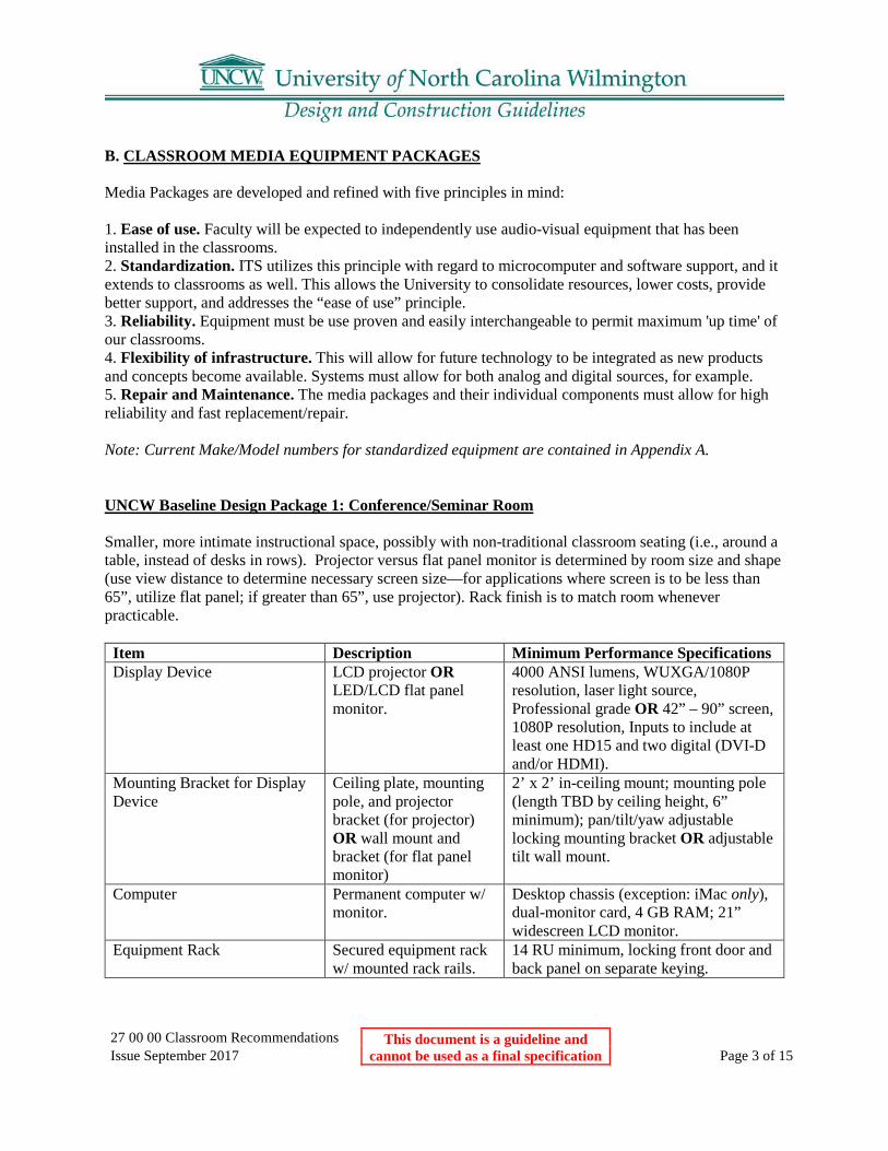
27 00 00 Classroom Recommendations This document is a guideline and cannot be used as a final specification
Issue September 2017 Page 3 of 15
B. CLASSROOM MEDIA EQUIPMENT PACKAGES Media Packages are developed and refined with five principles in mind: 1. Ease of use. Faculty will be expected to independently use audio-visual equipment that has been installed in the classrooms. 2. Standardization. ITS utilizes this principle with regard to microcomputer and software support, and it extends to classrooms as well. This allows the University to consolidate resources, lower costs, provide better support, and addresses the “ease of use” principle. 3. Reliability. Equipment must be use proven and easily interchangeable to permit maximum 'up time' of our classrooms. 4. Flexibility of infrastructure. This will allow for future technology to be integrated as new products and concepts become available. Systems must allow for both analog and digital sources, for example. 5. Repair and Maintenance. The media packages and their individual components must allow for high reliability and fast replacement/repair. Note: Current Make/Model numbers for standardized equipment are contained in Appendix A. UNCW Baseline Design Package 1: Conference/Seminar Room Smaller, more intimate instructional space, possibly with non-traditional classroom seating (i.e., around a table, instead of desks in rows). Projector versus flat panel monitor is determined by room size and shape (use view distance to determine necessary screen size—for applications where screen is to be less than 65”, utilize flat panel; if greater than 65”, use projector). Rack finish is to match room whenever practicable.
Item Description Minimum Performance Specifications Display Device LCD projector OR
LED/LCD flat panel monitor.
4000 ANSI lumens, WUXGA/1080P resolution, laser light source, Professional grade OR 42” – 90” screen, 1080P resolution, Inputs to include at least one HD15 and two digital (DVI-D and/or HDMI).
Mounting Bracket for Display Device
Ceiling plate, mounting pole, and projector bracket (for projector) OR wall mount and bracket (for flat panel monitor)
2’ x 2’ in-ceiling mount; mounting pole (length TBD by ceiling height, 6” minimum); pan/tilt/yaw adjustable locking mounting bracket OR adjustable tilt wall mount.
Computer Permanent computer w/ monitor.
Desktop chassis (exception: iMac only), dual-monitor card, 4 GB RAM; 21” widescreen LCD monitor.
Equipment Rack Secured equipment rack w/ mounted rack rails.
14 RU minimum, locking front door and back panel on separate keying.

27 00 00 Classroom Recommendations This document is a guideline and cannot be used as a final specification
Issue September 2017 Page 4 of 15
Audio System Amplifier; distributed sound speakers; speaker wire.
Amp minimum 6 inputs, incl. 1 XLR, w/ 70 v output; 2’ x 2’ in-ceiling speakers (exact # and placement TBD by room size/shape); 16 AWG (plenum), 3-conductor, shielded.
DVD/VCR or Blu-ray player Media playback device. 1 Composite output for both signals for DVD/VCR; HDMI video output and aux audio outs for Blu-ray player.
Touchscreen Control System Extron or Crestron See A/V Equipment/Instructional Tool Specifics (g. Control System) for details.
Intercom Extron IP Intercom. Stand-alone, 4 button; dedicated Ethernet connection to telecom closet; dedicated unswitched power.
Aux. Inputs Laptop cable(s); USB extension; XLR cable.
25’ HD15 w/ 3.5 mm TRS audio; 6’ HDMI cable; 6’ A (m)–A (f) USB; 6’ M-F XLR
Cable (3x) signal cables from rack to display device.
Plenum, (1x) Analog (2x) Digital, to take interchangeable leads or Plenum CAT6 -- see A/V Equipment Specifics (Cables) for details.
Misc. rack components Power distribution; keyboard drawer; shelves; storage drawer; blanking plates
Rack-mountable surge protector w/ 9 circuits (1 on front) @ 15 A; retractable rack-mountable keyboard drawer for wireless keyboard; 50 lb. capacity shelf; 3 RU storage drawer (no lock); flanged steel blanking plates (size TBD by rack configuration). All of the above are to be in a black anodized finish.
Projection Screen See A/V Equipment/Instructional Tool Specifics (a. Projection screen) for details.
UNCW Baseline Design Package 2: Classroom In instances where podium or lecterns are utilized, equipment rack should fit in unit (adequate ventilation and air flow must be taken into consideration with unit design); otherwise use a 21 RU wall-mount rack.
Item Description Minimum Performance Specifications Display Device LCD projector. 4000 ANSI lumens, WUXGA/1080P
resolution, laser light source, Inputs to include at least one DB15 and two digital (DVI-D and/or HDMI).
Mounting Bracket for Display Device
Ceiling plate, mounting pole, and projector bracket (for projector).
2’ x 2’ in-ceiling mount; mounting pole (length TBD by ceiling height, 6”

27 00 00 Classroom Recommendations This document is a guideline and cannot be used as a final specification
Issue September 2017 Page 5 of 15
minimum); pan/tilt/yaw adjustable locking mounting bracket.
Computer Permanent computer w/ monitor.
Desktop chassis (exception: iMac only), dual-monitor card, 4 GB RAM; 21” widescreen LCD monitor.
Equipment Rack Secured equipment rack w/ mounted rack rails.
14 RU minimum (either rear access panel or sliding; wall units to have locking front door and back panel on separate keying.
Audio System Amplifier; distributed sound speakers; speaker wire.
Amp minimum 6 inputs, incl. 1 XLR, w/ 70 v output; 2’ x 2’ in-ceiling speakers (exact # and placement TBD by room size/shape); 16 AWG (plenum), 3-conductor, shielded.
DVD/VCR or Blu-ray player Media playback device. 1 Composite output for both signals for DVD/VCR; HDMI video output and aux audio outs for Blu-ray player.
Touchscreen Control System Extron or Crestron See A/V Equipment/Instructional Tool Specifics (g. Control System) for details.
Intercom Extron IP Intercom. Stand-alone, 4 button; dedicated Ethernet connection to telecom closet.
Aux. Inputs Laptop cable; USB extension; XLR cable.
25’ HD15 w/ 3.5 mm TRS audio; 6’ A (m)–A (f); 6’ M-F
Cable (3x) signal cables from rack to display device.
Plenum, (1x) Analog (2x) Digital, to take interchangeable leads or Plenum CAT6 -- see A/V Equipment Specifics (Cables) for details.
Misc. rack components Power distribution; keyboard drawer; shelves; storage drawer; blanking plates
Rack-mountable surge protector w/ 9 circuits (1 on front) @ 15 A; retractable rack-mountable keyboard drawer for wireless keyboard; 50 lb. capacity shelf; 3 RU storage drawer (no lock); flanged steel blanking plates (size TBD by rack configuration). All of the above are to be in a black anodized finish.
Projection Screen See A/V Equipment/Instructional Tool Specifics (a. Projection screen) for details.
UNCW Baseline Design Package 3: Auditorium/Lecture Hall Larger venue necessitates brighter projector; tiered seating recommended wherever possible to maximize sight lines and screen footprint.
Item Description Minimum Performance Specifications Display Device LCD projector. If throw distance less than 40’, then
6000 ANSI lumens, laser light source,
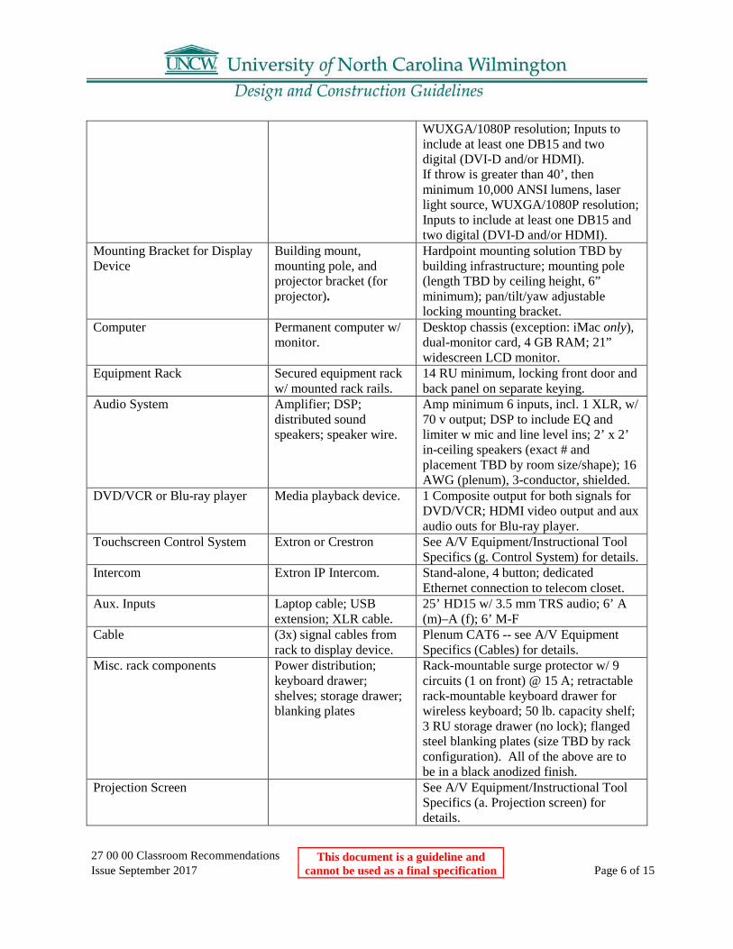
27 00 00 Classroom Recommendations This document is a guideline and cannot be used as a final specification
Issue September 2017 Page 6 of 15
WUXGA/1080P resolution; Inputs to include at least one DB15 and two digital (DVI-D and/or HDMI). If throw is greater than 40’, then minimum 10,000 ANSI lumens, laser light source, WUXGA/1080P resolution; Inputs to include at least one DB15 and two digital (DVI-D and/or HDMI).
Mounting Bracket for Display Device
Building mount, mounting pole, and projector bracket (for projector).
Hardpoint mounting solution TBD by building infrastructure; mounting pole (length TBD by ceiling height, 6” minimum); pan/tilt/yaw adjustable locking mounting bracket.
Computer Permanent computer w/ monitor.
Desktop chassis (exception: iMac only), dual-monitor card, 4 GB RAM; 21” widescreen LCD monitor.
Equipment Rack Secured equipment rack w/ mounted rack rails.
14 RU minimum, locking front door and back panel on separate keying.
Audio System Amplifier; DSP; distributed sound speakers; speaker wire.
Amp minimum 6 inputs, incl. 1 XLR, w/ 70 v output; DSP to include EQ and limiter w mic and line level ins; 2’ x 2’ in-ceiling speakers (exact # and placement TBD by room size/shape); 16 AWG (plenum), 3-conductor, shielded.
DVD/VCR or Blu-ray player Media playback device. 1 Composite output for both signals for DVD/VCR; HDMI video output and aux audio outs for Blu-ray player.
Touchscreen Control System Extron or Crestron See A/V Equipment/Instructional Tool Specifics (g. Control System) for details.
Intercom Extron IP Intercom. Stand-alone, 4 button; dedicated Ethernet connection to telecom closet.
Aux. Inputs Laptop cable; USB extension; XLR cable.
25’ HD15 w/ 3.5 mm TRS audio; 6’ A (m)–A (f); 6’ M-F
Cable (3x) signal cables from rack to display device.
Plenum CAT6 -- see A/V Equipment Specifics (Cables) for details.
Misc. rack components Power distribution; keyboard drawer; shelves; storage drawer; blanking plates
Rack-mountable surge protector w/ 9 circuits (1 on front) @ 15 A; retractable rack-mountable keyboard drawer for wireless keyboard; 50 lb. capacity shelf; 3 RU storage drawer (no lock); flanged steel blanking plates (size TBD by rack configuration). All of the above are to be in a black anodized finish.
Projection Screen See A/V Equipment/Instructional Tool Specifics (a. Projection screen) for details.

27 00 00 Classroom Recommendations This document is a guideline and cannot be used as a final specification
Issue September 2017 Page 7 of 15
ADA IR transmitter See A/V Equipment/Instructional Tool Specifics (c. Audio System) for details.
UNCW Baseline Design Package 4: Laboratory (non specialized) Space devoted mainly to “hands-on” experimentation; need for projector is as secondary teaching aid; the below package may be substituted for the typical Baseline 2 Classroom equipment package at the discretion of ITS. The normal rack and component requirements are mitigated to auxiliary inputs due to pedagogical needs.
Item Description Minimum Performance Specifications Display Device LCD projector. 4000 ANSI lumens, WUXGA/1080P
resolution, laser light source, Inputs to include at least one DB15 and two digital (DVI-D and/or HDMI).
Mounting Bracket for Display Device
Ceiling plate, mounting pole, and projector bracket (for projector).
2’ x 2’ in-ceiling mount; mounting pole (length TBD by ceiling height, 6” minimum); pan/tilt/yaw adjustable locking mounting bracket.
Interface Plates Wall or lectern plate w/ inputs for projector; volume control module for audio system.
Two-gang plate, expandable adapters--(1x) VGA w/ 3.5 mm audio port, (1x) 3-RCA port, (1x) HDMI port. Volume control module may be separate unit.
Audio System Amplifier; speakers; speaker wire.
Ceiling or projector mountable amp--minimum 6 w per speaker, 70 v output; two-way ceiling speakers w/ 70 v transformer and back can (exact # and placement TBD by room size/shape); 16 AWG (plenum), 3-conductor, shielded.
Touchscreen Control System Extron or Crestron See A/V Equipment/Instructional Tool Specifics (g. Control System) for details.
Intercom Extron IP Intercom. Stand-alone, 4 button; dedicated Ethernet connection to telecom closet.
Cable (2x) signal cables from interface plate to display device.
Plenum, (1x) Analog (1x) Digital, to take interchangeable leads or Plenum CAT6 -- see A/V Equipment Specifics (Cables) for details.
Projection Screen See A/V Equipment/Instructional Tool Specifics (a. Projection screen) for details.
UNCW Baseline Design Package 5: Computer Lab In instances where podium or lecterns are utilized, equipment rack should fit in unit (adequate ventilation and air flow must be taken into consideration with unit design); otherwise use a 21 RU wall-mount rack. Computer Labs also require monitoring software for instructor’s computer.

27 00 00 Classroom Recommendations This document is a guideline and cannot be used as a final specification
Issue September 2017 Page 8 of 15
Item Description Minimum Performance Specifications Display Device LCD projector. 4000 ANSI lumens, WUXGA/1080P
resolution, laser light source, Inputs to include at least one DB15 and two digital (DVI-D and/or HDMI).
Mounting Bracket for Display Device
Ceiling plate, mounting pole, and projector bracket (for projector).
2’ x 2’ in-ceiling mount; mounting pole (length TBD by ceiling height, 6” minimum); pan/tilt/yaw adjustable locking mounting bracket.
Computer Permanent computer w/ 2 monitors .
Desktop chassis (exception: iMac only), dual-monitor card, 4 GB RAM; (2x) 21” widescreen LCD monitors.
Equipment Rack Secured equipment rack w/ mounted rack rails.
14 RU minimum (either rear access panel or sliding; wall units to have locking front door and back panel on separate keying.
Audio System Amplifier; distributed sound speakers; speaker wire.
Amp minimum 6 inputs, incl. 1 XLR, w/ 70 v output; 2’ x 2’ in-ceiling speakers (exact # and placement TBD by room size/shape); 16 AWG (plenum), 3-conductor, shielded.
DVD/VCR or Blu-ray player Media playback device. 1 Composite output for both signals for DVD/VCR; HDMI video output and aux audio outs for Blu-ray player.
Touchscreen Control System Extron or Crestron See A/V Equipment/Instructional Tool Specifics (g. Control System) for details.
Intercom Extron IP Intercom. Stand-alone, 4 button; dedicated Ethernet connection to telecom closet.
Aux. Inputs Laptop cable; USB extension; XLR cable.
25’ HD15 w/ 3.5 mm TRS audio; 6’ A (m)–A (f); 6’ M-F
Cable (3x) signal cables from rack to display device.
Plenum, (1x) Analog (2x) Digital, to take interchangeable leads or Plenum CAT6 -- see A/V Equipment Specifics (Cables) for details.
Misc. rack components Power distribution; keyboard drawer; shelves; storage drawer; blanking plates
Rack-mountable surge protector w/ 9 circuits (1 on front) @ 15 A; retractable rack-mountable keyboard drawer for wireless keyboard; 50 lb. capacity shelf; 3 RU storage drawer (no lock); flanged steel blanking plates (size TBD by rack configuration). All of the above are to be in a black anodized finish.
Projection Screen See A/V Equipment/Instructional Tool Specifics (a. Projection screen) for details.

27 00 00 Classroom Recommendations This document is a guideline and cannot be used as a final specification
Issue September 2017 Page 9 of 15
UNCW Baseline Design Package 6: Distance Learning/Videoconference Package information is contained in other documentation due to the special needs of both room and building infrastructure. UNCW Baseline Design Package 7: Collaboration Space This standard is currently under development; consult AV personnel for the latest information on this standard. C. EQUIPMENT AND INFRASTRUCTURE DETAILS 1. A/V Equipment/Instructional Tool Specifics: a. Projection screen. Sometimes it is desirable to install two or more screens for various presentation purposes, especially in Auditorium/Lecture Halls. There are times when faculty will want an image on the projection screen while simultaneously using the whiteboard--this requires careful design so that the screen viewing angle matches line-of-sight to all seating positions while allowing maximum whiteboard space.
1. Provide both motorized and manual units with matte white (gain 1.0) or high-density matte white (gain 1.1) finish, as large as possible for room size.
2. Screens are to have an aspect ratio of 16:10. 3. Align screen so that 50-degree sight lines to the perpendicular centerline cover all seats within the
100-degree cone. 4. Note angle and dimensions on plan to allow exact placement in field. 5. Size screen to room length with a minimum ratio of 1 to 6 (height of screen : viewing distance
from screen). The minimum distance from the whiteboard and/or projection screen to the first row of seating should be at least the width of the image size.
6. Mount all screens as high as possible to maximize viewing area (bottom of screen to be no lower than 36" off the floor unless seating is tiered).
7. Only motorized screens are to be recess mounted. 8. Motorized Main Screen:
a. Recess into ceilings at location identified w/ ITS. b. Mount so that in the down position it will clear wall mounted lights, whiteboards, etc. c. Motorized screen must allow low voltage control. d. Use engraved UP, DOWN, STOP rocker control switch to start the screen movement. e. Control switch is to be installed on same side of projector screen/whiteboard as instructor’s station. f. Do not use momentary screen control switches. Screen units have limit switches that stop operation. b. Whiteboard. All whiteboards should be equipped with marker trays. For classrooms which require large sliding tiered whiteboards, separate corkboards with map hooks should be provided near the front of

27 00 00 Classroom Recommendations This document is a guideline and cannot be used as a final specification
Issue September 2017 Page 10 of 15
the classroom. In all classrooms, whiteboard space should be provided that can be used when the projection screen is down and in use.
1. Include 4' high units in each classroom; set marker tray at 36" AFF. 2. Provide as much whiteboard WRITING surface at the instruction end and sidewalls as possible. 3. Include tack surfaces on each side and back wall in technology rooms to allow special postings. 4. Include board(s) sizes, mounting information and specifications on construction documents. 5. The following should be used when determining the minimum whiteboard size requirements for
classrooms: Conference/Seminar: 3600 mm long x 1200 mm high (12’ x 4’) General Classroom: 6000 mm long x 1200 mm high (20’ x 4’) Auditorium/Lecture Hall 9000 mm long x 1200 mm high (30’ x 4’) OR 3 sections of 3600 mm long x 1200 mm high (3 X 12’ x 4’)
6. Chalkboards may NOT be considered as an acceptable substitute to whiteboards.
(c) c. Audio System. 1. All classrooms are to utilize a distributed audio (mono) via in-ceiling speakers unless there is a
strong, demonstrated instructional/programming need for program speakers (stereo and/or surround sound). See Appendix B for the current list of approved exceptions.
2. A minimum of one auxiliary XLR input is mandatory in any space with an audio system. 3. All systems should have the capacity to interface with assisted listening devices (as per ADA
requirements; see A. CLASSROOM CONSIDERATIONS/ e. ADA Compliance above). 4. Permanent, wall mounted IR transmitters for ADA assisted listening devices are to be installed in
Auditorium/Lecture Halls (earpieces should be readily accessible to users). (d) (e) d. Cables. Given the ever changing and fluid nature of technology, employing a cable
solution that allows for quick, easy, and cheap future expansion is to be desired. Therefore, all cables that convey signal from the equipment rack to the projector should be such that they can accept interchangeable leads (i.e. cable terminations, adaptors, or CAT 6 with interchangeable interfaces).
1. There should be a minimum of three cables pulled for each location, with one capable of conducting 15-pin analog and two conducting HDMI and/or DVI-D digital signals.
2. Each cable will necessitate two leads each—see Appendix A for current termination configurations.
3. Conduit for cable runs should not only accommodate existing cable pulls, but have room for future additions--see Infrastructure Specifics (Conduit) for more details. (f) (g) e. Mounting Brackets. All mounting brackets, for either projectors or flat panel displays,
are to be of the adjustable variety. This allows greater flexibility for minor installation adjustments, ease of access for patching signal and power cables, and for future model upgrades/replacements (for example, physical lens location changing on different model projectors).
(h) (i) Projector brackets:

27 00 00 Classroom Recommendations This document is a guideline and cannot be used as a final specification
Issue September 2017 Page 11 of 15
1. Base plate is to be 2’ x 2’ in-ceiling plate, specifically designed to replace standard suspended-ceiling tile.
2. Base plate should allow some degree of lateral and/or horizontal adjustment of mounting pole position.
3. Base plate is to be properly secured with safety cable to building hard points (as per cut sheets and code using proper hardware).
4. Mounting pole length is determined in part by height of ceiling; the top of the projector lens should be level with the top of the viewing area of the projector screen, so height of pole should be adjusted accordingly.
5. Mounting pole must have cut-out to allow cable run to projector. 6. Projector bracket needs to have pan/tilt/yaw adjustability, as well as locking mechanism for
connecting to projector for theft deterrent purposes. (j) (k) f. Equipment rack. Rack size and type is determined by installation location. Racks
mounted inside podiums or lecterns must allow easy access to back of rack by utilizing sliding rail swivel-type unitand/or a rear access panel.
1. Podium and/or lectern racks need to have a minimum of 14 RU in order to hold full equipment package.
2. Wall mount racks need to have 21 RU (for ease-of-access purposes). 3. All rack rails are threaded (i.e. no rack clips). 4. Front and rear door/access panels are to be keyed separately. 5. Podium and lecterns must be adequately ventilated for the heat load.
(l) (m) g. Control System. Control systems have been added to the baseline standard model, and are
in the process of being retrofitted to all baseline locations. 1. Control systems shall incorporate a minimum 7” touchscreen unless otherwise approved by ITS. 2. Control system shall have the ability to interface with an iPad as a secondary controller for ADA
purposes. 3. Extron and Crestron are the current manufacturers which are approved for deployment, with
Extron systems being deployed in basic packages and Crestron being reserved for complex deployments (such as VTC rooms); ITS shall have final approval for which manufacturer is used where.
4. Touchscreen position TBD by ITS; in instances where unit will be wall mounted, supporting infrastructure (back box, data drop, power, conduit) shall be installed by the GC.
5. Programming for these systems shall be done by manufacturer certified personnel; ITS shall determine which certifications are appropriate to meet this standard. (n) (o) h. IP Intercoms. Given safety and health concerns, intercom systems have now been adapted
as part of the basic instructional space package. The University has selected Extron to be the vendor of choice, and any intercom system must interface with their software so that one unified system covers all of campus.
1. All instructional spaces are to get a multi-channel intercom (i.e. multiple buttons). 2. Intercoms are unidirectional, and are to utilize the data network for transmission of all signals. 3. Each intercom is to have its own dedicated Ethernet connection. 4. Power for each unit is to be secure and non-switched, either by being behind a lock rack, mounted
above the ceiling, or by running a low-voltage line to the closest EH&S closet.

27 00 00 Classroom Recommendations This document is a guideline and cannot be used as a final specification
Issue September 2017 Page 12 of 15
2. Infrastructure Specifics a. Ethernet/Data. Ethernet specifications for classrooms are contained in the Telecommunications/Networking documentation. All equipment racks require the data ports to be located inside rack enclosure unless otherwise approved by ITS. b. Conduit. A/V conduit refers to the pathway between the equipment rack location and the LCD projector. Conduit and pathway should meet all code, University standards, and industry standard “Best Practices.” All A/V conduit must have a minimum 1 1/4” diameter, except for Auditorium/Lecture Halls and Distance Learning/Videoconference spaces which require a minimum 2” diameter. c. Power. Power is required for both the equipment rack and ceiling projector position. Each location should be on isolated circuits to prevent ground loops and other interference that may adversely impact the system. Power receptacle in ceiling should be mounted in projector plate wherever possible, and should utilize flexi-conduit with enough leeway to allow plate to shift 3’ in any direction from marked emplacement. Power runs and receptacles should meet all code, University standards, and industry standard “Best Practices.” d. Lighting. General guidelines for the selection of light fixtures should include the use of recessed lamps in sharp cutoff luminaries to provide controlled lighting with minimal light spill on projection screens and to avoid shining light directly in the audience's view. The use of incandescent lamps should be avoided in order to reduce maintenance, conserve energy, and reduce heat generation.
1. The first row of lights in a room, specifically those that illuminate the instructional area including whiteboard and projection screen, should be controllable separate from the rest of the room lighting (allows instructor to illuminate whiteboard properly while reducing ambient light spill on screen when using projector).
2. All light switches shall be clustered, simple to use, with clearly labeled functions on the switch plates.
3. Light controls should be conveniently located close to the entrance doors, and duplicated at the whiteboard. When locating controls at front of room, they should be located as closely adjacent to instructor’s station as possible.
4. Aisle lights (on a separate circuit) should be provided in tiered Lecture Halls, in order to prevent late arriving students from tripping in the dark.
5. Fluorescent light fixtures shall have dimmable electronic ballasts with parabolic louvers to have reduced grid size to minimize horizontal light spill and glare.
6. Hanging fixtures must not be placed between existing/new/future ceiling mounted projectors and screens.

27 00 00 Classroom Recommendations This document is a guideline and cannot be used as a final specification
Issue September 2017 Page 13 of 15
Appendix A Current Baseline Make/Model—June, 2015
Item Manufacturer Model LCD Flat Panel Monitor LG, Samsung, or Sony Professional-grade monitor
required Mounting Bracket for 42”- 50 “ FPM Chief MSMVU FUSION or MTM1U Mounting Bracket for 50+” FPM Chief LSMVU FUSION or LTM1U LCD Projector--4000 lumens, WUXGA resolution (16:10 aspect)
Sony VPL-FHZ57 OR VPL-PHZ10 (TBD by throw requrements)
LCD Large Venue Projector--6000 lumens, laser light source, WUXGA resolution (16:10 aspect)
Sony VPL-FHZ65 or VPL-FHZ700L; lens TBD by screen size/throw distance.
LCD Large Venue Projector-12,000 lumens, laser light source, WUXGA resolution
Barco F90-W13; lens TBD by screen size/throw distance.
Mounting Bracket, Ceiling plate Premier Mounts PP-FCMA Mounting Bracket, Mounting Pole Extron PMP series (length TBD by
installation location) Mounting Bracket, Ceiling plate Chief RPMA-020 or RPMB-020 for
VPL-FHZ55 (specified as “A” or “B” by ITS as per installation owner); VCM29S for VPL-FH500L
Computer Dell or Apple Optiplex 7040 Desktop or Small
Form Factor chassis (via UShop Dell Punchout) or iMac
Computer Monitor, 16:9 aspect Dell P2217H (via UShop Dell Punchout) Equipment Rack/Lectern Middle Atlantic or Spectrum
Furniture Model TBD by location (ITS to approve); (SF) Freedom XRS or Honors
Amplifier Extron, Crown TBD (Extron, Crown, QSC) Touch Screen Control System Extron (preferred) or Crestron Model(s) of componants contingent
upon design needs. Default switcher/scaler is IN 1608 IPCP 70 MA

27 00 00 Classroom Recommendations This document is a guideline and cannot be used as a final specification
Issue September 2017 Page 14 of 15
DSP Biamp or Extron Extron: DMP 64 or DMP 128; Biamp: Audia, Nexia (VT), or Tesira
Speakers, 2’ x 2’ 70v Extron FF 220T Microphones Sennheiser or Shure TBD Assisted Listening devices Sennheiser TBD by location; typically IR Blu-Ray Oppo TBD IP Intercom Extron IPI 204 Laptop cable Extron Analog: VGA-A M-M MD/25 (part
# 26-490-04); Digital: HDMI Pro/12 (part # 26-650-12)
Cable (CAT 6) See Networking and
Communications standards for list of acceptable Manufacturers and models.
Rack Component (power distribution; surge protector)
Middle Atlantic or SurgeX (MA) PD-915R or RLNK-SW815R-SP; (SX) SX-AX15 or SX-AX15E
Rack Component (keyboard drawer) Middle Atlantic KB-SS Rack Componant (utility shelf) Middle Atlantic U2 series Rack Component (utility drawer) Middle Atlantic UD series Rack Component (blanking plate) Middle Atlantic EB series Document Camera WolfVision or Lumens (WV) PZ-8plus4 or PZ-9plus4; (L)
DC 170 or DC 193 Projection Screen Da-Lite, Draper, Stewart Model TBD by application (16:9 or
16:10 aspect) Projection Screen Da-Lite, Draper, Stewart Model TBD by application (16:9 or
16:10 aspect) Computer monitoring Software LanSchool Version TBD based on current
UNCW software licensing.

27 00 00 Classroom Recommendations This document is a guideline and cannot be used as a final specification
Issue September 2017 Page 15 of 15
Note: Control systems and a few other subsystems are not listed here; for determining the specific make/models contact ITS. Appendix B Current Pre-Approved Baseline Exceptions—September, 2013 (Items on this list have been pre-approved due to the specific program/instructional necessities of the Department as a whole. Approval on this list constitutes permission to add the specific item only; all funding for baseline exceptions are the sole responsibility of the requesting party) Document Camera
• Rooms belonging to Mathematics and Chemistry are required to have doc cams as part of their baseline standard equipment. Any other department may add a document camera to the baseline package at the discretion of ITS.(sometimes colloquially referred to as an “ELMO”).
• Any document camera used at the University must have at least 1080P resolution, 30 fps, and digital output (either DVI-D or HDMI).
Camera Microscopes
• Specific model can be determined by utilizing Department, as long as the following standards are adhered to:
1. Camera must output to one of the following connector types: HD15 (VGA), DVI-D, HDMI, or USB.
2. Any cable runs to connect camera to equipment rack are the responsibility of the requesting Department, and must meet all code/safety requirements for installation.
Stereo/Surround Sound Audio
• The only departments pre-approved to deviate from 70v distributed audio are Film Studies, Music, Theatre, and Communication Studies; large-venue auditoriums may be considered on a per-case basis. Additional consideration may be granted in instances where a videoconferencing system is to be installed. If a baseline system is being installed in a CTAP room, the requesting department will be responsible for any resulting increase in cost for the new equipment over the baseline. Specific model of amp and placement speakers will be determined by ITS and the requesting Department.

27 05 00 UNCW Telecommunications This document is a guideline and cannot be used as a final specification
Issue September 2017 Page 1 of 1
27 05 00 UNCW Telecommunication Standards The Project Manager should contact ITSD for an updated transmittal of the current standards.

28 13 00 UNCW Access Control This document is a guideline and cannot be used as a final specification
Issue September 2017 Page 1 of 1
28 13 00 UNCW Standards for Installation of Access Control Equipment The Project Manager should contact UNCW for an updated transmittal of the current “Physical Security and Access” standards.

28 16 00 UNCW Intrusion Systems This document is a guideline and cannot be used as a final specification
Issue September 2017 Page 1 of 1
28 16 00 UNCW Guidelines for the Installation of Intrusion/Burglary Systems The Project Manager should contact UNCW for an updated transmittal of the current “Physical Security and Access” standards.

28 23 00 UNCW Camera Systems This document is a guideline and cannot be used as a final specification
Issue September 2017 Page 1 of 1
28 23 00 UNCW Standards for Installation of Cameras and Camera Systems The Project Manager should contact UNCW for an updated transmittal of the current “Physical Security and Access” standards.

28 31 13 Fire & Security Alarm Systems This document is a guideline and cannot be used as a final specification
Issue September 2017 Page 1 of 5
28 31 13 Fire & Security Alarm Systems
Part 1: General Design Guidelines
1.01 All designs and system installations shall be in accordance with the latest version of the North Carolina State Construction Office “Fire Alarm Guidelines and Polices” document, NC State Construction Office “Electrical Guidelines and Policies” document, the most recent adopted version of relevant National Fire Protection Association (NFPA) Standards, and UNCW design & construction standards. Any deviations from these Guidelines and Standards must have written approval from the UNCW Architectural & Construction Services, the UNCW Physical Plant, and the UNCW Environmental Health & Safety Department. Designers/engineers shall closely monitor and thoroughly inspect the system design and installation to ensure compliance with these requirements. A. Renovations or modifications to existing buildings that alter the layout/design from the
original approved & accepted design shall require fire alarm redesign approved by NC State construction Office AHJ to accommodate changes to the building. All fire alarm system alterations/modifications to accommodate building changes shall comply with all of the standards in UNCW Part 1 1.01 General design Guidelines.
B. Detailed and comprehensive specifications shall be prepared for all projects and shall include, but not limited to, specification manuals and detail drawings.
C. A pre-design meeting is required with the design engineer for all new fire alarm systems, system replacement/upgrades, or significantly altered fire alarm systems (addition/removal of devices).
D. A pre-construction meeting is required with the engineer, electrical contractor, fire alarm contractor, UNCW project manager, and UNCW fire alarm technician for all new fire alarm systems or major replacements/upgrades.
1.02 All fire alarm systems shall be of the addressable type, 24 VDC nominal operating voltage, and in compliance with NC State Construction Office requirements, NFPA Standards, and “UL” Listings.
1.03 All work on alarm systems will be done by workers experienced and qualified in the installation of alarm systems and shall be knowledgeable of the workings and installation requirements of the respective alarm system.
1.04 “NOTIFIER” brand fire alarm system control panels and components are the campus standard and shall be specified as a preferred manufacturer alternate. A. “System Sensor” brand is the preferred manufacturer for notification devices.
1.05 During the fire alarm “programming stage” consult with the system design engineer, UNCW lead fire alarm technician & UNCW Environmental Health & Safety to determine if alarm verification feature shall be turned on.
1.06 A password protected silent walk test feature shall be provided in the fire alarm system operation. As an alternate, a password protected means to bypass notification devices shall be provided in the fire alarm software programming to allow maintenance and testing while the building is occupied.

28 31 13 Fire & Security Alarm Systems This document is a guideline and cannot be used as a final specification
Issue September 2017 Page 2 of 5
This alternate method shall not require more than ten devices to be entered for bypassing notification in the building.
1.07 All contracts & project specifications pertaining to fire alarm and smoke detection systems shall include an “assurance of performance” clause. Nuisance alarms due to improper placement/application of devices or other repeat abnormalities causing issues within the system shall require corrective action by the engineers and/or installers to resolve the problem at no cost to UNCW. Corrective actions will require a retest of the system. Corrective actions can be up to and including full replacement of the system if necessary.
1.08 Security and Life Safety (fire alarm, panic, hold-up, environmental, etc.) communication dialers (DACT’s) shall be compatible with UNCW’s central alarm receiver and its current software version. Compatibility shall be confirmed with university personnel prior to any installation. Non-compatible items/systems shall be removed and replaced at the contractor’s expense. A. Acceptable alarm transmission formats are 3+1 standard or 4+2 standard. Contact ID is not
an acceptable transmission format.
1.09 “DITEK” brand is the preferred brand for surge suppression/protection on fire alarm signal and notification circuits, fire alarm and security panel phone lines, and 120-volt AC electrical power supply.
1.10 All fire alarm wiring shall be installed in metal conduit. A. Minimum size of any conduit for fire alarm and security applications shall be ¾” trade size. B. All EMT conduit fittings shall be of all steel construction and of the compression type. C. Seal all raceway penetrations between conditioned and unconditioned environments or
extreme temperature differences to prevent condensation issues. D. Nonmetallic raceway is acceptable for belowground applications outside the building.
1.11 Splices (junctions) shall not be made in system wiring (except as specified inside terminal cabinets between floors of buildings). Fire alarm wiring for signaling, notification, and control shall be continuous without splice between devices, control panel boards, or terminal cabinets.
1.12 Terminal cabinets shall be minimum size of 10”x10”x4” and be accessible from standing floor level without the use of a ladder.
1.13 One copy of the fire alarm detection & initiating device installation shall be mounted beside the fire alarm control panel and each remote annunciator. This fire alarm installation wall chart shall indicate: (1) floor plan of each floor within the building; (2) location of all detection & initiating devices with their device address; (3) location of the fire alarm control panel, (4) all room numbers. A. Alterations to building floor plans shall require fire alarm charts to be replaced with updated
plans as part of the project that required the change to building floor plans. Hand draw copies are not acceptable.
1.14 At the time of beneficial occupancy, an electronic/digital copy (USB/flash drive) of the fire alarm drawings in a PDF format shall be provided to UNCW for use by maintenance personnel until

28 31 13 Fire & Security Alarm Systems This document is a guideline and cannot be used as a final specification
Issue September 2017 Page 3 of 5
complete final documentation is delivered at project closeout. These electronic drawings shall include system design drawings, construction as built wiring, system wiring details, wire termination numbers in all control panels, booster power supplies, terminal cabinets, and control/modules. This electronic copy of the drawings is in addition to any hardcopies required by the project specifications and standards.
1.15 Maintenance manuals in an electronic/digital format (USB/flash drive) shall be provided to UNCW at the time of beneficial occupancy and shall include installation, programming, and operation manuals, applicable cut sheets, technical information, and electronic circuit diagrams of all control panel layouts, modules, annunciators, communicators, power supplies, and all other components installed in the system. This electronic copy of the required maintenance manuals is in addition to any hardcopies required by the project specifications and standards.
1.16 In addition to spare parts required by the NC State Construction Office document “Fire Alarm Guidelines and Polices”, the project specification/guidelines shall require one of each type of fire alarm field component (excluding projected beam, air sampling devices) be supplied to UNCW at the time of beneficial occupancy (i.e. a minimum of one of each type notification device, module, control relay, detector, surge suppressor, etc.).
1.17 Smoke detectors shall not be installed in ceilings over the mid-point stairwell landings unless the ceiling height is 12 feet or less to the landing. For high ceiling areas use the Projected Beam type smoke detector if detection is required in the stairwell. Smoke detectors shall not be mounted over stair steps. A. Notifier smoke detector model FAPT-851 are not allowed for use on new or renovation
projects.
1.18 All device and pull boxes shall be securely mounted to the building. Device boxes installed in lay-in ceilings shall be supported in addition to the ceiling grid attachment.
1.19 Monitor, relay, or control modules shall not be installed above ceilings. They shall be accessible from floor level without the use of ladders. A. Exception: Relays for damper control are permitted to be mounted into lay-in ceiling grid.
1.20 When it is possible and practical design fire alarm systems without the use of duct smoke detectors. The environment for this region makes this type of detector highly susceptible to nuisance alarms and failures due to moisture issues. Where duct detectors must be used they shall use a twist out, removable smoke detector.
1.21 The voltage shall be verified on each notification appliance circuit at the end of the line under full load on battery backup. The voltage will be measured after 5 minutes run time under full load and compared to allowable tolerances.
1.22 The fire alarm digital alarm communicating transmitter (DACT) shall be monitored by the fire alarm panel or shall be integral to the fire alarm panel CPU circuit board so that loss of telephone service will result in a trouble alarm on the fire alarm control panel. The trouble alarm resulting from problems with the DACT shall be capable of being silenced from the fire alarm control panel keypad. The fire alarm DACT shall be provided with two telephone lines for redundant dial out

28 31 13 Fire & Security Alarm Systems This document is a guideline and cannot be used as a final specification
Issue September 2017 Page 4 of 5
capability. When the DACT is not an integral part of the fire alarm control panel circuit board it shall be placed in a separate keyed enclosure adjacent to the fire alarm control panel. DACT’s which are not an integral component of the fire alarm CPU circuit board are not allowed to be installed inside the fire alarm control panel enclosure.

28 31 13 Fire & Security Alarm Systems This document is a guideline and cannot be used as a final specification
Issue September 2017 Page 5 of 5
1.23 Fire alarm control panels, booster power supplies, DACT, amplifier racks, terminal cabinets, and other similar enclosures shall not be used as raceways for cables or conductors that do not originate or terminate within the enclosure.
1.24 Cables or conductors from other systems cannot share fire alarm system raceway. This includes but is not limited to telephone cables, elevator recall conductors, AHU shutdown circuits, etc.
1.25 All fire alarm panel software access codes shall be provided to the lead UNCW Fire Alarm Technician at the completion of all projects.
1.26 The fire alarm control panel shall be capable of being programmed on site from the control panel keypad interface in addition to the use of a laptop computer connected to the control panel. The changing of EPROMS is not acceptable. A. Fire alarm system equipment shall be fully serviceable by UNCW personnel. Proprietary
equipment with restricted access is not acceptable. B. Smoke detectors or other addressable fire alarm system devices that are addressed by the fire
alarm control panel or the use of a hand held programming device are not acceptable.
1.27 All equipment and components shall be installed according to the manufacturer’s listed instructions and all applicable codes and standards.
1.28 AHU shutdown during fire alarm shall be accomplished by addressable control relays controlled through the fire alarm control panel software. Utilizing smoke detector relay bases or the relay contacts on duct smoke detectors to achieve AHU shutdown is not allowed.
1.29 “Ademco” by Honeywell is the preferred brand of intrusion/burglary panel hardware. 1. Any new intrusion/burglary system must be approved in writing by UNCW Police prior to
installation. Consult with UNCW Police before planning any system installation. 2. Any approved intrusion/burglary system must be compatible with the central alarm
receiver at UNCW Police department. Consult with UNCW Electrical Services alarm technicians to assist with determining system compatibility.
3. Wireless type sensors are prohibited for use at UNCW. Examples include but are not limited to door contacts, motion sensors, beam detectors, panic buttons, and glass break sensors. All installed sensors & accessories must be hardwired to the system control panel.

32 00 00 Exterior Improvements Issue September 2017 Page 1 of 4
32 00 00 Exterior Improvements
Part 1: Parking Lot Design & Campus Paths
1.01 Design Criteria A. General – Off-street parking shall alleviate street congestion, allow for efficient vehicular
capacity, consider vehicular visibility when backing, and reduce adverse impacts to environmentally sensitive areas. Continuous traffic flow, safe pedestrian/user movement and appropriate levels of landscape and lighting shall be implemented. Parking lots may be constructed with asphalt, concrete, pervious or impervious paver systems and/or gravel when deemed appropriate by UNCW.
B. Layout – Safety and welfare of all pedestrians/users shall be top priority within design. Parking facilities need to consider movements of fire trucks, tow trucks and other emergency vehicles. Cars should not have to back in to public rights of way to exit a parked position.
C. Dimensional Standards – Standard or typical parking spaces shall be 9’ wide by 18’ deep unless stalls are on an angle, see below for specifics regarding angles parking spaces. Compact spaces may be approved by the University on a case by case basis. Parking bays can be arranged to allow for 90 degree, 60 degree and/or 45 degree parking per cart below. Parallel spaces shall be, a minimum of, 8’ in width and, a minimum of, 20’ in length. Curb and gutter shall be used in all parking lots per NCDOT standards? Parking Stall Dimensions
D. Stormwater & Drainage – All Stormwater shall be directed to a Stormwater drainage system.
If permeable pavement systems are used, infiltration is acceptable based upon design intent of cross section and surface material. See Part 2 and Part 3 for more detail related to Drainage and Retention/Detention facilities.
1.02 Circulation & Accessibility

32 00 00 Exterior Improvements Issue September 2017 Page 2 of 4
A. Layout & Routing – Consideration to all pedestrian movements shall be considered, however routing shall focus on main entries and exits. Promoting and reinforcing paths of travel must be integrated into the design to minimize maintenance and wear of landscaped areas. One accessible route from parking to facility or facilities the lot is serving must be achieved.
B. Sidewalks, Ramps & Handrails – See section 32 00 00, 1.08 for more detail related to pedestrian paths. Accessible sidewalks and ramps shall never exceed 1:12 in the direction of travel. Cross slopes on all sidewalks and ramps shall never exceed 2%. Ramps must be provided at curbs or other raised barriers to provide access to the accessible routes leading from the parking lots. Widths must meet ADA Guidelines at time design is being completed. Handrails must conform to the latest requirements within the ADA Guidelines.
C. Accessible Space Design & Location – Spaces for disabled persons must conform to the most current ADA Guidelines at time of parking lot design. Soft or loose surfaces are not appropriate for accessible spaces or routes.
D. Bus Stops – Coordination with UNCW Planning, Facilities and Transportation shall occur in regard to existing, proposed and/or potential on-site covered bus stops. Safe connections to and from parking facilities shall be provided.
1.03 Pavement Striping and Marking A. Layout –All paved parking lots shall delineate spaces with markings. Traffic lanes,
circulation aisles, parking zones, special spaces and other features may be required. Markings shall be in accordance with the Manual of Uniform Traffic Control Devices or as otherwise approved by UNCW. Markings and signs shall be kept well maintained and in serviceable condition.
B. Signage – Handicapped, emergency vehicle, restrictions/requirements and/or any other UNCW directives shall be posted visible to all and easily understood.
C. Painting & Marking – See section 32 12 16 Asphalt Paving for more detail. Pavement marking at driveway locations for high traffic generators shall be thermoplastic. Other required markings may be either thermoplastic or approved traffic paint with approval from UNCW. Markings shall not be applied until pavement has been allowed to cure sufficiently to allow volatiles to escape. Any faded, peeled or damaged markings due to early application shall be reinstalled at no cost to UNCW. All parking stall paintings shall be white.
D. Materials & Details – All materials and details shall be in accordance with NCDOT standards.
1.04 Barriers & Barricades A. Wheel stops –Wheel stops shall be required 3’ from the end of stall when using 18’ deep
stalls. Curbing, crossties and other acceptable material by UNCW may be used and must be anchored into the ground.
B. Gates – Used to restrict use of parking to individuals with pre-approved permission. Gates may be two-way gate systems or a single gate with controlled egress. The preferred alterative is the MHTM Microdrive Magnetic Access Barrier.
C. Bollards – See Section 12 93 00, 1.05/1.06 for more detail related to bollard specifics.
1.05 Landscaping A. General – Parking lot landscaping is intended to minimize visual impact of vast expanses of
vehicular areas from public or private streets while reducing heat island effects. Design of lots shall break mass of spaces using planted islands (end cap and median between bays). Plant locations and arrangement shall always consider user safety, security, and pedestrian circulation and visibility. Leaves, fruit and other litter possible from plant material shall be

32 00 00 Exterior Improvements Issue September 2017 Page 3 of 4
considered to minimize maintenance and damage/impact to adjacent hardscape surfaces and buildings. All plant material specifications are to meet the American Standard for Nursery Stock. See section 32 90 00 Landscaping Design Guidelines for more detail related to plant, mulch, turf, installation and maintenance requirements
B. Tree & Shade Requirements – One tree per every 10 parking spaces is required unless otherwise approved by UNCW. Trees shall be located, at minimum, 15’ from light poles.
C. Island & Perimeter Landscape – A landscaped island must be provided every 12 parking spaces unless otherwise approved by UNCW. Interior islands must be 8’ in width, minimum, from back of curb to back of curb. Rows of parking must terminate with an island where a tree, light pole, fire hydrant or other utility structure may be located. No more than 48 spaces in a row can be accepted without an aisle for ease of vehicular circulation. Median islands shall be, a minimum, of 6’ in width unless a sidewalk is provided the overall width shall be, a minimum, of 12’. Perimeter islands must be, a minimum, of 6’ in width and shall be provided along internal access drives and adjacent streets. Perimeter landscape strips shall be, a minimum, of 6’ in width and planted at a rate of 30 shrubs per 100’ and 1 tree per 40’. Landscaped islands shall include provisions for water and electricity. See Section 32 90 00 Landscaping Design Guidelines for more detail related to plants, shrubs and turf.
1.06 Irrigation A. See Section 32 90 00, Part 8 of the Landscaping Design Guidelines for more detail.
1.07 Security & Lighting A. Emergency Call Stations – These shall be located conveniently and accessible as they are
intended to be used to call security of police during an emergency situation. B. Pathway Lighting – Shall always be provided for safety. Adequate foot candles shall be
provided and confirmed by a photometric layout. All fixture and pole assemblies shall be black. The preferred alternative is the C24 Call Box. See Section 26 56 00 for more detail related to lighting.
C. Parking Lot Lighting – Shall always be provided for safety. Adequate foot candles shall be provided and confirmed by a photometric layout. Light poles shall be located, at minimum, 15’ from tree locations. All fixture and pole assemblies shall be black. See Electrical specification 26 56 00 and Section 26 00 00 for more detail related to lighting and fixture assemblies.
1.08 Pedestrian Paths A. Pedestrian paths shall be constructed of asphalt, concrete and/or concrete or brick pavers. If
pavers are used, appropriate paver ratings shall be installed to address possibility of heavy duty traffic. Gravel, mulch, wood decking or other materials shall be acceptable by UNCW on a case by case basis dependent on location and purpose of path.
1.09 Bicycle Paths A. Bicycle paths shall be signed and marked in order to create safe environments understood by
users. Bicycle path design and construction shall be in accordance with North Carolina Department of Transportation Guidelines and Standards, latest version. Parking lots should also consider the University Bike Share Program.
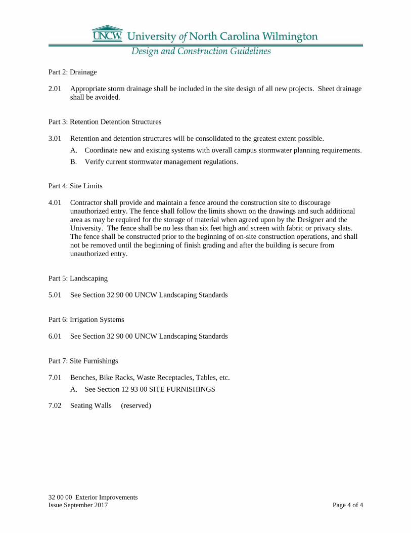
32 00 00 Exterior Improvements Issue September 2017 Page 4 of 4
Part 2: Drainage
2.01 Appropriate storm drainage shall be included in the site design of all new projects. Sheet drainage shall be avoided.
Part 3: Retention Detention Structures
3.01 Retention and detention structures will be consolidated to the greatest extent possible. A. Coordinate new and existing systems with overall campus stormwater planning requirements. B. Verify current stormwater management regulations.
Part 4: Site Limits
4.01 Contractor shall provide and maintain a fence around the construction site to discourage unauthorized entry. The fence shall follow the limits shown on the drawings and such additional area as may be required for the storage of material when agreed upon by the Designer and the University. The fence shall be no less than six feet high and screen with fabric or privacy slats. The fence shall be constructed prior to the beginning of on-site construction operations, and shall not be removed until the beginning of finish grading and after the building is secure from unauthorized entry.
Part 5: Landscaping
5.01 See Section 32 90 00 UNCW Landscaping Standards
Part 6: Irrigation Systems
6.01 See Section 32 90 00 UNCW Landscaping Standards
Part 7: Site Furnishings
7.01 Benches, Bike Racks, Waste Receptacles, Tables, etc. A. See Section 12 93 00 SITE FURNISHINGS
7.02 Seating Walls (reserved)

32 12 16 Asphalt Paving Issue September 2017 Page 1 of 5
32 12 16 Asphalt Paving
Part 1: General Requirements
1.01 Asphalt Paving
1) Paving Design shall conform to latest NCDOT Design Standards.
1.02 Roadways
1) Roadway Design shall conform to latest NCDDOT Design Standards.
1.03 Parking Lots
1) Parking Lot design shall follow:
A. City of Wilmington standards as a minimum.
1.04 Bike Paths
1) Use the NCDOT Bicycle Facilities Planning and Design Guidelines as a reference.
Part 2: Typical Details and Materials

32 12 16 Asphalt Paving Issue September 2017 Page 2 of 5
2.01 Speed Hump with Crosswalk Detail

32 12 16 Asphalt Paving Issue September 2017 Page 3 of 5
2.02 Decorative Asphalt
1) Basis of Design Product: “StreetPrintXD” by Intergrated Paving Concepts Inc.

32 12 16 Asphalt Paving Issue September 2017 Page 4 of 5
2.03 Typical Speed Hump

32 12 16 Asphalt Paving Issue September 2017 Page 5 of 5
2.04 Large Speed Hump

32 90 00 Landscaping Design Guidelines Issue September 2017 Page 1 of 19
32 90 00 UNCW Landscaping Standards
Part 1: Applicability
1.01 These guidelines are for use for all UNCW properties. A. These guidelines include design, material and methods, and warranties for the following:
1. Planting, including trees and shrubs. 2. Lawns and Grasses 3. Tree protection 4. Irrigation
Part 2: Design Guidelines – General
2.01 All new buildings shall have related landscaping and irrigation designed and installed as part of the project.
2.02 In natural areas and designated native themed areas, plant only native plants.
2.03 Use ornamentals sparingly at building entrances and corners for clear lines of visibility for safe traffic movement.
2.04 No annual planting beds are desired except as directed by UNCW Landscape Services.
2.05 Foundation plantings shall be planted so that at maturity, maintenance personnel can walk between the building face and the plant material, landscaping will be offset from buildings a minimum of 6 feet, and will be designed so as not to block windows when plantings are mature. Mature plant size will address building penetrations, blank walls, windows, etc.
2.06 Provide a mulch strip at the base of the building where earth meets the building base.
2.07 Arrange plant material with safety and security issues in mind. Plant material over 3 feet in height at maturity shall be 10 feet back from the edge of walkways to ensure visual clearances.
2.08 Street trees shall be planted on every street to provide shade over the pavement. Coordinate street tree plantings with street lighting.
2.09 Locate larger trees so that leaves do not collect on rooftops.
2.10 Each tree shall have a 6-foot diameter minimum mulch ring.
2.11 Where possible locate trees in groupings within a continuous mulch bed for ease of mowing. In general, locate trees a minimum of 10 feet from paved areas.
2.12 All plant material specifications are to meet Nursery standards or better.

32 90 00 Landscaping Design Guidelines Issue September 2017 Page 2 of 19
2.13 Landscape and site designs should preserve existing trees to the maximum extent possible.
2.14 All new landscape construction will be designed with an irrigation system.
2.15 All parking lot designs are to include large islands with landscaping, electricity, and water at each island.
Part 3: Design Guideline – Designer Responsibilities
3.01 The Designer is responsible for: A. Including applicable UNCW guidelines in the landscape plans and specifications. Additional
instructions and materials may be added as determined by the Designer (Landscape Architect).
B. Providing a description of the scope of the work on the Plans and Specifications. C. Initiating a thorough evaluation with UNCW Landscape Services and the University Arborist
with any proposed to remove an existing tree before committing to a design strategy. D. Specifying the common name and the botanical name in the plans. E. Locating for the contractor at least one plant source for each plant type specified. F. Providing irrigation plans from a scope of irrigation determined with UNCW Landscape
Services. As-Builts due at final inspection. G. Providing a maintenance plan for the plant material and a description of long term
maintenance goals for the landscape.
Part 4: Design Guidelines – Warranties
4.01 Contractor’s Maintenance Responsibilities Until Final Acceptance: A. Maintenance and protection of the work is the responsibility of the Contractor until Final
Acceptance. Maintenance shall consist of mowing, watering, cultivation, weeding, mulching, resetting of plants to proper grades or upright positions, keeping the plants free of insects and disease and in thriving condition.
B. If any chemical application is required during installation or the maintenance period, a copy of the applicator’s license shall be provided to the UNCW Construction Manager at the time the contract is executed.
C. It shall be the responsibility of the Contractor to provide security or barricade the plants to prevent damage to work in place and to keep the site neat and clean in appearance until the Final Inspection.
4.02 Final Acceptance A. After Final Acceptance, the Owner will assume all maintenance of plant material (mowing,
cultivation, weeding, mulching, keeping the plants free of insects and disease) of the site. Exceptions include the Contractor responsibilities for watering as defined in the warranty period. The Contractor shall submit to UNCW Landscape Services two copies of typewritten maintenance plans with instructions for caring for new plantings for one full year. The Owner shall keep records of maintenance practices during the warranty period.

32 90 00 Landscaping Design Guidelines Issue September 2017 Page 3 of 19
4.03 Warranty Period Requirements A. Usually, the warranty period shall be for 12 months from the date of Final Acceptance for
plant material. The warranty period shall be for 24 months from date of Final Acceptance for non-irrigated trees of 3” or larger caliper. For all non-irrigated plant material, the Contractor is responsible for ensuring the plants receive the equivalent of 1” of water per week during the guarantee period of one year. If the warranty period extends to 2 years, water 1” of water every two weeks in the second year.
B. The Contractor shall keep watering and maintenance records submitted monthly during the warranty period to UNCW Construction Management.
C. The warranty requires that plants be healthy, vigorous, and thriving for 12 months from the date of Final Acceptance. Any replacement plants shall be inspected by the Designer and UNCW Landscape Services and Project Manager prior to planting to ensure plants are closely matched.
D. Dead or dying plants will be documented and removed immediately by the Contractor. E. At the end of the warranty period the Designer will notify UNCW Construction Manager and
the Contractor in writing of the plants to be replaced. Replacement dates will be established by mutual agreement between the Designer, UNCW Landscape Services, and the Contractor. New plants shall be subject to the original warranty for that plant.
Part 5: Design Guideline – Plant Material and Methods
5.01 Plants: A. The Contractor must provide a list of sources for all plant material for the Designer’s review. B. To substitute plants shall be ordered by the Contractor without the written approval of the
Designer with agreement from UNCW Project Manager and UNCW Landscape Services. C. All plants must conform to the American Standard for Nursery Stock published by the
American Association of Nurserymen. D. Plants larger than specified may be used if approved by the Designer. Use of such plants shall
not increase the contract price. If larger plants are approved, the soil preparation must be increased to accommodate the size of the plant at no additional cost to the owner.
E. Plants shall be measured when branches are in the normal position. Height and spread dimensions refer to the main body of the plant and not branch tip to tip. If a range of size is given, no plant shall be less than the minimum size and not less than 40% of the plants shall be as large as the maximum size specified. The measurements specified are the minimum size acceptable. Plants that meet the measurements specified, but do not have a normal balance between height and spread shall be rejected.
5.02 Herbicide - Post-emergent: A. Herbicide: “Round-Up” by Monsanto or equal 41% Glyphosate product, mixed with field
marker, (written statement for future reference). B. Pre-emergent: XL2G or Snapshot (depending on plant crop) or equal, after an approved
period of establishment, to be deemed safe on all species (in the area) and approved by the UNCW Landscape Services Management.
5.03 Mulch: A. Fresh, long needle pine straw at a depth of 4”.

32 90 00 Landscaping Design Guidelines Issue September 2017 Page 4 of 19
5.04 Fertilizer: A. A commercial grade fertilizer with an analysis described in the soil test. Provide copy to
UNCW.
5.05 Lime: A. Agricultural grade dolomitic lime mineral soil conditioner
5.06 Packaged Materials: A. All packaged goods including fertilizer shall arrive to the site in original unopened,
undamaged containers showing weight, analysis and name of manufacturer. All packaged goods shall be covered and protected from deterioration until used.
5.07 Topsoil: A. Amended soils are preferred over imported topsoil where practical.
1. Before mixing, clean topsoil of roots, plants, sods, stones, clay lumps, and other extraneous materials harmful or toxic to plant growth.
2. Imported topsoil shall be fertile, friable, natural topsoil of loamy character, without a mixture of subsoil material, reasonably free from clay, lumps, coarse sands, stone, plants, roots, sticks, and other foreign materials.
3. Soil Mixture: Soil shall be a mixture of eight parts topsoil, thoroughly mixed with three parts peat humus and one part weed seed free manure.
4. For non-ericaceous plants, topsoil shall have a pH range between 5.8 and 6.5, total soluble salts not to exceed 500 parts per million, and clay content shall range between 5% and 25%.
5. Tree Pits: Backfill for tree pits shall consist of original soil with no amendments or as shown on drawings. If the original soil is a heavy clay or unsuitable material, then the backfill shall be amended with peat humus.
6. Tree pits located in patios, with or without grates, and other paved areas shall have subsurface drainage structures as shown on the planting details. Backfill in these areas shall be a structural soil fill.
7. Bed Area: Topsoil shall be spread uniformly in all distributed areas to the minimum depth shown on the following schedule:
Area Depth Width
Groundcovers, herbaceous material, bulbs, corms, tuber, etc. 6” entire bed area
Shrubbery Beds 18” entire bed area
5.08 Erosion Control Materials: A. Any materials left on the site after the end of the guarantee period shall be biodegradable
unless otherwise required and specified in the erosion control plans and specifications.

32 90 00 Landscaping Design Guidelines Issue September 2017 Page 5 of 19
5.09 Watering Bags: A. Watering bags shall be of the type that are attached to the trunk and sit vertically when full.
No flat bags that cover the root ball will be allowed.
5.10 Delivery of Plant Material: A. The Contractor shall ensure that the plants are dug within the season planted. B. The Contractor must take all precautions customary in good trade practice in preparing plants
for moving. C. Plants transported uncovered may be rejected. D. Balled & Burlapped (B&B) Plant materials in foliage must be sprayed with anti-desiccant
immediately after digging to prevent dehydration. E. Provide plants typical of their species or variety, with normal, densely developed branches
and vigorous, fibrous root systems. Provide only sound, healthy, vigorous plants free from defects, disease, and all forms of infestation. All plants shall have a fully developed form without voids and open spaces. Plants held in storage will be rejected if they show signs of growth during storage.
F. Trees that have the main trunk forming a “Y” shape may be rejected G. Trees and shrubs shall not be pruned prior to delivery to the site and shall be pruned only to
remove broken branches. No other pruning is required at planting. No new pruning wounds shall be present with a diameter of more than one inch and such wounds must show vigorous bark on all edges. Improperly pruned plants may be rejected.
H. Trees and shrubs shall not be bent or tie-bound in such a way to damage the leader or bark. I. B&B plants with cracked or broken root balls shall not be acceptable. B&B stock shall be
rejected if more than one inch of fill is found over the original root system. Plant material handled by the trunk or stem may be rejected. Container grown stock shall not be root-bound or with root systems hardened off.
J. The Contractor shall take precautions necessary to prevent desiccation or mechanical damage prior to, during and after delivery to the site.
K. All plants remain the property of the Contractor until final acceptance. L. Label one tree, shrub, ground cover, etc. in each planting grouping with the correct name and
size indicated on the plant list with waterproof labels that remain legible for 60 days minimum.
5.11 Storage on the Site: A. Notify UNCW Grounds Management of delivery schedule in advance so plant material may
be inspected by UNCW Grounds Management and/or the Designer upon arrival at the job site. Unaccepted plant material shall be removed immediately from the job site. No plants will go in the ground, prior to inspection.
B. Deliver trees and shrubs after preparations for planting have been completed, plant locations are field staked, and plant immediately. If planting is delayed more than 6 hours after delivery, set plants in the shade, protect from weather and mechanical damage, keep roots moist, prevent freezing of the root ball, and remove ties from branches. Cool the surface of the storage area by watering before placing plants on it. Keep plants protected from strong direct or reflected light, especially tree trunks. Plants that cannot be planted immediately upon delivery shall be properly protected, heeled in and irrigated daily.
5.12 Herbicide Application:

32 90 00 Landscaping Design Guidelines Issue September 2017 Page 6 of 19
A. Prior to using any herbicide, notify Grounds Management. B. “Round-Up” by Monsanto (or equal) shall be applied to all plant beds and mulch beds with
existing vegetation to be removed, such as in the case of changing from existing turf to mulch bed. Apply herbicide per the manufacturer’s directions. Reapply after 30 days if signs of plant growth can still be detected in treated areas.
C. To protect waterways and riparian buffers use an Aquatic formulation of Glyphosate according to manufacturer’s directions.
D. Pre-emergent XL2G or Snapshot shall be applied by the Contractor to plant beds prior to the emergence of any weed seeds but only after plants and turfgrass are deemed to be well established by consulting with UNCW Landscape Services. Pre-emergent is to be applied at rates specified on the package as recommended by the manufacturer. Select pre-emergent based on the season of effectiveness. Product must be approved by UNCW Landscape Management prior to application.
E. Weeds, grass or other undesirable plants may be removed manually in lieu of herbicides at UNCW’s discretion.
5.13 Preparation of Sub-grade Plant Beds: A. Do not work soils that are frozen, muddy or saturated. B. Rough grading shall be brought to a true and uniform grade, clear of all stones larger than one
(1) inch, sticks and other extraneous materials. C. Where the subsoil is composed of heavy clays or compacted due to construction activity the
soils shall be ripped to a minimum depth of twenty-four (24) inches. D. Ripped areas shall be brought back to a final, fine grade by the Contractor.
5.14 Clean up: A. After final grading is approved the site shall be cleared of all grade stakes, surface trash and
other objects. B. Paved areas (including streets and walks) shall be kept clean. Paved areas shall be cleaned by
mechanical means and with brooms. No water shall be used to clean paved areas. The wheels of all vehicles shall be kept clean to avoid tracking soil onto road, walks or other paved areas.
5.15 Drainage, Detrimental Soil, Underground Utilities, and Obstructions: A. The Contractor shall notify the Designer in writing of all soil and drainage conditions
considered detrimental to growth of plant material as identified by the Contractor or in the soils report.
B. Alternate plant locations due to unforeseen conditions must be approved by the Designer, Grounds Management, and the UNCW Project Manager.
5.16 Locations of Plants on the Site: A. The Contractor shall lay out and field stake the position of all plants and beds. The Contractor
shall then notify the Designer for review and approval of the plant locations. The Designer will notify the UNCW Project Manager and Grounds Management who may attend the inspection for field staking.
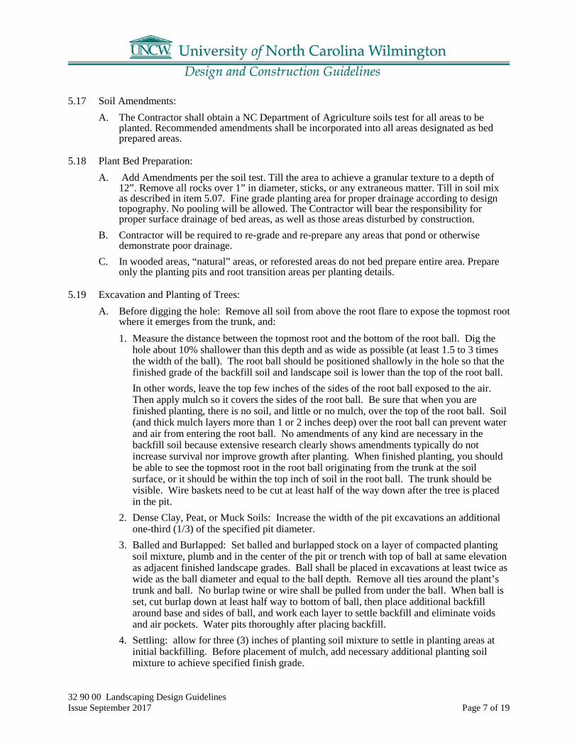
32 90 00 Landscaping Design Guidelines Issue September 2017 Page 7 of 19
5.17 Soil Amendments: A. The Contractor shall obtain a NC Department of Agriculture soils test for all areas to be
planted. Recommended amendments shall be incorporated into all areas designated as bed prepared areas.
5.18 Plant Bed Preparation: A. Add Amendments per the soil test. Till the area to achieve a granular texture to a depth of
12”. Remove all rocks over 1” in diameter, sticks, or any extraneous matter. Till in soil mix as described in item 5.07. Fine grade planting area for proper drainage according to design topography. No pooling will be allowed. The Contractor will bear the responsibility for proper surface drainage of bed areas, as well as those areas disturbed by construction.
B. Contractor will be required to re-grade and re-prepare any areas that pond or otherwise demonstrate poor drainage.
C. In wooded areas, “natural” areas, or reforested areas do not bed prepare entire area. Prepare only the planting pits and root transition areas per planting details.
5.19 Excavation and Planting of Trees: A. Before digging the hole: Remove all soil from above the root flare to expose the topmost root
where it emerges from the trunk, and: 1. Measure the distance between the topmost root and the bottom of the root ball. Dig the
hole about 10% shallower than this depth and as wide as possible (at least 1.5 to 3 times the width of the ball). The root ball should be positioned shallowly in the hole so that the finished grade of the backfill soil and landscape soil is lower than the top of the root ball. In other words, leave the top few inches of the sides of the root ball exposed to the air. Then apply mulch so it covers the sides of the root ball. Be sure that when you are finished planting, there is no soil, and little or no mulch, over the top of the root ball. Soil (and thick mulch layers more than 1 or 2 inches deep) over the root ball can prevent water and air from entering the root ball. No amendments of any kind are necessary in the backfill soil because extensive research clearly shows amendments typically do not increase survival nor improve growth after planting. When finished planting, you should be able to see the topmost root in the root ball originating from the trunk at the soil surface, or it should be within the top inch of soil in the root ball. The trunk should be visible. Wire baskets need to be cut at least half of the way down after the tree is placed in the pit.
2. Dense Clay, Peat, or Muck Soils: Increase the width of the pit excavations an additional one-third (1/3) of the specified pit diameter.
3. Balled and Burlapped: Set balled and burlapped stock on a layer of compacted planting soil mixture, plumb and in the center of the pit or trench with top of ball at same elevation as adjacent finished landscape grades. Ball shall be placed in excavations at least twice as wide as the ball diameter and equal to the ball depth. Remove all ties around the plant’s trunk and ball. No burlap twine or wire shall be pulled from under the ball. When ball is set, cut burlap down at least half way to bottom of ball, then place additional backfill around base and sides of ball, and work each layer to settle backfill and eliminate voids and air pockets. Water pits thoroughly after placing backfill.
4. Settling: allow for three (3) inches of planting soil mixture to settle in planting areas at initial backfilling. Before placement of mulch, add necessary additional planting soil mixture to achieve specified finish grade.

32 90 00 Landscaping Design Guidelines Issue September 2017 Page 8 of 19
5. Container Grown Stock: When using container grown stock, excavate as specified for balled and burlapped stock and adjusted excavations to size of container width and depth.
6. Saucers: The owner may decide that the use of saucers is not required in irrigated areas. 7. Anti-Desiccant: At the direction of the owner, deciduous trees or shrubs that are moved
when in full-leaf may be sprayed with anti-desiccant at nursery before moving and sprayed again two weeks after planting.
5.20 Mulch: A. Mulch pits, trenches, beds, and planted areas. Provide no more than a 4” inch thickness of
mulch around trees and shrubs and a three inch thickness of mulch around groundcovers, herbaceous materials and bulb beds, etc. Weed and turf suppression during establishment is essential. Apply a 4-inch thick layer of mulch around the plant to help discourage weeds. An area two feet in diameter for each inch of tree trunk diameter (minimum diameter should be eight feet for trees with a trunk diameter less than 3 inches) should be maintained during the establishment period. When mulching trees, apply a 4” layer over the outer half of the root ball. This keeps the trunk dry and allows rainwater, irrigation, and air to easily enter the root ball. Mulch resting on the trunk or layered too thick can kill the plant by starving it of oxygen, killing t he bark, causing the stem and root, preventing hardening off for winter, encouraging rodent damage to trunk, keeping soil too wet, and repelling water. Mulch on the root ball has little impact on water loss from the tree since most of the moisture that leaves the root ball does so by transpiration, not evaporation. Only a small amount (<10%) leaves the root ball by evaporation from the surface of the root ball. Preferred mulch is fresh long-leaf pine straw.
5.21 Staking: A. Trees shall be staked according to the planting detail in a plumb position immediately after
planting. Stakes shall be placed in undisturbed soil adjacent to tree planting pits and under no circumstance placed in tree pits. In many instances, if foot balls are heavy enough, stakes are not necessary. Stake to stabilize the root ball. Most field grown trees doe not need staking because their root balls are heavy enough to stabilize the tree in the ground. Some container grown trees will require staking in open areas since root balls are much lighter in weight.
B. Guy wires or other guying material shall be encased in hose to prevent direct contact with bark of the tree and shall be placed around the trunk in a single loop sized a minimum of three (3) times the caliper of the tree. Wires shall be tightened and kept taut by turnbuckles. Other guying materials shall also be regularly tightened and kept taut by the Contractor.
5.22 Pruning: A. If required and only after approval by the owner, each tree and shrub shall be pruned in
accordance with standard horticultural practice to preserve the natural character of the plant. Pruning shall be done with clean, sharp tools. The bruised or broken parts of large or fleshy roots shall be cut off smoothly before planting. All cuts on trees shall be made outside of the branch collar back to the main trunk or branch. Evergreen plants shall not be pruned except to remove dead or broken branches.
5.23 Watering: A. The Contractor shall provide water unless the plantings are irrigated. B. Containerized plants shall be watered immediately prior to planting. Thoroughly water plants
immediately after planting to thorough saturation of all backfill in the pits and beds during the same day of planting. When fully settled, the plants should be at the proper grades and vertical.

32 90 00 Landscaping Design Guidelines Issue September 2017 Page 9 of 19
C. Apply water only by open-end hose at low pressure. Sufficient water is achieved by filling root zone twice per application per tree and per shrub. Rain substitutes for a scheduled watering when at least two inches of rainfall has been verified. It is the responsibility of the Contractor to keep the plant root zone moist enough to establish healthy and attractive plant material.
D. Watering requirements during the initial shock period (first 30 days after planting) shall be every day for the first three days; every other day for ten days; twice per week for two weeks.
E. Watering requirements during the establishment period (warranty period), after the first 30 days shall be 1” of water per week for one year.
5.24 Inspections and Acceptance: A. Request for Inspections shall be made 7 days before the anticipated date of inspection.
5.25 Planting Shrubs, Ground Covers, Herbaceous Materials, Bulbs, Corms, Tubers, etc.: A. Space plants as indicated in the planting plan. Dig holes large enough to allow for spreading
of roots and backfill with planting soil. Work soil around roots to eliminate air pockets. Water plants thoroughly after planting, taking care not to cover crowns of plants with wet soil.
B. Plant bulbs, corms, tubers, etc. at a depth equal to three (3) times the width of the item being planted. Back-fill with plant mix/ if bulbs, corms, tubers, etc. are to be placed under other herbaceous materials, place other herbaceous materials first and then plant bulbs, etc.
Part 6: Design Guide – Lawns and Grasses
6.01 General: A. Scope of Work: Provide seedbed preparation, liming, fertilization, seeding, and mulching of
all newly graded finish earth surfaces, unless indicated otherwise, and all areas inside or outside the limits of construction that are distributed by the Contractor’s operation and all areas identified as “lawn” or “sod”. Seeded areas shall be hydro seeded, except small areas that are inaccessible to the hydro seeding equipment, which shall be drill seeded.
6.02 Submittals: A. Certificates of Conformance – Contractor shall furnish Certificates of Conformance from
manufactured or agencies for the following prior to application: Seed Fertilizer Lime Soil (Soil Testing Recommendation – NC Department of Agriculture)
6.03 Manufacturer’s Literature: A. Manufacturer’s Literature that includes physical characteristics, application and installation
instructions and recommendations for the following: Hydraulic Mulch Material AND Erosion Control Material
6.04 Delivery: A. Fertilizer and Lime – Deliver materials to the site in the original, unopened containers bearing
the manufacturer’s chemical analysis, name, trade name, trademark, and indication of conformance to state and federal laws. In lieu of containers, furnish fertilizer and lime in bulk with a certificate indicating the information described above with each delivery.
B. Seed – Deliver seed to the site in original sealed packages bearing the producer’s guaranteed analysis for percentages of mixtures, purity, germination, weed seed content, and inert

32 90 00 Landscaping Design Guidelines Issue September 2017 Page 10 of 19
material. Label in conformance with the USDA Federal Seed Act, any other statues, rules and regulations and applicable state seed laws. Wet, moldy, or otherwise damaged seed will be rejected.
6.05 Installation: A. Lawns / areas to be grassed shall be at finish grade prior to seeding, etc. and this grade shall
be maintained. B. Permanent grass type shall be as agreed upon by the Owner’s Landscape Services
Superintendent as to type and location. C. Grassed areas installation preferences within budget constraints are:
1. sod installation 2. sprigging 3. hydroseeding 4. seeding
D. A soils analysis shall be prepared by a testing agency approved by the Designer. The contractor shall provide all soils recommended by the analysis.
E. Fertilizer selection and application rate shall be as determined by soil analysis. Fertilizer shall be a commercial fertilizer delivered in unopened, original containers each bearing the manufacturer’s guaranteed analysis. Any fertilizer which becomes caked or otherwise damaged, shall not be accepted.
F. The care of the lawn shall be the responsibility of the contractor until the project is accepted. Lawn care shall include watering, feeding, and cutting consistent with general practice of care for the type of lawn.
G. The contractor shall guarantee a live stand of permanent grass consisting of 95% coverage minimum for seeded grass with no bare spots greater than one (1) square foot. Acceptance shall be made after the grass has been mowed at least once and shows sufficient stand and cover as specified.
H. The contractor shall fully maintain the lawn through the warranty period except for the mowing, fertilization and watering after acceptance. The Owner will be responsible for mowing and watering, but this will not void the warranty.
I. Every effort is to be made to schedule planting to ensure the greatest chance of survivability for the planting.
J. Storage and Handling: 1. Store lime, fertilizer, and seed in dry locations away from contaminants. Protect seed from
drying out. When handling materials, do not drop or dump from vehicles.
6.06 Products: A. Seed: Only state-certified seed of the latest season’s crop shall be used and it shall be free
from any noxious weed seed. B. Sod: Sod shall consist of Bermuda Type 419 “Tifway” or Centipede. The Owner shall make
choice at time of installation. C. Fertilizer: Commercial grade, free flowing, uniform in composition and bearing the
manufacturer’s guaranteed statement of analysis as recommended by the results of the required soil analysis.

32 90 00 Landscaping Design Guidelines Issue September 2017 Page 11 of 19
D. Mulch: Free from noxious weeds, mold, or other deleterious material. Provide wood cellulose fiber when hydro-seeding.
E. Straw – Straw shall consist of stalks from oats, wheat, rye, barley, or rice. Furnish straw of air-dry condition and of proper consistency for placement with commercial mulch-blowing equipment.
6.07 Execution: A. Preparation:
1. Seed Bed – Areas to be seeded shall be brought to the required sub-grade. New areas to be seeded shall be thoroughly tilled to a minimum depth of four (4) inches by scarifying, disking, harrowing, or other approved methods. Remove debris and stones larger than one (1) inch from all areas to be seeded.
2. Fertilizer and Lime – Apply fertilizer and lime at the rates described in this specification or as recommended by the required NC Department of Agriculture Soil Tests.
3. Drill Seeding – Incorporate fertilizer and lime into the soil to a minimum depth of four (4) inches. Application may be performed as part of the tillage operations.
4. Hydro-seeding – Apply liquid fertilizer in amounts recommended by NC Department of Agriculture Soil Tests. Apply lime manually.
6.08 Seeding Operations A. Seed Rates – Seed combinations are to be utilized at rates shown according to calendar dates
of seeding operations. B. Grades – Grades on the areas to be seeded that have been established previously shall be
maintained in a true and even condition. C. Disturbed Areas – In disturbed areas to be seeded, the Contractor will be responsible for
insuring that the soil present in these areas is friable and capable of sustaining a stand of grass acceptable to the Owner.
D. Soil Amendments – Before seeding operations, the soil shall be amended as follows: 1. Fertilizer shall be uniformly distributed at the rates recommended by the required NC
Department of Agriculture Soil Tests. 2. Lime shall be uniformly distributed at the rates described in this specification or as
recommended by the required NC Department of Agriculture Soil Tests. Amendments shall be incorporated into the soil by disking, harrowing, or other acceptable method.
E. Seeding Method – Seed shall be broadcast either by hand or approved sowing equipment. One half (1/2) of seed mix shall be distributed with the sower moving in one direction, and the remaining one half (1/2) shall be sown with the sower moving at right angles to the first sowing.
F. Seed Distribution – Seed distribution on the ground surface shall be covered to a depth not to exceed one half (1/2) inch by raking or other approved method.
G. Seed Compaction – Immediately after the seeding operations have been completed, the entire seeded area shall be compacted by means of a roller or other approved equipment.
H. Hydro-Seeding – Mix seed, fertilizer, and wood cellulose fiber in required amount of water to produce a homogeneous slurry. After seed, water, and fertilizer have been thoroughly mixed, add one thousand and five hundred (1,500) pounds of wood cellulose fiber per acre (dry weight) and apply the slurry. Seed shall not remain in agitated water containing fertilizer for more than one (1) hour before application.

32 90 00 Landscaping Design Guidelines Issue September 2017 Page 12 of 19
I. Mulching – Straw-mulch shall be spread uniformly in a continuous blanket using seventy-five (75) pounds per one thousand (1,000) square feet over the entire seeded area. After the straw-mulch has been applied, it will be tacked in place by a disc or other suitable equipment.
J. Watering – The mulched and seeded areas shall be sprinkled with water applied in a light spray until the seedbed is thoroughly moist to a depth of one (1) inch. Sprinkling shall be continued during dry weather to ensure a good stand of grass.
K. Initial Maintenance – The contractor shall be responsible for care of seeded areas while grass is becoming established. Mowing of the seeded areas shall be the responsibility of the Contractor within the establishment period with approved mowing equipment to a height of two (2) inches when average height of grass becomes three (3) inches. 1. Establishment Period – The establishment period shall be one (1) month or as required to
obtain a complete stand of mowable grass which is acceptable by the Owner.
6.09 Sodding Operations: A. General
1. Sod shall consist of Centipede Grass (Eremochloa ophiuroides). or Common Bermuda, (Cynbdon dactylon) of the variety described in this specification and shall be free of weeds and undesirable plants large stones or roots.
B. Grades 1. Grades on the areas to be sodded that have been established previously shall be
maintained in a true and even condition. C. Sodding Specifications
1. Sod shall be weed free, free of undesirable plants, large stones or roots. 2. Herbicide – Entire area to be sodded should be sprayed with the non-selective 41%
Glysophate product. 3. Waiting Period – Allow at least forty-eight (48) hours post – herbicide application before
tilling and grading begins. 4. Tilling and Grading – Area should be tilled to a depth of six to eight (6-8) inches and
raked to a true and even condition about one (1) inch below grade. 5. Placement – Sod shall be laid smoothly, edge-to-edge and with staggered joints. Sod shall
be pressed immediately into firm contact with the soil by tamping or rolling so as to eliminate all air pockets, provide a true and even surface and assure knitting without displacement of the sod or deformation of the surfaces of sodded areas
6. Rolling – Sod shall be mechanically rolled immediately to firmly contact the soil, eliminate all air pockets and provide a true and even surface to assure knitting, without displacement of the sod, or deforming the surface of the sodded areas.
7. Watering – After the sodding operation is complete, sufficient water shall be applied to wet the sod completely, and wet at least 2” of the soil below the sod.
8. Initial Maintenance - The Contractor shall be responsible for the care of the sodded areas while grass is becoming established. The establishment period should be one (1) month or as required to obtain a complete stand of mowable grass that is acceptable to the Owner. The Contractor shall mow sodded areas within establishment period with approved mowing equipment to the proper recommended height for the species.
32 90 00 Landscaping Design Guidelines Issue September 2017 Page 13 of 19
9. Establishment Period- The establishment period shall be one month with adequate average temperature for germination to occur or as required to obtain a complete stand of mowable grass which is acceptable to the owner.
6.10 Protection of Seeded and Sodded Areas: A. Immediately after seeding and sodding operations, protect the areas against traffic and other
uses by erecting barricades, as required, and by placing approved signs at appropriate intervals until final acceptance by the owner.
Part 7: Design Guideline – Tree Protection
7.01 Before work begins: A. Agreement will be reached with site manager and Campus Arborist on specific trees that will
be preserved. Communication between site manager, property owner, and Arborist is essential for success until project is completed.
7.02 Intent: A. Individual trees and/or groups of trees identified for protection during construction operations
shall be fenced and protected. For highly developed, high traffic campus sites and category 1 trees, a 5-foot high, chain link tree protection fence is required. For short construction periods of approximately three months or less, and for construction projects in less developed, low traffic areas metal poles with orange plastic barricade or wood tree protection fencing may be used. Every 50 linear feet of tree protection fence shall have a sign that says “ Tree Protection Area Do Not Enter” using 2” minimum height black letters on white background. At least one sign is required. This fencing may not be removed without the consent of the UNCW Project Manager and permission from the UNCW Construction Manager. Request for tree protection fence removal or any change from the contract documents regarding tree protection shall be made to Construction Management prior to any action. All trees to remain shall be watered 1” of water per week if rainfall does not meet 1” per week.
7.03 Tree Survey: A. All trees on campus construction and development sites shall be surveyed. Large wooded
areas or groups of trees shall be identified as a cluster on the survey. Major trees within these groupings, as determined by the Designer with the Campus Arborist, shall be numbered and surveyed according to size and type. Individual trees surveyed or key trees identified by the Designer or campus arborist shall be drawn to scale with the approximate canopy shown. Trees to be saved or removed shall be identified by the Designer and Campus Arborist and indicated on the site plans. As determined by the Designer, Campus Arborist, or UNCW Design Project Manager, trees outside the construction area at risk to construction damage also may be identified to remain and be protected.
7.04 Tree Protection Area: A. Establish the critical root zone of the trees to remain and identify this area on the plans. A
general rule for establishing the critical root zone is to measure and protect an area 1.5 times the canopy spread. Consult with the University Landscape Architect and Campus Arborist to define the critical root zone area and shape of the area to be protected during construction. Establish the limits to grading and tree protection fence to protect the largest amount possible of the critical root zone.
B. No materials, equipment, vehicles, or people may enter into the tree protection area. Allow no poisoning to trees with the dumping of materials such as solvents, gas, paint, and herbicides

32 90 00 Landscaping Design Guidelines Issue September 2017 Page 14 of 19
or with the washing of toxic materials into the tree protection area. Exercise care that no runoff from clean up operations (including concrete clean up wash water) enters the tree protection areas.
7.05 Tree Watering Plan: A. All trees to remain shall receive 1” water per week. Surface drip irrigation may be laid
throughout the root zone and covered with 2” composted chipped hardwood mulch.
7.06 Pruning: A. The contractor shall not remove or prune any landscape materials without prior consent from
the Owner. All tree work shall be by an Arborist certified by the International Society of Arboriculture, bonded, and insured. All work shall be according to standards set forth in the ANSI A300 publication Pruning Standards for Shade Trees, published by the National Arborist Association. Request for any tree or shrub pruning shall be directed to the Campus Arborist. Request for any tree removal shall be directed to the UNCW Construction Manager two weeks in advance. The UNCW Construction Manager will initiate a tree removal process with Grounds Maintenance. Any inadvertent injury to trees shall be cared for by a Certified Arborist and paid for by the contractor.
B. If plans require grading or digging in the critical root zone of protected trees, root prune the tree to avoid the ripping of roots with digging equipment. This may be accomplished with a trencher. Any roots larger than ½” that are damaged due to cut grading or trenching operations must be stubbed cleanly.
7.07 Disposal of Trees to be Removed: A. All debris from the pruning operation shall be disposed of lawfully off Campus.
7.08 Boring: A. Boring is required under major trees designated to remain to avoid root damage for utility
construction. This option is preferred, include direction to the contractor in the plans and specifications for location and size of boring pits and the direction and location of the bore.
7.09 Tree Preparation: A. Trees may be prepared for damage to the root zone in advance of construction. Evaluate with
the campus arborist the need for supplemental watering in the critical root zone to remain.
7.10 During Construction: A. In areas where construction vehicular and equipment traffic over tree roots is unavoidable,
place 12" of bark mulch or coarse wood chips as an organic base for traffic. In areas requiring repetitive construction traffic access place a layer of structural geo-textile fabric under the wood chips, and logging mats on top of the mulch and cover with additional layer of wood chip mulch. Chipped wood may be used for a temporary pedestrian path over root zones. 1. When excavating avoid cutting roots larger than 2”. When this is not possible, shovel by
and saw the root. Accidentally broken or crushed roots must be cut cleanly between the wound and the trunk to prevent decay.
2. Raising the grade more than 6” around a tree to be preserved will require retaining wall beyond the existing drip line.
3. If grade must be lowered, terracing as far from the tree trunk as possible will be required to preserve as many roots as possible. This can be done in steps for a more natural grade.

32 90 00 Landscaping Design Guidelines Issue September 2017 Page 15 of 19
When the grade must be lowered completely, construction of an island at the drip line will be required.
4. A heavy plastic tarp must be spread in concrete mixing areas and areas where sheetrock will be cut. The alkalinity of these materials can change soil Ph.
5. Paint brushes and tools will not be cleaned over tree roots. 6. Chemical wastes (paint thinner, etc.) will be disposed of properly and drained off site. 7. Even when barriers are erected, accidental breaks and scrapes may occur. Watch for
damage and report t his to Landscape Services promptly. Do not attempt pruning or repair work. Campus Arborist will determine best methods as they relate to the extent of injury.
7.11 Trenching: A. When trenching near trees, use ISA standards. In areas where trenching or digging is allowed
near trees to remain, store earth outside the critical root zone on the side of the trench away from the tree trunk to minimize compaction. If large tree roots are encountered, hand dig around the root and allow it to span the trench. During mechanical backfilling operations, use a tarp or plywood to prevent backhoe or dozer blade from cutting into the soil surface. The remaining clean up shall be by hand.
B. Refill open trenches as soon as possible. Root death can occur in 10 minutes if unfavorable weather conditions occur. Exposed roots in open trenches must be kept moist with a hose or sprinkler.
7.12 Clean up: A. All clean up operations shall avoid any disturbance to the original grades and surface soil in
the tree protection area. Clean up in tree protection areas may be accomplished only by hand raking.
7.13 Documentation by the Designer: A. Tree Protection Plan:
1. A separate tree protection plan sheet shall be required if tree protection involves more than a simple tree protection fence. When digging, planting, trenching, boring, watering, driving in the critical root zones, or other special root zone protection is required, a separate Tree Protection Plan describing procedures is necessary. (See Specification for Tree Protection on Construction Sites – Karen Tobiassen C.A.)
2. Actual, tree protection fence locations shall be shown to scale on all site plans as well as described in the specifications. Trees to be saved or removed shall be labeled as such on all site layout drawings as well as being shown on the demolition plan and grading plans. This includes electrical, plumbing, planting, etc.
7.14 Grades of Protected Trees: A. If grade must be lowered, terracing as far from the tree trunk as possible will be required to
preserve as many roots as possible. This will be done in steps for a more natural grade. When the grade must be lowered completely, construction on an island at the dripline will be required.
B. Raising the grade more than 6” around a tree to be preserved will require a retaining wall beyond the existing dripline. 1. Specifications must incorporate pertinent materials and methods used to protect trees.

32 90 00 Landscaping Design Guidelines Issue September 2017 Page 16 of 19
7.15 Penalties: A. Specifications must describe that the Designer or the UNCW Construction Manager may
issue a stop work order if any portion of the tree protection fence or methods are violated. This order remains effective until the protection is reinstated according to the contract documents with no penalty to the owner.
Part 8: Design Guideline – Irrigation
8.01 Design Criteria: A. Permanent irrigation systems shall be included for all plantings used as a part of the
landscaping. The irrigation system shall be designed as part of the project, and the Designer shall provide construction phase working drawings for this work.
B. Turfgrass and mulched bed and tree rings shall be on separate zones. C. Sleeves are required under all paved areas and should be 2” larger than the pipe specified. D. Irrigation will be designed to be installed prior to the installation of sidewalks. All sleeves
under paved areas shall be marked. E. Irrigation lines installed underground are to have wire tracer lines installed above the lines. F. All irrigation systems shall be designed according to UNCW guidelines. Design-Build
irrigation systems will not be accepted at UNCW. No irrigation shop drawing will be approved without an accurate irrigation site plan with the irrigation design that is in accordance with all the design guidelines. All irrigation shop drawings shall be reviewed and approved by the Designer and by Grounds Management prior to installation.
G. UNCW has a preference for the “Hunter” brand irrigation system components.
8.02 The Designer is responsible for: A. Developing the scope of irrigation for turf and planting areas with Grounds Management. B. Determining the water supply location and detailed description of the contractor’s work for
providing water supply to the irrigation site, including the location of the controller and a calibrated water meter; and water meter supply gravel for drainage.
C. Determining the electrical supply location and source for the controller and if an electrical meter is required;
D. measuring, researching, or ordering survey information for campus utilities, trees over 3.5” caliper, and delineation of turf and mulch locations;
E. ensuring all city and state plumbing code requirements are met and specifying pressure requirements of main and lateral lines;
F. separate irrigation zones for turf; G. separate irrigation zones for trees and shrubs; H. providing actual locations of heads on plans; I. pre-qualifying bidders with 3 years or more experience installing irrigation systems of
comparable scope; J. design of an above ground Reduced Pressure Back Flow Device (RPZ) with cover; K. including site repair and seeding schedule in the specifications; L. providing as-built drawings, due at final inspection.

32 90 00 Landscaping Design Guidelines Issue September 2017 Page 17 of 19
8.03 Irrigation Materials and Methods A. Back Flow:
1. The RPZ will be on copper or brass risers 1 inch or larger. The base of the risers at ground level will have unions for winter removal. Provide heat tape.
2. The RPZ will be mounted at least 12 inches but no more than 30 inches from the relief valve to the ground.
3. A brass ball valve and box will be installed 2 feet from the supply to the back flow for quick shutdown. Also, ball valve on incoming supply line backflow. No gate valves are used on UNCW irrigation systems.
4. The RPZ will be tested and a certified report sent to UNCW Construction Manager. B. Hot Box:
1. All RPZ will have a hotbox enclosure. Preferred color is Dark Green. Hot box to be bolted down, not to be unsecure.
C. Controller: 1. The controller shall have multiple start times and programs. Controller is to be hard
wired and sealed in a locked utility box. D. Valves:
1. Valves shall be electrically controlled automatic control systems diaphragm actuated and hydraulically operated solenoid valves. All Valves and wire splices will be in a 1- inch round valve box. Flow control and needle valves required.
E. Mainline: 1. Mainline shall be sized to requirements and shall be a minimum of 24” below finish grade.
F. Lateral Line: 1. Lateral lines shall be 1-inch minimum and at least 12 inches below finish grade wired for
location (no tape). G. Sleeves:
1. All sleeves are required under roads and walkways and shall be of Schedule 40 PVC and a maximum depth of 24 inches. No multi-strand wiring.
H. Drip Irrigation: 1. Trees and shrubs in grated pits only.
I. Spray Heads: 1. Six inch spray heads with check valves will be used for rotor turf irrigation. 2. All large turf areas will have a gear driven rotor sized for the area. 3. Twelve-inch spray heads will be used for annual and perennial beds.

32 90 00 Landscaping Design Guidelines Issue September 2017 Page 18 of 19
J. Quick Couplers: 1. All quick couplers will be installed on swing joints and secured with ground anchors,
surrounded with gravel in a 10-inch box. K. Trenching and Backfilling:
1. All trenching will be 6 inches wide minimum. Hand trenching is required to prevent root damage to trees. All backfill will be tamped and disturbed area reseeded or mulched. UNCW Landscaping Services to inspect irrigation before trenches are back filled.
Part 9: Other Landscaping Standards
9.01 Site Furnishings: See Section 12 93 00 Site Furnishings
9.02 Seating Walls: See Section 32 00 00 Exterior Improvements
9.03 Screen Walls: See Section 32 00 00 Exterior Improvements
9.04 Paving and Surfacing: See Section 32 00 00 Exterior Improvements
9.05 Parking Lots: Section 32 00 00 Exterior Improvements
Part 10: Maintenance
10.01 General: A. The Contractor is responsible for any and all maintenance activities required until final
acceptance of the planted areas by the Owner. Upon completion of the landscape plan installation and final acceptance of the project by the Owner, maintenance activities as described in the maintenance instructions supplied by the Contractor shall become the responsibility of the Owner. Any necessary plant replacement occurring during the warranty period remains the responsibility of the Contractor as described in the Warranty Section of the contract.
10.02 Watering: A. It shall be the Contractor’s responsibility to water all plants during and immediately after
planting and a minimum of once a week unless unusual wet weather or soil conditions exist or an irrigation system is in operation until final acceptance of the project by the Owner. At each watering the soil around each plant shall be thoroughly saturated. The equivalent of one (1) acre-inch of water minimum shall be applied per week minus any measurable rainfall occurring during that week.
10.03 Plant Material Care: A. Until final acceptance of the project by the Owner, maintain trees, shrubs, and other plants by
weeding as required for healthy growth. Tighten and repair stake and guy supports and reset trees and shrubs to proper grades or vertical position as required. Restore or replace damaged wrappings. Spray as required keeping trees and shrubs free of insects and disease.

32 90 00 Landscaping Design Guidelines Issue September 2017 Page 19 of 19
10.04 Tree Wrap, Stake and Guy Wire Removal: A. Tree wrap, stakes, guy wires and other guying materials may or may not be removed by the
Contractor at the conclusion of the one (1) year guarantee period at the discretion of the Owner.
Part 11: Clean-up and Protection
11.01 During landscape work, keep pavements and sidewalks clean and work area in an orderly condition. During and at the conclusion of landscape work, remove tire marks and other stains or discolorations resulting fro the landscape work from paved surfaces.
11.02 Protect landscape work and materials from damage due to landscape operations, operations by other contractors and subcontractors. Maintain protection during installation and maintenance periods until date of acceptance by the Owner.
11.03 All pavement, grassed and planted areas, structures and sub-structures disturbed due to the execution of this work shall be restored to their original conditions. Rework any eroded landscape areas resulting from the completion of this work.
11.04 During the course of planting, the site shall be kept clean. Excess and waste materials shall be continuously and promptly removed. Lawn areas are to be kept clear and all reasonable precautions taken to avoid damage to existing structures, plants and grass.
Part 12: Inspection and Acceptance
12.01 When landscape work is completed, including any required maintenance, the Owner will make an inspection to determine acceptability.
12.02 When inspected landscape work does not comply with requirements, replace rejected work and continue specified maintenance until re-inspection occurs by the Owner and the project is found to be acceptable. Remove any rejected plants and materials promptly from the project site.