Embed Size (px)
Citation preview

8/2/2019 Design Guide for Condrete Filled Hollow Section Columns Under Static Ans Sesmic Loading 5
http://slidepdf.com/reader/full/design-guide-for-condrete-filled-hollow-section-columns-under-static-ans-sesmic 1/70

8/2/2019 Design Guide for Condrete Filled Hollow Section Columns Under Static Ans Sesmic Loading 5
http://slidepdf.com/reader/full/design-guide-for-condrete-filled-hollow-section-columns-under-static-ans-sesmic 2/70

8/2/2019 Design Guide for Condrete Filled Hollow Section Columns Under Static Ans Sesmic Loading 5
http://slidepdf.com/reader/full/design-guide-for-condrete-filled-hollow-section-columns-under-static-ans-sesmic 3/70
I8J CONSTRUCTIONI WITH HOLLOW STEEL
SECTIONS
Edited by: Comite International pour Ie Developpement et l'Etude
de la Construction TubulaireAuthors: Bergmann, Reinhard, Ruhr-University of Bochum, Germany
Matsui, Chiaki, Kyushu University, Fukuoka, JapanMeinsma, Christoph, Ruhr-University of Bochum, Germany
Dutta, Dipak, Technical Commission of Cidect

8/2/2019 Design Guide for Condrete Filled Hollow Section Columns Under Static Ans Sesmic Loading 5
http://slidepdf.com/reader/full/design-guide-for-condrete-filled-hollow-section-columns-under-static-ans-sesmic 4/70
PU.
eeUd
9GOWG1
B0M0~N
~
i

8/2/2019 Design Guide for Condrete Filled Hollow Section Columns Under Static Ans Sesmic Loading 5
http://slidepdf.com/reader/full/design-guide-for-condrete-filled-hollow-section-columns-under-static-ans-sesmic 5/70

8/2/2019 Design Guide for Condrete Filled Hollow Section Columns Under Static Ans Sesmic Loading 5
http://slidepdf.com/reader/full/design-guide-for-condrete-filled-hollow-section-columns-under-static-ans-sesmic 6/70
(eedeOeS
6weS°oe
(Sqe°oeS
(Sqe:eSuwuon
(SqeoOAeS
(Sqe6eSuwuon
:LSSqM
'eSoMSo
'u~eneS
eMs°oeOSSeX
e6eMeee
sOes°OeWMe
oeo6eS6SO
.°o°oMOPnne~sS
eeeSOene
pSeeOeeUe
euOeSXMG
LnSe
pSUUUedOeUSq
sMS°O
JeWeSe
"qeS
UewAeSUqpe6uMqe
'eU
uOeSSnw
u°oeuOu
LM°oOSSe
"enMS
AqPuOeO
"eeJOUeOoOe
.eleeueo
's°!OeXeUA6UOS
JSSusMe
sueeeqSAuqSASeS
.OuSse
6nM6°eSeL6S
6P6SOeSe
:MeSdeSe
oeeOeuAeU
UgdesPeS
AsPeM
'suWeSeOSUee
LMOeSeeeeSO°
aa

8/2/2019 Design Guide for Condrete Filled Hollow Section Columns Under Static Ans Sesmic Loading 5
http://slidepdf.com/reader/full/design-guide-for-condrete-filled-hollow-section-columns-under-static-ans-sesmic 7/70
-Design guide for circular and rectangular hollow section joints under fatigue loading (in
preparation)
By means of these design guides CIDECT likes to inform and enlighten the architects,
constructors and designers as well as the professors and students of the technical
universities and engineering schools about the latest developments of design and
construction with hollow sections.
We are thankful to the two well known experts in the field of composite structures -
Dr. Reinhard Bergmann, Ruhr-University Bochum, Germany, and Prof. Chiaki Matsui,
Kyushu University, Fukuoka, Japan, -whose collaboration made this design guide possible.
Further, we acknowledge gratefully the support of the CIDECT member firms.
Dipak Dutta
Technical Commission
CIDECT

8/2/2019 Design Guide for Condrete Filled Hollow Section Columns Under Static Ans Sesmic Loading 5
http://slidepdf.com/reader/full/design-guide-for-condrete-filled-hollow-section-columns-under-static-ans-sesmic 8/70
9
JnaawB
v
8PMMon8
LuMUMOnp
Ld
9
vPwa
£e
~°e
~°eedg
~e
~qB
LUOD
gOeOV
geWPev
gPpS
vOeWeedS
~eWee£
~ve6£
~uOeWOde
LeXU
LJeSS£
gOeSO£
9uOSS£
£DO
6e£
9eUOSS£
9e£
9e
9dS
GeeeG
GeeG
GP
6eS
6e
6
e
s

8/2/2019 Design Guide for Condrete Filled Hollow Section Columns Under Static Ans Sesmic Loading 5
http://slidepdf.com/reader/full/design-guide-for-condrete-filled-hollow-section-columns-under-static-ans-sesmic 9/70Concrete filling procedure of structural hollow section columns on site.

8/2/2019 Design Guide for Condrete Filled Hollow Section Columns Under Static Ans Sesmic Loading 5
http://slidepdf.com/reader/full/design-guide-for-condrete-filled-hollow-section-columns-under-static-ans-sesmic 10/70
!OU~JOOn
"eWeMee~eq
eSoeSev'ee~eu~
ASSuepu
4oSSOUDewneeO~UpuUe~
M0neO~eu~eOeOpeeSOApeOeSeS
lWeeoOUSe
°~oeeJUS~epeSeOeSneJUDeDS
lUeSqeeUeeUpSeJoe~
!OdO%OAUwv°oOD~eDO
eeSUSwseUeseSSuSeOeeeUSe
.u~Ae0eeWe~
!OeeOseSu
"ueeOSDSeeOepeSSXM
eqeOJSDpeSeLSes~e°SSSeqe
pe0sSeeSMO
pUSeeeSee
enoOSS
SoOSMue
SUueoeSe
seS
"eOsUsmSUnOueeeene~
M0eSDGOJ.
OoeSSDOUpqAeoJ.SeuD
e~0eMoOPe>4e
.4DSeeedoeeeee
.oO0Ao~MeepeO~v
'eSSSeOenoeOeJDUODeee~S
leOMOp~S~oe
e~osoO4oOu
eUoeeOeo
r
U

8/2/2019 Design Guide for Condrete Filled Hollow Section Columns Under Static Ans Sesmic Loading 5
http://slidepdf.com/reader/full/design-guide-for-condrete-filled-hollow-section-columns-under-static-ans-sesmic 11/70
simplification as EC4. As the Australian design method for steel structures uses different
Column Curves than the European ones, it might be that these curves will also be the basis
for the design of composite columns. Fig. 2 shows the comparison of the Australian buckling
curve for hollow sections according to [12] with the European buckling curve a, which has to
be taken for hollow sections, concrete filled or unfilled. The Australian design rules for
composite columns are expected to be completed and published at the end of 1995.
:~ 7:': :. ::.:'.:.-:~::.. 0 .- : :: :
..:: : :::.: ,. :. .;
:' .; :~., .::.'.-:.;
Fig. 1 -Composite steel and concrete sections covered by [7].
X=Nc,;Npl
1.0AS100-1990
0.5
0.0
1.50 3.00 "");.
Fig. 2 -Comparison of the Australian and the European column curve "a".

8/2/2019 Design Guide for Condrete Filled Hollow Section Columns Under Static Ans Sesmic Loading 5
http://slidepdf.com/reader/full/design-guide-for-condrete-filled-hollow-section-columns-under-static-ans-sesmic 12/70
"e
SnMe
"OOd
eMdnUUS
MnJnM°n
eOOeS
"On
u
SOwO
oeO°
u~nvpeepe°w
e°OWn
uO
~Oee
ee°eO

8/2/2019 Design Guide for Condrete Filled Hollow Section Columns Under Static Ans Sesmic Loading 5
http://slidepdf.com/reader/full/design-guide-for-condrete-filled-hollow-section-columns-under-static-ans-sesmic 13/70
2 Design method according to Eurocode 4
2.1 General design method
The design of composite columns has to be carried out for the ultimate limit state. Under the
most unfavourable combination of actions, the design has to show that the resistance of the
section is not exceeded and that overall stability is ensured.
The analysis of the load bearing capacity shall include imperfections, the influence of
deflections on the equilibrium (second order theory) and the loss of stiffness if parts of the
section become plastic (partially plastic regions). For concrete, the stress-strain relationship
shall follow a parabolic rectangular curve, whereas for structural and reinforcing steel, a
bilinear curve is valid.
An exact calculation of the ultimate load of a composite column following all these
requirements can only be carried out by means of a computer program (FEM) [6] and is not
economical for the practical engineer. Therefore those computer programs should be used in
addition to tests to develop a simplified design method.
The design has to fulfil eqn. 1, where Sd is the combination of actions including the load
factors "fF and Rd is the combination of the resistances depending on the different partial
safety factors for the materials "fM.
( f f f )~ R = R --L ..::!:o ..!'!: (1 )d "\I' "\I ' "\I, 'Ma 'c 's
Eurocode 3 uses an additional system safety factor in order to cover failure by stability
reason, which is applied to the complete resistance side of eqn. 1. For composite columns
this additional safety factor is only applied to the steel part of the section ("fMa). So for
composite columns which are endangered to fail by buckling, the steel strength has to be
divided by "fMa' alternatively by "fa according to table 1. The system factor "fMa may be takenhigher than "fa. Danger of stability failure may be considered as excluded if the columns are
compact, that means the relative slenderness ):: doe~ not exceed 0.2, or if the design normal
force is very small, i. e. not greater than 0.1 Ncr (for A and Ncr' see chapter 3.4).
The safety factors in the current edition of Eurocode 4 [4] are boxed values, which expresses
that these values are recommended values which could be changed by national application
documents. The recommendation for "fMa s the same as for "fa (table 1).
Table 1 -Partial safety factors for resistances and material properties for fundamental
combinations.
structural steel concrete reinforcement
"fa = 1.1 1c = 1.5 " 16 = 1.15 ,-'
The safety factors for the actions "fF have to be chosen according to Eurocode 1 or national
codes respectively. These values as well as the material factors for other than normal
conditions are not treated here. If the material factors given in table 1 are modified, they are
described in the relevant following clauses.
2.2 Material properties
For composite columns the materials may be used, which are included in Eurocode 2
(concrete structures) and Eurocode 3 (steel structures) respectively. Detailed informations
about the material properties are given in these codes.
12

8/2/2019 Design Guide for Condrete Filled Hollow Section Columns Under Static Ans Sesmic Loading 5
http://slidepdf.com/reader/full/design-guide-for-condrete-filled-hollow-section-columns-under-static-ans-sesmic 14/70'SSSeU8UUU
[WN
fSeOsnu 0
[N
45SA 0
q>A>
88Os~6S 0LOO
aeAanAaq
'SSepgOO
.UgSnMOn6sS
eMee6Sq

8/2/2019 Design Guide for Condrete Filled Hollow Section Columns Under Static Ans Sesmic Loading 5
http://slidepdf.com/reader/full/design-guide-for-condrete-filled-hollow-section-columns-under-static-ans-sesmic 15/70
In order to consider the influence of long time acting loads (not creep and shrinkage), the
concrete strength is reduced by the factor 0.85. For composite columns with concrete filled
hollow sections, this value need not be taken into account, because a more favourable
development of concrete strength is achieved in the steel tube and because peeling off of the
concrete is impossible. In the following text this factor will not be mentioned any more. Theinfluence of creep and shrinkage on the load bearing capacity has only to be considered if
significant. This will be treated in the simplified design method given in chapter 3.
For the reinforcing steel, the regulations of Eurocode 2 are valid. Most of the reinforcing steel
grades are characterized by their names, e.g. the name gives the value of the nominal
strength. A very common reinforcing steel is the grade 8500 with a nominal strength of
500 N/mm2. In Eurocode 2 the modulus of elasticity for the reinforcement is given byEs = 200 000 N/mm2. For the sake of simple calculation, the same modulus of elasticity for
the reinforcing steel may be taken as for structural steel in composite construction: Es = Ea
= 210 000 N/mm2.
For the structural steel of composite sections, the common steel grades are given in table 3.The sections may be hot rolled or cold formed. The values of table 3 are valid for material
thicknesses not higher than 40 mm. For material thicknesses between 40 mm and 100 mm
the strengths have to be reduced. High strength steel may be used, if the relevant
requirements for the ductility are observed as given in Eurocode 3 [13].
Table 3 -Nominal (characteristic) values of yield strengths and modulus of elasticity forstructural steel
steel grades Fe235 Fe275 Fe355 Fe460
yield s'trength fy [N/mm2] 235 275 355 460
modulus of elasticity Ea [N/mm2] 210 000
For structural steel and for reinforcing steel the nominal strength may be taken as the
characteristic strength. The design strengths of the materials are obtained by using the partial
safety factors given in table 1.
fcd = fck / Yc for concrete (2)
fsd = fsk / Ys for reinforcement (3)
fyd = fy / YMa for structural steel (4)

8/2/2019 Design Guide for Condrete Filled Hollow Section Columns Under Static Ans Sesmic Loading 5
http://slidepdf.com/reader/full/design-guide-for-condrete-filled-hollow-section-columns-under-static-ans-sesmic 16/70
(£Wo
9Won
0~e
PBOMBUSPBW
.NM
I(N
.SWA
(P(5onp
(
(OUO(on
.aWMOMU
OOWae
UOMqU
aOeeeOWn
5e
.SMMO8
zr.
:° -
p
'Sne
eeMpe
.AeOna
UO£O
eWOdue
UpaedaO
UUOw
UO
pee
JqdsOd
ae"
padS

8/2/2019 Design Guide for Condrete Filled Hollow Section Columns Under Static Ans Sesmic Loading 5
http://slidepdf.com/reader/full/design-guide-for-condrete-filled-hollow-section-columns-under-static-ans-sesmic 17/70
For the structural steel grades given in table 3, the limit values for dlt or hit are shown in
table 4. These values consider that the buckling of the walls of concrete filled sections is only
possible in the outer direction. Compared with pure steel sections [5], a better behaviour
concerning buckling can be achieved. The limits shown in table 4 are found on the basis of
classifying the concrete filled sections in the class 2. The classification in class 2 means that
the internal forces are determined by following elastic analysis and are compared to theplastic resistance of the section. Class 2 sections are assumed to have limited rotation
capacity, so that plastic analysis is not allowed, which takes moment redistribution by plastic
hinges into account. Detailed information is given in [5].
3.3 Resistance of a section to axial loads
The plastic resistance of the cross section of a composite column is given by the sum of the
components:
Npl.Rd = Aa fyd + Ac fcd + As fsd (8)
where
Aa, Ac and As are the cross sectional areas of the structural steel, the concrete and the
reinforcement,
fyd' fcd and fSd are the design strengths of the materials mentioned above.
Fig. 4 shows the stress distribution, on which eqn. 8 is based.
fcd fyd fsd
Fig. 4 -Stress distribution for the plastic resistance of a section
The ratio of reinforcement is limited to p = 4% of the concrete section. More reinforcement
may be necessary for the design against fire, but shall not be taken into account for the
design using the simplified method of Eurocode 4. No minimum reinforcement is necessary
for concrete filled sections; but if reinforcement shall participate in the load bearing capacity,
the minimum amount of reinforcement has to be p = 0.3%.
As a proportion of Npl.Rd the cross section parameter 0 may be determined:
A f0 = -!!:-J.!}. (9)
NpI,Rd
Here NpI,Rd and fYd are to be determined taking "fMa = "fa'
This value has to fulfil the following requirement:
0.2$0$0.9 (10)
This check defines the composite column. If the parameter 0 is less than 0.2, the column shall
be designed following Eurocode 2 [14]; on the other hand when 0 is greater than 0.9, the
column shall be designed as a steel column according to Eurocode 3 [13].

8/2/2019 Design Guide for Condrete Filled Hollow Section Columns Under Static Ans Sesmic Loading 5
http://slidepdf.com/reader/full/design-guide-for-condrete-filled-hollow-section-columns-under-static-ans-sesmic 18/70
(5JO
(O1B1
:eMO1p
O1SeSMPO
(O1=
e
(O1
seO8
'uOnO~S
eM
(+Pd
:JeMM~u
5wqeonO
Sn66SS1O
1
e1
c
e1~
.eu
ennee
eMseSO
eS5u
SOOn

8/2/2019 Design Guide for Condrete Filled Hollow Section Columns Under Static Ans Sesmic Loading 5
http://slidepdf.com/reader/full/design-guide-for-condrete-filled-hollow-section-columns-under-static-ans-sesmic 19/70
Concrete filling of circular hollow section columns. For uniform concrete filling, the columns are heldinclined.

8/2/2019 Design Guide for Condrete Filled Hollow Section Columns Under Static Ans Sesmic Loading 5
http://slidepdf.com/reader/full/design-guide-for-condrete-filled-hollow-section-columns-under-static-ans-sesmic 20/70
"~~~
p~8seS~OSSd
e
(d
'JOSSeOeee~OO
'seSO
AWeeS~~v
6~eOSSO
seXOSSe
'pqU9O
ueeuOOeUUUOl~enenAOSeMSeu
esUe~N
!O6SAMueUene
eu~Uene~P
PeOee~eS6SeeOe
u9qUueeO~sOUed
'8uMWeneS
ese~uS~ene
Sp04HdSSOu
pWeo11e~e
ee
pS~OuX
e
P (X
V
:Au
'pde0geeeOP
eeUeOUn0Pe
pOeOUUgOO
eeeO~UUO~
O0oO
OO
9OO"
SOn
peUBSq
"OeU1p1eq
8/2/2019 Design Guide for Condrete Filled Hollow Section Columns Under Static Ans Sesmic Loading 5
http://slidepdf.com/reader/full/design-guide-for-condrete-filled-hollow-section-columns-under-static-ans-sesmic 21/70
Table 6 -Increase in !.esistance to axial loads for different ratios of d/t, fyifck and selected values
for e/d and A due to confinement.
d/t = 40 d/t = 60 c' d/t = 80
f/fck f.;tCk f.;tck:'):; e/d 5 10 15 5 10 15 5 10 15
0.0 0.00 1.152 1.238 1.294 1.114 1.190 1.244 1.090 1,157 1.2070.01 1.1371.2151.2641.1021.171 1.2201.081 1;141 1.1860.02 1.1221.1911.2351.0911.1521.1951.0721.1251.1660.03 1.1071.1671.2061.0801.133 1.171 1.0631.1101.145t 0.04 1.0911.1431.1761.0681.1141.1461.0541.0941.124
.0.05 1.076 1.119 1.147 1.057 1.095 1.122 1.045 1.078 1.103! 0.06 1.061 1.095 1.118 1.045 1.076 1.098 1.036 1.063 1.083
0.07 1.046 1.072 1.088 1.034 1.057 1.073 1.027 1.047 1.0620.08 1.030 1.048 1.059 1.023 1.038 1.049 1.018 1.031 1.0410.09 1.015 1.024 1.029 1.011 1.019 1.024 1.009 1.016 1.021
0.2 0.00 1.048 1.075 1.093 1.036 1.060 1.078 1.029 1.050 1.0660.01 1.043 1.068 1.083 1.033 1.054 1.070 1.026 1.045 1.0600.02 1.038 1.060 1.074 1.029 1.048 1.062 1.023 1.040 1.0530.03 1.034 1.053 1.065 1.025 1.042 1;054 1.020 1.035 1.0460.04 1.029 1.045 1.056 1.022 1.036 1.047 1.017 1.030 1.0400.05 1.024 1.038 1.046 1.018 1.030 1.039 1.014 1.025 1.0330.06 1.019 1.030 1.037 1.014 1.024 1.031 1.012 1.020 1.026
0.07 1.014 1.023 1.028 1.011 1.018 1.023 1.009 1.015 1.0200.08 1.0101.0151.0191.0071.0121.0161.0061.0101.013
.0.09 1.005 1.008 1.009 1.004 1.006 1.008 1.003 1.005 1.007
0.4 0.00 1.005 1.008 1.010 1.004 1.007 1.009 1.003 1.006 1.008~
-0.01 1.005 1.007 1.009 1.004 1.006 1.008 1.003 1.005 1.0070.02 1.004 1.006 1.008 1.003 1.005 1.007 1.003 1.005 1.0060.03 1.004 1.006 1.007 1.003 1.005 1.006 1.002 1.004 1.0050.04 1.003 1.005 1.006 1.002 1.004 1.005 1.002 1.003 1.0050.05 1.003 1.004 1.005 1.002 1.003 1.004 1.002 1.003 1.004
0.06 1.002 1.003 1.004 1.002 1.003 1.003 1.001 1.002 1.0030.07 1.002 1.002 1.003 1.001 1.002 1.003 1.001 1.002 1.0020.08 1.001 1.002 1.002 1.001 1.001 1.002 1.001 1.001 1.0020.09 1.001 1.001 1.001 1.000 1.001 1.001 1.000 1.001 1.001
The values of X may be determined analytically by means of eqn. 18 or by an interpolationbased on table 7.
1X = I_" ;-" (18)
«1»+ ;<I>2-A2
with
<I>= 0.5 [ 1 + 0.21l i -0.2) + i2J (19)
The relative slenderness I is obtained by:
i = ~ (20)~~

8/2/2019 Design Guide for Condrete Filled Hollow Section Columns Under Static Ans Sesmic Loading 5
http://slidepdf.com/reader/full/design-guide-for-condrete-filled-hollow-section-columns-under-static-ans-sesmic 22/70
p
lUUeSESOn
'AeuU
eSMe
eeEeOESeOO1
eM
(GO
:ueOOOSSo1
9O~OO~OO~OOO9OOOOOO
LOOOOO~
£OOOOOO
£0OOOOo~LO~OOOOO~
LOOOOO~
£OOOOOOOO
9OOO~
9OO
£OO0
j £OOOOOOO
OOO0OOOOO
~OOOOOOOOOO
~0OOOOOvOO~0
LO0O0O
9O00O
OO0O
O~
0
6OOO0OO0
,XJuq
"OE15E5°
es°OnMOn
USeWeu°O5e1
"Oe
p°O5
eM
c (3
'EnOep~M
pdSEXOSSd
eM

8/2/2019 Design Guide for Condrete Filled Hollow Section Columns Under Static Ans Sesmic Loading 5
http://slidepdf.com/reader/full/design-guide-for-condrete-filled-hollow-section-columns-under-static-ans-sesmic 23/70
0.8 Ecd Ic is the effective stiffness of the concrete section with
Ecd = Ecm / 1.35 (23)
with Ecm being the secant-modulus of concrete according to table 2.
The reduction of the concrete component in eqn. 22 by the factor 0.8 is a measurement to
consider cracking in the concrete caused by moment action due to second order effects. The
stiffness has to be determined using a safety factor of 1.35 (eqn. 23).
The simplified design method of Eurocode 4 has been developed with an effective stiffness
modulus of the concrete of 600 fck. In order to have a similar basis like EC2, the secant
modulus of concrete Ecm was chosen as reference value. The transformation led to the factor
0.8 in eqn. 22. This factor as well as the safety factor 1.35 in eqn. 23 may be considered as
the effect of cracking of concrete under moment action due to the second order effects. So, if
this method is used for a test evaluation of composite columns, which is typically done
without any safety factor, the safety factor for the stiffness should be taken into account
subsequently, i.e. the predicted member capacity should be calculated using (0.8 Ecm /1.35).
In addition, the value of 1.35 should not be changed, even if different safety factors are used
in the country of application.
The influence of the long-term behaviour of the concrete on the load bearing capacity of the
column is considered by a modification of the concrete modulus. Caused by the influence of
the deflections on the internal forces (second order theory) the load bearing capacity of the
columns may be reduced by creep and shrinkage. For a loading which is fully permanent, the
modulus of the concrete is half of the origin value. For loads that are only partly permanent,
an interpolation may be carried out:
( NG.Sd)c = ECd 1-0.5 ~ (24)
where
NSd is the acting design normal force
NG.Sd is the part of it, which is permanent.
This method leads to a redistribution of the stresses into the steel part, which is a good
simulation of the reality.For short columns and/or high eccentricities of loads, creep and shrinkage need not be
considered. If the eccentricity of the axial load exceeds twice the relevant dimension of the
cross-section, the influence of the long-term effects may be neglected compared to the actual
bending moments.
Furthermore, the influence of creep and shrinkage is significant only for slender columns. If
the limit slenderness values of the following equations are observed, the influence of long-
term effects need not be taken into account.
For braced and non-sway systems:
~~ 8 (25)
For unbraced or sway systems:
~~ ~ (26)
with () according to eqn. 9.

8/2/2019 Design Guide for Condrete Filled Hollow Section Columns Under Static Ans Sesmic Loading 5
http://slidepdf.com/reader/full/design-guide-for-condrete-filled-hollow-section-columns-under-static-ans-sesmic 24/70
:
eO~dPqwdw
~uSMWA
(d
EP
:n
SXDAeOeSS
e
(dL4
:n
:UOe8sue
!OSSSdqdn~q
OAqAunM
pWeDnMesAn
tqMMO
MOnenMoe
SOOOeDq
UeOSS5UnSPSS5
p
"duSDOSSn
!OSnuU
"OWnpqS
!ODO
USD1eDnSPS
:SdsuSDOSSOUWe
6OSS
"s
wOWewesA
lWOAqD5Oeu
pdO0AWUPvMeM
ewuAeenU
pOsPO
"SW

8/2/2019 Design Guide for Condrete Filled Hollow Section Columns Under Static Ans Sesmic Loading 5
http://slidepdf.com/reader/full/design-guide-for-condrete-filled-hollow-section-columns-under-static-ans-sesmic 25/70
(29)
is the distance of the bar to the relevant bending axis and
fsd is the design strength of the reinforcement
Depending on the position of the neutral axis of the stresses, this leads to very small
deviations from the exact values.
Concrete filled circular hollow section columns for the new VDEh-building in Dusseldorf. Germany.

8/2/2019 Design Guide for Condrete Filled Hollow Section Columns Under Static Ans Sesmic Loading 5
http://slidepdf.com/reader/full/design-guide-for-condrete-filled-hollow-section-columns-under-static-ans-sesmic 26/70
G~~~0
v
9~~~~~~~O9~
E~~~GO6~~~~~O
GO
9~""~~~O
EV~~~~
9~~~~~O
9~O
E~"~~~~~
~~~~~Ov~~~~
L~~~~
L~~
O
J :
l~~O~=MoOUq
9~~
O~~O
O~~O
E~~~~
OO9~~~~~~
O
6~O~6
E~~O6~~~
9~~~O
E"~~~~~~~~
9~~~
B~~
E~~~c~~O
O
J
SOMOOuq

8/2/2019 Design Guide for Condrete Filled Hollow Section Columns Under Static Ans Sesmic Loading 5
http://slidepdf.com/reader/full/design-guide-for-condrete-filled-hollow-section-columns-under-static-ans-sesmic 27/70
Table 10 -Correction factor mo for rectangular hollow sections with h/b = 2.0
hit
10 15 20 25 30 40 50 60 80 100
It) C20 0.8564 0.9351 0.9787 1.0093 1.0334 1.0712 1.1009 1.1258 1.1659 1.1976~ C30 0.8645 0.9503 1.0000 1.0356 1.0639 1.1082 1.1425 1.1705 1.2142 1.2473~ C40 0.8722 0:9644 1.0191 1.0587 1.0900 1.1385 1.1753 1.2047 1.2494 1.2820
C50 0.8797 0.9776 1.0364 1.0790 1.1126 1.1638 1.2020 1.2319 1.2762 1.3077
It) C20 0.8540 0.9304 0.9721 1.0010 1.0236 1.0588 1.0867 1.1101 1.1483 1.1789{\j C30 0.8610 0.9438 0.9910 1.0246 1.0512 1.0930 1.1256 1.1525 1.1951 1.2279~ C40 0.8678 0.9563 1.0082 1.0456 1.0753 1.1215 1.1571 1.1858 1.2302 1.2632
C50 0.8743 0.9681 1.0240 1.0645 1.0965 1.1458 1.1831 1.2127 1.2574 1.2898
It) C20 0.8507 0.9240 0.9629 0.9894 1.0097 1.0412 1.0660 1.0869 1.1216 1.1500~ C30 0.8563 0.9348 0.9784 1.0089 1.0330 1.0706 1.1002 1.1250 1.16511.1968~ C40 0.8617 0.94510.99271.02681.05381.09601.12901.1561 1.19901.2319
C50 0.8669 0.9548 1.0061 1.0431 1.0725 1.1182 1.1534 1.1820 1.2262 1.2593
0 C20 0.8481 0.9189 0.9555 0.9798 0.9982 1.0262 1.0481 1.0666 1.0974 1.1231~ C30 0.8525 0.9275 0.9679 0.9957 1.0173 1.0510 1.0775 1.0998 1.1366 1.1663~ C40 0.8568 0.9357 0.9797 1.0106 1.0349 1.0729 1.1029 1.1280 1.1684 1.2002
CSO 0.8609 0.9437 0.99081.02431.05101.09261.12521.1521 1.19471.2275
Table 11 -Correction factor mo for circular hollow sections
Jd/t
10 15 20 25 30 40 50 60 80 100
C20 1.0294 1.04911.06691.08301.09761.12311.14471.1634 1.1943 1.2190~ C30 1.0420 1.0685 1.0914 1.1115 1.1291 1.1589 1.1833 1.2037 1.2363 1.2615C\I C40 1.0534 1.0853 1.1121 1.1348 1.1543 1.1866 1.2122 1.2333 1.2663 1.2913~ CSO 1.0638 1.1003 1.1298 1.1545 1.1752 1.2089 1.2351 1.2564 1.2892 1.3137
C20 1.0255 1.0429 1.0589 1.0735 1.0868 1.1105 1.1309 1.1487 1.1785 1.2026It) C30 1.0366 1.0604 1.0813 1.0998 1.1163 1.1445 1.1679 1.1878 1.2199 1.2450{\j C40 1.0469 1.0758 1.1005 1.1217 1.1403 1.1713 1.1963 1.21711.25001.2751
~ CSO 1.0563 1.0896 1.1172 1.1405 1.1604 1.1931 1.2190 1.2402 1.2731 1.2980C20 1.0201 1.0343 1.0475 1.0598 1.0712 1.0918 1.1100 1.1262 1.1538 1.1767
:g C30 1.0292 1.0488 1.0665 1.0826 1.0971 1.1225 1.1441 1.1628 1.1936 1.2182C') C40 1.0377 1.0620 1.0833 1.1021 1.1188 1.1474 1..1710 1.1910 1.2233 1.2484~ C50 1.0456 1.0739 1.0982 1.1191 1.1375 1.1682 1.1930 1.2138 1.2466 1.2718
C20 1.0158 1.0271 1.0379 1.0481 1.0576 1.0752 1.0911 1.1054 1.1305 1.1517~ C30 1.0231 1.0391 1.0538 1.0674 1.0799 1.1023 1.1217 1.1389 1.1678 1.1915v C40 1.0299 1.0500 1.0681 1.0844 1.0991 1.1249 1.1467 1.1655 1.1965 1.2212~ CSO 1.0365 1.0602 1.0811 1.0995 1.1160 1.1442 1.1676 1.1874 1.2195 1.2447
3.6 Resistance of a section to bending and compression
The resistance of a section to bending and compression may be shown by the cross-section
interaction curve, which describes the relationship between the inner normal force NAd and
the inner bending moment MAd. The determination of the interaction curve generally requires
comprehensive calculation. The position of the neutral axis of the stresses in fig. 6 (with theinternal force equal to zero) is varied until it is the lowest border of the section and the inner
force is equal to Npl.Ad'

8/2/2019 Design Guide for Condrete Filled Hollow Section Columns Under Static Ans Sesmic Loading 5
http://slidepdf.com/reader/full/design-guide-for-condrete-filled-hollow-section-columns-under-static-ans-sesmic 28/700M
PdPOOOO0
00
~~:
~OO
gOO
90
9OO
GO
P
-pdP
gOMn
pdP~OOOO00
~O
vO
~OO
gOO
9O
gOOO
GO
pd~-
pBdP

8/2/2019 Design Guide for Condrete Filled Hollow Section Columns Under Static Ans Sesmic Loading 5
http://slidepdf.com/reader/full/design-guide-for-condrete-filled-hollow-section-columns-under-static-ans-sesmic 29/70
NRdNpl.Rd Aa fydparameter:S= -
1.0 Npl.Rd
0.45O.B 0.4 0.350.3 0.275
0.250.2250.6 0.2
0.4
0.2
0.00.0 0.2 0.4 0.6 O.B 1.0 1.2 1.4 MRdMpl.Rd
Fig. 9 -Interaction curve for rectangular sections with h/b = 2.0
For selected relations of sections, the figures 7 through 10 show interaction curvesdepending on the cross-section parameter o. These may be used for a quick design toestimate the sections. They have been determined without any reinforcement, but they maybe used also for reinforced sections, if the reinforcement is considered in the o-value and inthe values of NpI,Rd nd Mpl,Rd' espectively
NRa'Npl.Rd As fydparameter:= -
1.0 Npl.Rd
0.450.8 0.4 0.35
0.3 0.275
0.250.2250.6 0.2
0.4
0.2
0.00.0 0.2 0.4 0.6 0.8 1.0 1.2 1.4 MRa'Mpl.Rd
Fig. 10 -Interaction curve for circular sections

8/2/2019 Design Guide for Condrete Filled Hollow Section Columns Under Static Ans Sesmic Loading 5
http://slidepdf.com/reader/full/design-guide-for-condrete-filled-hollow-section-columns-under-static-ans-sesmic 30/70(eOeOP
P
P
p
0+
"
pd
pAA .
p
0
Pd pd
p
0
Pd
p
:
pdY
.
:
p

8/2/2019 Design Guide for Condrete Filled Hollow Section Columns Under Static Ans Sesmic Loading 5
http://slidepdf.com/reader/full/design-guide-for-condrete-filled-hollow-section-columns-under-static-ans-sesmic 31/70
Concrete filled structural hollow section
columns at the University of Winnipeg,
Canada.

8/2/2019 Design Guide for Condrete Filled Hollow Section Columns Under Static Ans Sesmic Loading 5
http://slidepdf.com/reader/full/design-guide-for-condrete-filled-hollow-section-columns-under-static-ans-sesmic 32/70"
(G
"
8SPUPde
AXPJn
"MO
pneWeM0nd8
(d
~
"GUSpP
pU
881ed
8
(x~
:neSuP
S8U
USseSd
88Sdee
55PA
"G~~SU8M
Ase8
3vSUleoUU-G
pOO
P
P4
a
H
H
H
Pd
'U
leWS
lese~
8epe
8/2/2019 Design Guide for Condrete Filled Hollow Section Columns Under Static Ans Sesmic Loading 5
http://slidepdf.com/reader/full/design-guide-for-condrete-filled-hollow-section-columns-under-static-ans-sesmic 33/70
(r+t)2(4 -7t) (O.5h-t-r)
of the hollow section is exactly included. For slender rectangular
influence of the corner radius is so small that all parts of the equations 32
w -(d-2t ) 3pc -
6
d3Wpa = 6 -Wpc
For the reinforcement, the following equation is derived:
n
W ps =.2. IAsi eil1=1
where
Asi are the cross sectional areas of the reinforcing bars
and
ei are their distances to the centre line of the section transverse to the relevant bending
axis
Office building in Toulouse, France (architects: Starkier und Gaisne). Concrete filled square hollow sec-
tion columns with 250 mm and 300 mm widths.
Comparing the stress distributions of the point B, where the inner normal force is zero, and
the point D (fig. 11) the neutral axis moves over the distance of hn. So the inner normal force
of the point D, NO.Rd may be determined by the additional compressed parts of the section.
This can be used for the determination of the distance hn, because the force NO.Rd is
determined by eqn. 31. As for an example, for the rectangular section, it results in:

8/2/2019 Design Guide for Condrete Filled Hollow Section Columns Under Static Ans Sesmic Loading 5
http://slidepdf.com/reader/full/design-guide-for-condrete-filled-hollow-section-columns-under-static-ans-sesmic 34/70
.~a1aM
saaaP
eaPaaS
eXan1aSP~UaSPSa
.aSP
eMSaUuaMWe
(GG
(OG
'pnanJaSap
saaqdMSad
u1uu
paeaSOnSada
e
(u~
.dMoaSSapepu
(ud
'paqd=8aSSaaquaou
5nUaaaP
aueSeP
p
'%aaanalaaOaaAanJaaM
ULapnPMUaS
eaadaanawea
"oUu~da
euUauu
(GPq(d
(G

8/2/2019 Design Guide for Condrete Filled Hollow Section Columns Under Static Ans Sesmic Loading 5
http://slidepdf.com/reader/full/design-guide-for-condrete-filled-hollow-section-columns-under-static-ans-sesmic 35/70
MS,Rd = MPl,Rd(42)
2NO,Rd = Npl.c.Rd
.It is a point between thepoints C and A of the polygonal interaction curve. For the determination of this point E, the
neutral axis should be assumed at a position which enables a simple determination of the
inner forces. The best point is just in the middle of the point C and A. The determination of the
point E shall be shown for the mean value of Npl.Rd and Npl.c.Rd (fig. 11).
N +NN -pl.Rd pl.c.Rd
E.Rd -2
hE = hn + NpI,Rd -Npl,c,Rd -ASE (2fsd -fCd>
2bfcd + 4t (2fYd -fCd)
where
ASE is the sum of the cross sectional areas of the reinforcing bars at a distance between hE
and hno
The plastic section moduli may be determined according to the equations 40 and 41, if hn is
replaced by hE.With the points A through E, the interaction curve has been well approximated (fig. 12).
Higher school of electronics, electricity and computer science in Marne la Vallee, France (architect:
Perrault). Circular concrete filled hollow section columns with 273 mm and 323.9 mm diameters.

8/2/2019 Design Guide for Condrete Filled Hollow Section Columns Under Static Ans Sesmic Loading 5
http://slidepdf.com/reader/full/design-guide-for-condrete-filled-hollow-section-columns-under-static-ans-sesmic 36/70(dA5A
"n
6pOSeSO
[dA) (
:ue
SeeeUOWe!sUeOPMUWPWeVOe
lVSOn
lGOn
:5MO
"ueSOee
peSOSSd
'eOueSA
e
(d
p
[d (
"9
leUeOUSeOSOeeUOWev
WdAOSS0
OnSSeO
JSeo6
-
+
P
--
1
'qeeO
USeeeSu
eGeOnMOne
!OueeU
eeee°O
sO

8/2/2019 Design Guide for Condrete Filled Hollow Section Columns Under Static Ans Sesmic Loading 5
http://slidepdf.com/reader/full/design-guide-for-condrete-filled-hollow-section-columns-under-static-ans-sesmic 37/70
Residential building in Nantes, France (architects: Dubosc and Landowski). Concrete filled squarehollow section columns with 200 mm width.
8/2/2019 Design Guide for Condrete Filled Hollow Section Columns Under Static Ans Sesmic Loading 5
http://slidepdf.com/reader/full/design-guide-for-condrete-filled-hollow-section-columns-under-static-ans-sesmic 38/70J9OesuuSe
eUeOuOMus
u°OMedoqOenSP
luseUoOn
u°OUAO
:oeOUeweO
enSPuUeO
(U
'eu
ueOeUewPSuON
euPee
WnOeOee
ueeueNoU
puesoeUeU
OUeneue£so
leSueo°u
leAue
SXOeeuUu
vdpWeeNp1
cBXUpu
Pd
PP
u
P
x
0
Pd
P
"ApAdWeseuOue
OuuUeUpOeO
uBXU
uOSS£

8/2/2019 Design Guide for Condrete Filled Hollow Section Columns Under Static Ans Sesmic Loading 5
http://slidepdf.com/reader/full/design-guide-for-condrete-filled-hollow-section-columns-under-static-ans-sesmic 39/70
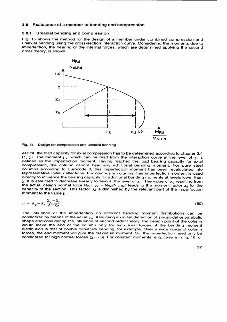
lateral loads within the column length or for sway frames, the imperfection must always betaken into account (Xn = 0), because the design point of the column will always lie within the
column length (fig. 16). For end moments, Xn may be determined according to:
1-r( )n = x, 4 51
where
r is the ratio of the larger to the smaller end moment (- 1 S r S +1)
a) Ff::::::=~~ ~ F b ) F-:f':::~:~ :- F
I + I MF ~ :~ MFI + I I + +,
I~---: I Mf ~~~;J: Mf
I ...T u- -I MF+ Mf MF+ Mf"""'---=_!~~.-/ Mmax
Fig. 16 -Influence of moments from eccentric loads MF combined with moments from imperfections Mf
By means of IJ, the capacity for combined compression and bending of the member is
checked:
MSd S 0.9 J.LMpl.Rd (52)
where
MSd is the design bending moment of the column according to chapter 3.9.
MSd 1 rMSdFig. 17 -Relation of the end moments (- 1 S r S + 1)
The additional reduction by the factor 0.9 covers the following assumptions of this simplified
design method:
-The interaction curve of the section is determined assuming full plastic behaviour of the
materials. No strain limitation needs to be observed.
-The calculation of the design bending moment MSd according to chapter 3.9 is carried out
with the effective stiffness according to chapter 3.4. The influence of the cracking of theconcrete on the stiffness is not covered for higher bending moments by the effective
stiffness alone.
Interaction curves of the composite sections always show an increase in the bending capacity
higher than Mpl.Rd. The bending resistance increases with an increasing normal force,
because former regions in tension are overpressed by the normal force (see chapter 3.6).
This positive effect may only be taken into account if it is ensured that the bending moment
and the axial force always act together. If this is not ensured and the bending moment and
the axial force result from different loading situations, the related moment capacity IJ has to
be limited to 1.0.

8/2/2019 Design Guide for Condrete Filled Hollow Section Columns Under Static Ans Sesmic Loading 5
http://slidepdf.com/reader/full/design-guide-for-condrete-filled-hollow-section-columns-under-static-ans-sesmic 40/70.°OaduAd°o>qaa
u°Ws°MeweO

8/2/2019 Design Guide for Condrete Filled Hollow Section Columns Under Static Ans Sesmic Loading 5
http://slidepdf.com/reader/full/design-guide-for-condrete-filled-hollow-section-columns-under-static-ans-sesmic 41/70
3.8.2 Biaxial bending and compression
The design of a member under biaxial bending and compression is based on its design under
uniaxial bending and compression. In addition to the chapter 3.8.1, the interaction curve of
the section and the moment factor ~ have to be determined also for the second main axis.
The influence of the imperfection needs only be taken into account for the axis, which is more
endangered to fail.
NRclfNpl.Rd NRclfNpl.Rd
1. 0 1.0 @X
X Xd
Xn
0 00 Ilk ILd' Mz.RdlMpl.z.Rd 0 1.0 My.R<t'Mpl.y.Rd
My.sdiMpl.y.Rd 0.90 Y
Mz.sdiMpl.z.Rd
0.9IL
z
Fig. 18 -Design of a member under combined compression and biaxial bending
Often the two main axes of a section have different effective lengths, so that the
determination of the axis, which is more endangered to fail, is evident. On the other hand, the
weak axis of the steel section may not be the same of the total section due to reinforcement.
Also different acting moments may influence the failure on the single axes.
The moment factor ~ should be determined for both main axes, so that the influence of
imperfection on the axes can be checked quickly and the relevant axis for the imperfection
can be determined clearly.
With the related capacities ~y and ~z a new interaction curve is drawn (fig. 18c). The linear
connection of ~y and ~z is cut at 0.9 ~y and 0.9 ~z' respectively, in order to cover small
bending moments (mainly uniaxial bending).
The design is successful if the vector from the bending moments of the two axes lies within
the new interaction curve. This can also be expressed by means of the following equations:
M My.Sd + z.Sd ~ 1.0 (53)
Ily Mpl.y.Rd Ilz Mpl.z.Rd
My.Sd ~ 0.9 (54)
Ily Mpl.y.Rd
Mz.Sd ~ 0.9 (55)
Ilz Mpl.Z.Rd

8/2/2019 Design Guide for Condrete Filled Hollow Section Columns Under Static Ans Sesmic Loading 5
http://slidepdf.com/reader/full/design-guide-for-condrete-filled-hollow-section-columns-under-static-ans-sesmic 42/70"°
Pw
~ (
P
'OOeS
'°8S
3S(SSH
V
Sp
P~=~N""nO
seOo
eMOwen
sOW&
""°
!OSOWOu
epdU
'u5
sAOW
'5POs
U8GO=sW4°M
5PJ1Oe8
.GOe5uOW
.(0
N
(GO
"
'gA°OA
JMOeO
"°UM
eS15PX
sMw°O
Wed
8eO°Oe
8O°ev
le"
spOw&

8/2/2019 Design Guide for Condrete Filled Hollow Section Columns Under Static Ans Sesmic Loading 5
http://slidepdf.com/reader/full/design-guide-for-condrete-filled-hollow-section-columns-under-static-ans-sesmic 43/70
For this case of loading, eqn. 60 may be used in order to check whether the end moment
MR.Sd is the maximum bending moment or if the effect of the application of the second order
theory leads to a greater moment within the column length.
NSd( arccos r
)2
N ~ 7t ;::} Mmax.Sd = MR.Sd (60)cr
otherwise:
MMmax.Sd = ~ Jr2 -2r cos E + 1 (61)
qt! !!!!!!~~!~~
-E~=~~~]Fig. 20 -Uniform lateral loading
For uniform lateral loading (fig. 20), the moments may be determined according to eqn. 62.
~ [COS(~-EE,)
}Sd (E,) = 2'" 1 (62)
E cos§2
with E according to eqn. 59.
The position of the maximum moment within the column length due to uniform lateral loadingis E,= 0.5.
t F
t ;.~ -1- te:!1 I
Fig. 21 -Single lateral load
For a single lateral load (fig. 21), eqns. 63 and 64 lead to the moment distribution over the
column length following the second order theory.
.sin (E-aE) sin EE,region 1: M Sd (E,) = FI . (63 )sin E
. 2 . M (") - FI sin Ea sin EE,(64)egion. Sd " -.
E sin E
where a is the position of the single lateral load according to fig. 21.
For the combination of loadings (end moments and lateral loads), these formulae can be
superposed, if the axial load is the same in all cases. So the moment distribution and the
maximum moment due to practically any loading may be determined. On the other hand,
these formulae seem to be complicated because of the trigonometrical functions in them, so
that they might only be used using a computer.

8/2/2019 Design Guide for Condrete Filled Hollow Section Columns Under Static Ans Sesmic Loading 5
http://slidepdf.com/reader/full/design-guide-for-condrete-filled-hollow-section-columns-under-static-ans-sesmic 44/70
"nS1eXeeeJeS
leS4e
IOeeUeDPpoM0ne
8/2/2019 Design Guide for Condrete Filled Hollow Section Columns Under Static Ans Sesmic Loading 5
http://slidepdf.com/reader/full/design-guide-for-condrete-filled-hollow-section-columns-under-static-ans-sesmic 45/70
3.9.3 Simplified method for the determination of bending moments
For a quick and simple hand calculation, the maximum design bending moment for a
composite column may be determined by multiplying the maximum first order bending
moment by a correction factor k according to eqn. 65.
~k =~ 1.0
1-~ (65)
Ncr
where NSd is the design normal force,
Ncr is the buckling load according to eqn. 21
andB is a factor considering the first order moment distribution according to the
eqn. 66.
~ = 0.66 + 0.44 r but ~ ~ 0.44 (66)
The formula for ~ (eqn. 66) has been derived by comparing the results of the calculation with
the linear formula of eqn. 66 with the results from the exact formula (eqn. 61). For the
relationship of the end moments r = 1, the value of ~ becomes 1.1. This is exactly the factor ~
for NSd/Ncr = 0.4, which may be taken as the upper value for the common applications. The
comparison led to higher discrepancies for the values of ~ less than 0.44. Therefore ~ = 0.44
has been taken as the lower limit value. For columns with lateral loads, the value of ~ hasalways to be taken as ~ = 1.0.

8/2/2019 Design Guide for Condrete Filled Hollow Section Columns Under Static Ans Sesmic Loading 5
http://slidepdf.com/reader/full/design-guide-for-condrete-filled-hollow-section-columns-under-static-ans-sesmic 46/70
S~~O~Ou
e~Mw
(e
'e~M
p(e
!
"u~
e8u~Ow~O
eO~O
s~~OeW
SU
'L£~O
'pUO~W
u~~u~
!O~uU~S
'u~
o~uO
:~OW~e
'p
sgO
UM
S~°
6Up
!OWS
e~~M
'S
dUU
AS~eW~
'SW~
U~Ue~O
'~U
'p
(NO
!O
w~
'e~U
pOO
'U~O~
P°
eO~~O
sW
UU

8/2/2019 Design Guide for Condrete Filled Hollow Section Columns Under Static Ans Sesmic Loading 5
http://slidepdf.com/reader/full/design-guide-for-condrete-filled-hollow-section-columns-under-static-ans-sesmic 47/70
distribution for Mpl.Rd. The sum of the components is again equal to the total bending moment
(eqn. 71).
~ NSd.o/~ MSd.o
fcd r---=-l
fydL=~==~~t~~~
!1~rl~~f! ' !i.MSd
.:::::::::,':::::~;:::.: ~) lvSdi~;llf~ll !
fcd I -I
[~~~~~~===~~=f
~~ MSd.u=MSd.o+!i.MSd
i NSd.u=NSd.o+SdFig. 22 -Difference of forces in a load introduction region -plastic stress distribution
M M M M +M~ = ~ and c+s.Sd = c.Rd s.Rd (70)
MSd Mpl.Rd MSd Mpl.Rd
Mpl.Rd = Ma.Rd + Mc.Rd + Ms.Rd (71)
Generally, the combinations of the internal forces and moments NSd and MSd act on the
column, so that the interaction between Npl.Rd and Mpl.Rd has to be observed. The
components of the cross-sections may be determined for any combination of NRd and MRd'
In the case of introducing the forces from the steel to the concrete part (the most common
way of a connection) the maximum differences of forces may be taken for the design of the
bond area, which lies on the safe side. The maximum difference of normal forces results at
the interaction point -Npl.Rd -(eqn. 68, 69), while the maximum difference of bending
moments occurs at the point of the maximum bending moment resistance -Mmax.Rd -(eqn.
72). These values may be determined easily as shown in the chapters 3.5 and 3.6.

8/2/2019 Design Guide for Condrete Filled Hollow Section Columns Under Static Ans Sesmic Loading 5
http://slidepdf.com/reader/full/design-guide-for-condrete-filled-hollow-section-columns-under-static-ans-sesmic 48/70
apaU~PS~O
ee
~:
'A
5OOueUSdM1e
"edOOeeSee
4Meedee0v
"O1eO~
AeSnOsd
peee4°M°
UeOSeOee
(
.4
eeo°O1
-eenu°u~eu
uO
"AnenA
eoeUed
eOe~POw
sOeaaOdaOdO
P
,
~+
-~ -
;
P
(
p(Gd
p~~

8/2/2019 Design Guide for Condrete Filled Hollow Section Columns Under Static Ans Sesmic Loading 5
http://slidepdf.com/reader/full/design-guide-for-condrete-filled-hollow-section-columns-under-static-ans-sesmic 49/70
Example for the behaviour of buildings with reinforced concrete columns under the South Hyogo Earth.quake of January 17, 1995 in Japan. The building collapsed up to the third storey.
Typical collapse of a building with reinforced concrete columns in the South Hyogo Earthquake in Japan.One mid-story is totally destroyed.

8/2/2019 Design Guide for Condrete Filled Hollow Section Columns Under Static Ans Sesmic Loading 5
http://slidepdf.com/reader/full/design-guide-for-condrete-filled-hollow-section-columns-under-static-ans-sesmic 50/70
-(d
¥
'eAe
'wN'edMe
'uo
(:
SedMOOUUUp
q
.q
"e
9e5ee
~Ue
'sedMe
eUed5
udsse
AUUMooe
euuOeUp
'eMsoOMd
e4O
'~ue5eUP
puoed

8/2/2019 Design Guide for Condrete Filled Hollow Section Columns Under Static Ans Sesmic Loading 5
http://slidepdf.com/reader/full/design-guide-for-condrete-filled-hollow-section-columns-under-static-ans-sesmic 51/70
/~ MSd
.NSd
,
!
f f f f f f f f f fc,Sd u1.Rd
.--=J ts
Fig. 26 -Design proposal for connections with inserted plates

8/2/2019 Design Guide for Condrete Filled Hollow Section Columns Under Static Ans Sesmic Loading 5
http://slidepdf.com/reader/full/design-guide-for-condrete-filled-hollow-section-columns-under-static-ans-sesmic 52/70
1O4M~s0OOD
eDeOd4oeO%
~eOpUqDDoOA
De4o
eMMPeWnS
D~eSSedUDe
eo4e
eMSoUe
s°e
'uoeOneuen
uoeOUoSn
SeUoeO
"oOAUAoeODeUuoeO%
!OeMosoM
seUoe
ueo
eePeW
s°ea
SSe
(
"DeoedS
e0eSS
ewdvOD
'sMeOde
MMoSdo
eMJeO
se
sqe

8/2/2019 Design Guide for Condrete Filled Hollow Section Columns Under Static Ans Sesmic Loading 5
http://slidepdf.com/reader/full/design-guide-for-condrete-filled-hollow-section-columns-under-static-ans-sesmic 53/70
View of the buildings after carthquake on the road with the bank office building shown in page 53.
5.4 Special concrete
Only a few investigations are known with columns filled with special concrete. Steel fibre
reinforced concrete has been used in some of them. This is of small advantage, because the
compression strength is comparable to that of normal weight concrete. The higher tension
capacity of the concrete is not necessary for the concrete filled sections in normal design
situations. The tests under fire situations demonstrated higher resistances when steel fibre
reinforced concrete was used.
The use of high strength concrete in the steel hollow sections is now under investigation. The
general investigation with high strength concrete has shown that the tension capacity of the
concrete is not enlarged in the same way as the compression capacity. For the concrete filled
hollow sections, the tension problem is not so important, as the concrete cannot split away.
So the full advantage of the high compression strength can be obtained from these concrete
filled sections. Design proposals are not yet available. In [10] the results of 23 stub-column
tests and also of 23 tests on slender columns are given. All specimens in this case are
concrete filled rectangular hollow sections. The evaluation of these tests with the method of
Eurocode 4 confirms that the EC4-method is on the safe side for hollow sections filled with
high strength concrete. Similar results have been found in a CIDECT research program [11],
where the confinement effects in concrete filled circular hollow sections could be verified also
for high strength concrete. Additionally it could be shown that the design method for the load
introduction according to eqn. 75 does also work for high strength concrete.

8/2/2019 Design Guide for Condrete Filled Hollow Section Columns Under Static Ans Sesmic Loading 5
http://slidepdf.com/reader/full/design-guide-for-condrete-filled-hollow-section-columns-under-static-ans-sesmic 54/70"e
0oMaSSeSoM
sPpSOgaeaP
4vOepoM0a9
.~ae~eeUa6P>u

8/2/2019 Design Guide for Condrete Filled Hollow Section Columns Under Static Ans Sesmic Loading 5
http://slidepdf.com/reader/full/design-guide-for-condrete-filled-hollow-section-columns-under-static-ans-sesmic 55/70
6 Design for seismic conditions
Strong earthquakes are rare events. When they occur, the yield strength of a typical frame
structure is often exceeded and plastic mechanisms form (e.g.: rotating plastic hinges). In asophisticated earthquake resistant design, two questions are taken into consideration and
need to be checked.
1. Is the structure able to resist the earthquake loading or does it collapse, because the
ductility capacity (or supply) is smaller than the ductility demand?
2. Is the maximum deformation during the earthquake response sufficiently small, so that an
adequate degree of reliability against unacceptable damage can be ensured?
The consideration of these two aspects, which are denoted as strength and ductility and
limitation of deformation in the following, are of basic importance in the course of each
earthquake resistant design.
Most structural damages are due to the use of an unsuitable structural type or to the use of
non-ductile materials, probably of a poor quality. Furthermore, a proper detailing plays an
important role. As for the aspect of strength and ductility, the structural layout should strictly
follow the principles of the "capacity design method", a method which is also mentioned in
Eurocode 8 [16]. Thus, a basic requirement for an optimum overall energy dissipation, mainly
by means of hysteretic energy due to plastic reversal stressing, is guaranteed. The "capacity
design method" can be characterized as follows ([17], [18]): "In a structure, the plastified
regions are deliberately chosen, and correspondingly designed and detailed, so that they are
sufficiently ductile. The other regions are given a higher structural strength (capacity) than the
plastified ones, in order that they always remain elastic. In this way it is guaranteed that the
chosen mechanisms, even in the case of large structural deformations, always remain
functional for energy dissipation."
In order to meet the requirements of a reasonable limitation of deformation, a sufficient load
carrying capacity, but above all a high structural stiffness needs to be provided.
For each type of frame structure, the formation of plastic hinges in the columns should be
avoided as far as possible and other mechanisms, such as plastic hinges in the beams or
plastic shear mechanisms in eccentric braced frames, should mainly contribute to the overall
energy dissipation. The importance of complying with the "weak beam-strong column-
concept" is demonstrated by the example of the multi-storey moment resisting frame shown
in fig. 28. On the one hand, it can be seen that many plastic hinges in the ("weak") beams
lead to a good-natured behaviour combined with an excellent energy dissipation (fig. 28a).
On the other hand, it can be observed that the dangerous "soft-storey-mechanism" with only
four plastic hinges in the ("weak") columns leads to a poor energy dissipation and a much
higher ductility demand (62» 61) with the same maximum displacement vmax (fig. 28b).
@ @Vmax
IIII 82»61
I6
Fig. 28 -Comparison of a favourable with an unfavourable hinge-mechanism [17]

8/2/2019 Design Guide for Condrete Filled Hollow Section Columns Under Static Ans Sesmic Loading 5
http://slidepdf.com/reader/full/design-guide-for-condrete-filled-hollow-section-columns-under-static-ans-sesmic 56/70
£a
[le
gOOaOo
O~:C
eg
O
30
0C
3
O~~
o
D
"eeqfeoMop
leWeUJe
uMd5eene
'8nee
54Mdnd
-oU
eMoMo
"OdeJee
seeOeee
e5eUo
eMoOs"4M
JdO
SSsPPnOe
uodJO
fodo
5MdeUJ

8/2/2019 Design Guide for Condrete Filled Hollow Section Columns Under Static Ans Sesmic Loading 5
http://slidepdf.com/reader/full/design-guide-for-condrete-filled-hollow-section-columns-under-static-ans-sesmic 57/70
7 References
[1] CIDECT Monograph No.1: Concrete filled hollow section steel columns design manual,
British edition, Imperial units, CIDECT, 1970 .
[2] CIDECT Monograph No.5 -Calcul des Poteau x en Profiles Creux remplis de Beton,Fascicule 1 -Methode de Calcul et Technologie de mise en ceuvre, Fascicule 2 -
Abaque de calcul, CIDECT, 1979.
[3] Twilt, L., Hass, R., Klingsch, W., Edwards, M., Dutta, D.: Design guide for structural
hollow section columns exposed to fire, CIDECT series "Construction with hollow steel
sections", ISBN 3-8249-0171-4, Verlag TOV Rheinland, K6In,1994.
[4] Eurocode No.4: Design of Composite Steel and Concrete Structures, Part 1.1: General
Rules and Rules for Buildings, ENV 1994-1-1: 1992.
[5] Rondal, J., WOrker, K.-G., Dutta, D., Wardenier, J., Yeomans, N.: Structural stability
of hollow sectios, CIDECT series "Construction with hollow steel sections", ISBN
3-8249-0075-0, Verlag TOV Rheinland, K6In,1992.
[6] Roik, K. and Bergmann, R.: Composite Columns, Constructional Steel Design: An
International Guide, Chapter 4.2, Elsevier Science Publishers Ltd, UK, 1990.
[7] AIJ Standards for Structural calculation of Steel Reinforced Concrete Structures,
Architectural Institute of Japan, 1987.
[8] Canadian Standards Association, CAN/CSA-S16.1-94, Limit States Design of Steel
Structures, Toronto, 1994.
[9] Bridge, R.O., Pham, L., Rotter, J.M.: Composite Steel and Concrete Columns -Design
and Reliability, 10th Australian Conference on the Mechanics of Structures and
Materials, University of Adelaide, 1986.
[10] Grauers, M.: Composite Columns of Hollow Sections Filled with High Strength
Concrete, Chalmers University of Technology, G6teborg, 1993.
[11] Bergmann, R.: Load introduction in composite columns filled with High strength
concrete, Proceedings of the 6th International Symposium on Tubular Structures,Monash University, Melbourne, Australia, 1994.
[12] Australian Standard AS4100-1990, Steel Structures, 1990.
[13] Eurocode No.3: Design of Steel Structures, Part 1.1: General Rules and Rules for
Buildings, ENV 1993-1-1: 1992.
[14] Eurocode No.2: Design of Concrete Structures, Part 1: General Rules and Rules for
Buildings, Final Draft 1990.
[15] Packer, J.A.: Concrete-Filled HSS Connections, Journal of Structural Egineering, Vol.121, No.3, March 1995.
[16] Eurocode No.8: Structures in Seismic Regions, Design, Part 1 -General and Building,
1988.
[17] Bachmann, H.: Earthquake Actions on Structures, Bericht Nr.195, Institut fOr Baustatik
und Konstruktion, ETH ZOrich, 1993.
[18] Paulay, T., Bachmann, H., Moser, K.: Erdbebenbemessung von Stahlbetonhoch-
bauten, Birkhauser Verlag, Basel/Boston/Berlin, 1992.

8/2/2019 Design Guide for Condrete Filled Hollow Section Columns Under Static Ans Sesmic Loading 5
http://slidepdf.com/reader/full/design-guide-for-condrete-filled-hollow-section-columns-under-static-ans-sesmic 58/70(Ou0OGOgOO
(uGG6Od
%%OOO
cw6Ocw6
:~
-OS6MO~uS~
'%~~o~Oq~MU
WWp vOOO
un~~~Ow
:~eUn%pwSOOe
%%gOOOS
:
cwSOOOU
cwS
cwO
:
cwNGWOOOOcwN£WSOO
cWNOWO0~
:
wx
NO
ga
:SSd
z
Og
I~"
D
S
v
JMOn
Sd
8/2/2019 Design Guide for Condrete Filled Hollow Section Columns Under Static Ans Sesmic Loading 5
http://slidepdf.com/reader/full/design-guide-for-condrete-filled-hollow-section-columns-under-static-ans-sesmic 59/70
0 check of local buckling:
~ = ~ = 46.2<60 (table 4)
0 confinement effects:
1110=4.9-18.5.0.15+17.0.152=2.508 (eqn.14)1120= 0.25. (3 + 2.0.15) = 0.825 (eqn.15)
e Mmax.Sd 60. 100a = -N";;;-d = 6000.40.64 = 0.025 (eqn.16)
111 = 2.508. (1 -10.0.025) = 1.881 (eqn.12)
112 = 0.825 + (1 -0.825) .10.0.025 = 0.869 (eqn.13)
Npl.Rd = 110.0. 25.0 .0.869 + 1138.1 .2.0 (1 + 1.881 ~ ~)
+49.1.43.5 = 7651.6kN (eqn.11)
increase in the bearing capacity caused by confinement: 7651.6/716.1 = 1.07 = 7%
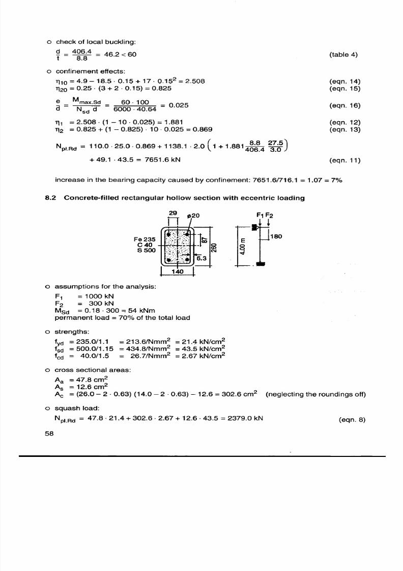
8.2 Concrete-filled rectangular hollow section with eccentric loading
29 20 F1 F2
Fe 235 180
C408500
140
0 assumptions for the analysis:
F1 =1000kNF2 = 300 kN
MSd = 0.18 .300 = 54 kNm
permanent load = 70% of the total load
0 strengths:
fYd = 235.0/1.1 = 213.6/Nmm2 = 21.4 kN/cm2
fsd = 500.0/1.15 = 434.8/Nmm2 = 43.5 kN/cm2
fcd = 40.0/1.5 = 26.7/Nmm2 = 2.67 kN/cm2
0 cross sectional areas:
Aa = 47.8 cm2
As = 12.6 cm2
Ac = (26.0 -2 .0.63) (14.0 -2 .0.63) -12.6 = 302.6 cm2 (neglecting the roundings off)
0 squash load:
Npl.Rd = 47.8.21.4 + 302.6.2.67 + 12.6 .43.5 = 2379.0 kN (eqn.8)

8/2/2019 Design Guide for Condrete Filled Hollow Section Columns Under Static Ans Sesmic Loading 5
http://slidepdf.com/reader/full/design-guide-for-condrete-filled-hollow-section-columns-under-static-ans-sesmic 60/70N"G
I~
£O (u<
:U~
(qO
:En~
(0G1OUv
:Ee
G(G
:P~
(GN90
:S~
:EXXE~
£(q~
:~EO~
G (5~
v
ev
:SXneOu
G (5~VV
sv
ev
:SXneOu
0G9 %vG
:uOOE
(OO6LO

8/2/2019 Design Guide for Condrete Filled Hollow Section Columns Under Static Ans Sesmic Loading 5
http://slidepdf.com/reader/full/design-guide-for-condrete-filled-hollow-section-columns-under-static-ans-sesmic 61/70
.check for the strong axis (compression and bending):
0 determination of X
0 effective stiffness:
(EI) e = 21000 (4260 + 954) + 0.8 ~15122 = 140.9.106 kN cm2 (eqn.22)
0 buckling load:
N =140.9.106.7t6=8691.4kN ( 21)r 4002 eqn.
0 relative slenderness:
j;, = 47.8.23.5 + 3~~~1..~.0:t 19.6. 50.0 = 0.584 < j;,lim (eqn.20)
0 buckling curve a:
X = 0.896 (table 7)
0 cross-section interaction curve:
0 plastic section moduli (neglecting the roundings off)
Wps = 12.6.8.7 = 109.6 cm3 (eqn.36)
Wpc = 12.74 ~ 24.742 -109.6 = 1839.8 cm3 (eqn.32)
Wpa = 1.1~~~-1839.8-109.6=416.6cm3 (eqn.33)
0 interaction point D:
1MO.Ad = 416.6.21.4+2 1839.8.2.67+109.6.43.5= 16138.9kNcm (eqn.30)
1NO.Ad = 2302.6.2.67 = 404.0 kN (eqn.31)
0 interaction point C and B:
NC.Ad = 2 NO,Ad = Npl.c.Ad = 808.0 kN
it is assumed that no reinforcement lies within the region of 2 hn (Asn = 0.0)
808.0hn = 2.14.0.2.67+4.0.63 (2.21.4-2.67) = 4.59cm (eqn.37)
the assumption for Asn is verified
0 plastic section moduli of the cross sectional areas in the region of 2 hn = 9.18 cm:
Wpsn = 0.0
Wpcn = (14.0 -2.0.63) .4.592 = 268.4 cm3 (eqn.40)
Wpan = 2.0.63.4.592 = 26.5 cm3 (eqn.41)
1Mn.Ad = 26.5.21.4 + 2 268.4.2.67 = 925.4 kNcm (eqn. 39)

8/2/2019 Design Guide for Condrete Filled Hollow Section Columns Under Static Ans Sesmic Loading 5
http://slidepdf.com/reader/full/design-guide-for-condrete-filled-hollow-section-columns-under-static-ans-sesmic 62/70g£d ~O
l
"d ,"B0
,d"
l
'd "
'6dd "WV0B
N
Pdd '"
NN
eUUeS
(6O
W96£G6~
(u~
(WBGc
(Ow6Gc
eW9
3dMnSd
N6L
N06
(GG9G~GgGOv
(GGG
:Oe
Wgv
W6
:uOnenS
epedneMeUee
ou3OenU
leoOeu0OO£d
:UU
(u9=d

8/2/2019 Design Guide for Condrete Filled Hollow Section Columns Under Static Ans Sesmic Loading 5
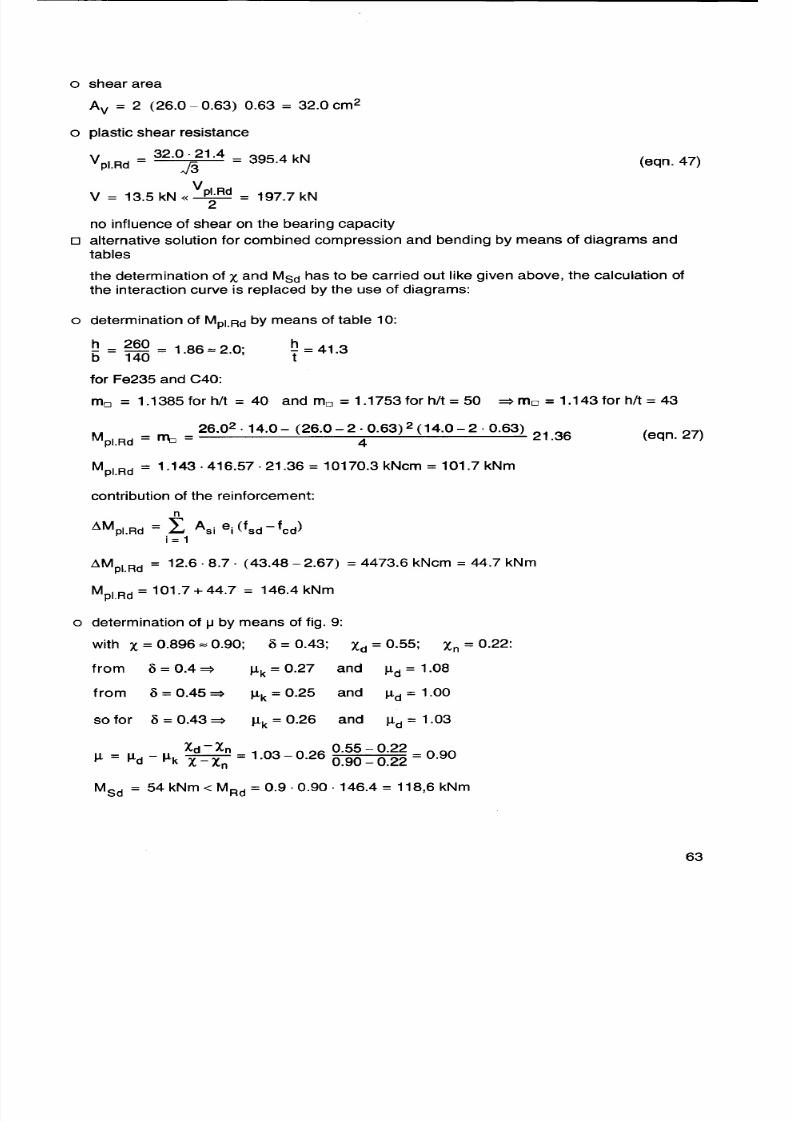
http://slidepdf.com/reader/full/design-guide-for-condrete-filled-hollow-section-columns-under-static-ans-sesmic 63/70
0 internal forces according to first order theory
NSd = 1300 kN; max MSd = 54 kNm
0 check for the second order theory
--Alim = 0.2 (2 -r) = 0.4 < A = 0.584 (eqn. 56; r = 0)
NSd 1300.0~ = 86"91-:4 = 0.15> 0.1 (eqn.57)
0 k-factor for the second order theory:
k = 0.66 = 0.77 < 1.0 with r = 0 => fi = 0.66
1- ~ (eqn.65)8691.2
the end moment is the maximum moment (k = 1.0)
0 check for compression and uniaxial bending
1-r 1-0Xn = X 4 = 0.90 ~ = 0.22 (eqn.51)
1300.0Xd = 237M = 0.55
NRcYNpl.Rd
1.0
X=0.90
0.75
Xd = 0.90
L- ~ = 0.64i ---4,
o. ~ .
Xn=0.22 I I0.17 t t
, B I , MRcY pl.Rd
0.0 0.49 1.0 1.06
from the interaction curve:
~ = 0.64
MSd = 54 kNm < MRd = 0.9.0.64. 152.14 = 87.6 kNm
0 shear (it is assumed that the shear is borne by the steel section alone)
MSd 54.0V Sd = -= -= 13.5 kNI 4.0
8/2/2019 Design Guide for Condrete Filled Hollow Section Columns Under Static Ans Sesmic Loading 5
http://slidepdf.com/reader/full/design-guide-for-condrete-filled-hollow-section-columns-under-static-ans-sesmic 64/70
W9B0
00O-
G
EO
0
B
:G0M
:OEWe
wd
wvdV
~
(eSdV
U
:uOu
Wd
(d L0V9v
E
:OG
E0
L
:qOdOWe
:POdU!OnEenOEWe
sq
PPOnOE
fSOU
N
/
(d
eSSd
cwV
E

8/2/2019 Design Guide for Condrete Filled Hollow Section Columns Under Static Ans Sesmic Loading 5
http://slidepdf.com/reader/full/design-guide-for-condrete-filled-hollow-section-columns-under-static-ans-sesmic 65/70
9 Notations
forces and moments
F force
N internal normal force
M internal bending moment
V internal shear force
indices combined with forces and moments (more than one are separated by a dot):
a concerning the steel hollow section
c concerning the concrete part
cr critical, buckling load of a member
F due to forces
f due to initial deformations (imperfections)pi plastic
p plasticR acting at the top or bottom of the column
Rd design resistance
s concerning the reinforcement
Sd design action
y concerning the y-axis of a section
z concerning the z-axis of a section
cross section properties
A area
b width of a section (dimension in the direction of the bending axis)
h depth of a section (dimension transverse to the direction of the bending axis)
d diameter of a circular hollow section
t wall thickness of the hollow section
r corner radius of rectangular or square hollow sections
I moment of inertia
Wp plastic section modulus
indices combined with cross section properties (more than one are separated by a dot):a concerning the steel hollow section
c concerning the concrete part
s concerning the reinforcement
n concerning a special region of a section
1 concerning the area below an inserted plate
V concerning the area for shear transfer
strengths and stiffnesses
E stiffness modulus (Young's modulus)
(EI)e effective stiffnessf strength
indices combined with strengths and stiffnesses (more than one are separated by a dot):
a concerning the steel hollow section
c concerning the concrete part
cub cube
cyl cylinderd design situation
e effective

8/2/2019 Design Guide for Condrete Filled Hollow Section Columns Under Static Ans Sesmic Loading 5
http://slidepdf.com/reader/full/design-guide-for-condrete-filled-hollow-section-columns-under-static-ans-sesmic 66/70
/on
d
'P&seeN
9vQ
:deS
:udd
e~qeMO~~~
:OMv
se~5eo~1a8
u
e
e
S
u~5
Ue~5
~u~5
~~5
UMOe~5
:ppUaM
u°~5ee
f~~~e
5e~e
SS
S
SSe
~u~e
/~e
OUU
JU
(OUe
J~e
~e
f~~5~e
S
ee
:OpeupM
u°~1
u°~1
/~
s
~u~5
ee

8/2/2019 Design Guide for Condrete Filled Hollow Section Columns Under Static Ans Sesmic Loading 5
http://slidepdf.com/reader/full/design-guide-for-condrete-filled-hollow-section-columns-under-static-ans-sesmic 67/70
~ Comite nternationalour e Developpementt 'Etude8,50nstructionubuliare
International Committee
for the Development and Study
of Tubular Structures
CIDECT, foundet 1962 as an international association, joins together the researchresources of major hollow steel section manufacturers to create a major force in theresearch and application of hollow steel sections worldwide.
The objectives of CIDECT are:
0 to increase knowledge of hollow steel sections and their potential application byinitiating and participating in appropriate researches and studies
0 to establish and maintain contacts and exchanges between the producers of thehollow steel sections and the ever increasing number of architects and
engineers using hollow steel sections throughout the world.
0 to promote hollow steel section usage wherever this makes for good engineering
practice and suitable architecture, in general by disseminating information,
organizing congresses etc.
0 to co-operate with organizations concerned with practical design recommen-
dations, regulations or standards at national and international level.
Technical activities
The technical activities of CIDECT have centred on the following research aspectsof hollow steel design:
0 Buckling behaviour of empty and concrete-filled columns
0 Effective buckling lengths of members in trusses
0 Fire resistance of concrete-filled columns
0 Static strength of welded and bolted joints0 Fatigue resistance of joints
0 Aerodynamic properties
0 Bending strength
0 Corrosion resistance
0 Workshop fabrication
The results of CIDECT research form the basis of many national and international
design requirements for hollow steel sections.

8/2/2019 Design Guide for Condrete Filled Hollow Section Columns Under Static Ans Sesmic Loading 5
http://slidepdf.com/reader/full/design-guide-for-condrete-filled-hollow-section-columns-under-static-ans-sesmic 68/70
.~Oee~Jq
>Uepe~Jq1pSWeU
/O
pSOUWJqWueOqvev
(~~0
(O
:
.nSeO6e~eeWMMe-eA~Wq~OdU
'w~ed~
u~eOOp~M~~D~p
eM~Oe~D~~O-~L~MpSqLLLSD
!O~eo~Mov
(3OOOAeOd
(oeU-eeOAe~e1Od
(ood
(3OS~Od
(ePMOd
'pLSq1eM
-o~MuOdOSq
s1eeWe~~q
LMs~Oe~Wv
"nOw~ud
6~qe1
sq
.A
lewe~Mp1eM~Dd-ds~Sved~O
-d~eOOAeee~DM~U1S~
a

8/2/2019 Design Guide for Condrete Filled Hollow Section Columns Under Static Ans Sesmic Loading 5
http://slidepdf.com/reader/full/design-guide-for-condrete-filled-hollow-section-columns-under-static-ans-sesmic 69/70
Present members of CIDECT are:
(1995)
0 British Steel PLC. United Kingdom
0 EXMA, France
0 ILVAForm, Italy0 IPSCO Inc., Canada
0 Laminaciones de Lesaca S.A., Spain
0 Laminoirs de Longtain, Belgium
0 Mannesmannr6hren-Werke AG, Federal Republic of Germany
0 Mannstadt Werke GmbH, Federal Republic of Germany
0 Nippon Steel Metal Products Co. Ltd., Japan
0 Rautaruukki Oy, Finland
0 Sonnichsen AlS, Norway
0 Tubemakers of Australia, Australia0 Tubeurop, France
0 VOEST Alpine Krems, Austria
Cidect Research Reports can be obtained through:
Mr. E. BollingerOffice of the chairman of the CIDECT Technical Commission
c/o Tubeurop FranceImmeuble PacificTSA 2000292070 La Defense CedexTel.: (33) 1/41258181Fax: (33) 1/41258800
Mr. D. Dutta
MarggrafstraBe 1340878 Ratingen
GermanyTel.: (49) 2102/842578Fax: (49) 2102/842578
'1
Care has been taken to ensure that all data and information herein is factual and that numeri-
cal values are accurate. To the best of our knowledge, all information in this book is accurate
at the time of publication.
CIDECT, its members and the authors assume no responsibility for errors or misinterpreta-
tion of the information contained in this book or in its use.

8/2/2019 Design Guide for Condrete Filled Hollow Section Columns Under Static Ans Sesmic Loading 5
http://slidepdf.com/reader/full/design-guide-for-condrete-filled-hollow-section-columns-under-static-ans-sesmic 70/70