Embed Size (px)
Citation preview
UNIVERSITI TEKNIKAL MALAYSIA MELAKA
Design for Die Casting (Spanner)
Thesis submitted in accordance with the requirements of the National
Universiti Teknikal Malaysia Melaka for the Bachelor Degree of
Manufacturing Engineering in Process
By
Mohd. Rizhuan Bin Othman
Faculty of Manufacturing Engineering
May 2007
DESIGN FOR DIE CASTING (SPANNER)
MOHD. RIZHUAN BIN OTHMAN
UNIVERSITI TEKNIKAL MALAYSIA MELAKA
SULIT
TERHAD
√
TIDAK TERHAD
(Mengandungi maklumat yang berdarjah keselamatan atau kepentingan Malaysia yang termaktub di dalam AKTA RAHSIA RASMI 1972)
(Mengandungi maklumat TERHAD yang telah ditentukan oleh organisasi/badan di mana penyelidikan dijalankan)
(TANDATANGAN PENULIS)
Alamat Tetap: Kampung Hujung bechah, 08200 Sik, Kedah Darulaman Tarikh: 09/05/2007
Disahkan oleh:
(TANDATANGAN PENYELIA)
Cop Rasmi:
Tarikh: _______________________ * Tesis dimaksudkan sebagai tesis bagi Ijazah Doktor Falsafah dan Sarjana secara penyelidikan, atau
disertai bagi pengajian secara kerja kursus dan penyelidikan, atau Laporan Projek Sarjana Muda (PSM). ** Jika tesis ini SULIT atau TERHAD, sila lampirkan surat daripada pihak berkuasa/organisasi berkenaan dengan menyatakan sekali sebab dan tempoh tesis ini perlu dikelaskan sebagai SULIT atau TERHAD.
BORANG PENGESAHAN STATUS TESIS*
UNIVERSITI TEKNIKAL MALAYSIA MELAKA
JUDUL: DESIGN FOR DIE CASTING (SPANNER)
SESI PENGAJIAN: 2006/2007
Saya __________________MOHD RIZHUAN BIN OTHMAN____________________ mengaku membenarkan tesis (PSM/Sarjana/Doktor Falsafah) ini disimpan di Perpustakaan Universiti Teknikal Malaysia Melaka (UTeM) dengan syarat-syarat kegunaan seperti berikut:
1. Tesis adalah hak milik Universiti Teknikal Malaysia Melaka. 2. Perpustakaan Universiti Teknikal Malaysia Melaka dibenarkan membuat salinan
untuk tujuan pengajian sahaja. 3. Perpustakaan dibenarkan membuat salinan tesis ini sebagai bahan pertukaran
antara institusi pengajian tinggi. 4. **Sila tandakan (√)
(HURUF BESAR)
FAKULTI KEJURUTERAAN PEMBUATAN
Rujukan Kami (Our Ref) : 19 May 2006 Rujukan Tuan (Your Ref): Pustakawan Perpustakawan Universiti Teknikal Malaysia Melaka UTeM, Ayer Keroh MELAKA. Saudara, PENGKELASAN TESIS SEBAGAI SULIT/TERHAD - TESIS SARJANA MUDA KEJURUTERAAN PEMBUATAN (PROSES PEMBUATAN): MOHD RIZHUAN BIN OTHMAN TAJUK: DESIGN FOR DIE CASTING (SPANNER) Sukacita dimaklumkan bahawa tesis yang tersebut di atas bertajuk “Design for Die Casting (Spanner) ” mohon dikelaskan sebagai terhad untuk tempoh lima (5) tahun dari tarikh surat ini memandangkan ia mempunyai nilai dan potensi untuk dikomersialkan di masa hadapan. Sekian dimaklumkan. Terima kasih. “BERKHIDMAT UNTUK NEGARA KERANA ALLAH” Yang benar, EN. ABDUL RAHIM BIN SHAMSUDIN, TIMBALAN DEKAN(AKADEMIK), Fakulti Kejuruteraan Pembuatan (Penyelia)
UNIVERSITI TEKNIKAL MALAYSIA MELAKA
2.1. Karung Berkunci 1200, Ayer Keroh, 75450 Melaka Tel : 06-233 2421, Faks : 06 233 2414 Email : [email protected]
MO
HD
RIZ
HU
AN
BIN
OT
HM
AN
B
. EN
G (M
AN
UFA
CT
UR
ING
PRO
CE
SS) 2007 UT
EM
i
APPROVAL
This thesis submitted to the senate of KUTKM and has been accepted as partial
fulfillment of the requirements for the degree of Bachelor of Manufacturing
Engineering
(Manufacturing Process). The members of the supervisory committee are as follow:
………………………………………….
Main Supervisor
(Mr. Taufik )
18th MAY 2007
ii
DECLARATION
I hereby, declared this thesis entitled “Design The Die Casting” is the results of my
own research except as cited in references
Signature : ………………………………………….
Author’s Name : …………………………………………
Date : …………………………………………
iii
DEDICATION
“To my beloved family especially my mother and father, Mrs Salmiah Bt Awang
salimin and Mr Othman Bin Mohamed. I thank my parents for performing this
difficult task, and the journey does not end here.
To my supervisor, Mr Taufik for being receptive and critical, and challenging me to
be a better student. To my friends, for your sacrifices, encouragement, and support
towards project accomplishment”
iv
ACKNOWLEDGEMENTS
Alhamdulillah, thanks to Allah caused finally the PSM report are finish after
struggle for about one semester
Special thanks to all parties involved in materializing the publication of this
report caused express my appreciation and gratitude. For a main supervisor, Mr
Taufik thanks of all idea, helping and guidance for doing this project paper.
For Faculty of Manufacturing EngineeringUniversiti Teknikal Malaysia
Melaka, thanks for an opportunity for this semester project with title, “Design The
Die Casting” especially to all staff and FKP lecturer.
Finally, to my parents and family thanks for special moral support in finishing this
project.
Thank you…
v
ABSTRACT
This report is about the design of the die casting that normally used in the
industrial. Die casting is the one of the process that produces the precise product in
the world. Many of the high precision industrial production used the die casting to
produce the product. That why the die casting is the popular process in production.
With the die casting, the manufacturer can produce the small product until the biggest
one depends to the marketing. Thus for this study the main focus is to evaluate the
suitable design for the metal casting process weather it can improve the several
design in the manufacturing field. As we know, die casting is the one of the important
section that produces the entire products that used in the company, home, school etc.
Some of the product such as sport rims, spanners and others. So, the design process is
important to make sure the product is suitable to use by customer. It is the direct
reason why the die casting design is important in production. Before the design is
approved, all of the concepts about the die casting are included in the introduction
and literature review. Die casting is a process while liquid metal are injected into
steel dies under high pressure and net shape parts are produced after subsequent
metal solidification and cooling. The projects is focused to design the selection
design and produced the design using the selected machine such as milling, lathe,
wire cut and others. To design the selection part, IRONCAD software are use to
produce the design.Through this design, it can produce the high quality design of the
die casting. For the result, the die prototype is successfully produced and all of the
process, design, and NC code are successfully included in this thesis. From that, its
also can help us to know more about the die casting industry.
vi
ABSTRAK
Tesis ini berkaitan dengan reka bentuk tuangan beracuan yang biasanya
digunakan dalam industri. Tuangan beracuan adalah satu proses yang digunakan
untuk mengeluarkan produk yang berketepatan tinggi dan ini merupakan salah satu
faktor mengapa banyak sektor perindustrian mengggunakan proses ini untuk
menghasilkan produk yang jitu. Maka, tidak hairanlah mengapa proses tuangan
beracuan amat populardi dalam proses pengeluaran.Dengan kaedah ini, pengeluar
dapat menghasilkan produk yang kecil atau besar bergantung kepada permintaan
pasaran. Oleh itu, kajian ini berteraskan penilaian kesesuaian rekabentuk untuk
memperoleh satu rekaan yang sesuai untuk dinilai, dihasilkan dan diubahsuai untuk
menjalankan proses tuangan berdai khususnya didalam bidang pembuatan semasa.
Sebagaimana yang diketahui, tuangan beracuan selalu digunakan didalam
menghasilkan produk yang biasa digunakan dalam syarikat, rumah, sekolah dan
sebagainya. contohnya seperti rim sport, spanners dan lain-lain. Maka, proses rekaan
adalah penting untuk memastikan produk adalah sesuai digunakan oleh pelanggan. Ia
mempunyai kaitan langsung mengapa rekaan tuangan beracuan adalah penting di
dalam pengeluaran. Di dalam tesis ini, semua konsep yang berkaitan tuangan
beracuan dapat diperjelaskan lagi didalam pengenalan. dan literasi. Projek ini
berfokuskan untuk merekabentuk salah satu rekabentuk pilihan dan menghasilkannya
dengan menggunakan mesin-mesin pilihan seperti mesin larik,miling, wire cut dan
sebagainya. Untuk merekabentuk setiap bahagian, perisian IRONCAD digunakan
untuk menghasilkan lukisan didalam bentuk ortografik, assembly, exploded dan 3D. menerusi rekabentuk ini, ia dapat menghasilkan reka bentuktuangan beracuan yang
berkualiti tinggi. sebagai keputusannya, prototaip telah berjaya dihasilkan dan semua
proses, reka bentuk, dan kod NC telah dihasilkan.Oleh itu kita dapat mengetahui
dengan lebih jelas perkara yang berkaitan dengan industri tuangan berdai.
vii
LIST OF CONTENTS
APPROVAL ................................................................................................................... i
DEDICATION ............................................................................................................. iii
ACKNOWLEDGEMENTS ......................................................................................... iv
ABSTRACT .................................................................................................................. v
LIST OF CONTENTS ................................................................................................ vii
LIST OF FIGURE ......................................................................................................... x
LIST OF TABLE ......................................................................................................... xi
LIST OF ABBREVIATIONS, SYMBOLS, SPECIALIZED NOMENCLATURE ... xii
INTRODUCTION ......................................................................................................... 1
1.1. Background .................................................................................................. 1
1.2. Scope Of Project .......................................................................................... 3
1.3. Problem Statement ....................................................................................... 3
1.4. Objective ...................................................................................................... 4
To make the project, the objective is important aspect that must be clearly before
make some of the process. The entire objective is shown above; ............................ 4
LITERATURE REVIEW .............................................................................................. 5
2.1. Die Casting Process ...................................................................................... 5
2.2. Die Casting Machine .................................................................................... 9
2.2.1. Cold-Chamber Process ..........................................................................9
2.2.2. Hot-Chamber Process ..........................................................................10
2.2.3. Choosing a casting process .................................................................12
2.3. Furnaces and Metal Handling .................................................................... 13
2.4. Molten Metal Safety ................................................................................... 14
2.5. Casting Cleanup ......................................................................................... 16
2.6. Common Alloys ......................................................................................... 16
2.7. Cost ............................................................................................................. 18
2.8. Effect of Casting Pressure/velocity ............................................................ 19
2.9. Casting Design and Problems .................................................................... 23
viii
METHODOLOGY ...................................................................................................... 25
3.1 Process Flow Chart ..................................................................................... 25
3.2 Gantt Chart ................................................................................................. 28
3.3 Product ....................................................................................................... 30
3.4 Design process ............................................................................................ 30
3.3.1 Several Design (sketch) .......................................................................31
3.3.2 Concept Of Screening Matrix .............................................................35
3.3.3 Concept Of Scoring Matrix .................................................................36
3.3.4 Software selection ...............................................................................37
3.5 Detailed Function ....................................................................................... 38
3.6 Machine selection ....................................................................................... 39
3.7 Material ...................................................................................................... 40
3.6.1 Material for Product ............................................................................41
3.6.2 Material for Die ...................................................................................41
RESULT ...................................................................................................................... 42
4.1 Drawing ...................................................................................................... 42
4.1.1 Auto Cad Drawing ..............................................................................42
4.1.2 Iron Cad Drawing ................................................................................43
4.2 NC Code ( Laser Cutting) .......................................................................... 56
4.3 Prototypes ................................................................................................... 58
DISCUSSION ............................................................................................................. 59
5.1. Material Selection ...................................................................................... 59
5.2. Process to produce prototype ..................................................................... 61
5.3. Casting cycle .............................................................................................. 62
5.4. Metal Injection ........................................................................................... 63
5.5. Time to remove the casting ........................................................................ 64
5.6. Machine dry cycle time .............................................................................. 65
5.7. Cooling time for the die ............................................................................. 67
5.8. Executive summary .................................................................................... 73
CONCLUSION AND SUGGESTION ....................................................................... 74
6.1 Conclusion .................................................................................................. 74
6.2 Suggestion .................................................................................................. 75

ix
REFERENCE ......................................................................................................... 76
APPENDICES ............................................................................................................. 78
x
LIST OF FIGURE
Figure 1.1Flow of the Casting Process (Source from Modenas) ..................................8
Figure 2: The Flow process in Cold Chamber, source from Randall J. Urrbance [10] 9
Figure 3: Illustration of the Cold Chamber Machine[7] .............................................10
Figure 4: Illustration of the Hot Chamber Machine[7] ...............................................11
Figure 5: The Flow process in Hot Chamber, source from Randall J. Urrbance [10] 11
Figure 6: Gantt chart for the process flow ...................................................................27
Figure 7: 3D view of the die casting ...........................................................................37
Figure 8 : die casting part labels ..................................................................................38
Figure 9; Auto Cad Drawing .......................................................................................42
Figure 10; (a)full view, (b)cross sectional view (c)exploded view (d) and (e) die view
.............................................................................................................................43
Figure 11: die prototype for the project; (a) and (b) male side; (c) and (d) female side;
(e) and (f) the die (male side and female side) ....................................................58
xi
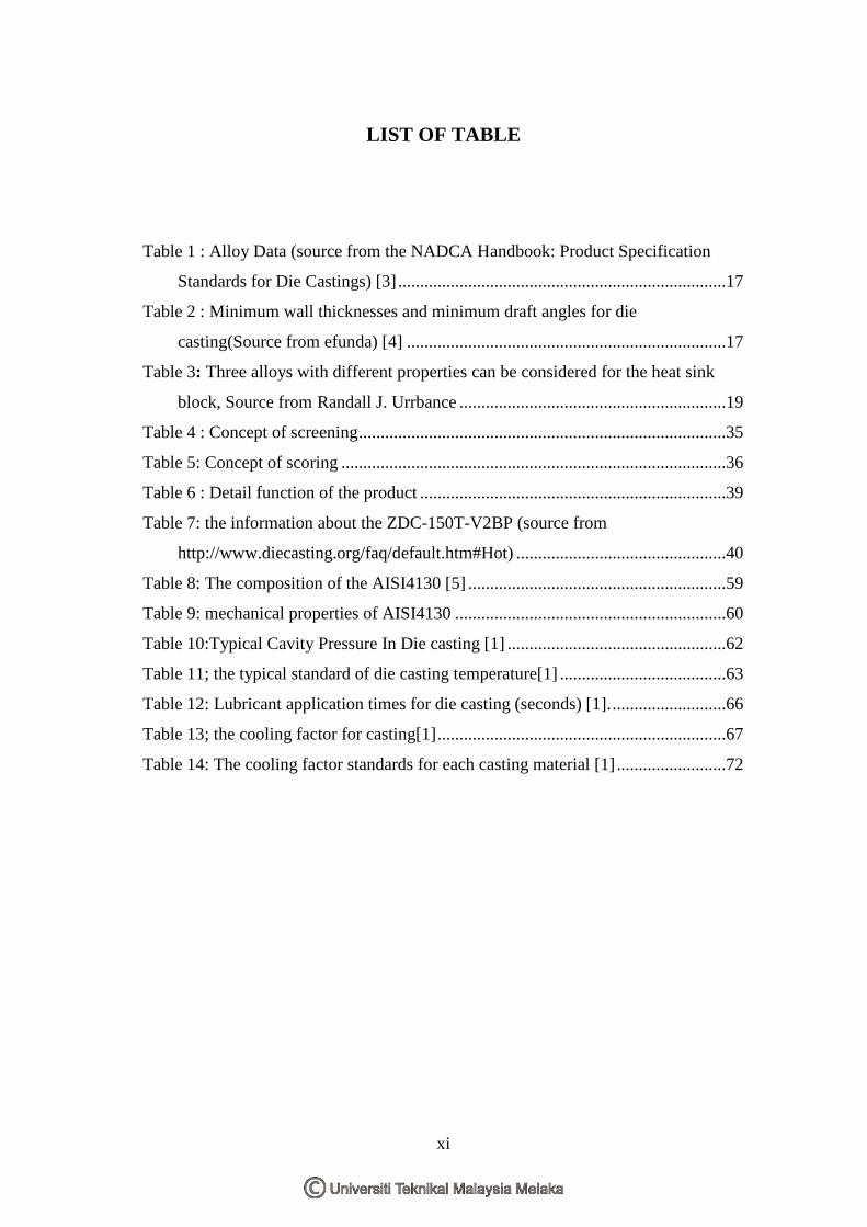
LIST OF TABLE
Table 1 : Alloy Data (source from the NADCA Handbook: Product Specification
Standards for Die Castings) [3] ...........................................................................17
Table 2 : Minimum wall thicknesses and minimum draft angles for die
casting(Source from efunda) [4] .........................................................................17
Table 3: Three alloys with different properties can be considered for the heat sink
block, Source from Randall J. Urrbance .............................................................19
Table 4 : Concept of screening ....................................................................................35
Table 5: Concept of scoring ........................................................................................36
Table 6 : Detail function of the product ......................................................................39
Table 7: the information about the ZDC-150T-V2BP (source from
http://www.diecasting.org/faq/default.htm#Hot) ................................................40
Table 8: The composition of the AISI4130 [5] ...........................................................59
Table 9: mechanical properties of AISI4130 ..............................................................60
Table 10:Typical Cavity Pressure In Die casting [1] ..................................................62
Table 11; the typical standard of die casting temperature[1] ......................................63
Table 12: Lubricant application times for die casting (seconds) [1]. ..........................66
Table 13; the cooling factor for casting[1] ..................................................................67
Table 14: The cooling factor standards for each casting material [1] .........................72
xii
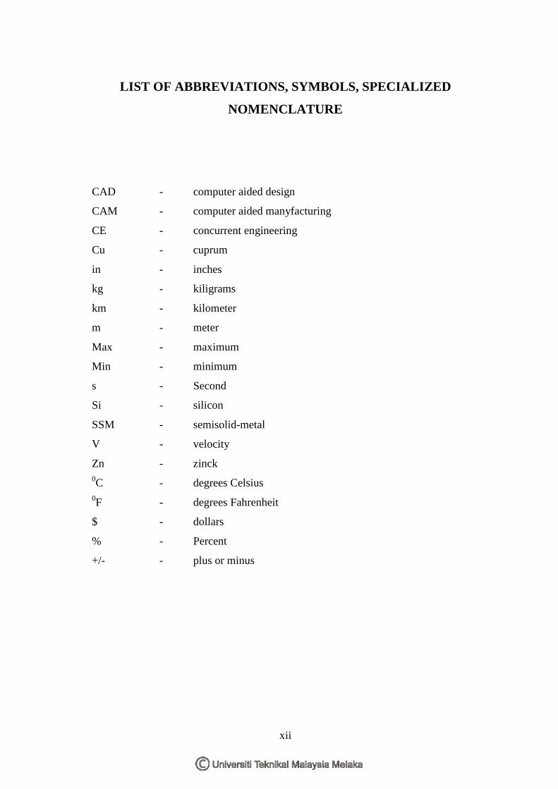
LIST OF ABBREVIATIONS, SYMBOLS, SPECIALIZED
NOMENCLATURE
CAD - computer aided design
CAM - computer aided manyfacturing
CE - concurrent engineering
Cu - cuprum
in - inches
kg - kiligrams
km - kilometer
m - meter
Max - maximum
Min - minimum
s - Second
Si - silicon
SSM - semisolid-metal
V - velocity
Zn - zinck 0C - degrees Celsius 0F - degrees Fahrenheit
$ - dollars
% - Percent
+/- - plus or minus
1
CHAPTER 1
INTRODUCTION
1.1. Background
Metal casting has always been one of the most important and widely used
manufacturing processes. Egyptians used solidification processing to create near net-
shaped components 5100 years ago. As this processing developed, it markedly
expanded with the industrial revolution and advanced technology through the 20th
century. The manufacture of die-casting molds or injection molds is a precise yet clean
production process. Casting is applied widely in the motor, aeroplane, ship,
electronics, and precision machinery industries, etc., because it can produce high-
strength high-quality casting. It has a profound influence on the speed and accuracy
demanded by modern industries. Die casting is a precision casting method of
injecting molten metal into a die cavity applying a high pressure (cold chamber
method: 170–2000 km cm−2, hot chamber method: 90–500 km cm−2) and making use
of high velocity (20–60 m s−1).
Whether the forming of a casting is successful or not is always determined by
the flow system of the casting. In the die-casting process there are many complex
factors that determine the casting quality and the production. In carrying out the die-
casting process, the plane of the casting generally determines the accuracy of the
mold-surface profile; the arrangement and shape of the gate, runner, sprue, pouring
basin, overflow, air vent, etc., being the most important factors in the design of the
die-casting die.
In recent years, modern industries have been demanding esthetically
satisfactory surface curves in product design, and so the mold-surface has become
2
increasingly more complex. During the die casting process, liquid metal is injected
into steel dies under high pressure and net shape parts are produced after subsequent
metal solidification and cooling. After the parts are ejected, the dies are sprayed with
a lubricant, and the process cycle starts again. Lubricants facilitate the ejection of the
finished product and cool the dies.
Further, die design is still dependent on the experience of operators, and due
to the lack of analytical ability in die and melting metal flow and heat transfer, die
design is unable to know and handle the deformation resulting from material and
thermal expansion and shrinkage of the die. Finite elements analysis software is
capable of analyzing the flow condition of the injected metal and the stress, strain and
temperature distribution conditions of the product (the work-piece) under various
injection conditions, but the establishment of an analytical model is very difficult. For
understanding of the die, and the metal flow and solidification process, the user
should be fully acquainted with the basic finite element software.
The application of die castings is expanding continuously. The construction of
die castings is becoming more complex and large-sized, and at the same time a
shorter development cycle of new die casting products is required. How to produce
high quality die castings in a shorter period with a lower cost has become an
important and urgent task of die casting enterprises. Recently concurrent engineering
(CE) has been introduced into die casting production, and the CAD/CAE/CAM
integrated system of die casting dies has been established. In the CE process, the first
step is to create a 3D part database for use in all aspects of the production process.
The next step is to design the die casting process, which includes the design of gating
system, overflows and cooling channels and whole set of die casting dies. So, those
are the same of the process to make the design in this project.
3
1.2. Scope Of Project
This project is about the die casting design aspect in the manufacturing process. The
major scope of this project is specifically to design the suitable system in the die
casting. The project is focused to design the die casting system includes the die. For a
practical, the side of the project is to design the die and produce the die using all of
the machine in the lab. For a design, The IRONCAD software are used to design the
project based to the selection design. The design are selected using the screening and
scoring concepts.Besides that, all of the aspect about the material and the several
designs that we have in the manufacturing process must be know to produce the
quality of the design. In doing this project, it required to design the die casting, which
includes the design of gating system, overflows and cooling channels and whole set
of die casting dies.
1.3. Problem Statement
The manufacture of die-casting molds or injection molds is a precise yet clean
production process. Casting is applied widely in the motor, aeroplane, ship,
electronics, and precision machinery industries. The main problems that are want to
focus in this project paper is about the die casting design that are including the
suitable aspect such as machine, product and the material. This project also was
proposed to design the complete system of the die casting. As we know, the entire
thing we do should have a planning to make sure our job is smooth. So in the
industry, especially in highly risk, to design the die casting it must have the planning
and preparation in anything have done to make sure the die design is smooth to
produce the product. Sometimes, the die casting failure caused the production will
stop automatically because the safety aspect. So, the die casting design must suitable
to the product and the casting machine that used in the production. If the design is
failed, the product at the final has many defects such as crack, unfilled, weld line and
4
others. The design aspect is important to make sure the die casting system can
function quickly and also produces the product in short cycle time.
1.4. Objective
To make the project, the objective is important aspect that must be
clearly before make some of the process. The entire objective is shown above;
1. To make the suitable design based to the product.
2. To understand the system that used in the die casting.
3. To make the decision of the suitable product, material and machine for the
selection product
4. To produce the detailed drawing of the product.
5. To produce the prototype based to the selected design.
5
CHAPTER 2
LITERATURE REVIEW
2.1. Die Casting Process
The Die casting process, developed in early 1900s, is a further similar to
permanent mold casting except that the metal is injected into the mold under high
pressure of 10-210Mpa (1,450-30,500) psi. This results in a more uniform part,
generally good surface finish and good dimensional accuracy, as well as 0.2 % of
casting dimension. [3]
Die casting is similar to permanent molding in that a metal mould made in
two halves is used. The differenced is that the metal is not gravity poured into the
mould (die), but instead the metal is injected under high pressures ranging from 1000
to 100,000 PSI. This requires massive machine that are generally operated
hydraulically to exert the hundred of tons the force necessary to hold the two halves
of the die together when the molten metal is being injected at such high pressures. [4]
Die Casting is the process of forcing molten metal under high pressure into
the cavities of steel molds. The molds are called dies. Dies range in complexity to
produce any non-ferrous metal parts (that need not be as strong, hard or heat-resistant
as steel) from sink faucets to engine blocks (including hardware, component parts of
machinery, toy cars, etc) [3]. In fact, the process lends itself to making any metal part
that:
1. must be precise (dimensions plus or minus as little as .002 inches--over short
distances),
2. must have a very smooth surface that can be bright plated without prior
polishing and buffing,
6
3. have very thin sections (like sheet metal--as little as .050 inches),
4. must be produced much more economically than parts primarily machined
(multicavity die casting molds operating at high speed are much more
productive than machine tools or even stamping presses),
5. must be very flexible in design; a single die casting may have all the features
of a complex assembly. [3]
Typical parts made through die casting are motors, business machine, appliance
component, hand tools and toys. The weight of most castings ranges from less than
90g (3oz) to about 25kg (55lb). For many parts, post-machining can be totally
eliminated, or very light machining may be required to bring dimensions to size. [3]
The Dies are usually made of alloy or tool steel and are quite expensive to
make. Some have one or two identical mould cavities for larger parts, and others may
have several different cavities. Some dies are more complicated and have sections
that move in several directions. Grooves or overflows around the cavity on the
parting face permit gases to escape. [2]The overflows of excess metal must be trims
off by a secondary operation after the casting is removed from the mould. This
trimming is done with trimming dies that also removes the sprues and runners. The
mould must also have provisions for water cooling so that a constant operating
temperature can be maintained. Knock-out pins provides for injection the parts when
the die is opened. When cores are used they are made of metal and are usually drawn
out before the die is opened. Cores are retracted either in a straight line or in circular
motion.
Complex components with intricate features are commonly pressure die cast
using sophisticated tools. Tool tolerance is critical. Flashing at tool faces can defeat
the economics of die casting if it necessitates deburring or secondary finishing. In
conventional die-casting tools, molten alloy is forced into the cavity until it flashes
out between adjoining surfaces. For zinc-alloy die casting of small components, tools
are assembled to tolerances of +/-0.0001 in. -- a tight seal around the cavity which
eliminates flash. [10]
It easy to see that these complex dies are quite expensive. Their costs can
range from a few thousand dollars to $100,000 depending on the size of the die, its
complexity, and the size of the casting machine used. Obviously, this process is not
7
suitable for small-quantity production or for making very large parts. The large
investment for dies and machines will pay off only when very large quantities
(20,000 to millions of parts per year) are required. [7]
Die casting is means of producing castings of lower levels temperature alloys
at a relatively high rate. These casting are usually thin walled, smooth, and highly
accurate. [3] The process is highly adaptable to the manufacture of small parts such
as automobile door handles, wiper motors, Kitchen appliance parts, and thousands of
small items we used every day.
A die-casting tool is basically a six-sided cube that opens and closes like a
clamshell, with a parting line where the two halves meet. The cavity inside is the
shape of the component to be formed. Any component feature parallel to that
open/close motion is easily incorporated into the two halves with the use of cores.
For example, a fixed core pin in the movable half of the tool forms a center hole. For
features offset from the parting line, movable side cores are driven in a sideways
motion to be retracted before the die-cast component is ejected from the tool. These
cores can be at any angle. For a wheel that requires features on the outside diameter
corresponding to each month of the year, 12 cores are used, one every 30*. [10]
The quality of die castings is high because of a rapid cooling rated that
produces fine grains in the metal. The surfaces tend to be harder than the interior as a
result of the chilling actions of the metal die. Porosity is sometimes a problem as a
result of entrapped air, but with the proper venting this can be overcome. [9]
Cylindrical cores form holes with a 0.001 in. tolerance, which can be tapped
to 60 to 75% full thread without drilling. Side cores enable the production of holes
and undercut features that are parallel to the major parting line of the tool. A movable
core can form a hole or slot of virtually any shape to tolerances of 0.002 in. External,
internal, face, helical, spur and worm gears are cast to angles of 20° and can
incorporate shafts, ratchets, and cams. [10]
Zinc-based alloys are the most commonly used in die casting. Other metals
used in die casting are alloys using copper, aluminum, and magnesium. Zinc alloys
have the lowest melting point, about 7000F (3710C), and so have a less destructive
effect on dies. Aluminum and Magnesium alloys melt at about 11000F (5930C), and
copper alloys melt about 17000F (9270C). Therefore, dies using these alloys have a