Embed Size (px)
Citation preview
Design for an 8 m telescope with a 3 degree �eld at f/1.25- the Dark Matter Telescope
Roger Angel, Michael Lesser, & Roland Sarlot
The University of Arizona, Steward Observatory, 933 N. Cherry Ave.,Tucson, AZ 85721
Edward Dunham
Lowell Observatory, 1400 W. Mars Hill Rd., Flagsta�, AZ 86001
Abstract. Deep images recorded over a wide �eld of view are neededfor astronomical projects as diverse as measuring cosmological parametersby weak gravitational lensing and predicting asteroid collisions with theEarth. Here we give the design for a three-mirror, 8.4 m telescope with anetendue of 260 (m:�)2, ten times greater than any other current or plannedtelescope. Its 3� diameter �eld is formed at f/1.25, and would be recordedby 55 cm diameter circular mosaics of CCDs for wavelengths 0:3� 1�mand HgCdTe devices for 1 � 2:4�m. The plate scale of 51�m/arcsecensures that seeing-limited images will be well sampled by the 10 - 15�mpixel sizes of these detectors. When used to integrate single deep imagesover its 7 square degree �eld of view, the limiting magnitude (10 �) fora 1 night exposure will be U=26.7, B=27.8, V=27.9, R=27.6, I=26.8,J=24.8, H=23.5 and Ks=22.8. When used to �nd faint moving or variableobjects by quickly imaging large �elds, the telescope will be repositionedin 5 seconds while the detector mosaic is read out. Such agility is realizedbecause the telescope is centrally balanced and very compact, little longerthan the primary mirror diameter. By repositioning every 30 seconds, 1steradian per night could be imaged to a limiting magnitude (10 �) ofV> 24 or Ks> 19. For spectroscopic follow-up, several hundred integral�eld units could be used to study rare objects identi�ed by imaging buttoo faint and sparsely scattered for e�cient follow-up with any other largetelescope.
1. Rationale and design considerations
Much of today's cutting edge astronomy makes use of just two types of opticaltelescope: ground based instruments having huge light grasp but with imagequality limited by atmospheric blurring, and the Hubble space telescope withsmall aperture but exquisite image quality. In the future, larger cooled telescopeswith unique sensitivity in the infrared are planned for space, while ground basedtelescopes will be much improved through correction of atmospheric blurringwith adaptive optics. Interferometers will give still higher resolution, though atthe price of proportional reduction in both �eld and sensitivity.
1
Here we consider a new type of ground based telescope, one whose strengthlies not in a small, di�raction limited �eld of view but in having the widest pos-sible �eld with the largest aperture. Equipped with a large mosaic of detectorsto reach sensitivity limits set only by sky photon noise and atmospheric seeing,such a telescope has unique scienti�c potential. It would also be used to probe�elds as large as the whole sky to unprecedented depth. By taking advantageof massive computational power only now becoming available, it would be ableto identify very faint moving and variable objects. Many scienti�c projects arealready envisaged for this Dark Matter Telescope, as described by Armandro�et al. (1999). It will also doubtless be used for projects as yet undreamed of,undertaken with the legacy of a truly enormous data base as well as with newobservations.
A general measure of the power of a telescope is the �gure of merit A�=d.Here A is the collecting area, the solid angle of the �eld of view, � the detectorquantum e�ciency and d the solid angle of the seeing limited image. In givenintegration time the size of �eld larger than that can be explored to givendepth is directly proportional to this �gure of merit. While longer integrationtimes can sometimes compensate for a lower �gure of merit due to reducedimage quality or smaller �eld or aperture, for some speci�c projects individualfactors are decisive. For example, good image quality is essential to detectdark matter by slight changes in shape of distant galaxies, while long exposurescannot substitute for large aperture and good image quality in the detection ofvery faint moving asteroids.
To maximize the �gure of merit for an imaging telescope, it should be ina site with excellent seeing and its focal length must be chosen so the detectorpixels will adequately sample seeing-limited images. Experience shows that goodtelescopes at the best sites will deliver images of 0.5 arcsec on occasion, morefrequently in the near infrared. The pixel sampling should be no worse than0.25 arcsec (the Nyquist sampling criterion) to avoid further signi�cant imagedegradation, thus each square degree on the sky must be sampled by about 200million pixels in the detector mosaic. We would like to cover the 0.3 - 2.4 micronspectral range where the atmosphere is largely transparent and has relativelylow emissivity. This will require two detector array types, most likely siliconCCDs below 1 �m wavelength and HgCdTe arrays above. Both types havequantum e�ciencies, �, near unity. Individual 2048 x 2048 arrays of HgCdTewill be practical in the near future with 15 �m pixels, but not much smaller(Vural, 1999). This pixel size is consistent with future CCDs with high full wellcapacity, as we discuss below. Thus the optimum focal length should be around10 - 12 m.
We have investigated optical designs for telescopes to deliver the largestpossible aperture and �eld consistent with this focal length, with minimal degra-dation of 0.5 arcsec images. The largest convenient monolithic primaries are 8m diameter, which would require imaging at f/1.25 to obtain 10 m focal length.Conventional telescope designs, including Schmidt cameras and other correctedsystems based on one or two mirrors are incapable of wide �elds at so fast afocus, but three-mirror optical systems have this capability, as we now show.
2
2. Three mirror telescope design
2.1. Paul optics
Three-mirror telescopes were �rst explored by Paul (1935). He gave a designwith a parabolic primary, convex spherical secondary and a concave sphericaltertiary of equal but opposite curvature. The image is formed midway betweensecondary and tertiary, with good correction over a wide �eld. One can thinkof the design as a re ective Schmidt telescope used as a corrector for a largeafocal Cassegrain telescope. The secondary, located at the center of curvatureof the tertiary, has added correction for spherical aberration in the manner ofa re ecting Schmidt plate. A telescope of this type with a one degree �eld wasbuilt by McGraw et al., (1982), using a 1.8 m parabolic primary at f/2.2. Thecentral obscuration was 22% by area, and the design gave images no more than0.2 arcsec rms diameter at the edge of the �eld.
The Paul geometry is capable of still wider �elds at fast focal ratio, whenvignetting and central obscuration are minimized. We have explored general 3-mirror systems using ZEMAX, allowing all three mirrors to have aspheric �gureoptimized speci�cally for wide �eld. The wide �eld was not constrained to be at, since the dedicated detector mosaics can be con�gured to approximate acurved �eld, with each at device tangent to the focal surface.
Our �rst investigations were very encouraging in that we found that wellcorrected �elds of 3� diameter or more can be formed at f/1 by the three mirrorsalone. As the �eld is increased beyond 3�, so are the losses due to vignetting andcentral obscuration. Obscuration is caused by the large secondary and tertiaryblocking the primary and by the detector obscuring the beam to the tertiary. Skyba�es needed to prevent any non-focused light from getting to the detector alsoincrease obscuration and vignetting. An optimum design balances obscurationand �eld of view to maximize etendue or A product for given primary aperture.
In a preprint circulated at the Austin AAS meeting (Angel, Dunham, Lesserand Millis, January, 1999), we gave a 3-mirror design with 3� diameter �eld and25% central obscuration with little vignetting. While this design achieved thebasic goals, it had signi�cant limitations. The image formed at f/1 by a 6.5 mtelescope had an uncomfortably small plate scale of 31 �m/arcsec. The designalso had poor achromaticity because of the introduction of a dewar window. De-spite making this as thin as we dared (7 mm of sapphire), longitudinal chromaticaberration limited the breadth of �lter passbands. Furthermore, to minimize vi-gnetting there was inadequate room for thermal ba�ing around the detectors,or for �lters to be stored in the dewar.
2.2. Revised design
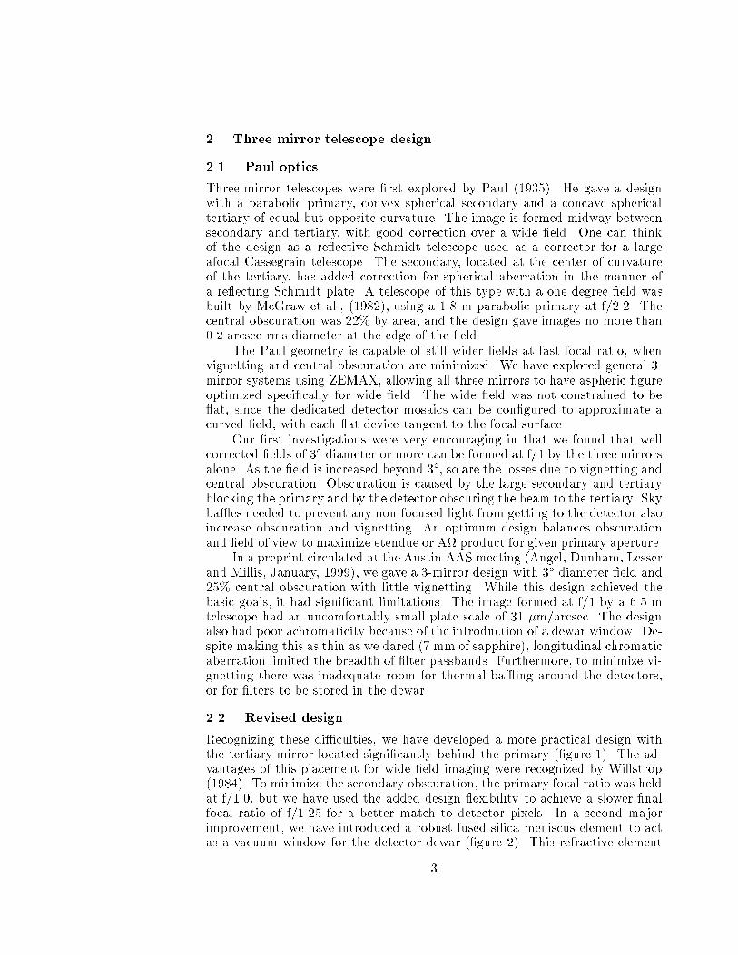
Recognizing these di�culties, we have developed a more practical design withthe tertiary mirror located signi�cantly behind the primary (�gure 1). The ad-vantages of this placement for wide �eld imaging were recognized by Willstrop(1984). To minimize the secondary obscuration, the primary focal ratio was heldat f/1.0, but we have used the added design exibility to achieve a slower �nalfocal ratio of f/1.25 for a better match to detector pixels. In a second majorimprovement, we have introduced a robust fused silica meniscus element to actas a vacuum window for the detector dewar (�gure 2). This refractive element
3
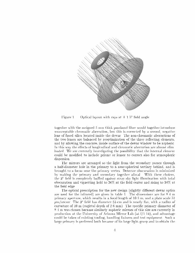
Figure 1. Optical layout with rays at � 1.5� �eld angle.
together with the assigned 5 mm thick passband �lter would together introduceunacceptable chromatic aberration, but this is corrected by a second, negativelens of fused silica located inside the dewar. The non-chromatic aberrations ofthe two lenses are balanced by reoptimization of the three re ecting elements,and by allowing the concave, inside surface of the dewar window to be aspheric.In this way the e�ects of longitudinal and chromatic aberration are almost elim-inated. We are currently investigating the possibility that the internal elementcould be modi�ed to include prisms or lenses to correct also for atmosphericdispersion.
The mirrors are arranged so the light from the secondary passes througha half-diameter hole in the primary to a near-spherical tertiary behind, and isbrought to a focus near the primary vertex. Detector obscuration is minimizedby making the primary and secondary together afocal. With these choices,the 3� �eld is completely ba�ed against stray sky light illumination with totalobscuration and vignetting held to 26% at the �eld center and rising to 38% atthe �eld edge.
The optical prescription for the new design (slightly di�erent dewar opticsare used for the infrared) are given in table 1. The dimensions are for 8.4 mprimary aperture, which results in a focal length of 10.5 m, and a plate scale 51�m/arcsec. The 3� �eld has diameter 55 cm and is nearly at, with a radius ofcurvature of 10 m (sagittal depth of 2.6 mm). The speci�c primary diameter of8.4 m was chosen because similarly aspheric mirrors of this size are currently inproduction at the University of Arizona Mirror Lab (at f/1.14), and advantagecould be taken of existing tooling, handling �xtures and test equipment. Such alarge primary is preferred both because of its large light grasp and to obtain the
4
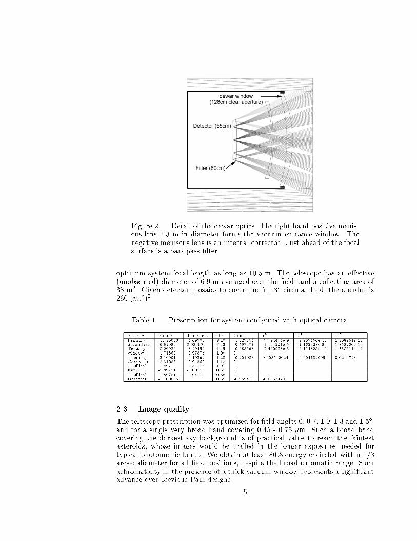
Figure 2. Detail of the dewar optics. The right hand positive menis-cus lens 1.3 m in diameter forms the vacuum entrance window. Thenegative meniscus lens is an internal corrector. Just ahead of the focalsurface is a bandpass �lter.
optimum system focal length as long as 10.5 m. The telescope has an e�ective(unobscured) diameter of 6.9 m averaged over the �eld, and a collecting area of38 m2. Given detector mosaics to cover the full 3� circular �eld, the etendue is260 (m:�)2.
Table 1. Prescription for system con�gured with optical camera
Surface Radius Thickness Dia. Conic r6
r10
r16
Primary -16.80000 -5.09996 8.40 -1.027354 -7.794474e-9 -7.959556e-13 1.808951e-18Secondary -6.59999 3.98969 3.43 -0.597477 -1.104251e-5 -7.162328e-8 1.858206e-10Tertiary -8.26926 -3.29459 4.45 -0.068663 -2.460928e-8 -6.114825e-10 1.788511e-12window -1.71869 -0.07875 1.28 0(silica) -2.16001 -0.19262 1.28 -0.201983 0.003512024 -0.004189095 0.0214793
Corrector -2.31283 -0.01562 1.12 0(silica) -1.49723 -0.51128 1.07 0
Filter -2.89751 -0.00525 0.59 0(silica) -2.89751 -0.04114 0.58 0
Detector -10.00685 0.55 -67.59419 -0.0067470
2.3. Image quality
The telescope prescription was optimized for �eld angles 0, 0.7, 1.0, 1.3 and 1.5�,and for a single very broad band covering 0.45 - 0.75 �m. Such a broad bandcovering the darkest sky background is of practical value to reach the faintestasteroids, whose images would be trailed in the longer exposures needed fortypical photometric bands. We obtain at least 80% energy encircled within 1/3arcsec diameter for all �eld positions, despite the broad chromatic range. Suchachromaticity in the presence of a thick vacuum window represents a signi�cantadvance over previous Paul designs.
5
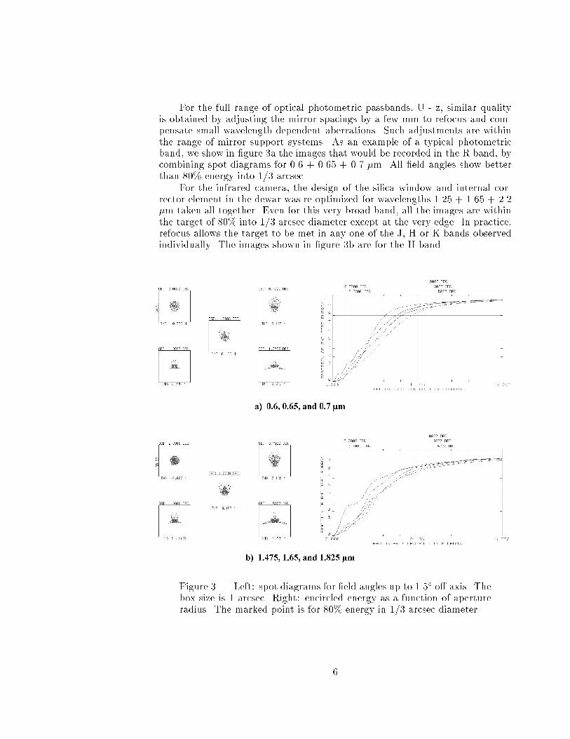
For the full range of optical photometric passbands, U - z, similar qualityis obtained by adjusting the mirror spacings by a few mm to refocus and com-pensate small wavelength-dependent aberrations. Such adjustments are withinthe range of mirror support systems. As an example of a typical photometricband, we show in �gure 3a the images that would be recorded in the R band, bycombining spot diagrams for 0.6 + 0.65 + 0.7 �m. All �eld angles show betterthan 80% energy into 1/3 arcsec.
For the infrared camera, the design of the silica window and internal cor-rector element in the dewar was re-optimized for wavelengths 1.25 + 1.65 + 2.2�m taken all together. Even for this very broad band, all the images are withinthe target of 80% into 1/3 arcsec diameter except at the very edge. In practice,refocus allows the target to be met in any one of the J, H or K bands observedindividually. The images shown in �gure 3b are for the H band.
Figure 3. Left: spot diagrams for �eld angles up to 1.5� o�-axis. Thebox size is 1 arcsec. Right: encircled energy as a function of apertureradius. The marked point is for 80% energy in 1/3 arcsec diameter.
6
2.4. Sky Ba�ing
Through most of the telescope's spectral range, up to 1.8�m, its sensitivity islimited by photon noise from optical emission by the atmosphere. To preventadditional skylight from reaching the focal surface indirectly, two black conicalba�es will be used. The �rst, 4 m in diameter, extends 0.5 m below the sec-ondary mirror (see �gure 4). The second, 3.8 m diameter, rises 1.1 m abovethe primary hole. These two give complete sky ba�ing out to the full 1.5� �eldangle.
Above 2 microns wavelength black body thermal emission from telescopesurfaces rises rapidly and would be the dominant background in the K band. Tominimize such emission it is normal to use re-imaging optics in the dewar, so asto create an entrance pupil image where a cold stop can be located. For this tele-scope with very large �eld and fast focal ratio, pupil reimaging is prohibitivelydi�cult and a new strategy is required. As is conventional, we will remove theupper ba�e, so the secondary is seen against the colder sky background. Inaddition, the infrared mosaic detector is set back in the dewar, 0.8 m behind a1.3 m diameter cold ba�e just inside the entrance aperture. This reduces thesolid angle accepting thermal radiation through the window to 1.4 steradians,still about 3 times the solid angle of the f/1.25 beam (0.45 ster). To furtherreduce this external radiation we take advantage of the fact that the dewarwindow viewed from the outside is a large surface with extremely low emissionin the K band. Thus to block radiation from the lower \tube" supporting thetertiary mirror which is viewed directly by the detector, we propose to line itwith gold-coated retro-re ectors. These would be curved mirror segments withtheir center of curvature on the dewar window. Radiation from other telescopesurfaces seen re ected in the tertiary, such as the back of the primary, will besimilarly blocked by placing in front of them at retro-re ectors. In this way,we expect that the e�ective emissivity over the 1.4 steradians opening couldbe reduced to 0.2. This would cause a thermal background equivalent to thatof 60% emissivity in the f/1.25 beam. From the estimates given by Gillett andMountain (1998), thermal emission at this level would equal the OH backgroundat 2.2�m, would be ten times stronger at 2.4 �m and 4 times weaker at 2.0 �m.Thus the sensitivity should be little compromised in the Ks band, from 2 to 2.2�m.
3. Practical aspects
3.1. Mirrors, windows and �lters
The three large aspheric mirrors needed for the telescope are manufacturable bymethods already proven at the Mirror Lab (Martin et al. 1998). The primary issimilar to the very fast 8.4 m f/1.14 mirrors for the Large Binocular Telescope,now in process. Already the f/1.25, 6.5 m Magellan I mirror has been �nishedto the di�raction limit at 0.5 �m. The 4.5 m concave tertiary is very fast, f/0.8,but is not very aspheric, and should not present any great di�culty. Perhaps themost challenging mirror is the smallest, the convex 3.5 m secondary. A similarlyaspheric 1.6 m Cassegrain secondary for the MMT (Smith et al. 1997) is beingmade at the Mirror Lab, with stressed lap �guring and a computer-generated,
7
full aperture holographic test plate. The same methods would be extended to3.5 m turntables for the �guring and hologram manufacture.
The dewar windows are 1.3 m diameter, and must take vacuum loadingat sea level of about 14 tons. Their convex meniscus shape is favorable, addingshell sti�ness; a preliminary �nite element study kindly made by Warren Davison�nds no stresses larger than 1000 psi for the shape given in the prescription, 79mm thick at the center and 50 mm at the edge. The window would be �guredwith slightly more curvature than needed, to allow for the attening under load.
We envisage intermediate waveband �lters made by multi-layer coatingsdeposited on meniscus glass substrates 60 cm in diameter. In any optical sys-tems with large etendue, the sharpness of interference �lters is limited by theinevitable lack of collimation. Spectral broadening is proportional to the solidangle of rays passing through the �lter. The smallest possible solid angle passingthrough a �lter of area af is A=af . Filters 60 cm in diameter to cover the 3�
�eld at f/1.25 will produce broadening ��=� of about 3%, a practical lower limitfor broadening. George Jacoby has kindly calculated the pro�le of a 24 nm wide�lter at 555 nm (��=� = 4%), and �nds the width is little a�ected comparedto illumination at normal incidence, but the sides become less steep.
3.2. Detectors
CCD detector arrays are now a rather mature technology, and there is littledoubt that a mosaic to cover the full 55 cm circular focal surface can be builtfor acceptable cost. One camera equipped with such a mosaic would alone besu�cient for the key dark matter and asteroid mapping projects. A similarlysized mosaic of infrared detectors represents a greater leap, but is neverthelessfeasible and has enormous potential for study of the universe at high redshiftand as a precursor to NGST. In both cases the individual at detector arrayswill be arranged in the form of a slightly domed mosaic to best �t the focalsurface. There will remain some defocus across each at array, but this can beheld to acceptable level. Thus the 10 m radius of curvature of the focal planeresults in only �8�m of longitudinal defocus for individual square arrays 25 mmon a side.
CCD mosaic A signi�cant issue for CCDs is the control of charge bloomingfrom bright stars. Deep wells, anti-blooming measures and the use of manysmaller devices will all be important control measures. We shall suppose thatdetectors with 13 �m pixels (0.25 arcsec) are used. These should be manu-facturable with deep wells - already full well as high as 150,000 electrons hasbeen demonstrated for 8x8 �m pixels (Tower, 1999). In the future 13 �m pixelscould be optimized for still greater capacity. Anti-blooming capabilities can beincorporated in the detectors, which may reduce the full well capacity. Alter-natively, anti-blooming clocking schemes may be used during integrations. Toavoid uncontrolled blooming from the brightest stars, (a few really bright oneswill be inevitable in a 3� �eld), a large number of smaller format devices maybe preferred. These could be as small as 1024 pixels square, in which case 1300devices would be needed to tile the 55 cm diameter focal plane. We �nd belowthat the read time should be no more than 5 seconds, requiring a realistic 200kHz pixel rate to read each 1024 square device with a single ampli�er.
8
As a way tominimize the gaps between the individual CCDs we are presentlyexploring detector packaging techniques which will allow the use of true, 4-sidebuttable devices using semiconductor industry standard packaging technologies.This development would limit the inter-device gaps to the non-imaging siliconof each detector, which is dominated by clock busses, ampli�ers, and, most sig-ni�cantly, I/O bonding pads. With the continued industry-wide trend towardsmaller I/O structures, it is not unreasonable to expect 50�m bond pads tobe su�cient for future CCDs. If we therefore assume uniform gaps of 100 �maround each CCD, a �ll factor of 96% can be obtained.
Cooling requirements are not severe for the CCD mosaic. The criterion isthat the dark rate be less than the sky photon rate in the darkest �lters. Weestimate that even for the U band or the narrowest 3% �lter that photon rateswill be > 1:5e�/pixel/sec. With an MPP device, dark rates less than this canbe achieved at a device temperature of about -15 C. It follows also that in theworst case of a 20 second exposure in a dark band a read noise of � 4 e� rmswill be acceptable.
While certainly a very large number of devices are required for this project,the CCDs themselves could be manufactured today. The DC shorts yield ofseveral fabrication lines is now over 50%. If 50% of these unshorted thick CCDsare of astronomical quality, a mature lot run will yield about 25% useable devicesfrom 6" silicon wafers at a modern facility. Assuming a 25-50% thinning andpackaging yield, the �nal thinned device yield would be about 5-10% of thestarting lot. This would then require about � 200 wafers to be fabricated with100 devices per wafer, after one or two engineering and test lots. CryogenicDC and AC wafer probing will allow rapid feedback to the fabricator on devicequality and yield.
Infrared arrays The main issues for the infrared concern production time andcost for the large number of devices needed. Supposing that HgCdTe with 2048 x2048 15 �m pixels are used, 250 are needed to fully populate the 3� focal surface.Production of this large a number should be feasible over a period of a few years,but techniques to lower cost need to be developed. For such a large productionrun, the long wave cut-o� could be tailored to suit the application, and would beset at about 2.3�m. Given that the �ll factor already achieved for the HAWAIIdie is about 88% by area, we project that creative packaging combined withattention to bond pad sizes and locations on the custom multiplexer shouldallow for a mosaic �lling 90% of the focal surface.
3.3. Mechanical considerations
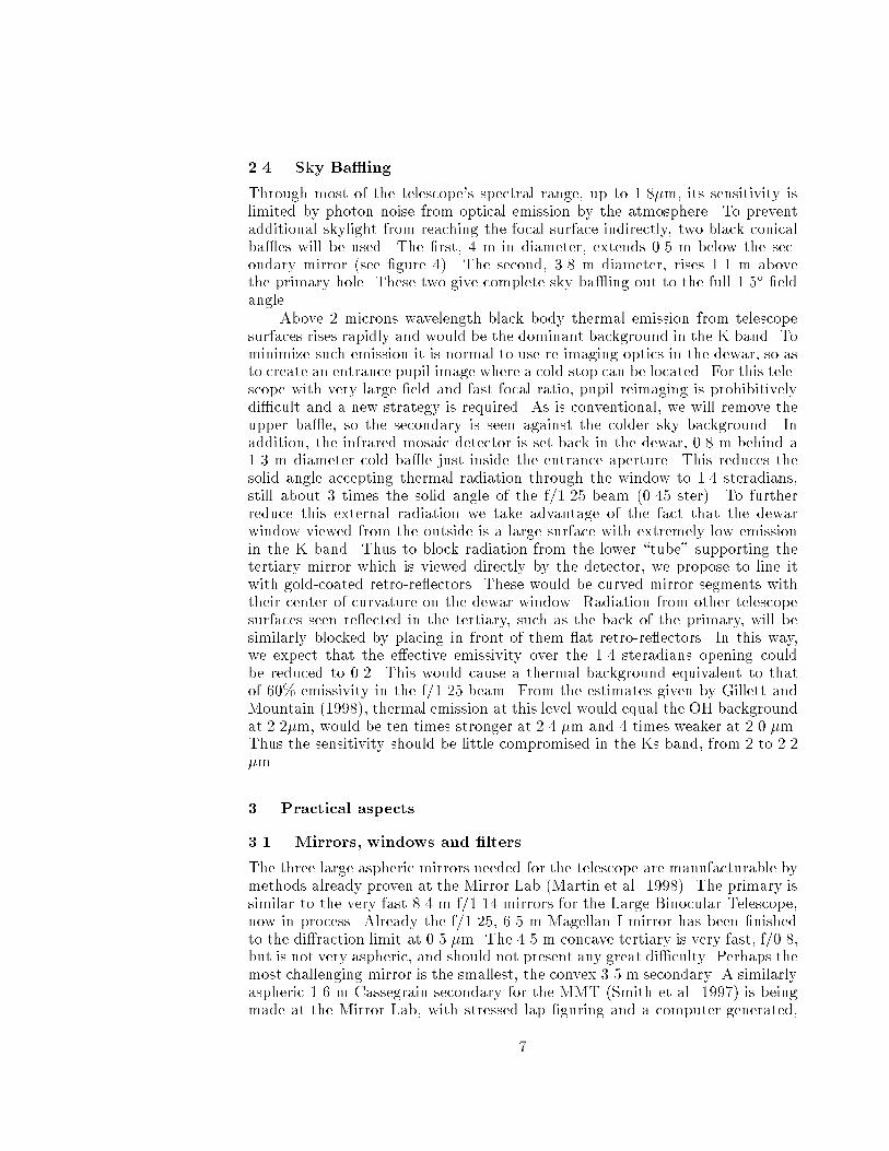
The optical assembly for an 8.4 m primary is short, only 9 meters betweenthe secondary and tertiary, with the primary and camera set midway between.This con�guration is advantageous both for making an agile telescope and aninexpensive enclosure. An ideal, alt-azimuth mount would be like that of theLBT (Hill & Salinari, 1998). All three large mirrors would be sti�y mountedbetween two C rings, supported on a compact azimuth frame that transmitsloads directly to a large diameter pier. This concept, developed by WarrenDavison, is illustrated in �gure 4. The sti�ness of the drives gains by the squareof the C ring radius, and we �nd that the large semicircular rings shown, 11 m
9
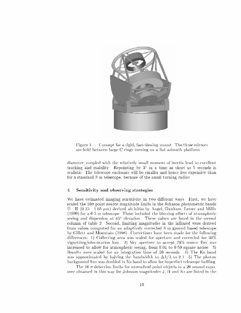
Figure 4. Concept for a rigid, fast-slewing mount. The three mirrorsare held between large C rings turning on a at azimuth platform.
diameter, coupled with the relatively small moment of inertia lead to excellenttracking and stability. Repointing by 3� in a time as short as 5 seconds isrealistic. The telescope enclosure will be smaller and hence less expensive thanfor a standard 8 m telescope, because of the small turning radius.
4. Sensitivity and observing strategies
We have estimated imaging sensitivity in two di�erent ways. First, we havescaled the 10� point source magnitude limits in the Johnson photometric bandsU - H (0.35 - 1.65 �m) derived ab-initio by Angel, Dunham, Lesser and Millis(1999) for a 6.5 m telescope. These included the blurring e�ects of atmosphericseeing and dispersion at 45� elevation. These values are listed in the secondcolumn of table 2. Second, limiting magnitudes in the infrared were derivedfrom values computed for an adaptively corrected 8 m ground based telescopeby Gillett and Mountain (1998). Corrections have been made for the followingdi�erences: 1) Collecting area was scaled for aperture and corrected for 30%vignetting/obscuration loss. 2) Sky aperture to accept 70% source ux wasincreased to allow for atmospheric seeing, from 0.01 to 0.50 square arcsec. 3)Results were scaled for an integration time of 20 seconds. 4) The Ks bandwas approximated by halving the bandwidth to ��=� to 0.1. 5) The photonbackground ux was doubled in Ks band to allow for imperfect telescope ba�ing.
The 10 � detection limits for unresolved point objects in a 20 second expo-sure obtained in this way for Johnson magnitudes J, H and Ks are listed in the
10
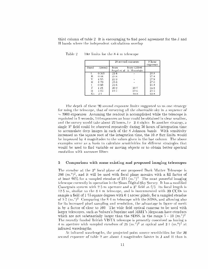
third column of table 2. It is encouraging to �nd good agreement for the J andH bands where the independent calculations overlap.
Table 2. 10� limits for the 8.4 m telescope.
20 second exposure 9 hourexposure
Band �(mm) from from GillettAngel et al & Mountain
U 0.365 22.8 - 26.8B 0.44 23.8 - 27.8V 0.55 23.9 - 27.9R 0.70 23.6 - 27.6I 0.90 22.8 - 26.8J 1.25 20.9 20.7 24.8H 1.65 19.5 19.6 23.5Ks 2.1 - 18.8 22.8
The depth of these 20 second exposure limits suggested to us one strategyfor using the telescope, that of surveying all the observable sky in a sequence of� 3000 exposures. Assuming the readout is accomplished while the telescope isrepointed in 5 seconds, 144 exposures an hour could be obtained in clear weather,and the survey would take about 22 hours, i.e. 3-4 nights. In another strategy, asingle 3� �eld could be observed repeatedly during 50 hours of integration timeto accumulate deep images in each of the 8 Johnson bands. With sensitivityincreased as the square root of the integration time, the 10 � ux limits wouldbe improved by 4 magnitudes to the values given in the last column. The aboveexamples serve as a basis to calculate sensitivities for di�erent strategies thatwould be used to �nd variable or moving objects or to obtain better spectralresolution with narrower �lters.
5. Comparison with some existing and proposed imaging telescopes
The etendue at the 3� focal plane of our proposed Dark Matter Telescope is260 (m:�)2, and it will be used with focal plane mosaics with a �ll factor ofat least 90% for a sampled etendue of 234 (m:�)2. The most powerful imagingtelescope currently in operation is the Sloan Digital Sky Survey. It has a modi�edCassegrain system with 2.5 m aperture and a 3� �eld at f/5. Its focal length is12.5 m, similar to the 8.4 m telescope, and is instrumented with 30 CCDs tosample a �eld of 1.55 square degrees with 0.4 arcsec pixels, for a sampled etendueof 5.7 (m:�)2. Comparing the 8.4 m telescope with the SDSS, and allowing alsofor its increased pixel sampling and resolution, the advantage in �gure of meritis by a factor of close to 100. The wide �eld optical cameras to be used withlarger telescopes, such as Subaru's Suprime and MMT's Megacam have etendueswhich are not substantially larger than the SDSS, in the range 5 - 10 (m:�)2.The recently funded British VISTA telescope is presently conceived as having a4 m aperture with sampled etendues of 28 (m:�)2 at optical and 3.1 (m:�)2 atinfrared wavelengths.
At infrared wavelengths, the projected point source sensitivities for the 20second exposure of table 2 are about 4 magnitudes fainter in J and H than is
11
being achieved by 2MASS (Cutri, 1999), and about 3.5 magnitudes at Ks. Thisimprovement is consistent with 40 times larger collecting area, 10 times sharperresolution (by solid angle) and 2.5 times longer integration time.
6. Spectroscopy with multiple integral �eld units
While the main function of the telescope will be imaging, it could be a valuabletool for spectroscopy. It has unique potential for spectroscopic follow up of rareobjects with a density of a few to a few hundred in the 3� �eld. A good examplemight be the few dozen supernovae with z � 1.5 found in one �eld. Because oftheir small �eld, standard 8 m telescopes could obtain spectroscopic redshifts ofonly one or two at a time.
The spectroscopic addition discussed by Angel et al, (1999) used small,individual units to reimage objects on the �bers at longer focal ratio. Theseunits incorporated small prisms, individually motorized for atmospheric disper-sion correction. Additional mechanisms corrected continuously for atmosphericanamorphic distortion of the rotating �eld. The system is thus somewhat com-plex, and there remain concerns that sky subtraction and coupling e�ciencywould prevent spectroscopy of the faintest sources.
An attractive alternative is to use multiple, small-scale integral �eld units.For example, individual �elds of 2 x 3 arcsec could be re-imaged onto 6 x 9lenslet arrays subtending 1/3 arcsec each, that would in turn form pupil imageson an array of 54 �ber ends. In this case no mechanisms are needed to correctfor either atmospheric dispersion or variable anamorphic distortion with �eldrotation. Images free from chromatic aberration would be reconstructed fromthe time sequence of dispersed spectra. The coupling losses in such systems canbe kept low, and accurate sky subtraction obtained at the level needed to studythe faintest galaxies. If the lenslets were sized at 1 mm, each coupler footprintneed be little larger than the 6 x 9 mm needed for lenslet array, and severalhundred units could be placed at once before crowding in the 2000 cm2 �eldwould become problematic.
Acknowledgments. We are grateful to Bob Millis, Peter Stritmatter, Sid-ney Wol� for their encouragement and interest in this concept. Reconsiderationof the Paul design was stimulated by the recent Lowell workshop on Kuiper beltobjects.
References
Angel, J. R. P., Dunham, T., Lesser, M. & Millis, R. 1999, preprint
Armandro�, T., Bernstein, G. M., Larsen, G., Millis, R. L. Pinto, P. A., Tyson,J. A., Wittman, D. M., & Zaritsky, D. F. 1999, preprint
R. Cutri 1999, 2MASS web page
Gillett, F.C. & Mountain, M. 1998, Science with the NGST, E.P. Smith and A.Koratkar eds, ASP Conf. Series 133, 42-51
Hill, J. M. & Salinari, P. 1998, Proc. SPIE, 3352, 23
12
Martin, H. M., Allen, R.G., Angel, J. R. P., Burge, J. H., Davison, W. B.,DeRigne, S. T., Dettmann, L. R., Ketelsen, D. A., Kittrell, W. C., Miller,S. M., Stritmatter, P.A., and West, S. C. 1998, Advanced TechnologyOptical/IR Telescopes VI, Proc. SPIE, 3352, 194-204
McGraw, J. T., Stockman, H. S., Angel, J. R. P., Epps, H. & Williams, J. T.1982, Proc SPIE, 331, 137
Paul, M. 1935, Rev d 'Optique, 14, 169
Smith, B.K., Burge, J.H., & Martin, H.M. 1997, Optical Fabrication and TestingII, Proc. SPIE, 3134
Tower, J. R. 1999, Proc. Inter. Conf. on Scienti�c Optical Imaging IV, M. B.Denton, editor, in press
Vural, K. 1999, private communication
Willstrop, R.V. 1984, MNRAS 210, 597 609
13