Embed Size (px)
Citation preview

Design, Fabrication, and Assembly of Small Wind Generator Test Benches
Institute for Sustainable Energy Solutions Derek Blash and Ben Rogowitz, Primary Contributors
Support provided by the Department of Energy (DOE) American Recovery & Reinvestment Act (ARRA) Grant DE-EE0003545

P a g e | 2
Table of Contents
I. Introduction ........................................................................................................................ 3
II. Mechanical Design .............................................................................................................. 3
A. Wind Generator .............................................................................................................. 3
B. Driving Motors ................................................................................................................ 4
C. Benches ............................................................................................................................ 5
D. Primary Mounting Components .................................................................................... 7
Large Test Bench ............................................................................................................. 7
Small Test Bench ............................................................................................................. 9
E. Mounting Hardware, Materials, and Associated Tools .............................................. 12
III. Electrical Components ..................................................................................................... 14
A. Large Test Bench, Parts and Electrical Wiring ........................................................... 14
B. Small Test Bench, Parts and Electrical Wiring ........................................................... 17
C. Construction and Programming .................................................................................. 21
IV. Manufacturing & Assembly ............................................................................................. 22
A. Large Test Bench .......................................................................................................... 22
B. Small Test Bench ........................................................................................................... 23
V. Operating the Test Benches ............................................................................................. 26
VI. Appendix A (Mechanical Schematics)............................................................................. 28
VII. Appendix B (Electrical Coding) ....................................................................................... 41
A. Program for LCD / rpm Display .................................................................................... 41
B. Program for Small Test Bench Motor Controller .......................................................... 42
VIII. Appendix C (Structural Analysis) .................................................................................... 45

P a g e | 3
I. Introduction The main objective of this project was to design, build, and test two small wind generator test benches that could be used in electrical and mechanical engineering classes to promote understanding of wind systems. One of the test benches was designed to be portable, allowing it to be used for outreach events. The parts and materials for each bench cost approximately $1000.
II. Mechanical Design
A. Wind Generator The wind generator chosen for this project was the Southwest Windpower Air-X model, a 400 W system which is primarily used to charge batteries in off-grid settings. The specifications for this system are shown in Figure 1. This system was chosen for its convenient size and safe power levels, along with its general availability and low cost (several hundred dollars). Although this system includes a circuit board for AC-DC conversion and safe battery charging, the intended curricular uses for the test bench involved the three-phase AC power produced directly from the permanent magnet generator. The generator’s rated power output occurred at approximately 1700 rpm.
Figure 1. Air-X wind generator specifications (windenergy.com).
P a g e | 4
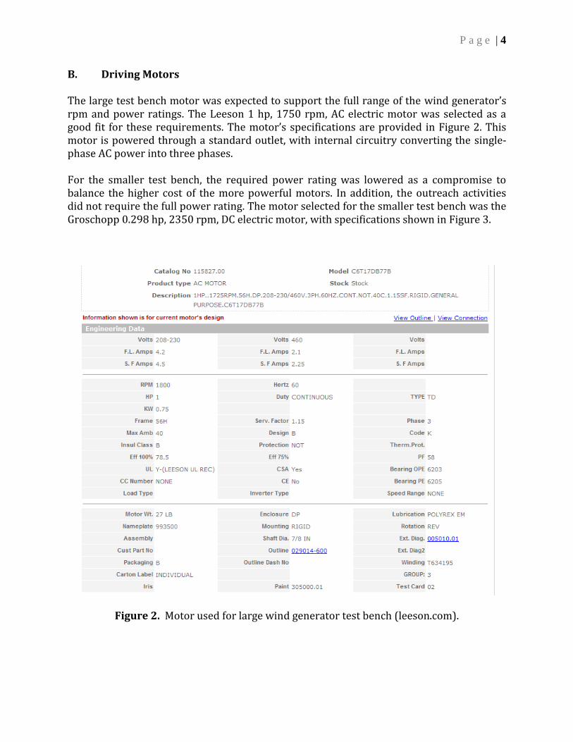
B. Driving Motors The large test bench motor was expected to support the full range of the wind generator’s rpm and power ratings. The Leeson 1 hp, 1750 rpm, AC electric motor was selected as a good fit for these requirements. The motor’s specifications are provided in Figure 2. This motor is powered through a standard outlet, with internal circuitry converting the single-phase AC power into three phases. For the smaller test bench, the required power rating was lowered as a compromise to balance the higher cost of the more powerful motors. In addition, the outreach activities did not require the full power rating. The motor selected for the smaller test bench was the Groschopp 0.298 hp, 2350 rpm, DC electric motor, with specifications shown in Figure 3.
Figure 2. Motor used for large wind generator test bench (leeson.com).

P a g e | 5
Figure 3. Motor used for portable wind generator test bench (groschopp.com).
C. Benches
The larger test bench had to support the weight of the wind generator and driving motor and had to be easily moved between classrooms. Extra surface area was desirable for test equipment, such as the oscilloscopes and load bank. A good compromise between these requirements, durability, and cost was found in the bench shown in Figure 4. Since the smaller test bench was intended for outreach along with the standard classroom activities, it needed to be small, lightweight, and mobile. The final choice was the bench shown in Figure 5, which was just big enough to fit the wind generator, driving motor, and an oscilloscope. The top surface was found to be too frail and was therefore replaced by a 40” x 24” piece of sanded plywood. This top piece had to be cut more precisely to the correct size and then coated in a polyurethane base wood finish to create a safe, durable surface.

P a g e | 6
FIXED HEIGHT BUTCHER BLOCK TOP MOBILE WORKBENCH
72" x 30" Safety Edge Ash Top, Stock No: WB579114A
Figure 4. Workbench used for large wind generator test bench (globalindustrial.com).
Figure 5. Workbench used for portable wind generator test bench (vistamation.com).

P a g e | 7
D. Primary Mounting Components
Large Test Bench
The large test bench’s motor had a rigid mount already attached, so only a base plate and a method to connect the generator needed to be designed. Since the motor shaft already had a keyway, the connecting device needed a keyway connection scheme. A direct helical shaft coupler with a 5/16” hex-head attachment at the end was chosen to connect the motor and generator (Figure 6). Figure 7 shows the fabricated hex-head adapter.
Figure 6. Helical shaft coupler used for the large test bench (heli-cal.com).
Figure 7. Hex-head adapter fabricated for the large test bench.
P a g e | 8
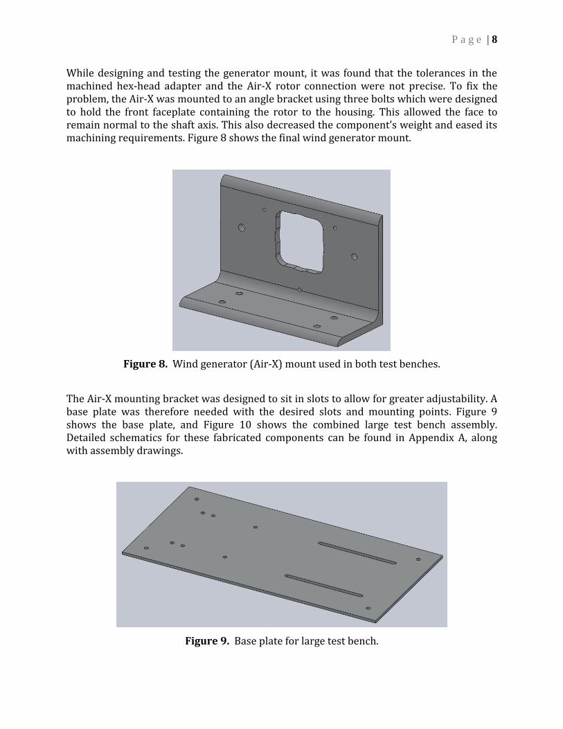
While designing and testing the generator mount, it was found that the tolerances in the machined hex-head adapter and the Air-X rotor connection were not precise. To fix the problem, the Air-X was mounted to an angle bracket using three bolts which were designed to hold the front faceplate containing the rotor to the housing. This allowed the face to remain normal to the shaft axis. This also decreased the component’s weight and eased its machining requirements. Figure 8 shows the final wind generator mount.
Figure 8. Wind generator (Air-X) mount used in both test benches.
The Air-X mounting bracket was designed to sit in slots to allow for greater adjustability. A base plate was therefore needed with the desired slots and mounting points. Figure 9 shows the base plate, and Figure 10 shows the combined large test bench assembly. Detailed schematics for these fabricated components can be found in Appendix A, along with assembly drawings.
Figure 9. Base plate for large test bench.

P a g e | 9
Figure 10. Large test bench mount assembly.
Small Test Bench
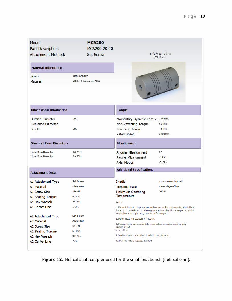
The small test bench’s motor had no mount, so a base plate, a motor mount, and a method to connect the motor to the generator were designed. The connection method was similar to that used for the large test bench, with different dimensions as appropriate while still allowing the wind generator to be swapped between the benches. This was made possible because the height for the shaft in the small test bench was chosen to be the same height as the large motor sitting on its stand. Figure 11 shows the fabricated hex-head adapter. Specifications of the direct helical shaft coupler are shown in Figure 12. The generator mount was the same as that for the large test bench, previously shown in Figure 8.
Figure 11. Hex-head adapter for the small test bench.
P a g e | 10
Figure 12. Helical shaft coupler used for the small test bench (heli-cal.com).

P a g e | 11
Next, the motor mounts were designed. Due to the awkward shape of the motor and its mounting points, two large angle brackets were machined to fit the face extrusions on the motor. This provided for a large amount of metal-to-metal contact while still allowing for the small shaft of the motor to be used. Figure 13 shows the angle bracket.
Figure 13. Angle bracket used to mount the small test bench’s motor.
The base plate for the small test bench, which contained the desired slots and mounting points, is shown in Figure 14. The complete mounting system for the small test bench is shown in Figure 15. Appendix A contains detailed drawings of these components, along with assembly drawings.
Figure 14. Base plate used for the small test bench.

P a g e | 12
Figure 15. Complete mounting system for the small test bench.
E. Mounting Hardware, Materials, and Associated Tools The following tools and equipment were used in fabricating some of the components listed in the previous sections and attaching all components together.
Mill Lathe Horizontal or vertical band saw with a minimum of 8.5 inches by 4.5 inches of
allowable cutting to occur Hand sander (preferably electric) Hand drill that fits 3/8” drill bit and 1” or greater diameter hole cutter 3/8” drill bit and end mill 5/16” drill bit 1/4” drill bit 3/16” end mill 13/32” drill bit preferably but 7/16” will work as well 3/4” drill bit 3/8” diameter fill and flat file 1” or greater diameter hole cutter Hexagon-a-diagonalizer (hexagonal collet) with collets to fit 1” diameter round
stock (a rotary table will do but will not be as accurate) Milling mini jacks to support material while in vise Polyurethane brushes Sand paper ranging from course to fine grain Set of Allen keys Large rotary saw Hand saw

P a g e | 13
Soldering iron Solder Wire cutters Wire strippers
Table 1 lists the materials and hardware used in fabricating and connecting the workbench components. Most of these parts were found at local hardware stores, and a few items were obtained on-line at McMaster-Carr. Assembly instructions are included in Appendix A. Table 1. Materials and hardware used in test bench fabrication and assembly.
Quantity Material / Hardware
2 24” x 12” x 1/4” 6061 multipurpose aluminum plate 1 4” x 6” x 48” 6061 multipurpose aluminum alloy angle bracket 1 1” diameter x 12” 7075-T651 high strength aluminum alloy round
stock 1 45” W x 25” D x 38” H mobile workbench w/ storage 1 72” W x 30” D ash mobile work bench – fixed height – 1 3/4” top 5 3/8” x 3” hex bolts (course 16) 4 3/8” x 2” hex bolts (course 16) 4 3/8” x 1.25” hex bolts (course 16) 8 3/8” x 1.25” carriage hex bolts (course 16)
12 3/8” nylon nuts (course 16) 5 3/8” wing nuts (course 16) 5 5/16” x 1” hex bolts (course 18) 1 5/16” x 3” hex bolts (course 18) 4 5/16” nylon nuts (course 18) 8 1/4” x 1.5” hex bolts (course 20) 4 1/4” nylon nuts (course 20) 8 4-40 x 3/4” steel flat head Phillips bolts 8 4-40 brass nut 8 6-32 thread 1/4” OD x 1/2” length nylon spacers 1 3/16” x 1.25” square keyway (material?) 4 6 x 1 flathead Phillips head wood screws 8 3/8” x 2” flat washers 8 3/4” flat washers 3 10 – 24 x 2” threaded bolts (fine 24) 6 3/16” ID flat washers 1 Polyurethane wood finish (1 quart) 1 Polyester brushes (wide) 1 5-min. epoxy 1 40” W x 24” D sanded handy panel, pine, plywood 1 11/16” x 11/16” x 40 1/3” stained wood trim

P a g e | 14
III. Electrical Components
A. Large Test Bench, Parts and Electrical Wiring
The larger test bench has a 1 hp motor that uses three-phase power. The motor’s controller converts the single phase AC signal from the wall outlet into the necessary three phases. The controller does display a frequency in Hz, but this frequency does not represent the motor’s rotational frequency - it represents the electrical frequency that is fed into the motor. Therefore, an external rpm detection circuit is needed. Note that the controller can also display the current, voltage, and power that are input to the motor. This data may be used to calculate the efficiency of the entire system. The parts used in the electrical control and rpm display for the large test bench are shown in Table 2. The wiring diagram for connecting the controller to the motor is shown in Figure 16, and a physical example of this wiring is shown in Figure 17, where the white cable is connected to a wall outlet and the black cable is run to the motor. Figure 18 presents the wiring diagram for the rpm display, and Figure 19 shows an example implementation of this circuit, where the axial capacitor is smoothing the input 9 Vdc signal. A strong magnet is placed on the rotating shaft to trigger the Hall Effect sensor (see, for example, Figure 23).
Table 2. Electrical components used in the large test bench.
Description Part Number Source Motor controller (for Leeson motor) WGB222386 globalindustrial.com Hall effect sensor AH375-PL-A mouser.com TI microcontroller MSP430F2012IN “ “ TI launch pad development kit MSP-EXP430G2 “ “ Newhaven display NHD-0216K3Z-NSW-BBW “ “ 3.3 V line regulator LD1117V33 “ “ 5 V line regulator LM7805CT “ “ 4.7 uF, 50 V axial capacitor 74-150D475X9050B2BE3 “ “ 9 V adapter / power supply 826-DA4-110US “ “

P a g e | 15
Figure 16. Electrical wiring diagram for the large test bench motor and controller.
Figure 17. Example wiring of the large test bench controller.

P a g e | 16
Figure 18. Electrical wiring diagram for the large test bench rpm display.
Figure 19. Example circuit used for the large test bench rpm display.
Newhaven display
To Hall Effect
Sensor
Voltage
Regulators
From 9V
Adapter
Microcontroller
Smoothing
Capacitor

P a g e | 17
B. Small Test Bench, Parts and Electrical Wiring
The motor controller for the small bench was designed to be user friendly and safe. This was achieved by using a microcontroller to regulate the motor’s speed by adjusting the pulse width (i.e., duty cycle) input to the motor driver, as seen in the electrical schematic in Figure 20. The microcontroller was a Texas Instruments MSP430. There are three inputs to this controller: rpm, a speed-up button, and a slow-down button, as shown in Figure 21 and Figure 22. The processor receives information from a Hall Effect sensor that toggles every time a magnet passes the sensor as the motor shaft spins (see Figure 23). The processor calculates an average from ten toggles and uses the average period to calculate an rpm value. Based on the rpm set-point, the processor will either increase the duty cycle input to the motor driver if the rpm is too low or decrease the duty cycle if the motor is spinning too fast. There is also a second controller which calculates the rpm and outputs the value onto a serial RS232 character display. The reason that the first controller is not handling both functions is a lack of timers in the controller; there is only one timer on each controller, and it is not capable of handling both jobs. The power side of this project consists of running 120 Vac from a standard power outlet into a transformer to get 24 Vac, as shown in Figure 24. When rectified, the voltage is roughly 34 Vdc. A filter capacitor is used to reduce the ripple. The 34 Vdc power is fed into the motor driver, which will take the 3.3 V output voltage of the microcontroller and amplify it to 15 V to run the gates on the MOSFETs. The microcontroller will run the MOSFETs and will change their duty cycle. This will control how much power is allowed into the motor in order to regulate its speed. The start and stall current of the motor is 66 Amps, and the peak current of the motor driver is 75 Amps, but the motor will never start under full power. Under normal operations the current should be no more than 14 Amps, and the motor driver is rated for 20 Amps of continuous current. The transformer will need to handle about 500 Watts at 24 Vac. The filter capacitor reduces the ripple from the rectified 24 Vac, which helps the controller to provide constant power to the motor. If the motor is running at 12 Amps, the voltage ripple is 5%. The various electrical components used for the small test bench are listed in Table 3.

P a g e | 18
Figure 20. Electrical wiring diagram for the small test bench.

P a g e | 19
Figure 21. Example small test bench circuit configuration.
Figure 22. Example small test bench switch configurations.
MSP430 for
Motor Driver
Voltage
Regulators
Cable to
Pushbuttons
Motor Driver
Board
MSP430 for
RPM Calc
Cable to RPM
Display
From 9V
Adapter
From 24 V
Supply
Output Motor
Power & White
Hall Effect Cables
To and From
Reset Switch
Pushbuttons with
102J Capacitors
Reset Button
LCD Display for
RPM Value

P a g e | 20
Figure 23. Example installation of Hall Effect sensor on small motor shaft.
Figure 24. Example power supply for the small test bench motor (housed inside bench).
Input Power from
Standard 120 Vac
60 Hz Outlet
Two Sets of 24
Vdc Output Cables
Output from
Smoothing
Capacitor goes to
Motor Switch /
Circuit

P a g e | 21
Table 3. Electrical components used in the small test bench.
Description Part Number Source Motor controller (for Groschopp motor) (Pololu 36V 20 motor driver)
1457 pololu.com
MSP430F2012 MSP430F2012IN mouser.com MSP430F2013 MSP430F2013TN “ “ TI launch pad MSP-EXP430G2 “ “ Newhaven display NHD-0216K3Z-NSW-BBW “ “ Hall effect sensor AH375-PL-A “ “ 3.3 V line regulator LD1117V33 “ “ 5 V line regulator LM7805CT “ “ 9 V adapter / power supply 826-DA4-110US “ “ 4.7 uF, 50 V axial capacitor 74-150D475X9050B2BE3 “ “ Motor switch (reset switch) 655-W51-A161A1-15 “ “ 100000 uF, 40 V capacitor 75-36DY104F040DC2A “ “ 120 VAC – 24 VDC transformer TE60603-ND digikey.com Example pushbuttons SW-780030, SW-780035 homeatswift.com 102J (1000 pF) capacitor for pushbuttons CD18FD102J03F-ND digikey.com
C. Construction and Programming When soldering the circuit together, make sure that the MSP430 is in a socket, as it will need to be removed. Programming Instructions
1. Install the Texas Instruments Code Composer Studio 4, using this link:
http://processors.wiki.ti.com/index.php/Download_CCS
You will need to register the software with Texas Instruments before installation.
2. Go to File > New > CCS Project
a. Call your project either Motor Controller (for the large test bench) or LCD
Rpm (for either bench).
i. Click “Next” until you get to a screen called Project Setting.
ii. In the subsection “Device Variant” select the MSP430 that you are
programming (the MSP430f2013 for the motor controller or the
MSP430f2012 for the LCD display).
iii. Press finish.
3. Go to File > New > Source File
a. Paste in the appropriate program from Appendix B.
b. If you decide to have more magnets on the motors’ rotor, you will need to
change the divisor in the program.

P a g e | 22
4. Plug in the TI Launch Pad.
5. Press the debug button.
6. Take the chip out and install it into the circuit board.
IV. Manufacturing & Assembly Once the materials have been obtained, manufacturing and assembly can begin. Basic instructions for manufacturing and assembling the test benches are included below. If you do not have access to a fabrication shop or are not proficient in the use of the machinery necessary to complete these parts, take the mechanical schematics from Appendix A to a certified machinist for fabrication. A. Large Test Bench Large Work Bench To begin building this test bench, it is recommended to first decide where the testing assembly should be placed. Once a location has been chosen, drill the hole configuration into the butcher block. Then flip the butcher block over and drill the hole pattern for the leg mounting points. Next, coat the butcher block in the polyurethane gloss finish using the polyester brushes. Two thick coats should be enough to finish the butcher block for regular student use. After the butcher block has finished drying, the legs can be screwed onto the butcher block. The stiffening rear support can then be attached and the wheels can be added. Air-X Angle Brackets To attach the Air-X generator, use either the three 10 – 24 x 2” bolts or the 5/16” x 1” and 3/8” x 3.5” hex head bolts and the one of the 3/8” wing nuts and with the device in place, screw the bolts into their associated holes so that the bracket holds the device’s shaft parallel to the bottom surface. Test Bench/Base Plate Mounting Once the generator’s angle bracket has been assembled, it and the motor can be fastened to the base plate. Using four 3/8” x 1.25” carriage bolts and four 3/8” wing nuts, secure the angle bracket. This can be done easily right side up or upside down. However, when it comes to mounting the Leeson motor to the base plate, it is recommend that this be performed with the motor upside down and the base plate being mounted on top of it. Use four 5/16” x 1” hex head bolts and four 5/16” nylon nuts to secure the base to the motor.

P a g e | 23
B. Small Test Bench
Small Work Bench To assemble the small test bench, it is advised to begin with the mobile workbench purchased from Vistamation. This is not difficult since the wheels are the only parts that need to be attached to the body. The difficulty occurs in the need for the top of the work bench to have four holes at specific points corresponding to the hole configuration of the small test bench base plate. This requires separating the work surface from the storage area and then drilling through the thin steel. It is recommended to clamp the hand panel on top of the surface before the holes are drilled so that when the holes are drilled in the panel and the thin steel, they are aligned with each other.
Once this is complete, do not reattach the work surface. The reason will become apparent once the base plate is mounted. Another hole must be drilled into the main shelving panel to allow the capacitor to be mounted. A much larger hole must also be drilled into the side of the large storage area. This will serve as a hole for the electronics’ power cords to pass through and attach to the power strip on the other side that will be adhesively stuck to the outside (see Figure 25). Once these things have been completed, the capacitor, transformer, and power strip can be mounted (see Figure 24 for the transformer configuration). The transformer is mounted using a 5/16” x 3” hex head bolt and corresponding nylon nut. The others are held in place by 5 min. epoxy. This would also be a good time to sand and finish the handy panel. Two coats of the polyurethane are plenty for this application.
Figure 25. Power strip and cable run for small test bench.

P a g e | 24
Motor Mount To assemble the motor and its motor mounts, use the eight 1/4” x 1.5” bolts and corresponding nylon nuts to fasten them to each other through their corresponding holes. Air-X Angle Brackets To attach the Air-X generator, use either the three 10 – 24 x 2” bolts or the 5/16” x 1” and 3/8” x 3.5” hex head bolts and one of the 3/8” wing nuts. With the device in place, screw the bolts into their associated holes so that the bracket holds the device’s shaft parallel to the bottom surface. Test Bench/Base Plate Mounting Once the motor mount and the generator’s angle bracket are assembled, the two can be mounted to the base plate. Begin by placing the motor mount on a flat, sturdy surface upside down so that the flat surface that sits on the base plate is facing upward. Then place the base plate on top of it so that the bolt holes corresponding to the motor mount are concentric. Then use four of the 3/8” x 1.25” hex-head bolts and four of the 3/8” nylon nuts to secure the motor to the base plate by placing the bolts through the concentric holes and tightening down the nylon nut on the opposite side so that the base plate and the motor mount is sandwich between the bolt head and the nut. Perform this for all four mounting points and then check to make sure that the mount is indeed secure. Once the mount is in place, the generator’s angle bracket can be attached. Complete this task just as you did before, except use four of the 3/8” x 1.25” carriage bolts and 3/8” wing nuts. Once both mounts are secure, flip the assembly over. The entire assembly can now be mounted to the work surface of the workstation. Begin by placing the dried handy panel on top of the work surface so that the hole pattern in the wood aligns itself with the hole configuration in the steel. Then perform the same task for the base plate assembly. Using the four 3/8” x 2” hex-head bolts and four 3/8” nylon nuts, fasten the base plate assembly, handy panel, and work surface to each other so that nothing moves. This can be done by passing a bolt through the concentric hole patterns in each part and tightening the nylon nut down to a tight fit. Once these parts are secured to each other, they can be resecured to the storage sections of the work bench. Electrical Mounting Once the bench has been assembled to a near finished state, the electrical components can be attached. The electrical enclosure with the clear screen should be mounted first. Using the four wood screws, screw the electrical box down through the mounting points near the corners of the enclosure. The final test bench configurations are shown in Figure 26 and Figure 27.

P a g e | 25
Figure 26. Completed large test bench configuration.
Figure 27. Completed small test bench configuration.

P a g e | 26
V. Operating the Test Benches This section contains instructions on how to operate the small and large test benches. A. Large Test Bench
Turn On
1. Plug the power strip into the wall.
2. Turn the power strip switch to the “on” position.
3. Check the LCD display; it should be glowing blue.
Change the Motor / Generator Speed (The controls mentioned below are located on the motor controller.)
1. Make sure that the potentiometer is turned all the way counter-clockwise.
2. Press the green run button.
3. Turn the potentiometer clockwise to increase the motor speed.
4. Turn the potentiometer counter-clockwise to slow the motor down.
5. If you want to see the power that the prime mover is using, press the func
button, and you will see the current, voltage, power and electrical Hz of the
motor.
Turn Off 1. Press the red stop button till the motor comes to a stop.
2. Press the power strip button to turn it off.
3. Unplug the power strip from the wall.
Note: The controller does take a minute to turn off B. Small Test Bench
Turn On
1. Plug the power strip into the wall.
2. Turn the power strip switch to the on position.
3. Check the LCD display; it should be glowing blue.
4. Turn the motor power switch on the display box.
Change the Motor / Generator Speed 1. To make the motor speed up by 100 rpm, press and release the red button once.
2. To make the motor slow down by 100 rpm, press and release the black button
once.
Note: The response time of the PID controller is slow when the rpm is low.

P a g e | 27
Turn Off 1. Press and release the black button repeatedly, until the motor comes to a stop.
2. Turn the power off to the motor.
3. Press the power strip button to turn it off.
4. Unplug the power strip from the wall.

P a g e | 28
VI. Appendix A – Mechanical Schematics A. Small Test Bench Assembly

P a g e | 29
B. Large Test Bench Assembly

P a g e | 30
C. Groschopp 0.3121 Hp 2400 rpm Motor Dimensions

P a g e | 31
D. Leeson 1.5 Hp 1800 rpm Motor Dimensions

P a g e | 32
E. Groschopp Motor Mount
P a g e | 33
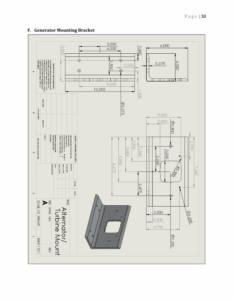
F. Generator Mounting Bracket

P a g e | 34
G. Small Helical Coupler

P a g e | 35
H. Large Helical Coupler (Without Keyways)

P a g e | 36
I. Small Hex-head Adapter

P a g e | 37
J. Large Hex-head Adapter

P a g e | 38
K. Small Bench Base Plate

P a g e | 39
L. Large Bench Base Plate

P a g e | 40
M. Electronics Face Plate

P a g e | 41
VII. Appendix B – Microcontroller Programs A. Program for LCD / rpm Display
int count = 0; int lastcount = 0; int revolutions = 0; float rpm = 0; long Time = 0; int To = 0; int rev = 0; long Timmer; #include "msp430f2012.h" // Pins on the MSP430 we're using #define TXD BIT1 // TXD on P1.1 #define BUTTON BIT3 // Button on P1.3 // Conditions for 9600 Baud SW UART, SMCLK = 1MHz #define Bitime 13 // 1,000,000 / 8 / 9600 = ~13 // variables for serial communication unsigned char BitCnt; unsigned int TXByte; unsigned int buttonPresses = 0;// function prototypes void TXString(char *string); void ConfigureTimerUart(void); void Transmit(); void brag(void); void itoa(unsigned int val, char *str, unsigned int limit); void main( void ) { // Stop watchdog timer to prevent time out reset WDTCTL = WDTPW + WDTHOLD; // Set clock to 1MHz, and SMCLK to 125kHz BCSCTL1 = CALBC1_1MHZ; DCOCTL = CALDCO_1MHZ; BCSCTL2 &= ~(DIVS_3); //SMCLK is DCO/8 // Set up the timer to simulate a UART ConfigureTimerUart();

P a g e | 42
P1DIR |= 0x02 + 0x40 + 0x80; P1OUT |= 0x01; P1REN |= 0x01; // wait for LCD display to initialize __delay_cycles(1000000); __enable_interrupt(); B. Program for Small Test Bench Motor Controller
#include <msp430f2013.h> int TARGET = 100; int count = 0; int lastcount = 0; int revolutions = 0; float rpm = 0; int PWM = 0; long constant = 2425000; unsigned long Time = 0; int buttonup; int lastbuttonup = 1; int buttondown; int lastbuttondown; void TimerPwm(void); void main(void) { WDTCTL = WDTPW + WDTHOLD; // Stop Watch Dog Timer BCSCTL1 = CALBC1_16MHZ; // Set Clock speed to 16Mhz DCOCTL = CALDCO_16MHZ; P1DIR |= 0x04 + 0x01 + 0x02; // Set output pins P1OUT = 0x08 + 0x40 + 0x80; P1REN |= 0x08 + 0x40 + 0x80; // Button pin state change for (;;) { if(TARGET >= 400) P1OUT |= 0x02; if(TARGET < 400) P1OUT &= ~0x02; TimerPwm(); if (0x80 & P1IN){ buttondown = 1;

P a g e | 43
} else{ buttondown = 0; } if (buttondown != lastbuttondown){ if (buttondown == 1){ TARGET = TARGET - 100; _delay_cycles(8000000); if (TARGET < 100){ TARGET = 100; PWM = 0; } } lastbuttondown = buttondown; } if (0x40 & P1IN){ buttonup = 1; } else{ buttonup = 0; } if (buttonup != lastbuttonup){ if (buttonup == 1){ TARGET = TARGET + 100; _delay_cycles(8000000); if (TARGET > 1700){ TARGET = 1700; } } lastbuttonup = buttonup; } // rpm detection with debounce if (0x08 & P1IN){ count = 1; } else{ count = 0; } if (count != lastcount){ if (count == 1){ revolutions++; }
P a g e | 44
lastcount = count; } if (Time > 160000 && TARGET == 200) PWM = 400; // motor controll using increments if (revolutions >= 1) { rpm = constant/Time; rpm = rpm * 3; revolutions = 0; Time = 0; if (rpm > TARGET){ PWM = PWM - 1; } if (rpm > TARGET-10 && rpm < TARGET){ PWM = PWM + 1; } if (rpm > TARGET-25 && rpm < TARGET-10){ PWM = PWM + 1; } if (rpm < TARGET-25 && rpm > TARGET-100){ PWM = PWM + 2; } if (rpm < TARGET-100){ PWM = PWM + 5; } if (PWM >= 550){ PWM = 550; } if (PWM < 0){ PWM = 0; } } } } // PWM timer void TimerPwm(void) { Time ++; P1SEL |= 0x04; CCR0 = 700; // PWM Period CCTL1 = OUTMOD_7; // CCR1 reset/set CCR1 = PWM; // CCR1 PWM duty cycle TACTL = TASSEL_2 + MC_1; // SCLK, up mode / Clock Divide by 2 }

P a g e | 45
VIII. Appendix C – Structural Analysis This section explains the structural analysis performed for this project. A. Mechanical To verify the design and materials chosen for the Air-X test benches, an analysis was conducted to demonstrate that nothing in the test bench would fail structurally in a worst-case scenario. The analysis was performed with the SolidWorks Simulation finite element software, and the von Mises failure criteria were used to check for any yielding that may occur. It is also important to note that no analysis was performed on any fixtures such as the base plate, bolts, screws, or adhesive due to their high yield strength and/or lack of excessive loading applied to them. 1. Helical Couplers The connection point between the motor and the Air-X generator undergoes cyclic loading due not only to the coupler and the shaft being misaligned but also because of the load that is transferred through the system. Each coupler is designed to handle the expected torque and misalignment; however, analysis was still completed to verify that the connections between the machined parts and the coupler would not fail in extreme cases. Below are the calculations and analysis performed for this particular area. Small Test Bench Coupler The small test bench helical shaft coupler is held in position by two set screws 120 degrees apart from each other. However, the Groschopp motor has a D shaft of hardened steel. Therefore, only one set screw can be tightened down onto a flat surface on the shaft, and the other must be tightened down to sit on the rounded surface. This is not true for the hex head adapter because the shaft is machined to have two flat surfaces. However, upon speaking with an applications engineer from Heli-Cal products, it was verified that the product would slip no earlier than 82 lb. in. of non-reversing torque and 164 lb. in. of momentary dynamic torque for either a flat or curved shaft as long as the setscrews for the product are tightened down to their seating torque of 65 lb. in. Set Screw Hex-head Adapter Analysis The set screw adapter, when under full load, sees large amounts of stress that can cause failure. However, this particular part was not designed to be fully loaded as the motor rating did not reach the generator’s full rating (the motor was undersized due to this test bench being used for outreach purposes). After performing multiple different analyses on this part, it was determined that the part will indeed catastrophically fail when a torque equal to the stall torque is applied. This is why the hex-head adapter is somewhat smaller than the hex cutout in the generator. The larger tolerance on the hex-head will allow, if need be, the corners of the hex extrusion to be sheared off in the enclosed area. This will prevent any shrapnel from flying away from the test bench and towards anyone nearby in the rare case of catastrophic failure. There are also safeguards in the generator itself. Even

P a g e | 46
when its leads are shorted, it will not come to a complete stop. This means that the worst-case scenario - with the generator coming to a sudden and complete stop - has essentially no chance of happening. This hypothesis was tested multiple times and yet no failure occurred. The simulation of the stress on the set screw hex-head adapter is shown in Figure 28.
Figure 28. Stress on the small test bench set screw adapter, maximum dynamic torque.
Large Test Bench Coupler The large test bench helical shaft coupler is held in position by a keyway that is cut into the coupler and the motor shaft. Another set of keyways is also cut into the other side of the coupler and the hex-head adapter. A steel and aluminum key is placed at these two points and is designed to fail if too much torque is exerted through the shaft. Since the shaft material and the included key are much stronger than the key on the opposite side, failure will actually occur at this keyway specifically.

P a g e | 47
Motor Shaft Keyway The key provided with the Leeson motor is a standard key, most likely 1020 steel. However, after contacting Leeson about the exact material properties, no final answer was obtained. In either case, the motor shaft key has a yielding strength less than both the 7075-T6 aluminum and the hardened steel shaft protruding from the motor. Hex-head Adapter Keyway Knowing that the adapter is made of an 7075-T651 aluminum alloy (yield strength of 66,000 psi) and the key being made of, most likely, a soft aluminum (Ace Hardware is unsure of the material the key is made of), it can be safely stated that the key will fail long before the stresses in the hex-head adapter become too great and failure occurs. Hex-head Adapter Analysis The adapter sees high amounts of stress when under the loading of the Leeson motor. It is actually so high that there are very few inexpensive, corrosive resistant materials that can handle this load, especially due to the sharp edges present near the hex-head. Unfortunately, there are even fewer materials capable of being machined to the necessary shape. However, because the generator won’t come to a complete stop as stated in the previous section, the hex-head adapter actually only has to handle the torque exerted by the motor if the load is suddenly increased by a factor of about two. The analysis of the hex-head adapter under the Leeson stall-torque is shown in Figure 29. As stated previously, the adapter is made of a high-strength, corrosive resistant aluminum alloy. However, even this material cannot handle the momentary dynamic torque created by the Leeson motor. This is one of the downsides of this design but it is compensated for by the key and set screw holding the hex-head adapter in place. If the motor were to fail, the set screw and key would fail before the hex-head adapter reaches its yielding point. However, if something were to prevent the key from failing, the corners of the hex-head would shear off. These corners would shear off inside of the hex-head extruded cut. This provides an enclosed area that will prevent metal from flying away from the bench. It is also important to note that this is the worst possible case scenario, but with the understanding that the generator will not cause the motor to stop completely, this design will never fail unless it is purposefully sabotaged.

P a g e | 48
Figure 29. Stress on the large test bench hex-head adapter, maximum dynamic torque.
2. Small Test Bench Motor Mount To analyze the Groschopp motor mount, a factor of safety of two was applied to the maximum stall torque possible (80 lb-in.) and then this loading was applied multiple times to the angle bracket. The first loading case was applying the chosen torque to all of the motor mounting points. This would simulate a best case scenario if the motor applied this kind of torque. Figure 30 shows the resulting stresses present in the motor mount.

P a g e | 49
Figure 30. Stresses in small test bench motor mount under stall torque loading conditions
applied to all mounting points.
This motor mount is made of 6061 - T6 multipurpose aluminum alloy. Its yielding strength is ~35,000 psi. However, with the current loading applied to it, the maximum stress reached in the material is 222.3 psi. Therefore, the angle bracket can handle more than twice the stall torque when the load is distributed between the four mounting points. Another study was conducted to see if the motor mount would fail when all the above discussed loading was put on one mounting point. Figure 31 shows those results. Even with the increase in loading at a single point, the maximum stress present in the angle bracket is far less than the yielding point of the material.

P a g e | 50
Figure 31. Stresses in Groschopp motor mount under stall torque loading conditions
applied to one mounting point.
3. Air-X Generator Mount, Driven by Smaller Motor To analyze the generator’s mount, the same procedure performed for Groschopp motor mount was used. First, twice the maximum stall torque (160 lb-in.) was applied to all of the mounting points for the Air-X generator. Figure 32 shows the result. As with the motor mount, this loading failed to cause any stress values above the yield limit of the material. Once no yielding was found in the perfect loading case, an anti-symmetric load was applied as it was for the motor mount. Figure 33 shows these results. Again, the material did not yield and therefore, it can be stated that the generator mount will not fail structurally while the test bench is use.

P a g e | 51
Figure 32. Air-X generator mount under Groschopp stall torque loading conditions applied
to all mounting points.

P a g e | 52
Figure 33. Air-X generator mount under Groschopp stall torque loading conditions applied
to one mounting point.
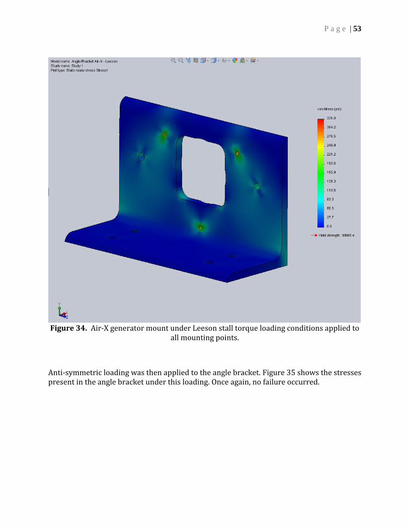
4. Air-X Generator Mount, Driven by Larger Motor The large test bench is very similar to the small test bench except the motor already has a built in mount. Therefore, only the angle bracket for the Air-X generator needed to be analyzed. The bracket was made of the same material as the angle bracket used in the small test bench and therefore had the same material properties. To analyze the effects that the additional strength of Leeson motor had on the angle bracket, a factor of safety of 2 was applied to the maximum stall torque possible (168 lb-in.) and then this loading was applied multiple times to the angle bracket. The first loading case was applying the chosen torque to all of the motor mounts. This would simulate a best case scenario if the motor applied this kind of torque. Figure 34 shows the stresses present in the angle bracket under symmetric loading about the shaft center. The analysis once again indicated absolutely no failure in the bracket.
P a g e | 53
Figure 34. Air-X generator mount under Leeson stall torque loading conditions applied to
all mounting points.
Anti-symmetric loading was then applied to the angle bracket. Figure 35 shows the stresses present in the angle bracket under this loading. Once again, no failure occurred.

P a g e | 54
Figure 35. Air-X generator mount under Leeson stall torque loading conditions applied to
one mounting point.