Embed Size (px)
Citation preview
DESIGN CRITERIA
CONSIDERED IN THE REVIEW OF
WASTEWATER TREATMENT FACILITIES
POLICY 96-1
COLORADO DEPARTMENT OF PUBLIC HEALTH and ENVIRONMENT Water Quality Control Commission
4300 Cherry Creek Drive South Denver, CO 80246-1530
ADMINISTRATIVE ACTION HEARING: April 9, 2007 EXPIRATION DATE: May 31, 2008
COLORADO DEPARTMENT OF PUBLIC HEALTH and ENVIRONMENT Water Quality Control Commission 4300 Cherry Creek Drive South Denver, CO 80246-1530
EXPLANATORY STATEMENT REGARDING UPDATES
DESIGN CRITERIA CONSIDERED IN THE REVIEW OF WASTEWATER TREATMENT FACILITIES
The attached "design criteria" for domestic wastewater treatment facilities are a composite of parts of previous criteria published June, 1973, the revised portions of the "Criteria used in the Review of Wastewater Treatment Facilities" approved by the Water Quality Control Commission on January 2, 1979 and updated in 1996, and modifications based on the outcome of a stakeholder process including the Water Quality Control Division, consulting design engineers and facility owners conducted from September 2001 to March 2002. The document allows the design engineer to be familiar with the criteria the State utilizes to review wastewater treatment facility designs.
II
REFERENCES References that may also be helpful to users of this document are:
Design of Municipal Wastewater Treatment Plants, MOP 8, 4th Edition, Water Environment Federation (WEF), 1998
Wastewater Engineering, Metcalf and Eddy, 3rd Edition, 1991
Municipal Wastewater Stabilization Ponds, EPA 625/1-83-015, October 1983, http://www.epa.gov/cgi-bin/claritgw?op-Display&document=clserv:epa-cinn:3911;&rank=1&template=epa
Alternative Wastewater Collection Systems, EPA 625/1-91/024, October 1991, http://www.epa.gov/cgi-bin/claritgw?op-Display&document=clserv:epa-cinn:2752;&rank=4&template=epa
Constructed Wetlands Treatment of Municipal Wastewaters, EPA 625/R-99/010, September 2000, http://www.epa.gov/cgi-bin/claritgw?op-Display&document=clserv:epa-cinb:1123;&rank=4&template=epa
Hammer, Donald, A., Constructed Wetlands for Wastewater Treatment: Municipal, Industrial and Agricultural, December 1989
Land Treatment of Municipal Wastewater: Process Design Manual, EPA 625/1-91-013, October 1981, http://www.epa.gov/cgi-bin/claritgw?op-Display&document=clserv:epa-cinn:2542;&rank=1&template=epa
Wastewater Treatment/Disposal for Small Communities, EPA 625/R-92/005, September 1992, http://www.epa.gov/cgi-bin/claritgw?op-Display&document=clserv:epa-cinn:2754;&rank=4&template=epa
Rich, Linvil Gene, High-Performance Aerated Lagoon Systems, American Academy of Environmental Engineers, December 1998
Tchobanoglous, George (Editor), Wastewater Engineering: Treatment and Reuse, 4th Edition, 2002
WEF, Alexandria, Virginia, Biological and Chemical Systems for Nutrient Removal, 1998
Henze, M., Herremoes, P., La Cour Jansen, J. and Arvin, E., Wastewater Treatment - Biological and Chemical Processes, 3rd Edition, 2002
III

Oswald, William J., Wastewater Treatment with Advanced Integrated Wastewater Pond Systems and Constructed Wetlands - ASCE (A syllabus on Advanced Integrated Pond Systems), 1996
IV

GENERAL STATEMENT
DESIGN CRITERIA CONSIDERED IN THE REVIEW OF WASTEWATER TREATMENT FACILITIES
The General Assembly of the State of Colorado has enacted certain laws relating to the pollution of streams and waters within the State of Colorado and has granted specific and general powers to the Colorado Water Quality Control Commission. The Commission, after public hearings, adopts and promulgates reasonable quality standards for State waters to prevent, control, and abate pollution. It is the responsibility of the operating agency to provide treatment facilities as required to meet the discharge permit limits which are based on the adopted water quality standards. The Colorado Department of Public Health and Environment, Water Quality Control Division (Division), by review of plans and specifications, assumes no responsibility for the successful operation of the facility so reviewed. It is the primary responsibility of the professional engineers designing such facilities as well as the agency constructing and operating such facilities to see that they will operate satisfactorily. The Colorado Water Quality Control Division must and will strictly enforce the provisions of State laws and regulations and discharge permit requirements. This publication provides technical guidance to Division staff on which to base the official review of plans and specifications involving wastewater treatment facilities designs. This document lists and suggests limiting values for items upon which the Division will make an evaluation of such plans and specifications. The official Division review is limited to the review of plans and specifications of new interceptors (greater than or equal to 24 inches in diameter), all domestic wastewater treatment facilities and wastewater pumping stations (Ref: 25-8-702 C.R.S.). An official review of plans and specifications for new collection systems, extensions, and replacement sewers is done only when designed in conjunction with a request for State funding. Interpretations for terms such as “shall”, “must”, “should”, “recommend”, etc. are provided in the criteria. A procedure is also established to provide consistent reviews of submitted designs that are not in conformance with these criteria and to track previously granted variances from the criteria.
Ron Falco, P.E. Technical Services Unit Manager Water Quality Control Division
V
TABLE OF CONTENTS Title Page Chapter 1. Engineering................................................................................................................... 1 Chapter 2. Wastewater Conveyance Systems ..............................................................................14 Chapter 3. Wastewater Pumping Stations (Lift Stations) ............................................................20 Chapter 4. General Design Criteria for Wastewater Treatment Facilities...................................25 Chapter 5. Specific Unit Design Criteria For Wastewater Treatment .........................................33 Facilities
Section 5.1 Preliminary Treatment .............................................................................33 Section 5.2 Wastewater Ponds and Lagoons – General..............................................35 Section 5.3 Non-Aerated Lagoon (Waste Stabilization Pond) ...................................38 Systems Section 5.4 Mechanically Aerated Lagoon Systems...................................................39 Section 5.5 Polishing Ponds.........................................................................................40 Section 5.6 Wetland Systems – General .....................................................................41 Section 5.7 Free Surface Flow Wetlands ....................................................................44 Section 5.8 Subsurface Flow Wetlands.......................................................................45 Section 5.9 Overland Flow Systems............................................................................46 Section 5.10 Slow Rate Land Application ....................................................................48 Section 5.11 Subsurface Disposal Systems...................................................................49 Section 5.12 Filtration....................................................................................................49 Section 5.13 Clarifiers....................................................................................................51 Section 5.14 Activated Sludge Facilities.......................................................................54 Section 5.15 Attached Growth Facilities.......................................................................57 Section 5.16 Disinfection...............................................................................................62
Chapter 6. Biosolids (Sludge) Digestion and Disposal................................................................67 Chapter 7. Advanced Treatment ...................................................................................................73 Chapter 8. Safety ...........................................................................................................................80
i
LIST OF TABLES Title Page Table 1. Recommended Design Parameters for Constructed Wetlands......................................85 Table 2. Recommended Design Parameters for Overland Flow Treatment ...............................86 Table 3. Recommended Loading Cycles for Rapid Infiltration...................................................87 Table 4. Recommended Design Parameters for Activated Sludge..............................................88 Process Clarifies Table 5. Recommended Design Parameters for Activated Sludge..............................................89 Aeration Basins Table 6. Recommended Design Parameters for Trickling Filters ...............................................90 Table 7. Recommended Design Parameters for the Dual Technology .......................................92 Process
LIST OF FIGURES
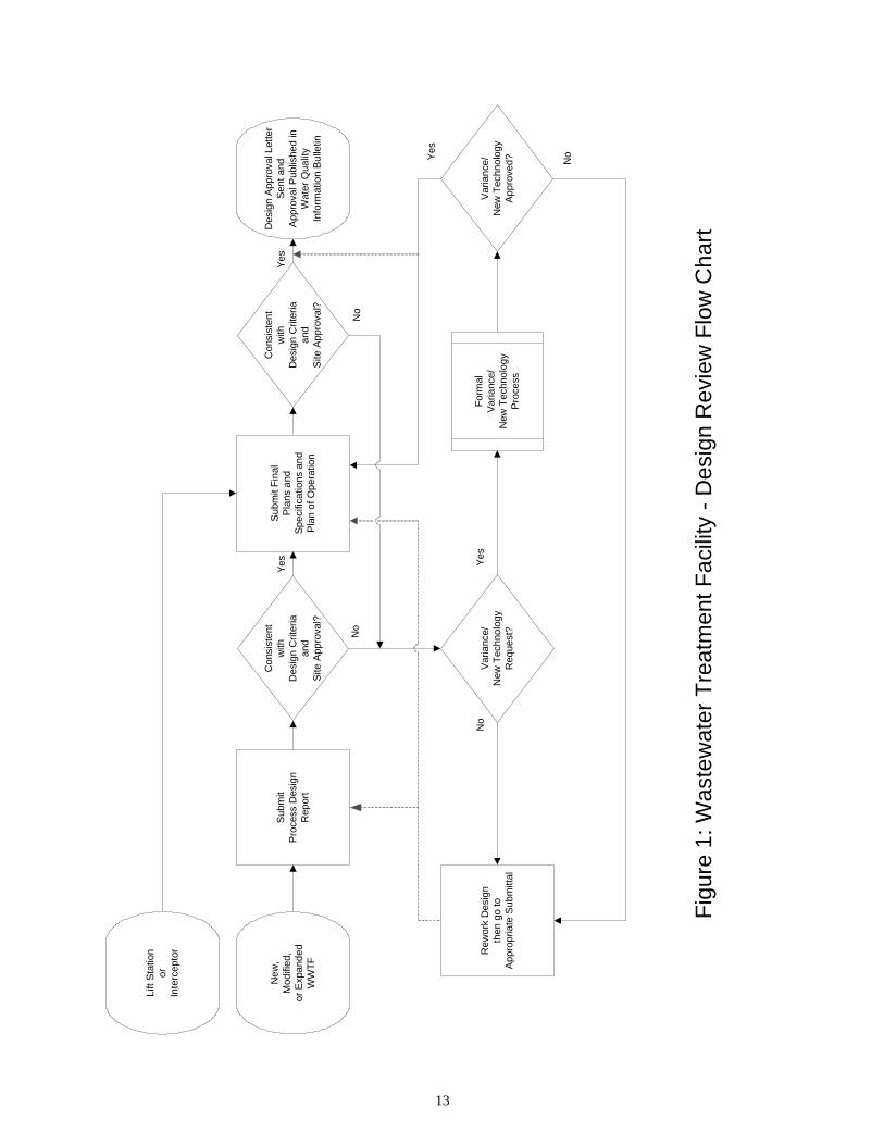
Title Page Figure 1. Wastewater Treatment Facility Design Review Flow Chart........................................13
ii
CHAPTER 1
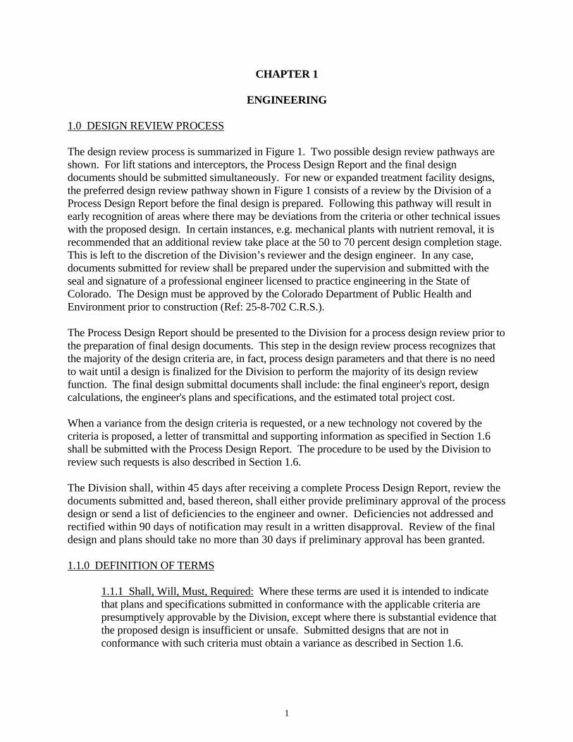
ENGINEERING 1.0 DESIGN REVIEW PROCESS The design review process is summarized in Figure 1. Two possible design review pathways are shown. For lift stations and interceptors, the Process Design Report and the final design documents should be submitted simultaneously. For new or expanded treatment facility designs, the preferred design review pathway shown in Figure 1 consists of a review by the Division of a Process Design Report before the final design is prepared. Following this pathway will result in early recognition of areas where there may be deviations from the criteria or other technical issues with the proposed design. In certain instances, e.g. mechanical plants with nutrient removal, it is recommended that an additional review take place at the 50 to 70 percent design completion stage. This is left to the discretion of the Division’s reviewer and the design engineer. In any case, documents submitted for review shall be prepared under the supervision and submitted with the seal and signature of a professional engineer licensed to practice engineering in the State of Colorado. The Design must be approved by the Colorado Department of Public Health and Environment prior to construction (Ref: 25-8-702 C.R.S.). The Process Design Report should be presented to the Division for a process design review prior to the preparation of final design documents. This step in the design review process recognizes that the majority of the design criteria are, in fact, process design parameters and that there is no need to wait until a design is finalized for the Division to perform the majority of its design review function. The final design submittal documents shall include: the final engineer's report, design calculations, the engineer's plans and specifications, and the estimated total project cost. When a variance from the design criteria is requested, or a new technology not covered by the criteria is proposed, a letter of transmittal and supporting information as specified in Section 1.6 shall be submitted with the Process Design Report. The procedure to be used by the Division to review such requests is also described in Section 1.6. The Division shall, within 45 days after receiving a complete Process Design Report, review the documents submitted and, based thereon, shall either provide preliminary approval of the process design or send a list of deficiencies to the engineer and owner. Deficiencies not addressed and rectified within 90 days of notification may result in a written disapproval. Review of the final design and plans should take no more than 30 days if preliminary approval has been granted. 1.1.0 DEFINITION OF TERMS 1.1.1 Shall, Will, Must, Required: Where these terms are used it is intended to indicate
that plans and specifications submitted in conformance with the applicable criteria are presumptively approvable by the Division, except where there is substantial evidence that the proposed design is insufficient or unsafe. Submitted designs that are not in conformance with such criteria must obtain a variance as described in Section 1.6.
1
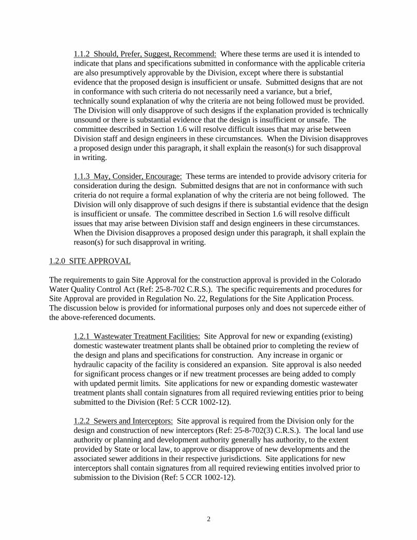
1.1.2 Should, Prefer, Suggest, Recommend: Where these terms are used it is intended to indicate that plans and specifications submitted in conformance with the applicable criteria are also presumptively approvable by the Division, except where there is substantial evidence that the proposed design is insufficient or unsafe. Submitted designs that are not in conformance with such criteria do not necessarily need a variance, but a brief, technically sound explanation of why the criteria are not being followed must be provided. The Division will only disapprove of such designs if the explanation provided is technically unsound or there is substantial evidence that the design is insufficient or unsafe. The committee described in Section 1.6 will resolve difficult issues that may arise between Division staff and design engineers in these circumstances. When the Division disapproves a proposed design under this paragraph, it shall explain the reason(s) for such disapproval in writing.
1.1.3 May, Consider, Encourage: These terms are intended to provide advisory criteria for consideration during the design. Submitted designs that are not in conformance with such criteria do not require a formal explanation of why the criteria are not being followed. The Division will only disapprove of such designs if there is substantial evidence that the design is insufficient or unsafe. The committee described in Section 1.6 will resolve difficult issues that may arise between Division staff and design engineers in these circumstances. When the Division disapproves a proposed design under this paragraph, it shall explain the reason(s) for such disapproval in writing.
1.2.0 SITE APPROVAL The requirements to gain Site Approval for the construction approval is provided in the Colorado Water Quality Control Act (Ref: 25-8-702 C.R.S.). The specific requirements and procedures for Site Approval are provided in Regulation No. 22, Regulations for the Site Application Process. The discussion below is provided for informational purposes only and does not supercede either of the above-referenced documents.
1.2.1 Wastewater Treatment Facilities: Site Approval for new or expanding (existing) domestic wastewater treatment plants shall be obtained prior to completing the review of the design and plans and specifications for construction. Any increase in organic or hydraulic capacity of the facility is considered an expansion. Site approval is also needed for significant process changes or if new treatment processes are being added to comply with updated permit limits. Site applications for new or expanding domestic wastewater treatment plants shall contain signatures from all required reviewing entities prior to being submitted to the Division (Ref: 5 CCR 1002-12).
1.2.2 Sewers and Interceptors: Site approval is required from the Division only for the design and construction of new interceptors (Ref: 25-8-702(3) C.R.S.). The local land use authority or planning and development authority generally has authority, to the extent provided by State or local law, to approve or disapprove of new developments and the associated sewer additions in their respective jurisdictions. Site applications for new interceptors shall contain signatures from all required reviewing entities involved prior to submission to the Division (Ref: 5 CCR 1002-12).
2
1.2.3 Pumping Stations: Site approval for the location of a new, expansion, or rehabilitation of an existing pumping station shall be obtained prior to completing the review of the design plans and specifications for construction (Ref: 5 CCR 1002-12). Rehabilitation that requires a site application is ANY rehabilitation that increases the capacity of the existing facility beyond what has been previously approved. Replacement in-kind is exempted.
1.3.0 PROCESS DESIGN REPORT The purpose of this report is to provide the Division with a complete process design for a new or expanding wastewater treatment facility, thus allowing Division review early in the design process. Separate Process Design Reports should not be submitted for sewer or lift station projects. The Process Design Report shall include the Basis of Design for each unit process utilized for the wastewater treatment plant. The Basis of Design shall demonstrate conformance with the design criteria or provide explanations for deviations as outlined in Section 1.1 above and may possibly be subject to the variance or new technology review procedure described in Section 1.6. The Process Design Report shall include any controlling assumptions instrumental to the functional design of the wastewater treatment facilities as a whole and of each component unit. 1.3.1 General: The Process Design Report shall include at a minimum:
a. Description and purpose of the project, location, climate, topography, geology
and local hydrology. b. Brief description of existing plant (if any). c. Description of contributing service areas. d. Historical (to the extent available or relevance), present, and projected
population figures. e. Flow and loading calculations (present and projected) including any
commercial and industrial contributions and allowing for infiltration/inflow. f. Field survey data including wastewater strength (present and projected), and if
needed, volume and strength of industrial and commercial wastes. g. Colorado Discharge Permit System (CDPS) permit limits or preliminary
effluent limits issued during the Site Approval process. h. Soil investigations and core borings, flood plain location, wetland areas, water
rights impacts, and agricultural lands.
3
1.3.2 Design Calculations: To facilitate the Division’s review of the process design, the engineer should submit design calculations that can be easily used to compare design parameters to the applicable criteria, especially for biological treatment components and clarifiers.
1.3.3 Process Design Report Technical Elements: Enough process design information must be submitted to demonstrate how the design was developed and its conformance with applicable design criteria. A facility layout drawing shall be submitted showing the wastewater treatment plant in relation to the remainder of the collection system. The Process Design Report shall also include:
a. Size and location of plant structures.
b. Schematic flow diagram showing the flow through various unit processes including a preliminary hydraulic profile.
c. General piping arrangements including any by-pass of individual units,
materials handled and direction of flow through pipes.
d. Flow and solids balance showing the flows of raw wastewater, supernatant liquor, all return flows and sludge flows at average and peak design conditions.
e. Pump location, type and size.
f. Type of Treatment: Careful consideration should be given to the type of
treatment before making a final decision. A few of the important factors that should influence the selection: the location and topography of the plant site; the effect of industrial wastes likely to be encountered; operating costs, flexibility, level of treatment required, the probable type of supervision and operation which the plant will have and ultimate costs to the users. New treatment processes, methods and equipment will be reviewed in accordance with the procedure given in Section 1.6.
g. Design Flow Rate: Unless satisfactory justification can be given for using a
lower or higher per capita flow, plans for wastewater treatment plants to serve new sewer systems should be designed on the basis of an average daily per capita (gpcd) wastewater flow of not less than 70 gallons (265 liters) nor greater than 100 gallons (380 liters), to which industrial and commercial wastewater flows must be added. Plans for wastewater treatment plants to serve existing collection systems will be examined on the basis of gauging the present flow in the system plus allowances for infiltration and the estimated future increase in population, commercial and industrial contributions.
h. Industrial waste contributions or other special factors requiring special
treatment processes or other contributions that may impact raw wastewater strength and volume in the design of the facility.
4
i. Calculations showing average, maximum month, and peak flows and organic
loads (and for nutrient loads, when applicable due to permit limits) for present and design conditions, for each treatment unit.
j. Process design parameters for each treatment unit process referencing the
applicable design criteria.
k. Oxygen transfer calculations and data used for oxygen transfer equations. Include blower or aerator sizing and air flow requirements for treatment and mixing.
1.3.4 Preliminary Operating Plan: A preliminary plan of operation shall be included in the Process Design Report. The plan of operation shall describe in general terms the number of operators, their certification level, their expected number of work shifts per week, the expected basic operating configuration and process control procedures, residuals management plan, phased operation to maintain permit compliance (if applicable during construction), and emergency response concept.
1.4.0 FINAL DESIGN SUBMITTAL – PLANS AND SPECIFICATIONS A professional engineer registered in the State of Colorado must stamp and sign all plans.
1.4.1 Sewer Project Plans: The Division will review design and plans for new collection systems, extensions and replacement sewers only when designed in conjunction with a project involved in a State loan or grant process or if the project involves a new interceptor (sewer greater than or equal to 24 inches in diameter). The engineering report shall include a description of existing and proposed sewers, including the extent of existing sewers involved, the sizes and capacities of new and proposed sewers and the distance between manholes. The following data for tributary areas for existing and proposed conditions at critical points in the system shall be included in the report:
a. Design Period: Local collection systems should be designed for the estimated ultimate tributary flow (based on population). Interceptors may be designed for ultimate build-out, but may also be staged in 10 to 20 year increments (20 years being preferred).
b. Population Densities per Acre and Total Population: Data should be included
with regard to surrounding and/or downstream areas if the sewers are to be tied into an existing system.
c. Areas served in acres or square miles.
d. Average and Maximum Per Capita Sewage Contribution: Unless satisfactory
justification can be given for using a lower or higher per capita flow, new sewer systems should be designed on the basis of an average daily per capita (gpcd)
5
flow of wastewater of not less than 70 gallons (265 liters) nor greater than 100 gallons (380 liters). This figure is assumed to cover normal infiltration, but an additional allowance should be made where conditions are unfavorable. Generally, peak flow to average flow ratios for sewers should, when running fully, not be less than 4:1 for laterals and sub-main sewers and not less than 2.5:1 for main, trunk, and outfall sewers. These ratios may be adjusted where there is site-specific data to document the use of other figures.
e. Infiltration/Inflow.
f. Industrial and commercial wastewater contributions, including regional service
commercial areas, i.e. auto dealer plazas and shopping malls.
g. Overall design average and maximum flow rates.
h. Size of pipe, grade, velocity, and maximum capacity.
i. Feasibility of flow leveling.
Detailed Plans: Plans shall be submitted with profiles having a horizontal scale of not more than 100 feet to the inch (1:100 engineers scale) with a corresponding vertical scale. Plans and profiles shall show:
a. Location of streets and sewers. b. Line of ground surface, size, material and type of pipe, length between
manholes, invert and surface elevation at each manhole and grade of sewer between each two adjacent manholes.
c. Locations of all special features such as inverted siphons, concrete encasements,
highway crossings, elevated sewers, etc. d. Locations of all known existing structures, both above and below ground, which
might interfere with the proposed construction, particularly water mains, gas mains, storm drains, telephone lines, etc.
e. Special detail drawings, made to a scale to clearly show the nature of the
design, shall be furnished and show at least the following:
1. All stream crossings and sewer outlets, with stream-bed elevations and normal and extreme high and low water levels.
2. Details of all special joints and cross-sections.
6
3. Details of all sewer appurtenances such as manholes, lamp holes, inspection chambers, inverted siphons, regulators, relief valves, tide gates, thrust blocks, elevated sewers, etc.
f. System head calculations shall include the size and length of force mains and
assumed c (friction) factor.
1.4.2 Wastewater Pumping Station Plans: For wastewater pumping stations, the engineering report shall include information regarding the contributory areas, basis of design, pertinent information in 1.4.1 (above) and other essential features. A plan shall be submitted for the project involving new construction or revision of wastewater pumping stations showing the location and extent of the tributary area, any municipal boundaries within the tributary area, the location of the pumping station and force main and pertinent elevations. Design considerations should include station size, type of construction, pump and motor selection, system design, controls, valves, piping, access and pumping efficiency.
A basis of design for all wastewater pumping stations shall be prepared and submitted to assist the Division in reviewing the project plans and specifications. The basis of design shall include, but not necessarily be limited to, the following:
a. Average and peak flow calculations for present and design conditions. b. Wet well configuration and size. c. Number, type, capacity, motor horsepower and Net Positive Suction Head
(NPSH) requirements of proposed pumping units. Motors shall be protected from over-current, over-temperature and voltage imbalance.
d. System head curve and head computations for design conditions of pumping
system. (Future pumping capacity requirements should be considered in sizing pumping equipment).
e. System head calculations shall include the size and length of force main static
head and all dynamic losses. f. Calculations showing flotation potential and proper ballasting. g. Description of primary and back-up power sources.
Detailed Plans: Plans shall be submitted showing the following, where applicable:
a. A contour map of the property to be used. b. Proposed pumping station, including provisions for installation of future pumps
or ejectors.
7
c. Existing pumping station, if applicable. d. Elevation of high water at the site (100 year flood elevation). e. Maximum elevation of wastewater in the collection system and wet well in the
event of a power failure for the estimated duration of power outage. f. Detailed electrical and control system plans. g. Detailed plans for the force main as per 1.4.1 above. h. Detailed plans for the pumping station building and all appurtenances. i. Test borings and groundwater elevations. j. A plan of operation and sequence of events for continuous and safe transfer of
wastewater during the construction.
1.4.3 Wastewater Treatment Plant Plans: Process design and Process Design Report requirements were discussed in Section 1.3. Again, the preference is that a Process Design Report will be submitted and that the process design will be approved prior to submitting final design documents. Any changes to the process design or other items included in the Process Design Report must be noted in the final design submittal.
Detailed Plans: Plans of wastewater treatment plants shall show the following:
a. Location, dimensions, elevations, and details of all affected existing and proposed plant facilities.
b. Architectural, mechanical, electrical, structural and civil details of all affected
existing and proposed plant facilities and appurtenances.
c. Elevations of high and low water level of the body of water to which the final effluent is to be discharged, including the 100-year flood elevation.
d. Adequate description of any features not otherwise covered by specifications.
e. Special detail drawings made to a scale to clearly show the nature of the design.
f. Test borings and groundwater elevations.
g. Roads and access points for the treatment facility.
h. Number, type, capacity, motor horsepower (kilowatts) and NPSH requirements
of proposed pumping units.
8
i. Future pumping capacity requirements should also be considered in sizing
pumping equipment.
1.4.4 Specifications: Complete technical specifications for the construction of interceptor sewers, wastewater pumping stations, wastewater treatment plants, and all appurtenances shall accompany the final plans. A system head curve or head computations for design conditions of the pumping system should be included. Specifications must contain a program for maintaining existing treatment plant units in operation to the extent needed during construction of plant additions to ensure that all discharge permit requirements are met during construction.
1.5.0 REVISIONS TO PLANS Any deviations from approved plans or specifications affecting capacity, flow, or operation of units shall be submitted in writing before such changes are made. Changes affecting capacity will require a new Site Approval. This does not apply to construction change orders that do not impact capacity, flow or unit operations.
"As Recorded" drawings clearly showing any major alterations shall be prepared and furnished to the owner and the Division at the completion of the work. The submittals to the Division may be as a reduced set of drawings or a certification from the engineer stating the revisions and changes to the Division-approved set of plans and specifications.
1.6.0 SUBMITTAL AND DESIGN REVIEW PROCEDURE FOR VARIANCES AND NEW TECHNOLOGIES When a design document is submitted for review (either Process Design Report or final plans and specifications documents) the design parameters will be compared with these design criteria in accordance with the definitions provided in Section 1.1. When a proposed design includes new technologies not covered by the criteria (or not previously used in the State) or does not conform to “shall, will, must, required” criteria, then, upon request by the owner, design engineer, or Division staff, the Division’s New Technology and Design Criteria Variance Committee (Committee) shall review the design. The Committee will also resolve technical issues as described in Section 1.1. The Committee will provide a thorough and consistent technical review of such circumstances on a case-by-case basis. It is recognized that, at times, it may not be clear if a substantial reconfiguration of existing treatment technologies constitutes a “new technology”; the Committee will make such determinations. The Committee shall also keep a record of previously approved new technologies and commonly granted variances so that these efforts will not need to be repeated unnecessarily. There are both administrative and technical items that must be presented to support such requests as follows (unless there is a documented reason as to why the information does not exist).
1.6.1 New Technology Design Review Requests: The request to review a new treatment technology not covered by the design criteria (or not previously used in the State) shall include the following administrative and technical documentation:
9
a. Administrative Documentation:
1. Statement of recognition signed by the facility owner and the design engineer that a new technology is being proposed. The statement must recognize the fact that the owner is responsible for repaying the full amount of any loans provided for the new treatment technology and paying for additional treatment works if the new technology does not meet permit limits.
2. Discussion of any applicable manufacturer’s warranty and/or
performance warranty. 3. Estimate of increased operator attention needed during startup and the
first year of operation. 4. Discussion of additional sampling and monitoring that will be
performed to verify the performance of the new technology. 5. Documentation of how operators will be trained to properly operate,
control and maintain the facility. 6. Full disclosure of any relationships between the engineer and
manufacturer or vendor.
b. Technical Documentation:
1. Theory and calculations demonstrating how the new technology functions, unless such information is specifically documented as proprietary, e.g. the basis of a patent.
2. Actual operating experience and/or pilot test work. 3. Comparison of flow and flow variations of other installations of the
technology with the proposed application (within +/- 25% preferable). 4. Comparison of organic, and if applicable, nutrient loading and loading
variations of other installations of the technology with the proposed application (within +/- 25% preferable).
5. Comparison of operating conditions (including temperature, altitude,
etc.) of other installations of the technology with the proposed application (similar conditions preferable).
6. Compliance history (e.g. effluent quality compared to permit limits) of
other installations of the technology.
10
7. Comparison of discharge quality and limits of other installations of the
technology with the proposed application 8. Full cost comparison of the proposed new technology with existing
technologies designed in conformance with design criteria including capital costs and annual operating and maintenance costs, considering operator certification and additional monitoring requirements.
Approvals are much more likely to be given to requests that include all the administrative and technical information items specified above. Preference will be given to new technologies that have been thoroughly tested and installed with successful operating and compliance track records with operating conditions, effluent permit limits and sample collection requirements similar to the proposed application.
If full-scale operating experience is not available, then pilot test data will be considered. However, preference will be given to tests conducted by a competent sanitary or environmental engineer other than one employed by the manufacturer or developer of the process. Samples from the pilot test should be collected and analyzed to show treatment efficiency under various ranges of raw wastewater strength and volume and over a sufficient length of time to demonstrate operation under climatic and operating conditions that may be encountered in the proposed application. Where such test data are not available, commonly used sound engineering design assumptions shall be submitted as reference.
1.6.2 Design Criteria Variance Requests: The request to review a variance from the design criteria shall include the following administrative and technical documentation:
a. Administrative Documentation:
1. Statement of recognition signed by the facility owner and the design engineer that a variance is being requested. The statement must recognize the fact that the owner is responsible for repaying the full amount of any State loans provided for the new treatment technology and paying for additional treatment works if the new technology does not meet permit limits.
2. Discussion of applicable manufacturer’s warranty and/or performance
warranty. 3. Full disclosure of any relationships between the engineer and
manufacturer or vendor.
Depending on the nature of the requested variance, the Committee may request information similar to items 1.6.1.a.4 to 1.6.1.a.6 above.
11
b. Technical Documentation:
1. Theory and calculations demonstrating how the treatment plant will function if the variance is granted, unless such information is specifically documented as proprietary, e.g. the basis of a patent.
2. Actual operating experience and/or pilot test work. 3. Full cost comparison of the proposed new technology with existing
technologies designed in conformance with design criteria including capital costs and annual operating and maintenance costs, considering operator certification and additional monitoring requirements.
Again, depending on the nature of the requested variance, the Committee may request information similar to items 1.6.1.b.4 to 1.6.1.b.8 above.
Approvals are much more likely to be given to requests to requests that include all the administrative and technical information items specified above and requested by the Committee. Preference will be given to proven technologies and techniques that have been thoroughly tested and installed with successful operating and compliance track records with operating conditions, effluent permit limits and sample collection requirements similar to the proposed application.
12
Sub
mit
Pro
cess
Des
ign
Rep
ort
Con
sist
ent
with
Des
ign
Crit
eria
and
Site
App
rova
l?
Sub
mit
Fina
lPl
ans
and
Spec
ifica
tions
and
Pla
n of
Ope
ratio
n
Var
ianc
e/N
ew T
echn
olog
yR
eque
st?
Rew
ork
Des
ign
then
go
toA
ppro
pria
te S
ubm
ittal
Form
alV
aria
nce/
New
Tec
hnol
ogy
Pro
cess
Var
ianc
e/N
ew T
echn
olog
yA
ppro
ved?
Figu
re 1
: Was
tew
ater
Tre
atm
ent F
acili
ty -
Des
ign
Rev
iew
Flo
w C
hart
Con
sist
ent
with
Des
ign
Crit
eria
and
Site
App
rova
l?
Yes
Yes
No
No
No
Yes
Yes
No
New
,M
odifi
ed,
or E
xpan
ded
WW
TF
Lift
Stat
ion
orIn
terc
epto
r
Des
ign
App
rova
l Let
ter
Sen
t and
App
rova
l Pub
lishe
d in
Wat
er Q
ualit
yIn
form
atio
n B
ulle
tin
13
CHAPTER 2
WASTEWATER CONVEYANCE SYSTEMS
2.1.0 GENERAL The Division will review designs and plans for new collection systems, extensions and replacement sewers only when designed in conjunction with a project involved in a State loan or grant process or if the project involves a new interceptor (sewer greater than or equal to 24 inches in diameter). Designs of collection systems and interceptors will be accepted only if they exclude rainwater from roofs, streets, and other areas, and groundwater from foundation drains and other areas. Entities are encouraged to use these criteria as a general guidance and minimum standard for construction of new sewer lines in their service areas whether or not the Division will review the design. 2.2.0 SEWER DESIGN
2.2.1 Minimum Size: Public sewers, except under special conditions, should not be less than 8 inches (20 centimeters) in diameter.
Special Conditions: Under special conditions, such as low tributary population, small diameter sewer technology may be used. Small diameter technology may include pressure, vacuum and small diameter gravity sewers. However, service laterals should not be less than 2 inches (5 centimeters) in diameter and sub-mains should not be less than 4 inches (10 centimeters) in diameter.
2.2.2 Depth: In general, sewers should be designed deep enough to drain basements and lower level bathroom facilities by gravity and to prevent freezing.
2.2.3 Slope: To prevent solids deposition, all sewers should be so designed and constructed as to transport average sewage flows at mean velocities of 2.0 feet per second (0.6 meters per second), based on a reasonable formulation and roughness factor. The slope between manholes should be uniform for conventional sewers. Where the above design would not be practical due to low tributary population, as would often be the case with laterals and sub-mains, 8-inch (20 centimeters) sewers should be installed at a slope of at least 0.4%.
Low tributary population: Where low tributary population utilizes small diameter sewer technology, a variable grade sewer is allowable. Proper location of cleanouts, pressure relief valves and manholes are required. A scheduled maintenance program to prevent clogging is required.
2.2.4 Alignment: Sewers should be laid with straight alignment between manholes. Alignment tests such as "lamping" should be conducted on conventional systems. In subdivisions where street layouts are such that straight alignment between manholes is
14
impractical, sewers may be curved to conform with street curvature. The radius of a curvature should not be less than 100 feet (30 meters). It is suggested that the sewer curvature be made concentric with the street curvature to simplify layout work and locating the lines at a later date. An alignment test such as "balling" should be conducted on curved sewers. The entity responsible for maintenance should recognize that additional maintenance may be necessary.
Special conditions: Sewers designed with small diameter technology may be curved to conform with the topography or street curvature. The radius of the curvature should not be less than that allowed by the pipe manufacturer or by the equation:
Rb = (OD) * 200. Where: Rb = Minimum curvature radius OD = Outside diameter of the pipe.
2.2.5 Increasing Size: When one sewer joins a larger one, the invert of the larger sewer should be lowered sufficiently to maintain the same energy gradient.
2.2.6 High Velocity Protection: Where velocities greater than 15 feet per second (4.6 meters per second) are attained, special provisions should be made to protect against deterioration or displacement by erosion and shock.
2.2.7 Materials: Any generally accepted material for sewers can be considered, but the material selected should be adapted to local conditions, such as character of industrial wastes, possibility of septic conditions, temperature, soil characteristics, exceptionally heavy external loadings, abrasion, corrosion and similar problems. All sewers should be designed to prevent damage from superimposed loads. Bedding and backfill material should be included in the specifications.
2.2.8 Joints and Infiltration: The method of making joints and the materials used must be included in the specifications. Sewer joints should be designed to minimize infiltration and to prevent the entrance of roots. Leakage tests should be specified. This may include water or low pressure air testing. The testing methods should take into consideration the range in groundwater elevations during the test and the sewer’s anticipated design life. For water (hydrostatic) tests, the exfiltration or infiltration should not exceed 200 gallons per day per inch of pipe diameter per mile (185 liters/day/centimeter diameter/kilometer) for any section of the system with a minimum positive head of 2 feet.
2.2.9 Deflection Test: Deflection testing of a portion of, or all, flexible pipe installations to assure the quality of construction should be considered. Flexible pipe is considered to be a conduit that will deflect at least 2 percent without any sign of structural distress. Deflection tests, when performed on PVC pipe, should be conducted in accordance with ASTM D3034 and satisfy either of the following limitations:
15
a. For 7 days minimum period between trench backfilling and testing – 95.0 minimum mandrel diameter as a percent of the inside pipe diameter.
b. For 30 days minimum period between trench backfilling and testing – 92.5
minimum mandrel diameter as a percent of the inside pipe diameter.
2.2.10 Buoyancy: Buoyancy of sewers must be considered and pipe flotation must be prevented with appropriate construction where high groundwater conditions are anticipated.
2.2.11 Miscellaneous: Thrust block location, reinforced or special connections, pressure relief valves, and other appurtenances should be considered in gravity and force main conveyance systems.
2.3.0 MANHOLE DESIGN
2.3.1 Location: Manholes should be installed at the end of each line; at all changes in grade, size, or alignment; and at all pipe intersections. For entities without a sewer cleaning program and equipment, installations at distances not greater than 400 feet (120 meters) for sewers 15 inches (38 centimeters) in diameter or less, and 500 feet (150 meters) for sewers 18 inches to 30 inches (46 t 76 centimeters) in diameter should be considered. For larger sewers, greater spacing is a possibility. Cleanouts should not be substituted for manholes.
Special conditions: Sewers designed with small diameter technology, cleanouts may be used in certain instances instead of manholes. Manholes should still be used for proper maintenance and inspection of the system.
2.3.2 Drop Type: An outside drop pipe should be provided for a sewer entering a manhole at an elevation of 24 inches (0.6 meters) or more above the manhole invert. Where the difference in elevation between the incoming sewer and the manhole invert is less than 24 inches (0.6 meters), the invert should be filleted to prevent solids deposition.
Drop manholes can enhance the release of hydrogen sulfide gas that can lead to corrosion and noxious odors in the interceptor and collection system and should be constructed with an outside drop connection. Inside drop constructions (when necessary) must be secured to the interior wall of the manhole and provide access for cleaning.
Encasing the entire outside drop connection in concrete is recommended due to the unequal earth pressure that would result from backfilling near the manhole.
2.3.3 Diameter: The minimum inside diameter of manholes should be 48 inches (1.2 meters).
16
2.3.4 Flow Channel: The flow channel through manholes should be made to conform in shape and slope to that of the sewers. The sewer pipe should lay through the manhole when alignment allows.
2.3.5 Bench: A sloped bench should be provided on each side of any manhole channel when pipe diameter(s) are less than the manhole diameter. The bench should be sloped no less than the manhole diameter. A lateral sewer, service connection, or drop manhole must not discharge onto the bench surface.
2.3.6 Watertightness: Solid manhole covers are to be used wherever the manhole tops may be flooded by street runoff or high water. Locked manhole covers should be considered in isolated easement locations or where vandalism may be a problem.
2.3.7 Inspection and Testing: The design specifications must include a requirement for inspection and testing water-tightness or damage prior to placing into service.
2.3.8 Corrosion Protection for Manholes: Where corrosive conditions due to septicity or other causes are anticipated, providing corrosion protection on the manhole interior is recommended.
2.4.0 INVERTED SIPHON DESIGN Inverted siphons should have not less than two barrels, with a minimum pipe size of 6 inches (15 centimeters), and should be provided with necessary appurtenances for convenient flushing and maintenance; the manholes should have adequate clearance for rodding; and in general, sufficient head should be provided and pipe sizes selected to secure velocities of at least 3.0 feet per second (1.0 meters per second) for average flows. The inlet and outlet details should be arranged so that the normal flow is diverted to one barrel and so that either barrel may be taken out of service for cleaning. 2.5.0 PROTECTION OF WATER SUPPLIES
2.5.1 Water Supply Inter-connections: There shall be no physical connection between a public or private potable water supply system and a sewer, or appurtenance thereto which would permit the passage of any sewage or polluted water into the potable supply.
2.5.2 Relation to Water Works Structures: While no general statement can be made to cover all conditions, it is generally recognized that sewers must be kept remote from public water supply wells or other water supply sources and structures. Refer to the State Engineers office for specific regulations on set backs and safe distances for protection of potable water supplies.
2.5.3 Relation to Water Mains: Where sewer lines cross water mains or come within 10 horizontal feet (3.0 meters) of each other, the sewer pipe shall be a minimum of 18 inches (46 centimeters) clear distance vertically below the water main. If this clear distance is not feasible, the pipe section must be designed and constructed so as to protect the water main.
17
Minimum protection shall consist of the installation of an impervious and structural sewer. For example: at crossings,
a. One length of pipe at least 18 feet (6.0 meters) long centered over the water main. Joints between the sewer pipe and the special length pipe shall be encased in a concrete collar at least 6 inches (14 centimeters) thick and extending at least 6 inches (14 centimeters) either side of the joint.
b. Non-structural pipe shall be reinforced with a reinforced concrete encasement.
The encasement shall be at least 6 inches (14 centimeters) thick and extend a distance of 10 feet (3.0 meters) either side of the water main.
In all cases, proper soil compaction, suitable backfill or other structural protection shall be provided to preclude settling and/or failure of either pipe.
2.6.0 SPECIAL DESIGN PROBLEMS
2.6.1 Underwater Gravity Systems: Where possible, underwater systems should be avoided. If the designer can show that an underwater system is cost-effective and can be adequately maintained, the Division, on a case-by-case basis can consider such a system. Materials will be suitable to withstand forces similar to a pressure pipe system.
Pipe will be cast or ductile iron, pre-stressed concrete or other suitable material able to withstand underwater forces and resist buoyancy. Interior coatings for corrosion and erosion protection shall be provided to insure prolonged life. Screening chambers shall be provided at all points to underwater systems.
Design of these structures and devices shall provide a positive bar to the entry of material that would contribute to any obstructions of the underwater parts of the system. Valves at points of entry and exit of the underwater system so that pressure flushing can be accomplished and so that the line can be isolated in the event of an underwater failure shall be provided. Cleanout or flushing wye's should be placed approximately every 1,000 feet (300 meters), or at significant deflections, with access from dry land, and shall be designed to avoid damage from ice or frost. 2.6.2 Stream Crossing:
a. Cover Depth: The top of all sewers crossing streams shall be at a sufficient depth below the natural streambed bottom to protect the sewer line. Proposed cover, pipe and backfill requirements will be reviewed on a case-by-case basis and approved only if the proposed sewer crossing will not interfere with future improvements to the stream channel.
b. Horizontal Location: Sewers located along streams shall be located outside of
the streambed and be sufficiently removed from the streambed to allow at least
18
minimal future possible stream widening and to prevent pollution by siltation during construction.
c. Structures: The sewer outfalls, headwalls, manholes, gate boxes, or other
structures shall be located so do not interfere with the free discharge of stream flood flows.
d. Alignment: Sewers crossing streams should be designed to cross the stream as
nearly perpendicular to the stream flow as possible and gravity sewer crossings shall be designed to minimize the number of stream crossings.
e. Construction: Stream crossings may be open-cut excavation, inverted siphon,
bridge crossings or gravity boring under the streambed. Sewers crossing streams shall be constructed such that they are capable of absorbing pipe movement and joint-deflection while remaining intact and watertight and free from changes in alignment or grade. Trench backfill material shall not readily erode, cause siltation, damage pipe during placement or cause chemical erosion to the pipe.
Construction methods that minimize siltation and erosion shall be employed. The design engineer shall include the construction methods to be employed for sewers in or near streams in the design plans and specifications. Obtaining an Army Corps of Engineers Section 404 permit is a separate activity and conformance with the Design Criteria does relieve an entity of those requirements. Sewer lines shall be protected from scour and 100-year flood velocities. Specifications must include cleanup, grading, seeding planting or restoring all work areas as soon as practicable.
2.6.3 Bridge Crossing: The Colorado Department of Transportation, specific Railroad Company, County or City transportation divisions or other entities responsible for bridge design, should be contacted for proper design, construction and any permits required for any sewer transmission line utilizing existing bridges for road and stream crossings. Stream crossings utilizing the pipe as a bridge should have proper head wall designs, pipe elevation above the stream and guy anchors for protection from the 100 year flood.
19
CHAPTER 3
WASTEWATER PUMPING STATIONS (Lift Stations)
3.1.0 GENERAL The Division will require a basis of design to be submitted with the detailed plans and specifications for all wastewater pumping stations. Discharging raw sewage to State waters is unacceptable under any circumstances. Wastewater pumping stations shall not be subject to damage by a 100-year flood event. A suitable superstructure, preferably located off the right of way of streets and alleys should be provided.
3.1.1 Accessibility and Security: The station must be readily accessible. The pumping station should be readily accessible to maintenance vehicles under all weather conditions. The facility should be located off the traffic way of streets and alleys. Security fencing and access hatches with locks should be provided.
3.2.0 DESIGN 3.2.1 General:
a. Type: Sewage pumping stations of the wet well/dry well and submersible types may be considered.
b. Structures:
1. Separation: Wet and dry wells, including their superstructure, should be completely separated. Common walls must be gas tight.
2. Equipment Removal: P rovision shall be made to facilitate removing
pumps, motors, and valves. 3. Access: Suitable and safe means of access shall be provided to dry
wells of pump stations and wet wells containing either bar screens or other mechanical equipment requiring inspection or maintenance. Ventilation is required in both types of wells. Stairways are preferred over ladders for access.
4. Housing: Housing for pumping equipment and controls shall be readily
accessible and weather proof. 5. Cleaning (Grit): Where wastewater must be pumped prior to grit
removal, the wet well and the discharge piping shall be designed to prevent grit accumulation.
20
6. Buoyancy: Where high groundwater conditions are anticipated, buoyancy of the wastewater pumping station should be considered and adequate protections provided if necessary.
7. Overflow Protection: Provision must be made for emergency storage of
raw sewage or portable pumping in the event of an extended power outage or electrical or mechanical failure. Discharge structures are prohibited. See Section 3.2.2.h for power supply requirements. An emergency storage structure and an alternate power source could be required for a wastewater pumping station. To make this determination consideration will be given to the proximity of the pumping station to surface waters and the designated use of such surface waters including immediate downstream users and the alarm systems installed, emergency response procedures, and response time of the entity to an emergency.
3.2.2 Equipment:
a. Pumps:
1. Duplicate units: At least two pumps must be provided. If only two units are provided, they should have the same capacity. Each pump shall be capable of handling flows in excess of the expected maximum flow. Where three or more pumps are provided, they should be designed to fit actual flow conditions and must be of such capacity that with any one pump out of service, the remaining pumps will have capacity to handle the design peak hourly wastewater flows. For ejector-type lift stations, at least two pneumatic ejectors and compressors are required. Also, the pump sizing should allow for a flow velocity of at least 2 feet per second in the force main.
2. Protection Against Clogging: Readily accessible screens with clear
openings selected to protect the pumps should precede pumps handling raw wastewater, unless pneumatic ejectors are used or special devices such as comminutors are installed to protect the pumps from clogging or damage. Where screens are located below ground, convenient facilities must be provided for handling screenings. For the larger or deeper stations, duplicate units of proper capacity are preferred. Under special conditions, such as low tributary population where small diameter sewer technology is being used, grinder pumps may be utilized for pumping septic tanks to the collection system.
3. Pump Openings: Pumps should be capable of passing spheres of at least
3 inches (8 centimeters) in diameter unless other equipment is provided to prohibit such solids from entering the suction side of the pump. Pump
21
suction and discharge openings shall be at least 4 inches (10 centimeters) in diameter for conventional non-clogging pumps.
4. Priming: The pump should be so placed that under normal operating
conditions, it will operate under a positive suction head. The NPSH and suction lift requirements of the pumps shall be considered.
5. Electrical Equipment: Electrical equipment in enclosed places where
gas may accumulate, shall comply with the latest National Fire Protection Association (NFPA) Codes or the latest National Board of Fire Underwriters' specifications for hazardous locations or submersible locations. Electrical equipment for pump motors should contain elapsed time meters.
6. Intake: Each pump should have an individual intake. Wet well design
should be such as to avoid turbulence near the intake and cavitation in the pump.
7. Dry Well Dewatering: A separate sump pump shall be provided in dry
wells to remove leakage or drainage with the discharge to the wet well above the overflow level of the wet well. Water ejectors connected to a potable water supply will not be approved. All floor and walkway surfaces should have an adequate slope to the drainage point.
8. Pumping Rates: The pumps and controls of main pumping stations, and
especially pumping stations operated as part of a treatment works, should be selected to operate at varying delivery rates to permit discharging wastewater from the station to the treatment works at approximately the rate of delivery to the pump station. The hydraulic constraints of downstream treatment works must be considered for peak pumping rates to prevent overloading.
b. Controls: Liquid level controller activators should be located so that they will
not be affected by flows entering the wet well or by the suction of the pumps. Float tubes in dry wells shall extend high enough to prevent overflow. In small stations with duplicate units, provisions should be made to provide automatic alternations of the pumps in use.
c. Valves: Suitable shutoff valves shall be placed on suction and discharge lines
of each pump. A check valve or pump control valve shall be placed on each discharge line, between the shutoff valve and the pump. Suction shutoff valves may not be needed on vacuum primed pumps, self-primed pumps or submersible pumps.
22
d. Wet Wells:
1. Divided Wells: Where continuous pump station operation is required, consideration should be given to dividing the wet well into two sections, properly interconnected, to facilitate repairs and cleaning.
2. Size: The effective capacity of the wet well should provide a holding
period not to exceed 30 minutes for the design minimum flow. Smaller wet wells may be considered when utilizing variable capacity pumping systems. For large peak flow ratios, extended pumping ranges or extended holding times will be considered.
3. Floor Slope: The wet well floor should have a minimum slope of 1 to 1
to the hopper bottom. The horizontal area of the hopper bottom should be no greater than necessary for proper installation and function of the pump inlet.
e. Ventilation: Adequate ventilation shall be provided for all pump stations to
mechanically ventilate the dry well. If screens or mechanical equipment requiring maintenance or inspection are located in the wet well, it shall be mechanically ventilated. There shall be no interconnection between the wet well and dry well ventilating systems. In pits over 15 feet (4.5 meters) deep, multiple inlets and outlets are desirable. Dampers should not be used on exhaust or fresh air ducts, and fine screens or other obstructions in the air ducts should be avoided to prevent clogging. Switches for operation of ventilation equipment should be marked and located conveniently. Consideration should be given to automatic controls where intermittent operation is practiced. In climates where excessive moisture or low temperatures are a problem, consideration should be given to installing heating and/or dehumidification equipment.
1. Wet Wells: Where mechanical wet well ventilation is required, it
should be continuous and should provide at least 12 complete air changes per hour. For intermittent operation, at least 30 complete air changes per hour should be provided.
2. Dry Wells: Ventilation may be either continuous or intermittent. For
continuous operation, at least 6 complete air changes per hour should be provided. For intermittent operation, at least 30 complete air changes per hour should be provided.
f. Flow Measurement: All pumping stations should have suitable devices for
measuring, recording and totaling sewage flow and power consumption. However, hourly use recording shall be considered for a maintenance program.
23
g. Water Supply: There shall be no physical connection between any potable water supply and a sewage pumping station, which under any conditions might cause contamination of the potable water supply. If a potable water supply is brought to the station, it shall comply with conditions stipulated under paragraph 4.4.2.
h. Power Supply: Power supply must be available from at least two independent
generating sources (two different sub-stations), or emergency power equipment shall be provided. The need for automatic starting vs. manual starting of emergency power equipment shall be evaluated for each project.
i. Alarm Systems: Alarm systems shall be provided for pumping stations. The
alarm shall be activated in case of power failure, pump failure, or any cause of pump station malfunction. Where a municipal wastewater facility is monitored 24 hours, pumping station alarms shall be tele-metered to the facility. Where no such monitoring exists, where feasible, alarms should be tele-metered to the local emergency center. Additionally, an audiovisual device (e.g. horn or light) should be installed at the station for external observation unless disallowed by local ordinance.
3.3.0 INSTRUCTIONS, EQUIPMENT OPERATION AND MAINTENANCE Wastewater pumping stations and their operators should be supplied with a complete set of equipment operation and maintenance instructions, including emergency procedures, maintenance procedures, tools and such spare parts as may be considered necessary. All emergency power generation equipment should also be provided with operation and maintenance instructions requiring routine starting and running of such units at full load. 3.4.0 SPECIAL CONDITIONS Pumping station designs that do not follow the above design criteria will be considered according to the Variance Procedure defined in Section 1.6.
24
CHAPTER 4
GENERAL DESIGN CRITERIA FOR WASTEWATER TREATMENT FACILITIES
4.1.0 GENERAL The most current building codes and regulations governing the design and construction of such facilities should be considered during the design phase of all wastewater treatment facilities. These codes should include the most current applicable Building, Electrical, Fire, Mechanical, Plumbing codes and applicable OSHA regulations and local planning and zoning regulations. 4.2.0 DESIGN
4.2.1 Flow Metering/Measuring: The Division will require, as part of the basis of design of any treatment facility, a list of the locations where flow metering and/or measuring devices will be provided. Flow metering requires recording whereas flow measuring does not require recording.
The monitoring of the various flows throughout a wastewater treatment facility as well as the behavior of the plant under various flow and organic loading conditions provides an audit of plant performance. Additionally, flow records provide an aid in forecasting the need for additional treatment capacity. Therefore, the design of any new or expanded wastewater treatment facility shall include adequate flow metering and/or measuring of all pertinent liquid and sludge flow streams.
a. Influent and Effluent Flow Metering: As a general rule, flow metering at the headworks area of any treatment facility should (see 4.2.1.c below) be provided. The metering device shall be equipped with a local flow indication instrument and a flow recording-totalizing device suitable for providing permanent flow records. The recording-totalizing device should be located in the plant control building when practical. Where influent flow metering is not practical and the same results may be obtained from metering at the effluent end of the treatment facility, this type of flow metering arrangement will be considered. Effluent metering will be required in cases where it is required by the CDPS permit. For lagoon systems both influent flow metering and effluent flow measuring capability shall be provided.
b. Metering Accuracy: In locating flow meters, adequate attention shall be
directed to the upstream and downstream hydraulic conditions at each metering device to ensure that flow metering accuracies within + 10% can be maintained as close to the actual flows as possible during the full range of anticipated flow variations.
25
c. In-plant Flow Measuring: Where multiple treatment units are proposed, such as two or more clarifiers or two or more aeration basins, provision shall be included for flow splitting and for measuring capability to control flows to each treatment unit in proportion to the loading requirements. The pacing of chlorine feed and other equipment associated with treatment performance by flow pattern variations is recommended and should be controlled by signals from the flow metering equipment such that the paced unit varies the chemical, etc. in proportion to the flow variations.
d. Flow Measuring Devices: The following types of equipment are commonly
used for flow measurement applications and are acceptable: Parshall Flumes Differential Meter Weirs (various types) Magnetic Meter Propeller Meter Kennison Nozzle Venturi Meter Dall Tube
In some cases the use of elapsed time clocks or plunger pump stroke length and frequency counter will be adequate for measuring pumped flows. Where hour meters are used on pumps, a method must be specified to periodically calculate pump flow capacity. Other flow measuring devices will be considered on an individual basis related to the proposed application.
e. General Flow Measuring Capability: The following locations within a
treatment facility are required/recommended for flow metering/measuring capability:
Metering: Raw sewage influent (Recommended if not required in the CDPS
permit) Re-circulated flows (Recommended) Waste activated sludge flows (Recommended) Return activated sludge flows (Recommended) Recommended measuring: Humus return flows Raw sludge Digester liquid level Digester gas Pumped flows Other significant in-plant wastes
Additionally, it is desirable to measure the in-plant use of air, oxygen, gas (natural or methane), electrical energy and water.
26
4.2.2 Design Loading:
a. Hydraulic Loading: Certain treatment units within a wastewater treatment plant are designed based on the average wastewater flow rate per 24 hours. However, other components should be designed based on peak monthly, weekly or even daily flows.
Where large seasonal variations in loadings occur, the design shall be based on peak season loads. Where the duration of loading is less than 24 hours per day (i.e. schools, subdivisions, recreational facilities, etc.) treatment units and equipment shall be increased in size by the factor of 24/loading duration (hours) or appropriate equalization facilities shall be provided.
The design engineer must provide the rationale for the selected design flow rate for each unit process in the Process Design Report. Additionally, the flow characteristics from most commercial and industrial developments are usually much more critical than that of a municipality; therefore, the design flow rate for commercial and industrial developments should be based on the period of significant waste discharge. The following considerations should be included in determining design flow:
1. Peak rates of flow, which adversely affect the detention time of treatment units or the flow characteristics of conduits.
2. Data from similar municipalities, in the case of new systems. 3. Wet weather flows. 4. Re-circulation flows.
b. Organic, Solids and Nutrient Loadings: The design organic loading in terms of BOD5, solids loading in terms of total suspended solids and nutrient loadings are usually computed in a manner similar to hydraulic loading and must include re-circulation flows and loads. Designs should be based on maximum month mass loadings (and should account for any variation in monthly, weekly, or daily effluent limits) to ensure that all effluent limits can be met all the time. Loadings for lodges, motels, etc., should be computed for the maximum possible occupancy. The unit of usage, such as number of meals served for a restaurant, is recommended for computation of total organic loading. The shock effect of high contribution for short periods of time should also be considered.
27
4.2.3 Conduits: All piping and channels shall be designed to carry the maximum expected flows. The incoming sewer should be designed for free discharge. Bottom corners of the channels should be filleted. Pockets and corners where solids can accumulate should be eliminated. Suitable gates should be placed in channels to seal off unused sections, which might accumulate solids. The use of shear gates or stop planks is permitted where they can be used in place of gate valves or sluice gates. In larger facilities, fillets may be waived if it can be shown solids accumulation in corners can be minimized without them.
4.2.4 Arrangement and Reliability of Units: Component parts of the plant should be designed and arranged for greatest operating convenience, flexibility, economy, and so as to facilitate routine maintenance and installation of future units. Consideration should be given to providing at least two treatment units of each type to allow maintenance or repairs while maintaining CDPS permit compliance. Plant piping and valving should be designed to allow bypassing of individual units while still providing the maximum practical level of treatment.
4.2.5 Critical Environmental Conditions: The various unit processes and equipment should be designed and sized for the most critical environmental conditions to which they will be exposed at the proposed plant site. Such factors as low and high wastewater temperatures, air temperature, altitude, etc., should be considered, especially when predicting the treatment efficiency to be obtained. The treatment units must be designed to meet any seasonal effluent permit limits
4.3.0 PLANT DETAILS
4.3.1 Installations of Mechanical Equipment: The specifications should be so written that a trained representative of the manufacturer will check the installation and initial operation of major mechanical equipment items.
4.3.2 By-Passes: Properly located and arranged unit by-pass structures shall be provided so that each unit of the plant can be removed from service independently.
4.3.3 Drains: Means should be provided to dewater, empty or pump each unit for maintenance and repair. All drain piping shall be routed back to the headworks of the facility, or to similar units in the facility for proper treatment. Due consideration should be given to the possible need for hydrostatic pressure relief devices.
4.3.4 Construction Materials: Due consideration should be given to the selection of materials which are to be used in wastewater treatment facilities because of the possible presence of hydrogen sulfide and other corrosive gases, greases, oils, and similar constituents frequently present in sewage. This is particularly important in the selection of metals, paints and electrical construction and devices. Contact between dissimilar metals should be avoided to minimize galvanic action.
4.3.5 Painting: The use of paints containing lead should be avoided. In order to facilitate identification of piping, particularly in the large plants (greater than 1.0 mgd), it is
28
suggested that the different lines have contrasting colors. The following color scheme is suggested for purposes of standardization:
Sludge line brown Gas line red Potable water line blue Non-potable water system blue with 6-inch white bands 30 inches apart Chlorine line yellow Sewage line gray Compressed air line green Reclaimed wastewater purple
4.3.6 Operating Equipment: The specifications should include a complete outfit of tools and accessories required for the plant operator's use. A portable pump is desirable. Storage space and a workbench should be provided. Several copies of complete equipment operation and maintenance manuals shall be provided - the number to be determined by the owner.
4.3.7 Grading and Landscaping: Upon completion of the plant, the ground should be graded. Concrete or gravel walkways should be provided for access to all units. Where possible, steep slopes should be avoided to prevent erosion. Surface water shall not be permitted to drain into any unit. Particular care shall be taken to protect trickling filter beds, sludge drying beds and intermittent sand filters from surface wash. Provision should be made for landscaping, particularly when a plant must be located close to residential areas. Consideration should be given to beneficial use of the effluent to irrigate the facility site. The State Engineers office should be contacted for possible water rights issues involved with beneficial use.
4.4.0 ESSENTIAL FACILITIES
4.4.1 Emergency Power Facilities: A standby power source or an emergency basin (subject to infiltration or lining requirements specified in Chapter 5) that influent can be diverted to for up to 12 hours of storage must be provided where a power failure could cause a discharge of partially treated or raw wastewater. The standby source must provide enough power to provide primary treatment and disinfection. The standby source may be either a self-starting generator or a second independent power supply. Generators preferably should be designed to test operate automatically on a regular basis to insure proper function in the event of a power outage. The Division should be consulted regarding each individual case.
4.4.2 Water Supply:
a. General: An adequate supply of potable water under pressure should be provided for sanitary and drinking purposes, use in the laboratory and general cleanliness around the plant. All building plumbing shall comply with the requirements of the applicable plumbing codes. Article 12 of Colorado’s
29
Primary Drinking Water Regulations prohibits uncontrolled cross-connections to a pipe, fixture, or supply, any of which contain water not meeting provisions of the drinking water regulations.
b. Protection of Potable Water Supply from Contamination: State law prohibits
cross-connections that might contaminate a public potable water system. The supply must be physically separated into two systems, a plant potable water system and a plant non-potable water system. The following plumbing installations are considered to comply with the plumbing codes:
1. Plant Potable Water System: Connect the following fixtures directly to
the potable water main on the supply side of the break tank or acceptable backflow preventer. Refer to the applicable plumbing codes concerning types of fixtures, which are acceptable and details regarding proper installation.
i. Lavatory sink (with proper air gap) ii. Hose bib
iii. Showers iv. Emergency showers v. Eye washes
vi. Drinking fountain (angle-jet type) vii. Water closet
All plumbing in this system should be color-coded "blue" in accordance with Section 4.3.5 above.
2. Plant Non-Potable Water System: Where a potable water supply is to
be used for any purpose in a plant other than those listed, a break tank, pressure pump and pressure tank or acceptable backflow preventer shall be provided. Water shall be discharged to the break tank through an air gap at least 6 inches (14 centimeters) above the maximum flood line or the spill line of the tank, whichever is higher. All plumbing in this system should be color-coded "blue with white bands" in accordance with Section 4.3.5 above.
3. Separate Potable Water Supply: Where it is not possible to provide
potable water from a public water supply, a separate well may be provided. Location and construction of the well and the water quality should comply with the requirements of the Colorado Department of Public Health and Environment and the State Engineer’s Office. Since this water supply will be used for sanitary and drinking purposes by the plant operators and visitors, it is considered a public water supply. Therefore, it should be plumbed as outlined in Section 4.4.2 (b) 1.
4. Separate Non-Potable Water Supply: Where a separate non-potable
water supply is to be provided, a break tank will not be necessary but all sill cocks and hose bibs shall be posted with a permanent sign indicating
30
the water is not safe for drinking. The system should be properly color coded in accordance with Section 4.3.5 above.
c. Effect of Water Supply on Piping, Fixtures, and Equipment: Continuous
contact of any of the above water supplied with the associated piping, fixtures, and equipment should not cause these materials to corrode or become deposited at such a rate that impractical maintenance costs will be experienced.
4.4.3 Sanitary Facilities: Suitable hand washing facilities should be provided in all treatment works. Disinfecting soap should be available for use. Where at least 8 hours of operation per day is provided, a shower, water closet, and drinking fountain should also be provided.
4.4.4 Laboratory Space and Equipment: All treatment works shall include a laboratory or other suitable workspace for conducting the on-site analytical tests and operating control tests. The type of testing program required varies with the type and size of the plant.
4.4.5 Floor Slope: Floor surfaces should be sloped adequately to a point of drainage. All drain piping should be routed to the headworks.
4.5.0 BUILDING AND HEAT All mechanical treatment works or mechanical portions of treatment works should be protected from freezing or icing problems from very cold weather. Covers over processes affected by temperature and heating systems shall be considered during the design. Generally, facilities with design flows of less than 0.75 MGD (3.0 x 10³ m3/d) and at elevations above 6000 feet (1.8 kilometers) above Mean Sea Level (MSL) should be enclosed. However, enclosures should be considered for ANY facility in which proper treatment could be affected by extreme cold. Heating should be provided to maintain a minimum of 50o F (10o C) ambient air temperature inside the building(s). 4.6.0 OPERATION AND MAINTENANCE
4.6.1 Preliminary Operating Plan: A preliminary plan for operation shall be included in the process design report. The report must describe in general terms:
a. Number of operators and their certification level. b. The expected number of work shifts per week. c. The expected basic operating configuration and process control procedures. d. Residuals management concept. e. Phased operating procedures to maintain permit compliance (if applicable
during construction).
31
f. Emergency response concept.
4.6.2 Facility Operations and Maintenance Manual: All wastewater treatment facilities shall be furnished with or develop a suitable operations and maintenance manuals. This manual is to describe the overall operation and maintenance of the facility including process operations and controls. It is different from the equipment operating manual discussed above in Section 4.3.6 and should be based on the Operating Plan described above in Section 4.6.1. The owner will determine the number of manuals. The manual(s) will include but not be limited to the following:
a. Discharge permit information. b. Description, operation and control of the wastewater treatment facility and
individual components including handling and disposing of residuals. c. Types and purposes of laboratory tests required for the specific type of
treatment process. d. Types and purposes of record keeping, practices and example record keeping
forms. e. Maintenance schedules and purposes for maintenance for the wastewater
treatment facility and individual components and equipment. f. Safety issues for the wastewater treatment facility and individual components
and equipment.
g. Facility upset and emergency response procedures.
32
CHAPTER 5
SPECIFIC UNIT DESIGN CRITERIA
FOR WASTEWATER TREATMENT FACILITIES
Preliminary treatment refers to removing and handling large solids, grit and debris from the raw wastewater, e.g. bar screens, other screening devices, grit chambers, and shredding. Primary treatment refers to removal of large solids, grit, debris and settleable organic solids prior to secondary treatment. Primary treatment would typically consist of septic tanks or preliminary treatment plus primary clarification or lined settling basin. 5.1.0 PRELIMINARY TREATMENT
5.1.1 Screens or Shredding Devices: Screening devices shall be provided for all mechanical wastewater treatment facilities. The design shall include adequate ventilation. Units shall also be designed to eliminate the potential for plant flooding or bypassing to a watercourse. The purpose of these devices is to remove debris and nuisance material that is generally not capable of biological reduction from entering the downstream treatment processes. If a shredding device is used to grind large debris, a screen or other suitable means of actually removing the debris (including materials that will tend to float in secondary clarifiers) must be installed.
a. Velocity: Design velocity shall be one foot per second at design daily average flow for manually cleaned screens. For mechanically cleaned screens, the maximum velocity shall be 2.5 feet per second (0.75 meters per second). The velocity shall be calculated from a vertical projection of the screen openings on the cross-sectional area between the invert of the channel and the flow line.
b. Bar Spacing and Slope: Bar spacing for manually cleaned screens should be
from 1 to 1-3/4 inches (2.5 - 4.5 centimeters) clear openings at a slope of from 30o to 45o with the horizontal. Clear openings for mechanically cleaned screens may be as small as 1/4 of an inch (6 millimeters). Adequate means shall be available to bypass the screens in the event of screen blockage or malfunction of cleaning equipment.
c. Channel: The channel approach distance prior to screening devices shall be of
sufficient length to provide a uniform flow cross-section at the screen. The entire channel shall be accessible for observation and cleaning.
d. Mechanical Bar Screen Control: The cleaning device of a mechanically
cleaned bar screen shall be field adjustable to accommodate variations in screening debris buildup.
33
e. Auxiliary Screens: Where mechanically operated screening or comminuting devices are used, redundant units shall be provided, or auxiliary manually cleaned screens shall be provided. Design shall include provisions for automatic diversion of the wastewater flow through the auxiliary screens should the regular units fail.
f. Fine Screens (1/4" to < 5/8"): Installing fine screens will be reviewed on a
case-by-case basis based on the features peculiar to this equipment that can be demonstrated to provide a benefit. Coarse bar screens should precede fine screens. Fine screening material shall be washed, or other provisions must be made for a method of stabilization. The screened material must be disposed of in a sanitary manner.
g. Screenings Handling: Amply-sized facilities must be provided for removing,
handling, storing, and disposing of screenings in a sanitary manner. Open area disposal is prohibited. Manually cleaned screening facilities shall include an accessible platform from which the operator may rake screenings easily and safely. Suitable drainage facilities shall be provided both for the platform and for storage areas.
5.1.2 Grit Removal: Grit removal facilities should be provided for all wastewater treatment facilities and are required for facilities receiving substantial amounts of grit. If a treatment facility is designed without grit removal units, the design shall include provisions for future installation. Provisions shall be made for draining each unit.
a. Type and Number of Units: Parallel units are encouraged, however, grit chambers with by-pass may be acceptable for small wastewater treatment facilities. Channel-type chambers shall be designed to provide controlled velocities, applied over the entire flow range, as close as possible to 1 foot per second (0.3 meters per second). The design shall be based on the size of particle to be removed. The design should take into consideration undesirable turbulence and velocities at inlets and outlets. Facilities other than channel types are desirable if provided with adequate and flexible controls for agitation and/or air supply devices and with grit collection and removal equipment.
b. Grit Washing: All facilities not provided with positive velocity control should
include means for grit washing to further separate organic and inorganic materials.
c. Handling and Disposal: Facilities must be provided for removing, handling,
storing and disposing of grit in a sanitary manner. Manually cleaned facilities shall include an accessible platform for the operator to remove the grit easily and safely. Suitable drainage facilities shall be provided.
34
5.1.3 Flow Equalization: Flow equalization facilities may be given consideration for all mechanical treatment plants. Equalization should be given special consideration for wastewater facilities without primary treatment and with peaking factors greater than 2:1. Equalization prior to secondary or advanced waste treatment should also be considered. Equalization basin designs shall include volume, air, mixing and pumping requirement calculations to ensure proper flow equalization. Provision shall be made to drain the equalization basin.
5.2.0 WASTEWATER PONDS AND LAGOONS - GENERAL Wastewater lagoons are considered suitable for providing complete treatment for domestic sewage and certain industrial wastes and as a supplementary treatment facility for mechanical treatment plants. Effluent from the ponds must meet the applicable effluent requirements. The Division should be consulted for specific effluent limits for each location. In certain cases, waiver of the secondary treatment limits for suspended solids may be obtained; this will be handled on a case-by-case basis. In any event, the minimum design requirements will still have to be met; i.e., location, loading, multiple units, pond appurtenances, pond configuration and construction and detention time.
5.2.1 Location: Wastewater lagoons must be located in conformance with the Water Quality Control Division Policy #WQSA-7 (Setbacks From Domestic Wastewater Treatment Works to Habitable Structures). Consideration should be given to current local land use plans, vector transport, odor, public safety, topography, and prevailing winds. Wastewater lagoons should be as far as practicable from habitation. Ponds should be located or designed to protect existing domestic water supply wells. Adequate geological and soil investigations must be conducted for any site to ensure adequate structural consideration and to prevent contamination of groundwater. Site selection shall be in accordance with the most current version of Regulation 22, Regulations for the Site Application Process and associated policies.
5.2.2 Multiple Units:
a. All mechanically aerated lagoon systems must consist of a minimum of three cells. All non-mechanical aerated lagoon systems (stabilization ponds) must have a minimum of two cells and should be designed to be operated both in series and in parallel.
b. Piping and valves shall be provided so that flow can be discharged directly to
or from any cell so that quantity of flow can be accurately controlled. (See Pond Appurtenances).
5.2.3 Pond Appurtenances:
a. Piping should be located to minimize piercing of the pond seal.
35
b. An influent manhole or splitter box must be provided. This can be a common structure for several cells if the pond configuration permits such an arrangement. Influent manholes or splitter boxes should be designed so that positive flow control is maintained by weirs, stop gates, or valves, and the flow will be measured to ensure accuracy of each diversion to within 10% of the actual flow.
c. The inlet point should be positioned to minimize short-circuiting.
d. All pond systems constructed of natural soil materials utilizing positive seal methods such as soil additives, bentonite, native clay or soil cement must be designed with the primary pond inlet pipe situated to prevent pond bottom scouring. An example of such protection could be a concrete apron large enough so that scouring of the pond liner does not occur beyond the edge of the apron. For multiple discharge points, similar scour protection must be used for each influent discharge port.
e. Overflow structures of all cells should be designed so that pond levels can be
maintained at six inch (14 centimeter) increments from a two-foot depth (0.6 meters) up to six inches (14 centimeters) below the maximum water level.
f. Adequate baffling to prevent scum or algae overflow and to provide a
quiescent area is required.
g. A multiple level draw off or equivalent shall be provided at the discharge structure to prevent scum and algae discharges. The bottom pipe of the multi-draw off structure should be a minimum of 2 feet above the bottom of the pond and located 10 feet in from the elevation of the outlet structure. A flush pipe is allowed for completely mixed systems.
h. Facilities must be provided to completely empty pond contents (including
sludge). Additionally the method of sludge removal and expected schedule for sludge removal should be described. Any drain or level control must be capable of being locked to avoid accidental or malicious discharge. Drains shall discharge to an adequately placed sump so other cells of the lagoon system can treat cell water prior to discharge.
i. The pond area shall be enclosed with an adequate stock-tight fence to preclude
livestock and discourage trespassing, and be located so that mowing of dikes and travel on top of the dikes will not be obstructed. Security fencing or equivalent should be provided for lagoons near urban areas. A vehicle access gate of sufficient width to accommodate mowing equipment will be provided. All access gates will be provided with locks.
j. Warning signs will be installed stating the nature of the facility with at least
one sign on the access gates and one sign on each side of the fenced perimeter,
36
but not less than one sign for each 200 feet (60 meters) on any one straight side.
k. A flow measuring device (e.g. v-notch weir) should be provided on all transfer
structures between cells to aid in proper operation and documenting influent and effluent flows to and from each cell for the purpose of establishing a water balance.
l. Providing for pond re-circulation (inter-pond and intra-pond) is encouraged.
m. Adequate erosion and flood protection must be provided as needed. Dikes
located along stream banks must be properly rip-rapped to prevent erosion during the 100 year flood event.
5.2.4 Pond Configuration:
a. The cells should be shaped to minimize short-circuiting. The shape of all cells should be such that there are no narrow or elongated portions. Rectangular ponds with a length not exceeding three times the width are often most desirable, however, site geometry and lagoon system mixing design can also be considered.
b. Interior corners must be rounded.
c. Dikes should be constructed so that there is a minimum freeboard above the
high water line of three feet (1.0 meter) for ponds that are not aerated. A two-foot (0.6 meters) freeboard can be considered for aerated ponds. Site-specific conditions can also be considered in the design.
d. The top width of the dike will be a minimum of eight feet (2.5 meters). In
general, dike slopes should not be steeper than three horizontally to one vertically nor flatter than six horizontally to one vertically. Where synthetic pond liners are used, a minimum slope of two to one should be provided.
e. The pond bottom shall be as level as possible. For ponds with synthetic liners,
a slight bottom slope may be provided for proper liner venting and to encourage complete draining of the cells.
5.2.5 Construction and Materials:
a. The pond area, bottom and dikes, must be stripped of all vegetation and organic material. No stripped material or other organic material can be used in the embankment. This material can be spread on the outside of the dikes and above the water line on the inside of dikes.
37
b. Embankments and dikes must be constructed of relatively impervious materials and compacted sufficiently to form a stable structure in keeping with standard embankment construction practices.
c. All disturbed areas above the water line will be seeded with a densely growing
perennial grass native to the area. The soil below the water line should be sterilized, unless covered with a synthetic liner.
d. Ponds shall be constructed so the seepage out of the bottom or dikes (sides)
will not exceed 1/32 of an inch per day (10-6 cm/sec). If the soil tests demonstrate that this cannot be obtained, then positive seal methods such as soil additives, bentonite, native clay, soil cement, asphalt, or synthetic liners must be used. Lagoons exceeding the exfiltration rate will require a ground water discharge permit (5 CCR 1002-8).
e. Synthetic liners shall be vented, and shall be bedded per manufacture's
recommendation to prevent puncture.
f. Reference: Design Construction and Evaluation of Clay Liners for Waste Management Facilities, EPA/530/501-86/007F, Nov. 1988.
5.3.0 NON-AERATED LAGOON (WASTE STABILIZATION POND) SYSTEMS These criteria apply to lagoons that are not mechanically aerated and do not apply to integrated pond systems utilizing an anaerobic pit in the first cell. Waste stabilization ponds are non-aerated lagoons and are primarily to be used for domestic wastes or organic industrial waste of similar strength. Industrial wastes containing toxic materials or high concentrations of organic or inorganic materials must be given special design considerations. The maximum water depth for a non-aerated lagoon is five feet (1.5 meters). The Process Design Report must contain sufficient detail to show that all the required design considerations have been satisfied. Soil investigations and percolation studies must be included. Design engineers should recognize that ponds may need added facilities to meet more stringent effluent limits or stream standards. The design criteria do not take these variables into consideration. Some of these are site specific and will depend on location and soil characteristics.
5.3.1 Loading: The area of the ponds will be governed by both organic and hydraulic loading limits. The entire pond system must be capable of holding the average design flow for 180 days taking into account allowable pond water losses and evaporation. The primary cell(s) will be designed for no more than 0.5 pounds of BOD5 per 1000 square feet of water surface area per day (0.25 kilograms per 100 square meters per day). With any one cell out of operation, the system must be able to operate with the primary cell(s) not loaded more than one pound of BOD5 per 1000 square feet of water surface area per day (0.5 kilograms per 100 square meters per day).
38
5.3.2 Operation: Waste stabilization ponds must be operated and maintained properly to obtain optimum effluent quality and to avoid nuisance conditions. A major advantage of ponds is the small amount of required maintenance and the minimum of technical skills needed for the operation. This advantage should not be used to minimize the basic O&M needed. For small communities with new sewer systems and low initial water use, at least one cell must be pre-filled to avoid aquatic growth and resultant nuisances. Effluent limits or stream standards may require holding for extended periods with an intermittent discharge. This type of operation must be considered in the development of the operating manual.
5.4.0 MECHANICALLY AERATED LAGOON SYSTEMS These criteria apply to completely mixed and integrated pond systems. Aerated ponds are acceptable treatment facilities almost anywhere in the state. All aerated lagoon treatment systems must meet effluent limitations. Primary design limitations would be in designing for areas subject to severely low temperatures and in the selection of aeration equipment for that circumstance.
5.4.1 Loading: The loading limits on aerated ponds depend upon such factors as the capacity of the aeration units, detention time, temperature, elevation, the settling pond, post chlorination, and many other parameters. Sufficient aeration equipment shall be provided to maintain an average minimum D.O. level of 2 mg/l in the aerated portion of the system at all hours of the day. Based upon the temperature effects in Colorado, the total detention time in the pond system including the polishing pond (excluding complete mix lagoon systems) may be in the range of 12-30 days.
5.4.2 Polishing Pond: A polishing pond or a quiescent area shall be provided to settle out the suspended solids that are kept in suspension by the aeration system. See Section 5.5 for polishing pond criteria.
5.4.3 Pond Configuration: The pond system should be designed for series operation with the capability to bypass any pond and function with any single pond out of operation while still meeting discharge permit limits. (This is not meant to require installing additional ponds, it just means that for short periods, i.e. maintenance and sludge removal, the system must be able to operate within compliance of the discharge permit even if one pond is out of service). A minimum of three cells is required.
a. The first pond shall be aerated with dissolved oxygen to be dispersed throughout the aerated portion of the pond (excluding pond systems using an anaerobic pit in the first cell).
b. The second pond shall be aerated and should, at a minimum, have dissolved
oxygen dispersion in the aerated portion of the first 2/3 of the pond.
c. The final pond shall be for settling and polishing.
39
d. The pond system shall be designed to avoid short-circuiting and to permit sludge removal.
e. The recommended liquid depth for an aerated pond is from 8 to 20 feet (2.5 to
6.0 meters). The pond should be deep enough to prevent scouring of the liner by the aeration equipment. Adequate sludge storage must be provided in the design considering the sludge removal schedule specified in the plan of operation.
f. The discharge structure from the pond system should be designed to vary the
draw off level to discharge below the light zone and discourage thermal stratification while discharging the best quality effluent. This is most often accomplished by a variable depth draw off discharge structure or an equivalent design.
5.4.4 Aeration systems: Mechanical surface aerators and subsurface diffused air systems may be used in aerated lagoon systems. Consideration for ambient summer and winter temperatures, elevation, oxygen demand, mixing requirements, oxygen transfer efficiency, type of aerated lagoon system (partially mixed or complete mix), water temperatures, etc. must be made in choosing the proper aeration system.
5.4.5 Operation: Aerated lagoon systems must be operated and maintained properly to obtain optimum effluent quality and to avoid nuisance conditions. This system involves a little more technical skill than a waste stabilization pond for operation. Preventive aerator maintenance, prevention of aerator freezing (surface aerators), preventing diffuser clogging, and proper operating times should be addressed in the operation manual.
Like waste stabilization ponds, small communities with new sewer systems and low initial water use, at least one cell must be pre-filled to avoid aquatic growth and resultant nuisances. Effluent limits or stream standards may require holding for extended periods with an intermittent discharge. This type of operation must be addressed in the development of the operation manual.
5.5.0 POLISHING PONDS A separate pond or a quiescent area shall be provided to settle out the suspended solids that are kept in suspension by an aeration system.
5.5.1 Detention Time: The detention time for polishing ponds should not be more than 5 days nor less than 2 days at the average daily design flow of the facility. An exception to the detention time criterion may be made when some aeration is added to the upstream end of the polishing pond to prevent septicity during low flow times at the plant. 5.5.2 Sludge Removal: The polishing pond shall permit sludge removal.
40
5.5.3 Depth: The minimum liquid depth of a polishing pond should be 8 to 12 feet. However, the depth should be as great as practical. 5.5.4 Miscellaneous: Ponds may be used as "add on" treatment for mechanical plants, i.e., polishing ponds to capture solids. Detention time for polishing ponds for mechanical systems should not be more than 36 hours nor less than 12 hours anytime during the design life of the facility. Other design requirements will be based on desired levels of treatment or on storage time needed to meet effluent limits of stream standards.
Design criteria for polishing ponds installed as a result of the requirements in Section 5.14.10 are provided below.
a. Depth: The desirable depth for this type of polishing pond is 8 to 15 feet.
b. Discharge Structure: The discharge structure shall be designed to reduce the discharge of algae and scum in the effluent. This is most often accomplished by designing a multi-level draw off discharge structure.
c. By-Passing: Provision shall be made to by-pass the polishing ponds and/or
suspended solids removal unit for all plants utilizing the activated sludge process. This will allow effluent from the activated sludge facilities to be discharged directly when the quality meets or exceeds permit requirements.
5.6.0 WETLAND SYSTEMS - GENERAL Wetlands may be used for treatment of primary treatment effluent, secondary treatment effluent or for polishing effluent from lagoon systems or mechanical systems. Free surface flow, Sub-surface flow and Aquatic plants systems may be used. Aquatic plant systems will be reviewed on a case-by-case basis.
5.6.1 Location: The location requirements specified in Section 5.2.1 generally apply to wetlands. The role of the wetland treatment system (i.e. secondary treatment versus primary treatment) and whether or not the wetland is subsurface will be considered in reviewing the proposed location relative to the requirements specified in Section 5.2.1
5.6.2 Multiple Wetlands: Multiple units shall be evaluated except where wetlands are used for effluent polishing. Units can be operated in parallel or series whichever is required for optimal performance and effluent quality. Consideration should also be given to step loading individual cells to more uniformly load the wetlands. Providing for re-circulation (inter-cell and intra-cell) is encouraged.
5.6.3 Primary Treatment: Wetlands must be preceded by primary treatment designed to remove settleable solids and floating material.
41
5.6.4 Flow Control: When utilizing multiple wetlands, some method of controlling flows to individual wetlands for by-pass, maintenance and optimal performance shall be provided.
a. An influent manhole or splitter box will be provided for multiple cell systems. This can be a common structure for several cells if the wetland configuration permits such an arrangement. Influent manholes or splitter boxes should be designed so that positive flow control can be maintained by weirs, stop gates, or valves, and the accuracy of each diversion will be within 10% of the actual flow.
b. Flow Measurement: A flow-measuring device such as a v-notch weir shall be
provided on all overflow structures or on the influent to each treatment train to ensure uniform loading to each cell or treatment train and aid in water balances for verifying liner integrity.
c. Inlets: Inlets should be designed to dissipate the influent velocity, prevent
freezing, distribute the flow equally across the inlet width of wetlands to prevent short-circuiting, and have large enough porosities to prevent clogging. Multiple inlets should be spaced across the width of the cell to insure uniform loading. Inlet distributors should discharge onto 6-inch (150 mm)-thick layer of coarse aggregate or equivalent design. Channels and piping should be designed to prevent deposition of solids.
d. Outlets: All wetlands shall be equipped with variable level draw-off for
effective water level control in the wetlands. Outlet collection areas shall be designed to collect evenly across the outlet width of the wetlands, prevent short-circuiting and have large enough porosities to permit balanced collection. Outlet collectors should be enclosed in a berm of course riprap 3-6 inches in diameter (8-15 cm) in size or equivalent design. Provisions shall be made for individual inspection and sampling.
e. Media: Cleaned, washed, or dry-screened media must be initially installed so
that the media is relatively free of fine solids that can interfere with the process.
5.6.5 Drains: Each wetland cell must have facilities for complete draining. Any drain or level control must be capable of being locked to avoid accidental or malicious discharge. Provisions shall be made to return the effluent to the appropriate part of the treatment facility for adequate treatment in the event of draining a cell.
5.6.6 Cell Lining: Wetlands treating primary effluent or lagoon effluent shall be lined with an impervious soil or synthetic material. For wetlands used for polishing, cell lining will be reviewed on a case-by-case basis. If the cells are not lined, a ground water discharge permit may be required (5 CCR 1002-8). Piping will be located to minimize piercing of the cell seal.
42
5.6.7 Construction and Materials:
a. The wetland area, bottom and dikes, must be stripped of all vegetation and
organic material. No stripped or organic material can be used in the embankment. This material may be utilized for wetland substrate if testing shows it is compatible with the chosen vegetation. For Subsurface flow wetlands stripped organic material may not be used as the substrate.
b. Embankments and dikes must be constructed of impervious materials and
compacted sufficiently to form a stable structure in keeping with standard embankment construction practices.
c. The top width of the dike will be a minimum of eight feet (2.5 meters) unless
vehicles will not be driven on them or maintenance equipment can be utilized on smaller dikes. Dike slopes should not be steeper than two to one vertically nor flatter than four to one vertically.
d. Interior corners must be rounded.
e. Adequate erosion and flood protection must be provided as needed.
f. All disturbed areas above the water line will be seeded with a densely growing
perennial grass native to the area.
g. Wetlands should be designed so the seepage out of the bottom or dikes (sides) will not exceed 1/32 of an inch per day (10-6 cm/sec). If the soil tests demonstrate that this cannot be obtained, then positive seal methods such as soil additives, bentonite, native clay, soil cement, or synthetic liners must be used. Wetlands exceeding the ex-filtration rate will require a groundwater discharge permit (5 CCR 1002-8).
h. Synthetic liners should be vented.
i. Plantings should be made on 1 to 3-foot centers with the recommended
average density no less than one plant per 4 square feet through the length of the wetlands. The EPA Wetlands manual documents that wetlands plants facilitate gas transfer both in and out of the wastewater of a vegetated submerged bed system.
Plants considered for constructed wetlands treatment should be native species and the basis (including site elevation) for their selection must be provided with the design. The plants may consist of Cattails (Typha), Bulrushes (Scirpus) and Reeds (Phragmites). Monotype plantings should not be used initially, and wetlands should be actively managed to prevent dominance of any single plant species. Plants considered for aquatic systems will be
43
reviewed on a case-by-case basis. The design should also specify if any species, e.g. Cattails (typha), are to be actively managed for elimination as a noxious weed. Plants considered for free surface flow wetlands should be selected for water depth preferences. Plants considered for subsurface flow wetlands should be selected for facultative wetland conditions.
j. Free surface flow wetland areas shall be enclosed with an adequate stock-tight
fence similar to provisions listed in 5.2.3.i (Pond appurtenances). Fencing requirements for sub-surface flow wetlands will be considered on a case-by-case basis. Safety criteria for disinfection facilities described in Chapter 8 must still be met.
5.6.8 Temperature: Seasonal temperature variations and its effect on wetland vegetation and the treatment process must be taken into account.
5.6.9 Miscellaneous: Constructed wetlands are primarily to be used for domestic wastes. Industrial waste of similar strength may be considered for treatment by constructed wetlands. Industrial wastes containing toxic materials or high concentrations of organic or inorganic materials may not be suitable for this type of treatment but will be reviewed on a case-by-case basis. The engineer's report must contain sufficient detail to show that all the required design considerations have been satisfied. Verification of liner integrity or a statement that the entity has applied for a groundwater discharge permit must be included.
Wetlands may be used as "add on" treatment for mechanical plants similar to polishing ponds to capture solids. Applicability and detention time for this type of constructed wetlands will be reviewed on a case-by-case basis. Other design requirements will be based on desired levels of treatment or on storage time needed to meet effluent limits of stream standards.
5.7.0 FREE SURFACE FLOW WETLANDS
5.7.1 Loading: Loading rates should follow the parameters found in Table 1 at the end of this document. 5.7.2 Bed Slopes: Lateral bed slopes shall be zero, and longitudinal slopes from inlet to outlet should be from 0 to 1%. Slope should be sufficient to drain the cell if and when maintenance is required.
5.7.3 Substrate: Free surface wetlands should have substrate depths from six inches (14 centimeters) to not greater than 12 inches (30 centimeters), depending on the type of vegetation used. The type of substrate may be top soil and organics from the area or sand and gravel.
5.7.4 Flow Control: Outlet control structures should be designed so that water levels can be maintained at virtually infinite increments from a 4-inch (10 cm) depth up to 24-inch
44
(60 centimeter) maximum water depth, but not greater than three-inch (8 centimeter) increments.
5.7.5 Wetland Configuration:
a. The shape of all cells must ensure plug flow and limit short-circuiting. A length to width ratio of at least 10:1 may be considered with respect to this requirement. Attention should be given to head loss and hydraulic gradient considerations.
b. Dikes will be constructed so that the maximum water depth is two feet (0.6
meter) and there is a minimum freeboard of one foot (0.3 meter).
5.7.6 Operation:
a. Normal operating water depth should be six inches (14 centimeters) to 24 inches (56 centimeters). Cold weather operating depth should be such that an ice cover will insulate the waste stream and permit continued treatment.
b. Once the wetlands are established dead material should be regularly harvested
to prevent effluent degradation due to plant decomposition.
c. Operating depth changes from cold weather to warm, or warm to cold should take place over a period of time to reduce stress on the wetlands. Increments of three inches or less may be considered.
d. Wetlands should be periodically monitored for parasites (animals, insects and
fungi) to prevent disruption of wetland growth. 5.8.0 SUBSURFACE FLOW WETLANDS:
5.8.1 Loading: Loading rates should follow the parameters found in Table 1 at the end of this document.
5.8.2 Bed Slopes: Lateral bed slopes shall be zero, and longitudinal slopes from inlet to outlet should be from 0 to 1%. Slope should be sufficient to drain the cell when maintenance is required.
5.8.3 Substrate: Subsurface wetlands should have substrate depths from 12 inches (30 centimeters) to not greater than 36 inches (92 centimeters), depending on the type of vegetation used. Greater media depths will be considered with the appropriate references. Substrate type shall be gravel. The gravel size is recommended not to exceed 3/4 inches in diameter and not to be less than 3/8 inches in diameter. Cleaned, washed, or dry-screened media must be initially installed so that the media is relatively free of fine solids that can interfere with the process.
45
5.8.4 Flow control: Outlet control structures should be designed so that water levels can be maintained at virtually infinite increments from a 6-inch (14 cm) depth up to a maximum water depth equal to the total substrate depth (not to exceed 36 inches).
5.8.5 Wetland Configuration:
a. Consideration should be given to promoting uniform loading and eliminating short-circuiting. The shape of all cells should be such that the length to width ratio is not greater than 4:1 and should more likely be in the range of 1:1.
b. Dikes will be constructed so that the maximum water depth is the same as the
substrate depth and there is a minimum freeboard of six inches.
5.8.6 Operation:
a. Normal operating water depth should be below the surface of the media.
b. It is not necessary to harvest dead material in this type of wetland, however it is advisable.
c. Operating depth changes from cold weather to warm, or warm to cold should
take place over a period of time to reduce stress on the wetlands. Increments of three inches or less may be considered.
d. Wetlands should be periodically monitored for parasites (animals, insects and
fungi) to prevent disruption of wetland growth. 5.9.0 OVERLAND FLOW SYSTEMS Overland Flow treatment is considered suitable for providing secondary treatment and some nutrient removal for domestic wastewater. Effluent from the process must meet the applicable effluent requirements. The Division should be consulted for specific effluent limits for each location. In any event, the minimum design requirements will still have to be met; i.e., location, loading, type of pretreatment, operating cycle, distribution, vegetation type, collection and storage requirements. Ground water monitoring may be required for this type of treatment system and will be reviewed on a case-by-case basis. Alternate provisions for winter operations may also be required.
5.9.1 Site Selection:
a. To minimize earthwork, the site should have slopes between 2 and 8 percent.
b. The soil type at the site should be either of low permeability, 0.2 inches/ hour or less (0.5 centimeters/hour); or have a restrictive layer not greater than 2 ft. (0.6 meters) below the surface.
46
c. Slope lengths should range from 100 to 200 feet (30 to 60 meters) depending on the degree of treatment required. Surface application (gaited pipe, etc.) slope lengths should generally be 100 to 150 feet (30 to 45 meters). High-pressure sprinkler application slope lengths should be 150 to 200 feet (45 to 60 meters), however, the minimum length should be 65 feet (20 meters) greater than the wetted diameter of the sprinkler.
d. Site grading must be uniform to promote sheet flow. Grading should be
considered if the natural grade is not uniform on a slope or terrace.
5.9.2 Pre-application treatment: Screening, grit removal and removal of large solids capable of clogging pumps and sprinkler heads are required. Full primary treatment is encouraged. Aerated detention ponds of a maximum 1-day detention period are encouraged. Pre-application storage should be kept to a minimum during treatment season.
5.9.3 Application Rate and Hydraulic Loading Rate: Table 2 shows typical ranges for application rates and hydraulic loading rates for different pretreatment processes.
5.9.4 Operating cycles: Unless otherwise shown by study, the maximum application cycle ratio of application time to drying time is 1:1.
5.9.5 Distribution: Wastewater distribution is critical to treatment. Weir or slide gate spacing should not exceed 2 feet (0.6 meters) on center, and conduits should be places at the crest of the slope. Sprinklers should be located at the top or within the top one-third of the slope. Prevailing wind speeds and direction must be taken into account in sprinkler placement.
5.9.6 Vegetation: Perennial water tolerant grasses are best suited for this type of treatment process. Table 2 also shows common grasses utilized for overland flow systems depending on climate and season. The local agricultural extension office should be contacted for local applications.
5.9.7 Runoff collection: Collection channels may be lined or unlined. If the collection channels are unlined they should be planted with the same vegetation as the slope. The channel must be designed with sufficient slope to prevent ponding and flat enough to prevent erosion. The collection system should have adequate capacity to carry the 10-year,1-hour rain event for the area without damage.
5.9.8 Storage: Sufficient storage capacity must be supplied for periods when applications cannot be made. Generally 80 to 100 days of storage will be required. Higher elevations will require more time.
5.9.9 Operation: Routine maintenance of pumps, distribution equipment, and collection equipment is required for proper distribution and collection. The cover crop should be harvested an average of 4 to 6 times during the growing season. Sprinkler heads should
47
be routinely serviced to prevent plugging. The collection channels should be monitored for debris and ponding.
5.10.0 SLOW RATE LAND APPLICATION Slow rate land application treatment is considered suitable for providing secondary treatment and some nutrient removal for domestic wastewater. All slow rate land application systems must be preceded by primary treatment. Design may be based on the maximum amount of water on the minimum amount of land; or optimization of water reused by irrigating just enough for the crop to grow. Ground water monitoring may be required for this type of treatment system and will be reviewed on a case-by-case basis. The Division should be consulted for specific effluent limits and monitoring requirements.
5.10.1 Site Selection:
a. The design is based on the type of crop to be irrigated. Irrigation may take place in natural forest or grassland areas or in a cultivated crop area.
b. The soil type at the site should generally be of low permeability (loamy sands
to clay loams).
c. The depth to ground water should typically be greater than 8 feet (2.5 meters).
d. Slope, relief and susceptibility to flooding must be evaluated. Generally, for cultivated crop areas, slopes greater than 15% should be avoided. Pasture and grassland with slopes to 20% may be irrigated. Woodland slopes to 40 % may possibly be irrigated. Area relief must be evaluated in placement of sprinklers to prevent ponding in depressions. Flood-prone areas should be avoided.
e. Land area requirements generally range from 60 to 550 acres per MGD (6.5 to
60 hectares per 1000 cubic meters per day).
5.10.2 Pre-application treatment: The degree of pretreatment needed is dependant on public health considerations, crop type, nitrogen concentration, nuisance (vector and odor) control, and distribution method. Generally, disinfection is required before application in addition to primary treatment. Facultative or aerated ponds are generally used for pretreatment.
5.10.3 Application Rate and Hydraulic Loading Rate: The maximum daily application rate must not exceed the soil percolation rate. The typical maximum application rate is 2% to 4% of the saturated hydraulic conductivity (7% to 10% for the flood permeability test) of the least permeable soil horizon within 8 feet (2.5 meters) of the surface. Adjustments for precipitation and evapo-transpiration should be considered. Nitrogen mass loading, crop uptake of nitrogen and crop water tolerance must be considered.
48
5.10.4 Operating cycles: Unless otherwise shown by study, the maximum application cycle ratio of application time to drying time is 1:1.
5.10.5 Distribution: Distribution methods include sprinkling, flooding and drip irrigation. Sprinkling can include fixed, portable or center pivot type. Flood irrigation typically means flooding furrows where practical. Prevailing wind speeds and direction should be taken into account in sprinkler placement.
5.10.6 Vegetation: Ideal crop selection will include crops that exhibit high nitrogen uptake, high consumptive use, high soil-moisture tolerance, low sensitivity to wastewater constituents and low maintenance. The local agricultural extension office should be contacted for the best selection for local applications.
5.10.7 Storage: Sufficient storage capacity must be supplied for periods when applications cannot be made. A water balance for each month of operation and for cold weather storage should be calculated. Generally 80 to 100 days of storage will be required. Higher elevations will require more time.
5.10.8 Operation: Routine maintenance of pumps and distribution equipment is required for proper operation. The storage pond should be monitored like any non-discharging pond. The cover crop should be harvested in a timely manner according to the discharge permit. The distribution system should be routinely serviced to prevent plugging. The irrigation area should be monitored for debris and ponding.
5.11.0 SUBSURFACE DISPOSAL SYSEMS For systems less than 2000 gallons per day (8 cubic meters per day) see the latest revision of the Guidelines on Individual Sewage Disposal Systems (ISDS) Colorado State Board of Health Chapter 25, Article 10 C.R.S. 1973. For systems greater than 2000 gallons per day (8 cubic meters per day) the Guidelines listed above may be used, however a site application must be applied for and ground water monitoring may be required. A discharge permit must be obtained from the Division that will specify the monitoring and effluent requirements. 5.12.0 FILTRATION This section provides design criteria for various types of filters. Other filter designs will be evaluated on a case-by-case basis.
5.12.1 Sand Filters (General): Slow sand filters are considered suitable processes for cluster systems, small communities and single dwellings. All sand filters must be preceded by pretreatment, preferably a septic tank of suitable size to remove solids and floatable solids. Sand Filters may be covered or open to the air. Covered filters must have the filter media sufficiently vented to maintain an aerobic environment for treatment
49
of the wastes. Sand filters will have multiple cells for dosing and resting periods. The Division should be consulted for specific effluent and monitoring requirements.
5.12.2 Slow (or Intermittent) Sand Filters:
a. Pre-application treatment: Primary treatment is required prior to application to the filter. For smaller systems, septic tanks are preferred. For larger systems stabilization pond may be used.
b. Hydraulic Loading Rate: Typical loading rates are 0.75 to 2.5 gpd/sq. ft. (30
to 100 l/m2/d). At higher loading rates, more maintenance will likely be needed. Dosing frequency should range from 1 to 4 times daily.
c. Media: Filter media effective size (d10) should range from 0.3 to 1.00 mm
and the uniformity coefficient (d60/d10) should be less than 4.0. An effective media size of no greater than 0.3 mm is recommended for algae removal. Media depth should range from 2 ft. (0.6 meters) to 4 ft. (1.2 meters). Media with a smaller effective size should have greater depth because of capillary action in the media. The design shall specify the uniformity coefficient and effective size. During installation, tests shall be made to verify actual values for these parameters.
d. Distribution: Wastewater distribution is critical to treatment. Wastewater
must be applied uniformly across the media. Surface flooding, spray nozzles, and interlaced piping may be used for uniform distribution. There must be dosing and resting periods for the filters to remain aerobic in nature.
e. Dosing tanks: Dosing tanks collect the effluent from the pretreatment process
and should be sized for the maximum dose used.
f. Operation: Intermittent filters are dosed and rested on a rotating basis. When operating infiltration rates drop below the hydraulic loading rate, permanent ponding on the surface of the filter will occur and the media must be raked and/or replaced.
5.12.3 Re-circulating Sand Filters:
a. Pre-application treatment: Primary treatment is required prior to application to the filter. For smaller systems, septic tanks are preferred. For larger systems stabilization pond may be used.
b. Hydraulic Loading Rate: Typical loading rates are 3.0 to 5.0 gpd/sq. ft. (120
to 200 l/m2/d) (forward flow). At higher loading rates more maintenance will likely be needed. Dosing frequency should range from 5 to 10 minutes every 30 minutes. Re-circulation ratios are typically 3:1 to 5:1. Larger ratios for very small flows can be considered.
50
c. Media: Filter media effective size (d10) should range from 1.0 to 1.50 mm
and the uniformity coefficient (d60/d10) should be less than 4.0. Media depth should range from 2 ft. (0.6 meters) to 4 ft. (1.2 meters). Based on the dosing frequency, media with a larger effective size may be considered. Media with a smaller effective size should have greater depth because of capillary action in the media. The design shall specify the uniformity coefficient and effective size. During installation, tests shall be made to verify actual values for these parameters.
d. Distribution: Wastewater distribution is critical to treatment. Wastewater
must be applied uniformly across the media. Surface flooding, spray nozzles, and interlaced piping may be used for uniform distribution.
e. Dosing tanks: Dosing tanks collect the effluent from the pretreatment process
and should be sized for at least one times the forward flow volume.
f. Operation: Re-circulating Sand Filters are dosed and rested on a rotating basis. When operating infiltration rates drop below the hydraulic loading rate, permanent ponding on the surface of the filter will occur and the media must be raked and/or replaced.
5.12.4 Rapid Infiltration: Rapid Infiltration treatment is considered a suitable process for providing wastewater treatment and some nutrient removal for domestic sewage. Primary treatment, preferably a short detention time pond or a septic tank of suitable size to remove solids and floatable solids, should precede rapid infiltration basins. Rapid Infiltration basins will have multiple cells for dosing and resting periods. Effluent from the process must meet the applicable effluent requirements. The Division should be consulted for specific effluent limits and monitoring requirements for each location. Ground water monitoring will be required for this type of treatment system (5 CCR 1002-8).
a. Site Selection: Selection should be made on the soil type, structure and depth to ground water. Very fine soils (clay, silt and clay loams) and very coarse soils (coarse sand and sand/gravel) should be avoided. A minimum of 5 feet (1.5 meters) of unsaturated soil is required below the infiltration zone. For coarse soils, the unsaturated zone must be greater. The hydraulic pathway based on the soil profile, hydrogeology, and potential ground water mounding must also be evaluated in the site selection.
b. Pre-application treatment: Screening, grit removal and removal of solids
capable of clogging the infiltration bed must be provided. Full primary treatment should precede rapid infiltration. Short detention time ponds may be used. Pre-application storage should be kept to a minimum during treatment season, as algae will tend to clog the infiltration bed.
51
c. Application Rate and Operating Cycles: Table 3 shows typical ranges for application rates and operating cycles for different treatment processes.
d. Hydraulic Loading/Organic loading rates: Hydraulic loading rates will be
established by the hydraulic conductivity of the least permeable soil horizon in the vadose zone. For the air entry permeameter test, 2-4% of the measured saturated hydraulic conductivity is typically used. For the basin flooding test, 7-10% in typically used. Organic loading rates are typically 20 to 110 lbs. BOD/acre/day. (90 to 500 kg BOD/ha/day).
e. Ground Water Monitoring: Monitoring wells will be of sufficient number and
strategically placed to monitor treatment quality, ground water quality, and overall performance of the infiltration beds.
f. Operation: Hydraulic conductivity should be continuously monitored to
assure proper treatment. Beds should be flooded and rested on a rotating basis. Periodic bed surface scarification, scraping or removal and replacement should be part of routine maintenance.
5.13.0 CLARIFIERS
5.13.1 General: The general considerations shall apply to all clarifiers (settling tanks).
a. Inlets: Inlets shall be designed to dissipate the inlet velocity, to distribute the flow equally and to prevent short-circuiting. Channels and piping shall be designed to prevent deposition of solids. Corner pockets and dead ends shall be avoided. Provisions shall be made for eliminating or removing floating materials in inlet structures having submerged ports.
b. Scum Removal: All clarifiers shall be equipped with separate draw-off for
effective scum collection and removal and provision shall be made for individual inspection and sampling.
c. Covers: When covers are provided, adequate lighting, ventilation, space and
walkways must be provided for safe and effective operation and maintenance.
d. Multiple Tanks: Multiple units shall be provided except where additional downstream processes provide suitable reliability to meet applicable effluent criteria.
e. Sludge Collection and Removal: Mechanical collection and removal
mechanisms are required in all cases. Hopper bottom gravity sludge collection clarifiers shall not be installed. A separate sludge draw-off shall be provided for each clarifier. Each draw-off shall have provision for individual inspecting, sampling, and controlling of sludge flow.
52
f. Flow Control: Some method of controlling flows to individual clarifiers and for by-pass and maintenance shall be provided.
5.13.2 Primary Clarifiers:
a. Surface Overflow Rates: The recommended design overflow rates for primary clarifiers (without waste activated sludge) are 750 to 1,200 gal/ft2/day (31 to 49 m3/m2/day) at design average flow and 1,500 to 2,450 gal/ft2/day (61 to 100 m3/m2/day) at peak hourly flow. For tanks receiving waste activated sludge the recommended values are 600 to 750 (24 to 31 m3/m2/day) at design average flow and 1,150 to 1,500 gal/ft2/day (47 to 61 m3/m2/day) at peak hourly flow.
Higher values may be considered if baffles to dampen density currents are provided or adequate compensation for lower removal efficiency is made in other processes.
b. Detention Time: One to four hours hydraulic detention time at design average
flow should be provided depending upon the overall treatment process and wastewater temperature.
c. Effluent Weirs: Effluent weirs shall be designed to prevent turbulence in the
settling tank and shall be placed to allow maximum development of the clarifier surface area. Weir loadings shall not exceed 10,000 gal/day/linear foot (125 m3/day/meter) of weir length at average design flow.
d. Side Water Depth: The minimum side water depth shall be 10 feet (3.0
meters). 5.13.3 Secondary Clarifiers: A design procedure is given in the WEF Manual of Practice 8
reference provided in the reference list at the beginning of this document.
a. Inlets: The inlets of clarification units shall be designed to prevent short-circuiting of flow through the units and to minimize hydraulic turbulence.
b. Scum Removal: Scum baffles and a means for the collection and disposal of
the separated scum shall be provided for all final clarifiers in plants utilizing the activated sludge process. Scum from the final clarifiers should not be discharged back to the secondary treatment process but rather should be discharged to treatment units that allow for ultimate removal from the facility. This routing of scum shall be mandatory for treatment facilities without primary clarifiers.
c. Effluent Weirs: Effluent weirs shall be designed to prevent turbulence in the
clarifiers. Weir placement shall be such that it allows maximum development of the clarifier surface area. Weir loadings shall not exceed 20,000 gal/day/linear foot (250 m3/day/meter) of weir length at maximum hourly flow.
53
d. Side Water Depth: The minimum side water depth shall be 12 feet (3.7 meters),
although a side water depth of 14 to 16 feet (4.3 to 4.9 meters) is recommended.
e. Other Design Parameters: Recommended design parameters for secondary clarifier (both fixed film and activated sludge) surface overflow rates, and solids loading rates are given in Table 4. These design parameters are also intended to apply to clarifiers used in package plants.
5.14.0 ACTIVATED SLUDGE FACILITIES The activated sludge process may be used where the wastewater is amenable to biological treatment. All of the activated sludge processes require a higher degree of attention and operating supervision compared to lagoon systems. These requirements must be evaluated when proposing this type of treatment.
5.14.1 Classification: Activated sludge plants may be classified by flow pattern and organic loading. There are many variations of the activated sludge process including: High Rate Processes, Conventional, Step Aeration, Contact Stabilization Extended Aeration and Sequencing Batch Reactors. Several do not require primary clarification, but it should be evaluated for all classifications.
5.14.2 Unusual Installation: Plans for plants contemplating abnormal BOD5 concentrations, unusual aeration periods, significant amounts of industrial wastes or special equipment or arrangements will be reviewed on a case-by-case basis.
5.14.3 Loading Considerations: All calculations shall be based on a maximum month loading except as follows:
a. Seasonal Variations: Where large seasonal variations in loadings occur, the design shall be based on peak season loads.
b. Short Term Variations: Where the duration of loading is less than 24 hours per
day (i.e., schools, subdivisions, recreational facilities, etc.) treatment units and equipment shall be increased in size by the factor of 24/loading duration (hours) or appropriate equalization facilities shall be provided.
5.14.4 Aeration Basins:
a. Multiple Units: Total aeration tank volume shall be divided among two or more units, capable of independent operation where design average flows exceed 0.25 MGD (1.0 x 10³ m3/day). Multiple units should be considered for smaller facilities. Selection of the number of units should include an evaluation of projected growth rates, ultimate projected aeration basin size, and they type of aeration being installed.
54
b. Freeboard: All aeration basins shall have a freeboard of not less than 18 inches (0.5 meters) at peak flow.
c. Basin Geometry: Aeration basin geometry shall be arranged to provide
optimum oxygen transfer and mixing for the type aeration device proposed.
d. Flexibility: Facilities for flexible operation, such as variation in wastewater and sludge loading points to incorporate several of the activated sludge process variations, should be incorporated into the design of aeration basins.
e. Design Parameters: Aeration basins (including “Package Plants) used in the
activated sludge process shall generally be designed in accordance with the criteria shown in Table 5 at the end of this document.
5.14.5 Air Supply (General):
a. Dissolved Oxygen Concentration: The design should provide for the introduction of air in sufficient volume and in sufficient manner to maintain at least 2 mg/L of dissolved oxygen under all conditions of loading, in all parts of the aeration tanks except immediately beyond the inlet. This criterion does not apply to anaerobic zones specifically designed for phosphorus removal or anoxic zones used as selectors or for nitrate removal.
b. Minimum Air Supply Rates: Aeration systems should provide a minimum of
1.2 pounds of oxygen per pound of BOD5 (0.5 kg O2/kg BOD5) applied to the aeration basins for the extended aeration process
c. Mixing: The design shall provide for the introduction of air or provide
mechanical mixing to bring sludge particles into intimate contact with all portions of wastewater. The aeration system and other mixing equipment used shall provide sufficient mixing to prevent deposition of mixed liquor suspended solids under any flow condition.
d. Air Supply Control: Adequate facilities to vary the amount of aeration with the
incoming organic loading must be provided. Preference will be given to facilities that allow continuous aeration and yet also allow variation in the amount of aeration. Possible ways of accomplishing this are (1) variable speed or multiple contact speed blowers, or (2) automatic variation in over-flow level of aeration tank to change mechanical aerator cone exposure.
5.14.6 Diffused Air Systems:
a. Multiple Units: Blowers shall be provided in multiple units, so arranged and in such capacities as to meet the maximum air demand with the single largest unit out of service. In facilities not staffed 24 hours per day, the blower/compressor units should be equipped with automatic reset and restart mechanisms to place
55
the units back in operation after periods of power outage. In facilities staffed 24 hours per day, alarms may be installed in place of automatic reset and restart mechanisms.
b. Design Approach: Air filters, maximum air and/or wastewater temperatures,
and elevation must be evaluated when calculating process air requirements and specifying blower requirements.
c. Diffuser System Capacity: The air diffuser system, including piping, shall be
capable of delivering 150 percent of average air requirements without undue pressure losses.
d. Maintenance Considerations: Devices should be provided for removing and
replacing diffusers without dewatering the tank. If redundant tanks are provided, fixed diffuser systems may be considered. Non-clog diffusers shall be provided for all systems using intermittent aeration.
e. Air Control Valves: Individual diffuser header assemblies with air control
valves should be provided. These valves are basically for open or closed operation but should be of the throttling type.
5.14.7 Mechanical Aeration Systems: The oxygen transfer capability of mechanical
surface aerators shall be calculated by the use of a generally accepted formula and the calculations presented in the Process Design Report.
5.14.8 Other Aeration Systems: Other types of aeration systems (i.e., pure oxygen, turbine aeration, jet aeration, combination systems, etc.) shall meet the applicable mixing criterion outlined in Section 5.14.5.c above. Specific design characteristics of each of these systems will be reviewed on a case-by-case basis.
5.14.9 Process Control Equipment: a. Return Sludge Equipment:
1. Pumps and Piping: Devices shall be provided on the return sludge lines and/or pumps for observing, sampling, and controlling the return sludge flow. Sludge shall be returned continuously and flow rates shall be variable to any rate within the limits of Table 5.
2. Flow Measurement: Provisions shall be made for measuring return
sludge flow rates in all plants utilizing the activated sludge process.
56
b. Waste Sludge Equipment:
1. Pumps and Piping: Devices should be provided on the waste sludge lines and/or pumps for observing, sampling, and controlling the waste sludge flow.
2. Flow Measurement: Provisions shall be made for measuring waste
sludge flow rates in all plants utilizing the activated sludge process.
5.14.10 Polishing Ponds: Polishing ponds or some other means of suspended solids removal shall be provided following all treatment plants where the average daily flow is less than 250,000 gallons per day (1,000 m3/day) unless adequate redundancy is provided in the activated sludge treatment process with respect to both solids separation and removal (clarification) and aeration to remove BOD. This must be discussed in the Preliminary Plan of Operation. Polishing ponds should be evaluated for plants where the average daily flow is in the range of 250,000 to 500,000 gallons per day (1,000 to 2,000 m3/day) especially with respect to the redundancy for solids separation and removal (clarification) and aeration to remove BOD provided in the activated sludge design. Specific design criteria for polishing ponds are provided in Section 5.5.4.
Provision shall be made to by-pass the polishing ponds and/or suspended solids removal unit for all plants utilizing the activated sludge process. This will allow effluent from the activated sludge facilities to be discharged directly when the quality meets or exceeds permit requirements.
5.14.11 Sludge Holding Facilities: Where digestion facilities are not included in the design, an aerated sludge/scum holding tank shall be provided. As a minimum, enough oxygenation capability shall be provided to maintain detectable dissolved oxygen within the tank contents. It shall also be designed to concentrate sludge and decant clear supernatant back to the aeration system. Sizing calculations, a description of how, where, and when final disposal of sludge will be accomplished shall be included in the Process Design Report.
5.15.0 ATTACHED GROWTH FACILITIES
5.15.1 Trickling Filters: Trickling filters may be used for secondary or intermediate treatment of wastewater amenable to treatment by aerobic biologic processes. Trickling filters shall be preceded by effective primary treatment equipped with scum collecting devices. Trickling filters may also be utilized for advanced waste treatment to nitrify secondary effluent.
a. Design Basis: Trickling filters shall be designed so as to properly condition the wastewater for subsequent treatment processes. The design parameters shown in Table 6 should be observed in the design of trickling filters.
57
b. Distribution Equipment:
1. Distribution should be uniform over the entire media surface. At design average flow, deviation of uniform flow rate should not exceed plus or minus 10% at any point.
2. A minimum clearance of 6 inches (14 cm) between media and
distributor arms should be provided. Greater clearance is essential where icing occurs.
c. Media:
1. Quality: The media may be crushed rock, slag, or suitable specially manufactured artificial material. The media should be durable, resistant to spalling or flaking, and be relatively insoluble in wastewater. For rock and slag media, the top 18 inches (45 cm) shall have a loss by the 20-cycle, sodium sulfate soundness test of not more than 10 percent, as prescribed by ASCE Manual of Engineering Practice - No. 13, the balance to pass a 10-cycle test using the same criteria. Slag media shall be free from iron.
2. Depth: The filter media should have a minimum depth of 5 feet (1.5 m)
above the underdrains for single stage filters. In localities that experience extreme winter temperatures, it is better to increase the filter depth. Depth criteria for nitrifying trickling filters are provided in Section 7.3.1.
3. Size and Grading: Rock filter media should conform to the following
size and grading. The media should be free from thin elongated and flat pieces and should not contain more than 5 percent by weight of pieces whose longest dimension is two times the least dimension. All media should be free from dust, clay, sand, or other fine material.
i. Mechanically graded over vibrating screen with square
openings: Passing 4-1/2 " screen (12 cm) Retained on 3" (8 cm) screen - 100% by weight. ii. Hand picked field stone:
Maximum dimensions of stone - 5" (12 cm) Minimum dimensions of stone - 3" (8 cm)
4. Handling and Placing of Media: Material delivered to the filter site shall be stored on wood planked or other clean hard surfaced areas. All material shall be re-handled at the filter site and no material shall be placed or dumped directly into the filter. Crushed rock, slag and similar
58
media shall be re-screened or forked at the filter site to remove all fines. Such material shall be placed by hand to a depth of 12 inches (30 cm) above the tile underdrains and all material shall be carefully placed so as not to damage the underdrains. The remainder of the material may be placed by means of belt conveyors or equally effective methods approved by the engineer. Manufactured media shall be handled and placed as approved by the engineer. Trucks, tractors, or other heavy equipment shall not be driven over the filter during or after construction.
5. Underdrains:
i. Arrangement: Underdrains with semi-circular inverts or equivalent should be considered and the underdrainage system should cover the entire floor of the filter. Inlet openings into the underdrains should have an unsubmerged gross combined area equal to at least 15 percent of the surface area of the filter.
ii. Slope: Minimum underdrain slope should be one percent.
Channels should be sloped for minimum velocity of two feet per second (0.6 m/s).
iii. Ventilation: At maximum flow, 50 percent of cross-sectional
area of underdrain and channels should remain unsubmerged for air passage.
6. Enclosure:
i. Media should be enclosed by concrete, steel or similar tankage to confine water and prevent entrance of foreign material.
ii. Wall freeboard should be provided to prevent splashing outside
at maximum dosing rate. iii. In cold climates consideration should be given to extra wall
height, other means of windbreak or to complete enclosure. Design should provide for maximum temperature and minimal icing. The rotary distributor should be designed to prevent icing of the center column and filter walls.
7. Miscellaneous:
i. Flooding: It is good practice to design filter structures so that they may be flooded.
59
ii. Flow Measurement: Whenever re-circulation is used, devices should be provided to permit measurement of total flow to filter, or re-circulated effluent.
iii. Forced Ventilation: It is good practice to design filter structures
so that they will be well ventilated for proper operation.
5.15.2 Rotating Biological Contactors: Rotating Biological Contactors (RBCs) may be used for intermediate or secondary treatment of wastewater amenable to treatment by aerobic biologic processes. RBCs shall be preceded by effective primary treatment equipped with scum collecting devices. If septicity of influent is anticipated pre-aeration or supplemental aeration should be evaluated. Influent dissolved oxygen levels should be at least 2.0 mg/L.
a. Loading Considerations: All calculations shall be based on loadings as described in Section 5.14.3.
1. Organic loading shall not exceed 5 pounds BOD per 1000 ft2 (2.5
kg/day/100 m2) of media. 2. Hydraulic loading shall not exceed 4 gal/day/ft2 (0.2 m3/day/m2) of
media. 3. Loads may be increased if nitrification will be combined with secondary
treatment. Ref: Table 10-17 Metcalf & Eddy, 1991 Ed. b. Staging: Preference is given to single tanks in series for staging the treatment in
an RBC. Baffled tanks may be considered if it is shown short- circuiting will not exist. Parallel trains of staged RBCs are considered good practice for continuous treatment during maintenance.
c. Media: Standard, medium or high density plastic media are acceptable for RBC
use. Preference is given to standard media in the first stage to minimize mechanical problems.
d. Drives: Air driven or mechanically driven systems are acceptable means of
rotating the media. Variable speed drives should be considered for efficiency of operation.
e. Tankage: The tank size should be calculated at 0.12 gal/ft2 (5.0 L/m2) of media.
Sidewater depth should accommodate a minimum of 40% submergence of the media. This volume gives an approximate detention time of 1.4 hours for a hydraulic loading rate of 2.0 gal/ft2 (80 L/m2). Greater submergence depths will be considered for other operational performance means.
60
f. Miscellaneous:
1. Covers: RBCs shall be covered either as a unit or within a building. Unit covers shall be insulated and preferably be opaque to light in order to limit algae growth.
2. Settling Basins: Clarifier design criteria following an RBC are given in Section 5.13.3.
3. Shafts and Bearings: RBC support shafts and bearings shall be capable
of supporting the media plus expected biomass with a 1.5 safety factor. The shaft shall not be greater than 27 feet (8 m) long with 25 feet (7.5 m) of media. The shaft and bearings shall be located for ease of maintenance and repair.
g. Operation: The operating plan for an RBC should include frequent biomass
weight monitoring to prevent overloading the shaft and bearings, frequent monitoring of the media for failure areas, and strict lubrication and maintenance program to prevent failure of the bearings and shafts. Parallel units should be considered for continuous treatment during maintenance and repairs.
5.15.3 Other Fixed Media Processes: Other fixed media biological treatment designs, such as membrane biofilters, will be considered on a case-by-case basis.
5.15.4 Dual Biological Treatment Technology: The dual technology process may be used where the wastewater is amenable to aerobic biological treatment. Dual technology processes may require a higher degree of attention and operating supervision. Operating requirements must be evaluated when proposing this type of treatment.
Dual technology plants may be classified by flow pattern and type of attached growth facilities utilized. There are many variations of the dual technology process including: Activated Biofilter (ABF); Trickling Filter-Solids Contact (TF/SC); Roughing filter-Activated Sludge (RF/AS); Biofilter-Activated Sludge (BF/AS); Trickling filter-Activated Sludge (TF/AS); Roughing Filter-RBC (RF/RBC). Dual technology shall be preceded by effective primary treatment settling tanks equipped with scum collecting devices, or other suitable pretreatment facilities.
Plans for plants contemplating abnormal BOD concentrations, unusual aeration periods, significant amounts of industrial wastes or special equipment or arrangements will be reviewed on a case-by-case basis.
Trickling filter or roughing filter design criteria are provided in Section 5.15.1 of this design guidance except that sizes may be reduced according to the design parameters listed in Table 7.
61
Aeration basins or solids contact channels design criteria are provided in Section 5.14.4 of this design guidance except that sizes and detention times may be reduced according to the design parameters listed in Table 7.
Clarifiers for dual technology shall have a center well at least 50% larger than the size required for conventional suspended or attached growth facilities. Side water depths shall be a minimum of 12 feet (3.75 meters). Overflow rates shall be in accordance with the criteria in Table 4 unless data can be providing showing effectiveness at higher rates.
5.16.0 DISINFECTION All disinfection methods shall be operational at all times. Emergency power supply systems shall be capable of running all pumps, motors, mixers, control systems, lamps (in case of UV disinfection), etc. to provide complete disinfection when the main power source is disrupted. For large UV systems, backup chemical disinfection may be considered. All disinfection facilities shall be capable of being drained for the purposes of being cleaned. This may include sloped floors, drains, sump pits, etc. for complete drainage. The effluent from such drains shall be directed back to the headworks or most appropriate treatment process for proper treatment. Redundant disinfection units shall be provided to ensure proper continuous disinfection during maintenance and cleaning.
5.16.1 Chlorination and Dechlorination: Disinfection systems, other than those using chlorine, will be reviewed on a case-by-case basis. The same is true for dechlorination systems other than those utilizing sulfur dioxide (SO2).
Research on the toxicity of chlorine in the aquatic environment has affected the requirement for greatly improved design of chlorination facilities, use of other disinfectants or dechlorination or a combination of these. In any case, the design goals shall be to:
• Optimize contact time to minimize chemical demand (this would also reduce chlorine discharge in event of dechlorination system failure and reduce quantities of chlorine gas stored, transported, etc.).
• Improve disinfection efficiency by reducing the concentration of effluent solids that may shield pathogens from the disinfectant chemical
The impact of the expected suspended solids concentration on disinfection must be evaluated.
a. Contact Time: A minimum and actual contact time of 30 minutes at the maximum monthly average flow or peak hourly flow on a normal day, whichever is greater, shall be provided. Initial complete mixing within 3 seconds shall be provided and followed by plug flow to provide initially the highest disinfectant concentration and subsequent gradual depletion to the lowest possible concentration at the point of discharge.
62
Turbulent pipeline flow, hydraulic jump, parshall flume or mechanical mixers are examples of suitable mixing. Optimum plug flow characteristics will be considered as a minimum length/width ratio of 40:1, however alternate designs will be considered on a case-by-case basis. Detention time in the outfall line to the point of discharge or dechlorination can be included as part of the contact time, provided the outfall line is designed to flow full.
b. Contact Tank:
1. Draining: All contact facilities shall be capable of being drained. 2. Solids Removal: Provisions shall be made for removal and proper
disposal of settled solids from the tank bottom. The outlet shall be provided with a baffle or skimmer to eliminate the discharge of floating solids and scum. Methods and equipment for removal of settled and floating solids and scum shall be addressed.
c. Chlorination Equipment:
1. Feed Equipment: Feed equipment should be sized to provide quantities of chlorine to meet emergency operating conditions, and the feed rate must be adjustable.
2. Dosage: For normal domestic sewage, the following dosage guidelines
may be used as a guide for sizing chlorination facilities:
(a) Trickling filter plant effluent: 4 to 10 mg/L chlorine (b) Activated sludge plant effluent: 3 to 8 mg/L chlorine (c) Tertiary filtration effluent: 2 to 6 mg/L chlorine (d) Nitrified effluent: 2 to 6 mg/L chlorine
It is recognized that over-sizing chlorine dosing equipment can lead to control problems.
3. Spare Parts: Standby equipment of sufficient capacity should be available to replace the largest unit during shutdowns. Spare parts shall be available for all chlorinators to replace parts that are subject to wear and breakage.
4. Scales: Scales shall be provided for weighing cylinders at all plants
using chlorine gas.
63
5. Control: Where water quality standards place maximum limits of Cl2 residual below 0.1 mg/L, a minimum of flow proportioning feed should be specified. Additionally, chlorine demand proportioning as determined by suitable reliable chlorine residual sensing methods should also be evaluated.
d. Housing and Safety: Adequate provision must be made to protect operators and
visitors from hazards. A brief outline of some of the major safety considerations is given in Chapter 8. Contact the local fire protection authority regarding detailed requirements for safety features of chlorine installations for the particular site location.
e. Design of S02 Dechlorination Facilities:
1. Contact: There are no specific contact requirements other than assuring rapid and complete mixing of S02 with the effluent prior to discharge.
2. Other Considerations: Design of S02 equipment and facilities is
essentially the same as for chlorine facilities except that special attention must be given to the S02 supply system because of its low vapor pressure.
5.16.2 Ultra-Violet Disinfection: Ultra-Violet (UV) disinfection systems will be reviewed
on a case-by-case basis. Closed vessel and open channel reactors may be used. Preference is for open channel reactors for easier maintenance in large facilities. Small facilities may consider closed vessels provided design for maintenance and cleaning is made simple. The efficiency of UV disinfection depends heavily upon the effluent suspended solids concentration, flow rate, plug flow conditions and UV intensity; therefore, these factors must be evaluated in the design.
a. Minimum Dose: A minimum and actual UV dose to produce effective
disinfection at peak hourly flow shall be provided. Minimum contact time at peak hourly flow should be 5 to 7 seconds. Effective doses shall be evaluated for lamps 1 year old and 65% transmission for activated sludge and lagoon systems. For fixed film processes the transmission shall be evaluated at 50%. The minimum design dosage should not be less than 30,000 microwatts/ cm2/sec at 70% of lamp output.
b. Contact Reactor:
1. Draining: All contact facilities shall be capable of being drained. 2. Solids Removal: Provisions shall be made for removal and proper
disposal of settled solids from the reactor. The inlet shall be provided with a baffle or skimmer to eliminate the entrance of floating solids and
64
scum into the reactor. Methods and equipment for removal of settled and floating solids and scum shall be addressed.
3. Plug flow: Flows through the reactor should be at least 90% plug flow
with no short-circuiting. Dye tests should be considered for verification. Inlet screens and outlet baffles or weirs should be provided to ensure plug flow. Optimum plug flow characteristics in open channels will be considered as an effluent depth/channel width ratio of 1:1.
4. Sampling: Ports or access for sampling at the influent and effluent ends
of the reactor should be provided. 5. Cleaning: A comprehensive cleaning process shall be included in the
design of UV disinfection facilities. Citric acid is the generally accepted cleaning agent, however, the manufacturer should be consulted on the recommended cleaning agent, method and frequency of cleaning and as part of a proper maintenance program.
c. Ultra-violet equipment:
1. Basic Equipment: All equipment in the UV disinfection process shall be constructed of suitable materials to resist corrosion, UV light and high humidity conditions.
2. Set-up: The system should be set up in an array convenient to
maintenance and repair. Modules are defined as a series of lamps on the same circuit. Banks are defined as a series of modules. Banks and modules should be arrayed for easy replacement of lamps and ballast without disruption of disinfection.
3. Sizing: Equipment should be sized to provide proper exposure time and
dosage to meet emergency operating conditions, and flow proportioning, the ability to turn lamps on or off in relation to flow should be considered.
4. Lamps: Consideration should be given to lamp output and lamp life.
Lamps shall have no significant production of ozone. A lamp temperature control system should be evaluated.
5. Ballast: Ballasts shall be certified by the manufacturer to be compatible
with the lamps. The location of the ballast in relation to maintenance, replacement, operating temperature and humidity should be evaluated. A cooling system for the ballast should be evaluated.
6. Spare Parts: Spare parts shall be available for all items which are
subject to wear and breakage.
65
7. Control: Flow and UV transmittance proportioning, the ability to turn
lamps on or off in relation to flow and light dimming capabilities should be considered for efficiency.
8. Monitoring: Systems monitoring UV intensity, ballast temperature,
lamp conditions, flow through the reactor, etc. should be included in the design.
d. Housing and Safety: Adequate provision must be made to protect operators and
visitors from the hazards of ultra-violet radiation. A brief outline of some of the major safety considerations is given in Chapter 8. UV safety goggles and protective wear shall be provided prior to accessing the area.
5.16.3 Ozone Disinfection: Ozone disinfection systems will be reviewed on a case-by-
case basis. Design of these systems should be based upon experience at similar full-scale installations or thoroughly documented prototype testing with the particular wastewater.
a. Housing and Safety: Adequate provision must be made to protect operators and
visitors from ozone hazards. A brief outline of some of the major safety considerations is given in Chapter 8.
66
CHAPTER 6
BIOSOLIDS (SLUDGE) DIGESTION AND DISPOSAL 6.1.0 GENERAL All wastewater treatment facilities shall develop operating plans for ultimate use or disposal of biosolids. Biosolids management plans shall conform to Federal Requirements in 40 CFR 503. This also includes composting. All disposal options shall also conform with Federal Requirements 40 CFR 257 and 40 CFR 503, and with the requirements of the Colorado Regulations Pertaining to Solid Waste Disposal Sites and Facilities, as applicable. 6.2.0 ANAEROBIC SEPARATE BIOSOLIDS DIGESTION FACILITIES 6.2.1 General Design Considerations:
a. Metering: A gas meter with bypass to record total gas production should be provided for all digesters. Influent metering and digested biosolids withdrawal metering for process control and solids balancing should also be provided.
b. Supernatant: Supernatant shall be monitored for both quality and quantity. The
supernatant shall be analyzed for effects on the secondary treatment process and returned to the plant flow at a location and flow rate that will provide proper treatment.
c. Sampling: Provision shall be made for sampling; including each supernatant
draw-off level. Sampling pipes should be at least 11/2 inches (4 cm) in diameter. d. Biosolids Pumps: Duplicate units should be provided where failure of one unit
would seriously hamper plant operation.
e. Tank Design: Considerations for tank design should include: floor slopes ranging from 1 (vertical) to 4 (horizontal) to 1:6; sidewall depth should not be less than 25 feet (7.5 m) with a sidewall depth to diameter ratio of 0.3 to 0.7; tanks should provide a free board from 3 to 5 feet (1 to 1.5m). Provisions for draining and cleaning the tanks should be considered. The effects of heat and corrosion on the tank (and cover) structures shall also be considered in the tank design. It is recognized that the above criteria apply to conventional digesters and that other digester configurations may employ different diameter ratios or free board requirements.
f. Mixing Requirements: Mixing by either mechanical means or gas injection
shall be provided to prevent excessive temperature gradients, solids concentration, and grit and scum accumulation.
67
g. Heating Requirements: Provisions shall be made to maintain process temperatures for proper treatment. Considerations for insulation, type of construction (e.g. underground construction), efficient heat exchangers, etc. should be made.
h. Gas collection: Provisions shall be made for the safe collection, handling,
storage and use of gasses generated in the anaerobic digestion process. The reuse of the gasses to supplement the heating requirements is encouraged.
6.2.2 Single Stage (High Rate) Digestion:
a. Classification: Units will be considered as single-stage when the tank is used for only the process of anaerobic digestion. Storage and concentration of the digested biosolids is not done in-tank.
b. Loading: The loading rate to a single stage digester should not exceed 0.10 to
0.16 pounds of volatile solids per day per cubic foot (1.5 kg/d/m3) of digester capacity, providing the tank may be maintained in the allowable temperature range of 95o-100o F (35o-38o C) and adequate mixing is provided. Consideration should be given to Mean Cell Residence Times (MCRT), of at least 15 days at 35o-55o C. Loading rates not to exceed 0.30 pounds of volatile solids per day per cubic foot (5.0 kg/ d/m3) of digester capacity will be considered on a case by case basis, depending on mixing.
c. Flexibility of Operation: It is good practice to provide tankage, piping and
pumping facilities so that at least two tanks are available. The piping should allow transfer of biosolids from one tank to another to allow for maintenance and continuous digester operation.
6.2.3 Two-Stage Digestion:
a. Classification: Units will be considered as two stage when the first stage tank is used for only the process of anaerobic digestion, and a second tank is provided for the storage and concentration of the digested biosolids, and formation of a relatively clear liquor zone for supernatant draw off.
b. First Stage Loading: See Section 6.2.1.b above c. Total Loading: Consideration should be given to MCRT of at least 15 days.
Loading rates not to exceed 0.30 pounds of volatile solids per day per cubic foot (5.0 kg/d/m3) of digester capacity will be considered on a case-by-case basis depending on mixing.
d. Flexibility of Operation: It is good practice to provide piping and pumping
facilities so that the two tanks may be operated either in series or in parallel.
68
The piping should allow transfer of bottom biosolids and supernatant from one tank to another to allow proper primary-secondary digester operation.
6.3.0 AEROBIC SLUDGE DIGESTION FACILITIES 6.3.1 General:
a. Design Basis: The requirements for air supply, tank configuration and depth are similar to those of the activated sludge process. The digester shall be designed to provide aerobic treatment based upon the type of biosolids and ultimate disposal method.
b. Supernatant Withdrawal: Supernatant should be withdrawn from a point
beneath the liquid surface of the digester. The supernatant shall be monitored for both quality and quantity. The supernatant shall be analyzed for effects on the secondary treatment process and returned to the plant flow at a location and flow rate that will provide proper treatment.
c. Sampling Facilities: A biosolids sampling valve of the quick-closing type
should be installed at such a location that the biosolids can be sampled without drawing biosolids to the load out facilities. The valve and piping should be at least 11/2 inches (4 cm) in diameter.
6.3.2 Conventional:
a. General: The Temperature-MCRT shall be a minimum of 40 days at 20o C to 60 days at 15o C for waste activated sludge. The Temp-MCRT shall be adjusted accordingly for waste activated/ primary sludge mixed, primary sludge and attached growth treatment sludge. Preventing odor problems should be considered in the design. Specifically, the design dissolved oxygen level in the liquid shall not be less than 1 mg/L for maximum oxygen demand conditions and should be at least 2 mg/L for average conditions. Refer to 40 CFR 503.
b. Loading: The loading rate to the digester should not exceed 0.10 pounds of
volatile solids per day per cubic foot (1.5 kg/d/m3) of digester capacity. Loading rates not to exceed 0.30 pounds of volatile solids per day per cubic foot (5 kg/d/m3) of digester capacity may be considered on a case-by-case basis, provided design considerations are met to maintain adequate process temperatures.
c. Mixing: Energy requirements for mixing with mechanical aeration equipment
should not be less than 0.75 horsepower per 1000 ft3 (20 kW/1000 m3) of digester. Mixing with diffused-air equipment should not be less than 20 CFM per 1000 ft3 (0.02 m3/min./m3) of digester.
69
d. Tank Design: Considerations for tank design should include: floor slopes ranging from 3 (vertical) to 12 (horizontal) to 3:12; sidewall depth should not be less than 10 feet (3 m). Tanks should provide a free board from 1.5 to 4 feet (0.5 to 1.25 m). Provisions for draining and cleaning the tanks should be considered. The effects on heat loss shall also be considered in the tank design (i.e. covers, insulation, below grade tanks etc.). It is recognized that the above criteria apply to conventional digesters and that other digester configurations may employ different diameter ratios or free board requirements.
e. Flexibility of Operation: It is good practice to provide tankage, piping and
pumping facilities so that at least two tanks are available. The piping should allow transfer of biosolids from one tank to another to allow for maintenance and continuous digester operation.
6.3.3 Autothermal Thermophilic Aerobic Digestion (ATAD)
a. General: The ATAD process shall consist of two or more stages. Process temperatures for the first stage should be maintained at 95o-122o F (35o-50o C). Second stage temperatures should be maintained at 122o-149o F (50o-65o C). Detention time shall be a minimum of 5-6 days. ATAD can be used to meet either Class A or Class B pathogen requirements. Class A requirements is a minimum 10 days at 130oto 140o F (55o-60o C).
The foam blanket should be controlled and optimized but not eliminated. Preventing odor problems should be considered in the design. Specifically, the design dissolved oxygen level in the liquid shall not be less than 1 mg/L for maximum oxygen demand conditions and should be at least 2 mg/L for average conditions.
b. Loading: The total solids concentration supplied to the digesters should be 4%
to 6%. The volatile solids content must be at least 2.5%. Other concentrations are possible and will be reviewed on a case-by-case basis, provided that adequate process temperature can be maintained.
c. Mixing and Air: Energy requirements for mechanical mixing should be in the
range of 3 to 4 horsepower per 1000 ft3 (79 to 105 kW/1000 m3) of active digester volume. Air requirements should be at least 70 CFM per 1000 ft3 (0.07 m3/min./1000 m3) of active digester volume. Adjustments to the air requirements for altitude and loading rates must be considered.
d. Tank Design: Considerations for tank design should include: floor slopes
ranging from 1 (vertical) to 4 (horizontal) to 1:6; filling-depth-to-diameter ratio of 0.5 to 1.0; tanks should provide a free board from 1.5 to 3 feet (0.5 to 1 m). Provisions for draining and cleaning the tanks should be considered. Retaining the heat from the biological process is vital to this process. The tank design will consider insulation, below grade construction or other means to control heat
70
loss from the system. The effects of heat and corrosion on the tank (and cover) structures shall also be considered in the tank design. Consideration should also be to the capture and control of foam outside the structure in the event improper sealing of equipment and pipe penetrations and access ports.
e. Flexibility of Operation: It is good practice to provide tankage, piping and
pumping facilities so that at least two tanks are available. The piping should allow transfer of biosolids from one tank to another to allow for maintenance and continuous digester operation.
6.4.0 BIOSOLIDS DEWATERING AND THICKENING 6.4.1 Drainage and Filtrate Disposal: Provision for monitoring both quality and quantity
of filtrate from dewatering and thickening units shall be included in the design. Filtrate effects on the secondary treatment process shall be considered in the design and the filtrate must be returned to the plant flow at a location that will provide proper treatment.
6.4.2 Biosolids Drying Beds:
a. Area: In determining the area for biosolids drying beds, consideration shall be given to climatic conditions, the character and volume of the biosolids to be dewatered and other methods of biosolids disposal.
b. Percolation Type: Percolation type beds may only be used where the percolated
water is collected and returned to the treatment plant for adequate treatment. The lower course of gravel around the underdrains should be properly graded and should be 12 inches (30 cm) in depth, extending at least 6 inches (14 cm) above the top of the underdrains. It is desirable to place this in 2 or more layers. The top layer of at least 3 inches (8 cm) should consist of gravel 1/8 inch to 1/4 inch (0.3 to 0.6 cm) in size.
The top course should consist of at least 6 to 9 inches (14 to 30 cm) of clean coarse sand. The finished sand surface should be level.
Underdrains should be at least 4 inches (10 cm) in diameter and should not be spaced more than 20 feet (6 m) apart.
c. Impervious Types: Paved surface beds shall be used where pervious beds
cannot meet the above conditions. d. Walls: Walls should be water-tight and extend 15 to 18 inches (38 to 46 cm)
above and at least 6 inches (14 cm) below the surface. Outer walls should be curbed to prevent soil from washing onto the beds.
e. Biosolids Removal: Not less than 2 beds should be provided and they should
be arranged to facilitate biosolids removal. Concrete truck tracks should be
71
provided for all percolation type biosolids beds. Pairs of tracks for percolation type should be on 20-foot (6 m) centers.
f. Biosolids Influent: The biosolids pipe to the beds should terminate at least 12
inches (30 cm) above the surface and be so arranged that it will drain. Concrete splash plates for percolation type should be provided at biosolids discharge points.
6.4.3 Mechanical Dewatering Facilities: Provision shall be made to maintain sufficient continuity of service so that biosolids may be dewatered without accumulation beyond storage capacity. Adequate facilities shall be provided to protect the health of the workers. Adequate facilities for the exhaust air shall be provided to meet the air pollution control objectives. Mechanical devices considered include: Centrifuges, Belt and Gravity filter presses and Dissolved Air Flotation Thickeners (DAFT). Considerations for polymer type, storage, mixing and feed equipment shall be included in the design.
6.4.4 Other Dewatering and Thickening Facilities: If it is proposed to dewater or thicken biosolids by other methods, a detailed description of the process and design data shall accompany the plans.
72
CHAPTER 7
ADVANCED TREATMENT 7.1.0 GENERAL The term "advanced treatment" is defined here as any system, following secondary treatment facilities that may be required to meet the latest stream standards. Additional facilities required could include physical, chemical and/or biological processes to improve suspended solids, BOD, turbidity, and color removal; nitrification; effluent oxygenation; nutrient removal; etc. 7.2.0 CHEMICAL/PHYSICAL TREATMENT Processes include, but are not limited to: chemical addition, flocculation and clarification; multi-media filtration; carbon filtration and adsorption, and microscreening. A design report shall be furnished in accordance with the requirements outlined in Chapter 1, i.e. that demonstrates evidence of successful long-term field pilot scale operation and/or successful full-scale process operation. 7.2.1 Chemical Treatment:
a. Phosphorus Removal: Aluminum salts or iron salts can be used for phosphorus removal. Doses required are based on the level of phosphorus removal required. Flocculation and clarification requirements may be different depending on where the flocculating salts are added.
b. Breakpoint Chlorination: Because of the careful pH and alkalinity controls
required for this process, it is not recommended for nitrogen removal if there are other means available. Approximately 30 parts per million (ppm) of alkalinity as CaCO3 are required to oxidize 1 ppm of ammonia. The pH must remain above 6.3 and below 8 for the process to work efficiently. Generally for secondary treated effluent, a dosage ratio of 13:1 for chlorine to ammonia is required to reach the breakpoint. Very careful monitoring of doses and flow pacing of the alkalinity feed and chlorine feed is required. Careful monitoring of residuals is required. Dechlorination equipment must have fail-safe application to prevent excessive chlorine residuals from escaping the treatment plant.
7.2.2 Filtration Design: This section covers granular media filtration of secondary
effluent. Other straining and screening devices such as rotary screens (micro screens) for tertiary treatment are covered elsewhere in the Design Criteria.
a. Type: Filters may be classified by flow direction, i.e. upflow or downflow, and
by number of media layers such as dual media and multi-media. They also may be of gravity or pressure-type and designed for either batch or continuous operation. Typical length to width ratios of filters should range from 1:1 to 4:1.
73
b. Influent Characteristics: The design influent characteristics shall be listed or
estimated for new installations. Characteristics shall include minimum, average and maximum suspended solids concentrations, temperature, flow rate, and available head.
c. Media Characteristics: The size and specific gravity of all media layers shall be
listed. Media should be carefully selected.(ref. Table 16.3, WEF Manual of Practice No.8, 1991 ed.). Media depth should range from 12 to 48 inches (0.3 to 1.25 m). The design shall specify uniformity coefficient (u) (d60/d10) and effective size (e) for each layer. During installation, tests shall be made to verify actual values for these parameters. Typical values are:
1. Dual Media u ranges from 1.2 to 1.8 and e ranges from 0.016 to 0.08
inches (40 to 200 mm).
2. Multimedia u ranges from 1.3 to 1.8 and e ranges from 0.008 to 0.08 inches (20 to 200 mm).
d. Flow Rate:
1. Dual media filters should be designed for a flow rate of 2-6 gallons per minute per square foot (gpm/ft2) (80 to 240 L/min/m2) based on average daily flow with a terminal headloss of 8-10 feet (2.5-3 m) before backwash. The flow rate should not exceed 6 gpm/ft2 (240 L/min/m2) at peak flow.
2. Multi-media filters may be designed for a flow rate of up to 5 gpm/ft2
(200 L/min/m2) based on average daily flow with a terminal headloss of 8-10 feet (2.5-3 m) before backwash. The flow rate should not exceed 8 gpm/ft2 (325 L/min/m2) at peak flow.
3. Pressure type filters may be designed for a flow rate of up to 10 gpm/ft2
(400 L/min/m2) based on average daily flow with a terminal headloss up to 30 feet (9 m) before backwash.
e. Headloss: Sufficient head should be available to maximize length of filter runs.
Means shall be provided to continuously observe headloss through the filter.
f. Underdrains and Backwashing: Underdrains should distribute backwash water as uniformly as possible over the area of the filter. To accomplish this, the underdrain system during backwashing shall induce a controlling loss of head of 3 to 15 feet (1 to 4.5 m). Underdrain systems shall be of corrosion-resistant materials. The backwash system shall be designed to remove all of the foreign material collected during the filter run. The system should be designed for a maximum upward flow of 15 to 20 gpm/ft2 (600 to 800 L/min/m2), or a 20% to
74
50% bed expansion. The system shall be designed to prevent media loss (blowout) and separation in multi-media systems.
g. Backwash Operations: Adequate provisions shall be made for handling the
total influent flow during backwashing of one or more filters.
h. Auxiliary Scour: Surface wash and/or air scour may be employed to assist with filter backwashing and shall be designed to prevent media loss (blowout) and separation in multi-media systems. Subsurface wash should be considered for filters with two or more medias.
i. Backwash Water Handling: Backwash wastewater treatment and/or disposal
shall be provided in the design of the main facility. All recycle streams and chemical additions related to filtration shall be considered in the overall plant flow and solids balances. The backwash stream shall be directed back to the proper process in the main facility for adequate treatment. The backwash shall be monitored in both quality and quantity.
j. Washwater Troughs: Washwater troughs shall be designed to aid in uniform
collection of the backwash water. The bottom of the trough shall be above the expanded media. Clear horizontal distance between troughs should be 5 to 7 feet (1.5 to 2 m). The trough shall be of corrosion resistant material.
k. Control: Minimum equipment required for each operating filter shall include
indicators for headloss, filter flow rate, and backwash flow rate. Equipment should be provided to monitor effluent quality, initiate backwash automatically, and show backwash duration. Where there are no provisions for automatic backwash initiation, a means shall be provided to shut off the filter when terminal headloss is reached.
l. Chemical Addition: Provisions should be considered for adding and mixing
chemicals to aid in filtration.
m. Other Types of Filters: Diatomaceous earth and ultrafiltration are other types of filtration processes that may be considered. These shall be evaluated on a case-by-case basis.
7.2.3 Carbon Filtration and Adsorption Design:
a. Type: Filters may be classified by flow direction, i.e. upflow or downflow,
fixed bed, expanded bed or counter-current adsorption bed. They should be designed for continuous operation. The minimum height to diameter ratio should be 2:1.
b. Influent Characteristics: The design influent characteristics shall be listed and
estimated for new installations. Characteristics shall include, suspended solids
75
concentrations (typically <20 mg/L), pH, temperature, flow rate, and expected colloidal material concentrations.
c. Media Characteristics: The properties and specifications of all activated carbon
shall be listed. Media should be carefully selected (ref. Table 16.5 WEF Manual of Practice No.8, 1991 ed.). Media depth should range from a minimum of 10 feet to 40 feet (3 to 12 m).
d. Flow Rate: Activated carbon filters should be designed for a flow rate of 4-10
gpm/ft2 (160- 400 L/min/m2) based on average daily flow for upflow type filters and 3-5 gpm/ft2 (120-200 L/ min/m2) for down flow type filters. Typical detention (contact) times should range from 15-35 minutes.
e. Headloss: Sufficient head should be available to maximize length of filter runs.
Means shall be provided to continuously observe headloss through the filter.
f. Underdrains and Backwashing: Underdrains should distribute wash water as uniformly as possible over the area of the filter. Underdrain systems shall be of corrosion-resistant materials. The backwash system shall be designed to remove all of the foreign material collected during the filter run. The system should be designed for a maximum upward flow of 15 to 20 gpm/ft2 (600 to 800 L/min/m2), or a 20% to 50% bed expansion. The system shall be designed to prevent media loss (blowout) and separation in multi-media systems.
g. Backwash Operations: Adequate provisions shall be made for handling the
total influent flow during backwashing of one or more filters. h. Backwash Water Handling: Backwash wastewater treatment and/or disposal
shall be provided in the design of the main facility. All recycle streams and chemical additions related to filtration shall be considered in the overall plant flow and solids balances. The backwash stream shall be directed back to the proper process in the main facility for adequate treatment. The backwash shall be monitored in both quality and quantity.
i. Control: Two parallel units are required for this operation. Consideration
should be given also for two units in series for continuous operations. Minimum equipment required for each operating filter shall include indicators for headloss, filter flow rate, backwash flow rate and media removal and addition rates. Equipment should be provided to monitor influent dissolved oxygen concentration, hydraulic detention time, and effluent quality.
j. Regeneration and Transport: On-site regeneration facilities should be
considered only for large facilities based on an economic analysis. Regeneration facilities shall have multiple hearths with an area not less than 0.025 ft2/lb (dry weight)/day (0.005 m2/kg). Consideration should be given for
76
at least a 40% over sizing of the hearths for maintenance considerations. The heating input shall be a minimum of 3,000 BTU/lb (7000 kW/kg).
Transport mechanisms should be capable of delivering slurry at a minimum of 3.5 ft/sec. (1 m/sec.), but not greater than 10 ft/sec (3 m/s). Long radius elbows and tee's may be required. No throttling valves shall be used in the slurry piping. Dewatering facilities shall be required to provide 40% to 55% moisture content prior to regeneration.
7.2.4 Air Stripping: Air Stripping for ammonia removal will be considered only for special applications. Process efficiency is based on wastewater pH and temperature and air temperature. The pH range is generally 11 to 12 and the optimum wastewater temperature is greater than 50o F (10o C). The climate in Colorado is not particularly conducive to air stripping, therefore this process will be reviewed on a case-by-case basis.
a. Tower Packing: Packing generally utilizes 0.4 inch x 1.5 inches (1 cm x 4 cm) wood slats, plastic pipe or a polypropylene grid. Most packing media are commercially available for this specific process. Other types of media will require proof of performance with this process. Individual splash bars are generally spaced 1.5 to 4.0 inches (4 to 10 cm) horizontally and 2 to 4 inches (5 to 10 cm) vertically, with packing depths from 20 to 25 feet (6 to 7.5 m).
b. Hydraulic Loading: Generally 1 to 3 gpm/ft2 (40 to 120 L/min/m2) is the
acceptable loading rate range. Other values can be considered depending on packing spacing and desired removal efficiency. The design loading rate must not allow water sheeting on the packing.
c. Air Requirements: Depending on the removal efficiency required, the air
requirements can vary from 300 to 500 ft3 per gallon (2200 to 3700 m3 per m3) of wastewater or 200 to 600 cfm/gpm (1.5 to 4.5 m3/min/L/min) wastewater. The design should consider a pressure drop of 0.5 to 1.5 inches (1.25 to 4 cm) of water through a tower of 20 to 25 feet (6 to 7.5 m). The pressure drop through the tower should not be greater than 3 inches (8 cm) of water.
7.2.5 Microscreening: Microscreening involves a variable (low) speed continuously backwashed, rotating drum covered with a filter fabric. The drums are generally 8 to 16 feet (2.5 to 5 m) in diameter and should be submerged from 70-75% of its height and 60-70% of its area. A bypass shall be provided for all microscreens. Microscreens for tertiary treatment will be reviewed on a case-by-case basis.
a. Screen size: Stainless steel or polyester screen cloths with openings from 15 to 60 microns can be used depending on the degree of treatment required. Typical values range from 20 to 35 microns.
b. Hydraulic Loading: Typical loading rates range from 75 to 150 gal/ft2 per min.
(3 to 6 m3/m2 per min) based on the submerged surface area of the drum.
77
c. Headloss: The microscreens should be designed for a headloss through the
screen of 3 to 6 inches (8 to 14 cm). The bypass should be designed to operate when the microscreen headloss exceeds 8 inches (20 cm) of water.
d. Drum Speed: Typical drum rotation speeds are 15 ft/min. (4.5 m/min) at 3
inches (8 cm) headloss; 115 to 150 ft/min. (35 to 45 m/min) at 6 inches (14 cm) headloss. The drum rotation shall not exceed 150 ft/min (45 m/ min). Loading rates should range from 75 to 150 gal/ft2 per min (3 to 6 m3/m2 per min).
e. Backwash: Microscreens shall be continuously backwashed during operation.
The backwash rate should be at least 2% of the throughput with the backwash force at 50 psi (345 kPa). The backwash rate should be at least 5% of the throughput with the backwash force at 15 psi (100 kPa).
7.3.0 ADVANCED BIOLOGICAL PROCESSES Advanced Biological processes can include, but are not limited to biological nitrification, denitrification, and biological phosphorus removal. A design report shall be furnished that demonstrates evidence of successful long-term field pilot scale operation and/or successful full-scale process operation.
7.3.1 Nitrifying Trickling Filters: Nitrifying trickling filters (NTF) are designed the same as trickling filters (Sec. 5.7.1). NTF's should have a minimum media depth of 20 feet (6 m). However, the variability of ammonia loading and nitrification rate at low temperature must be considered in the design. Forced ventilation should be provided and a rate of 50 lbs. of O2 supplied per lb. O2 used (22.5 kg O2/kg O2) should be considered. pH should be controlled, if necessary based on alkalinity calculations, and re-circulation rates should be minimized. Design considerations for the WWTP preceding the NTF should include a BOD5:TKN ratio less than 1.0
7.3.2 Biological Nutrient Removal: The designer can choose from a number of methods to size an integrated biological process for nutrient removal to suit the particular application. However, detailed process design calculations must be submitted and the designer must exercise caution if basing the design on the performance of existing facilities that rely on biological mechanisms only for complete or partial removal of nitrogen and phosphorus because many plants operate below design loading conditions, and thus are unstressed and may operate with high solids levels or sludge ages and long detention times. Proprietary processes for biological nutrient removal are allowable with proper identification of the processes and submittal of successful full scale or field pilot operation records. Biological nutrient removal designs will be reviewed on a case-by-case basis.
7.4.0 LAND DISPOSAL OF EFFLUENT The increasingly stringent water quality requirements for the discharge of wastewater to streams, coupled with the need for adequate wastewater treatment and disposal in areas where streams are
78

not readily accessible, have increased the importance of land disposal for liquid wastes. Since roughly 50 percent of wastewaters discharged to the land surface will infiltrate and recharge ground water, all irrigation installations are considered discharges to the waters of the state. The Basic Standards for Ground Water, 3.11.0, (5 CCR 1002-8) as passed by the Water Quality Control Commission must be met. The State Engineers office must also be contacted regarding any potential water rights issues.
79
CHAPTER 8
SAFETY Adequate provision must be made to protect operators and visitors from hazards typically found at wastewater treatment plants. A brief outline of some of the major safety considerations is given below. It is the design engineer’s duty to contact the appropriate regulatory agencies regarding health and safety requirements for boiler installations, gas piping, safety features of chlorine and ozone installations, ultra-violet light installations and other hazards common to this type of facility. Reference the Water Environment Federation Manual of Practice No. 1 for other safety considerations. 8.1.0 DISINFECTION FACILITIES 8.1.1 Gas Chlorination Facilities:
a. General: Operators should never act alone when handling chlorine containers or when repairing chlorine equipment.
b. Housing: A separate house or room at or above ground level must be provided
exclusively for chlorination purposes. If the chlorination space is a part of a larger building, the door to the chlorination area shall open to the outside of the building and shall be outward opening. The door shall have a clear glass, gas-tight window with an area of at least one square foot placed appropriately to allow observance of conditions in the room and a clear view of the floor prior to entering. The door lock shall be of a type such that the door can be locked at all times from the outside and unlocked at all times from the inside. The door shall have tight weather stripping around all the edges. Floor drains from the chlorine room must not be connected to the floor drains of other rooms and must be provided with a trap.
c. Sign and Floor Paint: A sign warning of chlorine gas danger shall be mounted
by the entrance. Chlorine gas is pale green and settles to the floor. Thus, floors should be painted a contrasting color, such as white.
d. Exhaust Ventilation: Sufficient ventilation shall be provided to allow one
complete air change in the chlorination room every two minutes. The exhaust duct must take in air for exhausting within six inches (14 cm) of the floor level. A louvered fresh air intake must be provided to serve as a make-up air supply when the exhaust fan is operating. This intake should be located at the ceiling level on the opposite side of the room from the exhaust duct port. A signal light indicating fan operation should be at each entrance if the fan can be controlled from more than one point. Separate on-off switches shall be provided for the exhaust fan and lighting in the room and be located outside of the chlorine room door. An additional pressure type switch should be located in the door to the chlorination room, to activate the light and the exhaust fan automatically when
80
the door is opened, in case the operator fails to turn on the light switch and fan before entering.
PLEASE NOTE: The latest Fire Safety Code requires chemical scrubbing of chlorine gas prior to venting to the atmosphere. Local fire departments may or may not have adopted that portion of the Code. Consideration shall be given to costs and implementation of chlorine scrubbing equipment in all designs using chlorine gas for disinfection.
e. Leakage Test Kit: A leakage test kit consisting of ammonia water and sponge
swab should be provided.
f. Gas Mask: At least one OSHA approved self contained breathing apparatus (SCBA) mask must be provided and hung in a conspicuous place outside the chlorination room. Larger installations (design flow 0.5 MGD (2000 m3/d) or above) must have at least two SCBA masks or as many masks as people expected in the room at any one time.
g. Safety Straps: Where gas chlorination bottles are used, corrosion proof straps
must be provided to hold the bottles securely upright, both on the scales and in storage.
h. Leak Repair Kit: It is good practice to provide an Emergency Repair Kit with
the particular chlorine container to be used. Kits are available for all types: 100 lb. bottles, 150 lb. bottles, ton cylinders, and tank cars.
i. Heating Facilities: Must be of the indirect type to prevent failure of the 158o F.
(70o C) fusible plug(s), located in bottles or ton cylinders. If direct heaters are improperly located too near these plugs, overheating and plug failure can result. The heating facilities should provide equal heat to all cylinders.
j. References: A poster giving chlorine handling instructions and precautions
must be posted in a conspicuous place in the chlorination room. Detailed chlorine manuals are available from the various manufacturers and should be available for reference.
8.1.2 Ozone Gas Facilities: a. General: Operators should never act alone when checking or repairing ozone
equipment. Ozone generation equipment is generally noisy; thus hearing protection should be worn when equipment is running. Ozone generation equipment uses very high voltage; caution must be taken during maintenance and repairs.
81
b. Housing: A separate house or room at or above ground level should be provided. Ideally the feed gas compressor should be in a separate room with some degree of soundproofing.
If the ozone space is a part of a larger building, the door to the ozone generation and application area shall open to the outside of the building and shall open outward. The room shall have an ambient ozone concentration monitoring device with a visual and/or audible alarm indicator near the door to allow the conditions in the room to be observed prior to entering.
c. Exhaust Ventilation: Sufficient ventilation shall be provided to allow one
complete air change in the ozone generation room every two minutes. The exhaust duct must take air for exhausting to an ozone destruction unit. A louvered fresh air intake must be provided to serve as a make-up air supply when the exhaust fan is operating. This intake should be located on the opposite side of the room from the exhaust duct port. The exhaust fan may be wired to automatically activate when the monitor indicates unhealthy conditions, however a switch shall be provided outside the room for local operation of the fan.
d. Gas Mask: At least one OSHA approved self contained breathing apparatus
(SCBA) mask must be provided and hung in a conspicuous place outside the chlorination room. Larger installations must have at least two SCBA masks or as many masks as people expected in the room at any one time.
e. Combustibles: Every effort must be made to separate oils and other
combustibles from the ozone generation area.
f. References: A poster giving ozone precautions must be posted in a conspicuous place in the ozone generation area. Detailed ozone manuals are available from the various manufacturers and should be available for reference.
8.1.3 Ultra-Violet (UV) Disinfection Facilities
a. General: Operators should be aware of UV concerns in a wastewater treatment facility. Protective eye wear and clothing should be worn while in the UV area. UV generation equipment uses high voltage electronics, thus caution must be taken during maintenance and repairs.
b. Housing: Facilities for UV equipment should be constructed to minimize UV
light scatter. Electrical controls and panels should be located sufficiently away from wet areas of the process.
c. Cleaning: Facilities for cleaning UV equipment should be located to minimize
movement to limit damage and breakage of the equipment. For chemical cleaning, proper precautions for handling and mixing shall be followed.
82
Protective eye wear and clothing shall be worn during chemical cleaning processes.
8.2.0 ANAEROBIC DIGESTION FACILITIES 8.2.1 Gas Collection, Piping, and Appurtenances:
a. General: All portions of the gas system, including space above the tank liquid, storage facilities and piping must be so designed that under all normal operating conditions, including sludge withdrawal, the gas will be maintained under pressure. All enclosed areas where any gas leakage might occur, should be adequately ventilated.
b. Safety Equipment: All necessary safety facilities shall be included where gas is
produced. Pressure and vacuum relief valves and flame traps, together with automatic safety shutoff valves, are essential.
c. Gas Pipe and Condensate: Gas pipe shall be of adequate diameter and should
slope to condensation traps at low points. Float control condensate traps are not permitted unless allowed by local plumbing codes. If float control condensate traps are allowed, provisions shall be made to properly and safely vent the gas to the atmosphere.
d. Gas Utilization Equipment: Gas burning boilers, engines, etc., should be
located at ground level and in well-ventilated rooms. Gas lines to these units must be provided with suitable flame traps.
8.2.2 Boiler or Heat Exchanger Controls: The controls provided must automatically shut off the main gas supply in the event of pilot burner or electrical failure.
8.2.3 Waste Gas Burner: This burner must be located at least 25 feet (7.5 meters) away from any plant structure, if placed at ground level, or may be located on the roof of an adjacent building, if sufficiently removed from the tanks.
8.2.4 Electrical Fixtures: Electrical fixtures in enclosed places where gas may accumulate, must comply with the National Board of Fire Underwriters' specifications for hazardous conditions.
8.2.5 Ventilation: Any underground enclosures connecting with digestion tanks-or containing sludge, gas piping or gas equipment, shall be provided with forced ventilation, in accordance with the requirements given in Chapter 3, or local codes, whichever is more stringent.
8.2.6 Maintenance Provisions: Non-sparking tools, rubber soled shoes, safety harnesses, gas detectors for inflammable and toxic gasses, and gas masks approved by the United States Bureau of Mines should be provided.
83
8.3.0 MISCELLANEOUS PROVISIONS
8.3.1 General: Construction and operation shall meet all applicable codes and regulations including the most current OSHA, Electrical, Fire, Plumbing and Building Codes.
8.3.1 Fencing:
a. Mechanical Plants: Where mechanical equipment is in use, serious danger exists. Therefore, a 6-foot (2 meter) high chain link fence with 3-strand barbed wire security top must completely enclose mechanical plants. Locks must be provided for access gates.
b. Waste Stabilization Ponds: Stock type, barbed wire fences must completely
enclose such facilities. A 6-foot (2 meter) high chain link fence is preferable.
c. Warning Signs: Warning signs shall be provided on all four sides of the fencing.
8.3.2 General Signage: There shall be appropriate warning signs placed on equipment, electrical panels, and in areas with safety concerns to warn operators and visitors of the dangers in those portions of the facility. The warning signs should include but are not limited to: Equipment that starts automatically, high noise areas, chemical areas, high voltage, etc.
8.3.3 Safety Equipment:
a. Eye wash and emergency showers should be located in the laboratory and in close proximity to areas where chemicals or other potentially harmful substances are being used.
b. A portable blower-ventilator and sufficient length of hose should be provided
for larger installations.
c. Eye and ear protection devices must be provided and should be located near areas requiring such protection.
d. Railings around basins, raised platforms, on stairways, etc. shall be provided
and maintained throughout the life of the facility.
84
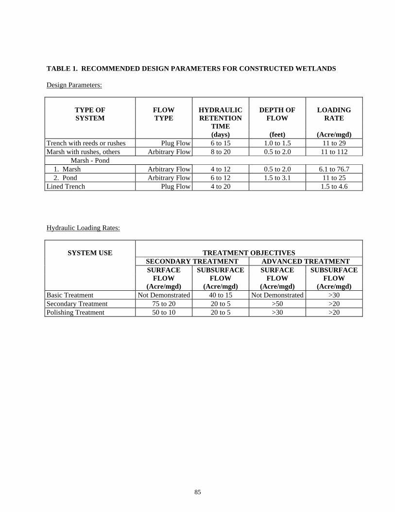
TABLE 1. RECOMMENDED DESIGN PARAMETERS FOR CONSTRUCTED WETLANDS Design Parameters:
TYPE OF FLOW HYDRAULIC DEPTH OF LOADING SYSTEM TYPE RETENTION FLOW RATE
TIME (days) (feet) (Acre/mgd)
Trench with reeds or rushes Plug Flow 6 to 15 1.0 to 1.5 11 to 29 Marsh with rushes, others Arbitrary Flow 8 to 20 0.5 to 2.0 11 to 112
Marsh - Pond 1. Marsh Arbitrary Flow 4 to 12 0.5 to 2.0 6.1 to 76.7 2. Pond Arbitrary Flow 6 to 12 1.5 to 3.1 11 to 25 Lined Trench Plug Flow 4 to 20 1.5 to 4.6 Hydraulic Loading Rates:
SYSTEM USE TREATMENT OBJECTIVES SECONDARY TREATMENT ADVANCED TREATMENT SURFACE SUBSURFACE SURFACE SUBSURFACE FLOW FLOW FLOW FLOW (Acre/mgd) (Acre/mgd) (Acre/mgd) (Acre/mgd)
Basic Treatment Not Demonstrated 40 to 15 Not Demonstrated >30 Secondary Treatment 75 to 20 20 to 5 >50 >20 Polishing Treatment 50 to 10 20 to 5 >30 >20
85
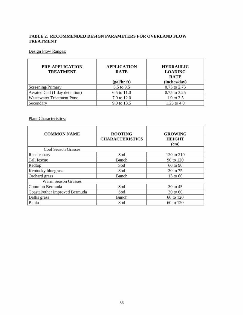
TABLE 2. RECOMMENDED DESIGN PARAMETERS FOR OVERLAND FLOW TREATMENT Design Flow Ranges:
PRE-APPLICATION APPLICATION HYDRAULIC
TREATMENT RATE LOADING RATE (gal/hr ft) (inches/day)
Screening/Primary 5.5 to 9.5 0.75 to 2.75 Aerated Cell (1 day detention) 6.5 to 11.0 0.75 to 3.25 Wastewater Treatment Pond 7.0 to 12.0 1.0 to 3.5 Secondary 9.0 to 13.5 1.25 to 4.0 Plant Characteristics:
COMMON NAME ROOTING GROWING
CHARACTERISTICS HEIGHT (cm)
Cool Season Grasses Reed canary Sod 120 to 210 Tall fescue Bunch 90 to 120 Redtop Sod 60 to 90 Kentucky bluegrass Sod 30 to 75 Orchard grass Bunch 15 to 60
Warm Season Grasses Common Bermuda Sod 30 to 45 Coastal/other improved Bermuda Sod 30 to 60 Dallis grass Bunch 60 to 120 Bahia Sod 60 to 120
86
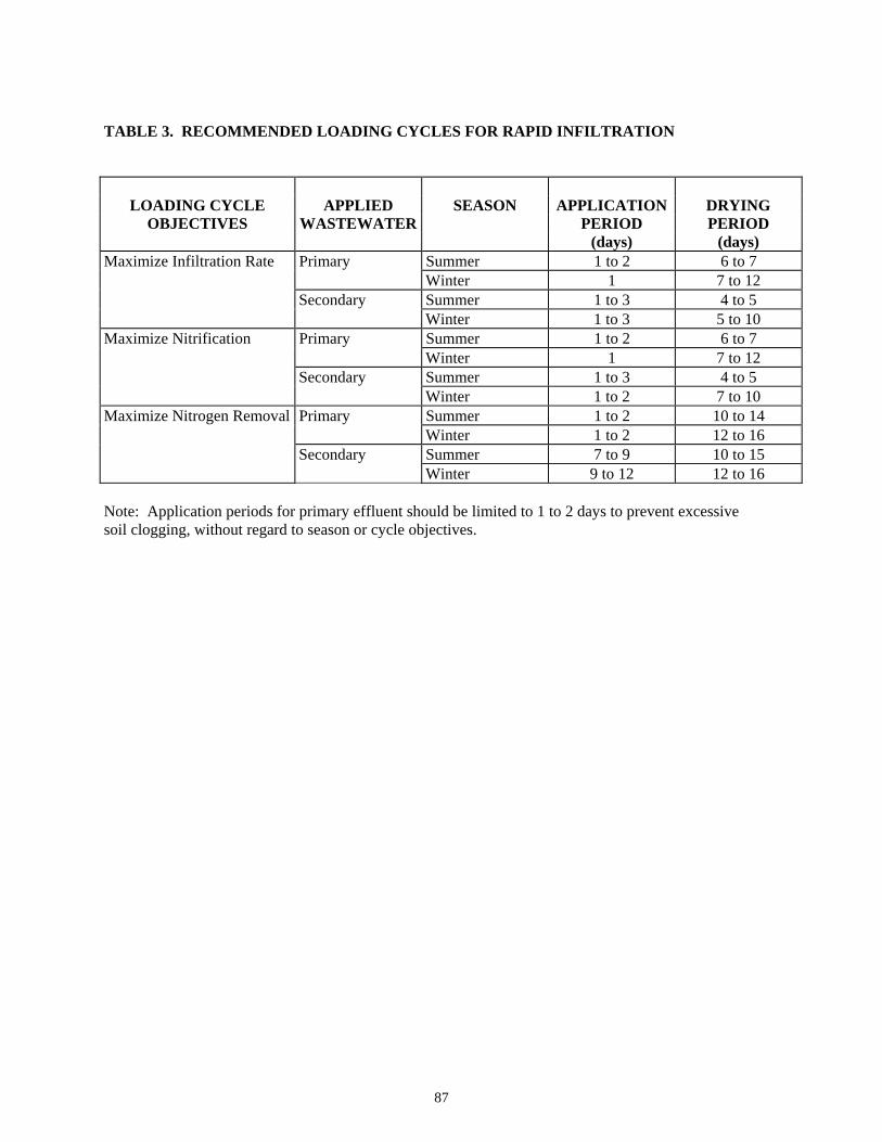
TABLE 3. RECOMMENDED LOADING CYCLES FOR RAPID INFILTRATION
LOADING CYCLE APPLIED SEASON APPLICATION DRYING
OBJECTIVES WASTEWATER PERIOD PERIOD (days) (days)
Maximize Infiltration Rate Primary Summer 1 to 2 6 to 7 Winter 1 7 to 12 Secondary Summer 1 to 3 4 to 5 Winter 1 to 3 5 to 10 Maximize Nitrification Primary Summer 1 to 2 6 to 7 Winter 1 7 to 12 Secondary Summer 1 to 3 4 to 5 Winter 1 to 2 7 to 10 Maximize Nitrogen Removal Primary Summer 1 to 2 10 to 14 Winter 1 to 2 12 to 16 Secondary Summer 7 to 9 10 to 15 Winter 9 to 12 12 to 16 Note: Application periods for primary effluent should be limited to 1 to 2 days to prevent excessive soil clogging, without regard to season or cycle objectives.
87
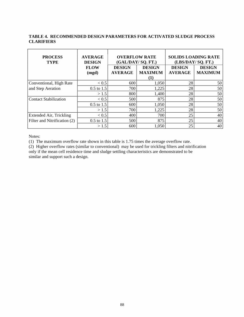
TABLE 4. RECOMMENDED DESIGN PARAMETERS FOR ACTIVATED SLUDGE PROCESS CLARIFIERS
PROCESS AVERAGE
TYPE DESIGN OVERFLOW RATE (GAL/DAY/ SQ. FT.)
SOLIDS LOADING RATE (LBS/DAY/ SQ. FT.)
FLOW DESIGN DESIGN DESIGN DESIGN (mgd) AVERAGE MAXIMUM AVERAGE MAXIMUM (1)
Conventional, High Rate < 0.5 600 1,050 28 50and Step Aeration 0.5 to 1.5 700 1,225 28 50 > 1.5 800 1,400 28 50Contact Stabilization < 0.5 500 875 28 50 0.5 to 1.5 600 1,050 28 50 > 1.5 700 1,225 28 50Extended Air, Trickling < 0.5 400 700 25 40Filter and Nitrification (2) 0.5 to 1.5 500 875 25 40 > 1.5 600 1,050 25 40 Notes: (1) The maximum overflow rate shown in this table is 1.75 times the average overflow rate. (2) Higher overflow rates (similar to conventional) may be used for trickling filters and nitrification only if the mean cell residence time and sludge settling characteristics are demonstrated to be similar and support such a design.
88
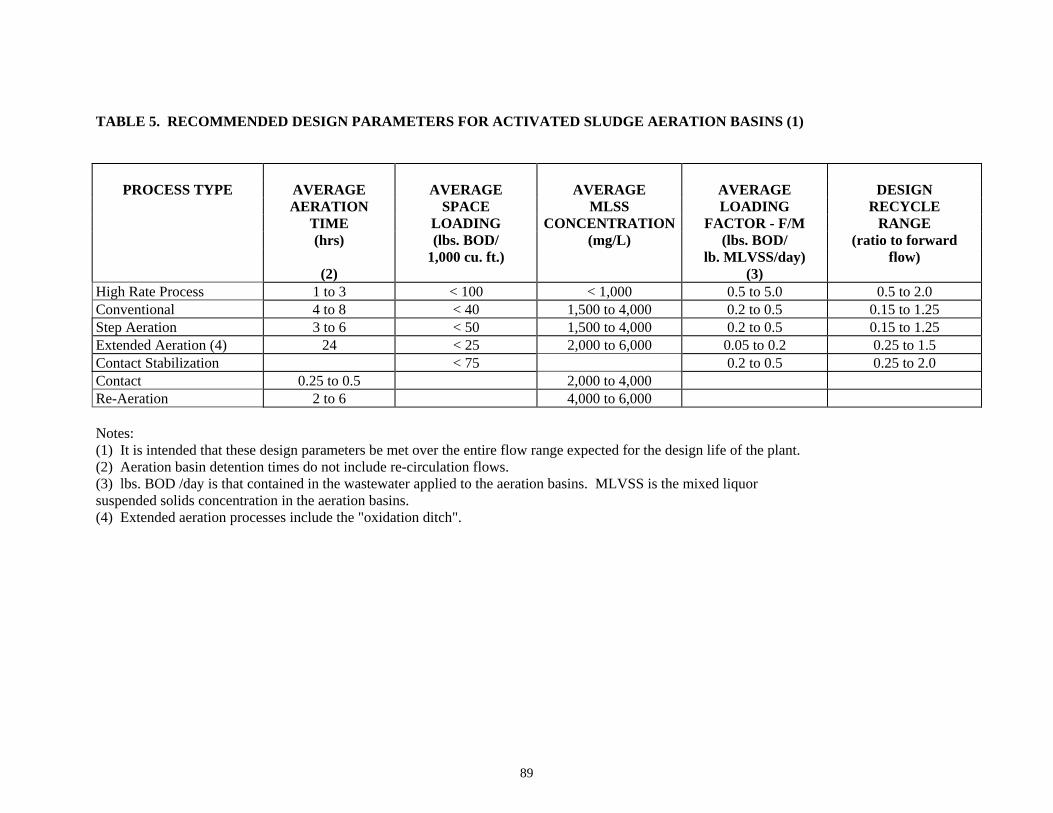
TABLE 5. RECOMMENDED DESIGN PARAMETERS FOR ACTIVATED SLUDGE AERATION BASINS (1)
PROCESS TYPE
AVERAGE LOADING
FACTOR - F/M (lbs. BOD/
lb. MLVSS/day)
DESIGN RECYCLE
RANGE (ratio to forward
flow)
AVERAGE AERATION
TIME (hrs)
(2)
AVERAGE SPACE
LOADING (lbs. BOD/
1,000 cu. ft.)
AVERAGE MLSS
CONCENTRATION(mg/L)
(3) High Rate Process 1 to 3 < 100 < 1,000 0.5 to 5.0 0.5 to 2.0 Conventional 4 to 8 < 40 1,500 to 4,000 0.2 to 0.5 0.15 to 1.25 Step Aeration 3 to 6 < 50 1,500 to 4,000 0.2 to 0.5 0.15 to 1.25 Extended Aeration (4) 24 < 25 2,000 to 6,000 0.05 to 0.2 0.25 to 1.5 Contact Stabilization < 75 0.2 to 0.5 0.25 to 2.0 Contact 0.25 to 0.5 2,000 to 4,000 Re-Aeration 2 to 6 4,000 to 6,000 Notes: (1) It is intended that these design parameters be met over the entire flow range expected for the design life of the plant. (2) Aeration basin detention times do not include re-circulation flows. (3) lbs. BOD /day is that contained in the wastewater applied to the aeration basins. MLVSS is the mixed liquor suspended solids concentration in the aeration basins. (4) Extended aeration processes include the "oxidation ditch".
89
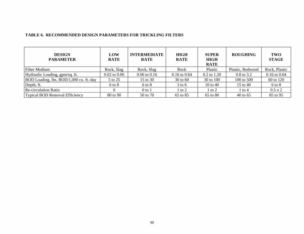
TABLE 6. RECOMMENDED DESIGN PARAMETERS FOR TRICKLING FILTERS
HIGH ROUGHING TWO DESIGN PARAMETER
LOW RATE
INTERMEDIATE RATE RATE STAGE
RATE
SUPER HIGH
Filter Medium Rock, Slag Rock, Slag Rock Plastic Plastic, Redwood Rock, Plastic Hydraulic Loading, gpm/sq. ft. 0.02 to 0.06 0.06 to 0.16 0.16 to 0.64 0.2 to 1.20 0.8 to 3.2 0.16 to 0.64 BOD Loading, lbs. BOD/1,000 cu. ft.-day 5 to 25 15 to 30 30 to 60 30 to 100 100 to 500 60 to 120 Depth, ft. 6 to 8 6 to 8 3 to 6 10 to 40 15 to 40 6 to 8 Re-circulation Ratio 0 0 to 1 1 to 2 1 to 2 1 to 4 0.5 o 2 Typical BOD Removal Efficiency 80 to 90 50 to 70 65 to 85 65 to 80 40 to 65 85 to 95
90
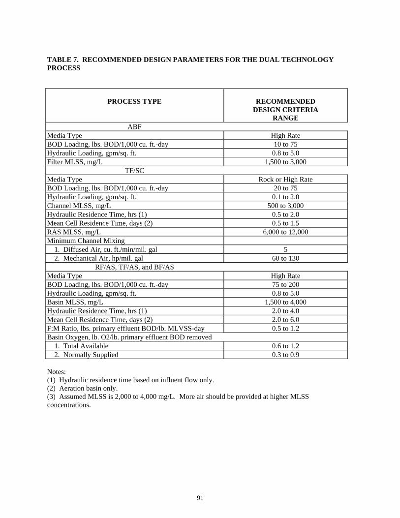
TABLE 7. RECOMMENDED DESIGN PARAMETERS FOR THE DUAL TECHNOLOGY PROCESS
PROCESS TYPE RECOMMENDED
DESIGN CRITERIA RANGE
ABF Media Type High Rate BOD Loading, lbs. BOD/1,000 cu. ft.-day 10 to 75 Hydraulic Loading, gpm/sq. ft. 0.8 to 5.0 Filter MLSS, mg/L 1,500 to 3,000
TF/SC Media Type Rock or High Rate BOD Loading, lbs. BOD/1,000 cu. ft.-day 20 to 75 Hydraulic Loading, gpm/sq. ft. 0.1 to 2.0 Channel MLSS, mg/L 500 to 3,000 Hydraulic Residence Time, hrs (1) 0.5 to 2.0 Mean Cell Residence Time, days (2) 0.5 to 1.5 RAS MLSS, mg/L 6,000 to 12,000 Minimum Channel Mixing 1. Diffused Air, cu. ft./min/mil. gal 5 2. Mechanical Air, hp/mil. gal 60 to 130
RF/AS, TF/AS, and BF/AS Media Type High Rate BOD Loading, lbs. BOD/1,000 cu. ft.-day 75 to 200 Hydraulic Loading, gpm/sq. ft. 0.8 to 5.0 Basin MLSS, mg/L 1,500 to 4,000 Hydraulic Residence Time, hrs (1) 2.0 to 4.0 Mean Cell Residence Time, days (2) 2.0 to 6.0 F:M Ratio, lbs. primary effluent BOD/lb. MLVSS-day 0.5 to 1.2 Basin Oxygen, lb. O2/lb. primary effluent BOD removed 1. Total Available 0.6 to 1.2 2. Normally Supplied 0.3 to 0.9 Notes: (1) Hydraulic residence time based on influent flow only. (2) Aeration basin only. (3) Assumed MLSS is 2,000 to 4,000 mg/L. More air should be provided at higher MLSS concentrations.
91


![CONCRETE FLOOR SLABS ON GRADE SUBJECTED TO HEAVY …civil.colorado.edu/~silverst/cven4830/design_of_Slabs[1].pdfconcrete floor slabs on grade subjected to heavy loads depart ments](https://img.pdfslide.us/doc/110x75/5f2fc07209e2f603340c5c0d/concrete-floor-slabs-on-grade-subjected-to-heavy-civil-silverstcven4830designofslabs1pdf.jpg)


![CONCRETE FLOOR SLABS ON GRADE SUBJECTED TO HEAVY LOADSceae.colorado.edu/~silverst/cven4830/design_of_Slabs[1].pdf · concrete floor slabs on grade subjected to heavy loads ... concrete](https://img.pdfslide.us/doc/110x75/5a796a617f8b9a770a8b9064/concrete-floor-slabs-on-grade-subjected-to-heavy-silverstcven4830designofslabs1pdfconcrete.jpg)