Embed Size (px)
Citation preview
U.S. Department of Transports tion
Publication No. FHWA-SA-94-072
November 1994
Federal Highway Administration
Surface Xeha bil itation Techniques
Design, Construction, and Performance of Micro-surf acing
Instructor's Guide
Office of Engineering Office of Technology Applications 400 Seventh Street, SW. Washington, D.C. 20590
~nnovation Through Partnerships
Archive
d
Notice
This document is disseminated under the sponsorship of the Department of Transportation in the interest of information exchange. The United States Government assumes no liability for its contents or use thereof. The United States Government does not endorse products or manufacturers. Trademarks or manufacturers' names appear herein only because they are considered essential to the object of this document.
Archive
d
T echnical Report Documentation Page
Form DOT F 1700.7 (8-72)
a
Reproduction of tompletod poge outhori xed
1. Report No.
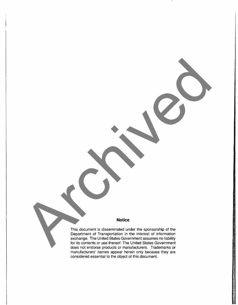
FHWA-SA-94-072
2 Government Access~on No. 3. R e c ~ ~ ~ e n t ' s Cotolog NO. 1
4 . Title ond Svbt~* le
Surface Rehabi 1 i t a t i o n Techniques: Design, Construct ion, and Performance o f Micro-Surfacing, I n s t r u c t o r f s Guide
7. Author s
Hassan ~ a z a , p~ 9. P r r f o r m ~ n ~ Organlzo*lon Nome ond Address
Federal Highway Admin is t ra t ion O f f i c e o f Engineering, Pavement D i v i s i o n (HNG-42; 400 Seventh St ree t , SW. Washington, -- D.C. 20590
i 12. Sponrorrn~ Agency Nome ond Address
Federal Highway Admini s t r a t i o n O f f i c e o f Engi nee r i ng/Off i ce o f Techno1 ogy Appl i c a t i ons 400 Seventh St ree t , SW.
5 . Report Dote
November 1994 6 . Per iorm~ng Orgon~ro t~on Code
8. Pcrformrng Orgon~zotlon Report No.
10. Work U n ~ t NO. (TRAIS)
1 1 . Controct OI Gront NO.
13. Type o f Report and P e r ~ o d Covered
F i n a l Report ,
14. Sponsor~ng Agency code
I Washington, D.C. 20590 15 Svpplernentory Notes
L
16 Abstroct
This i n s t r u c t o r ' s guide i s designed f o r a 2 - to -4 hour l ong workshop on design, cons t ruc t ion , and performance o f micro-sur fac ing. Th is workshop w i 11 be usefu l t o FHWA, State, and l o c a l highway agency engineers who r e q u i r e know1 edge o f mic ro-sur fac ing . Micro-sur fac ing cons is ts o f polymer-modif ied asphal t emulsion, 100 percent crushed aggregate, minera l f i l l e r , water, and f i e l d c o n t r o l a d d i t i v e s as needed. Mic ro-sur fac ing i s p r i m a r i l y used t o improve sur face f r i c t i o n and t o f i l l wheel r u t s . When p rope r l y designed and constructed, i t has shown good performance f o r 4 - to -7 years. Since mic ro-sur fac ing i s app l ied i n a t h i n layer , 10-to-15 mm, i t s use should be l i m i t e d t o s t r u c t u r a l l y sound pavements.
The one unresolved engineering issue concerning t h i s technology i s t h e l a c k o f standard mix ture design t e s t procedures. Although t h e cu r ren t t e s t i n g procedures have r e s u l t e d i n m i c ro -su r fac i ng systems t h a t have general l y provided good performance, there i s a need t o f u r t h e r improve t h e e x i s t i n g t e s t procedures and ad jus t design standards t o b e t t e r r e f l e c t t he e f f e c t o f var ious mix ture components. Improved mix ture design procedures and standards and Sta te acceptance c r i t e r i a w i l l f u r t h e r enhance the acceptance o f t h i s technology by t h e highway community.
I
17. K~~ Words
Micro-Surfacing, Polymer Mod i f ied Emulsion, Add i t i ve , Textur ing, Skid Resistance, Rut, R e h a b i l i t a t i o n
Dlrtributlon NO r e s t r i c t i ons . ~h i s document i s a v a i l a b l e i n a l i m i t e d supply from t h e FHWA RD&T Report Center, HRD-11 6300 Georgetown Pike, McLean,VA I 22101-2296
22. P r ice 19. Socurlty C l o r s ~ f . (o f thrr report)
Uncl ass i f i e d 20. k c u r i t y Closrif . (of this pogo)
Unc lass i f i ed
21. No. of Pager
Archive
d

Archive
d
This instructor's guide is developed to facilitate a slide presentation on design, construction, and performance of micro-surfacing. This guide is based primarily on information from publication State of the Practice - Design, construction, and Performance of Micro-surfacing (FHWA-SA-94-051). The state of the practice publication was developed using a variety of sources including: literature, field reviews of existing and ongoing projects, discussion with the user agencies, and review of materials and manufacturing facilities. Possible audiences for this presentation include engineers and managers of Federal, State, and local highway agencies. The presentation is also useful for members of industry.
The Guide is organized into two sections. The first section provides general information on the description, composition, and uses of micro-surfacing along with definition of some common terms. The second section provides information on design, construction, performance, and cost of micro-surfacing .
This guide is set up in a traditional script format-with visuals given on one side and the corresponding text listed in the other column. The text is specifically designed to be a resource to the instructor and attendees. Leaders (. . .) indicate where the presenter should read directly from the slide.
Along with this guide and the slides, the presenter will need the following equipment and materials to complete the presentation:
Slide Projector a Screen a Carousel
Extension cord (check facilities to see if necessary) Sign-in sheet
a Handouts
The instructor must handle any preliminary "housekeeping" chores, such as handing out the schedule and instructor's biodata, distributing the necessary handouts including sign off sheet, and determining audience interest. The instructor should also briefly introduce himself or herself, and should have the class participants introduce themselves. Ask each participant to give their name, employer, and job responsibilities. Any background information on the participants will also help instructors structure their presentations so that they will be well received. Arch
ived

Archive
d

Table of Contents
Overview ................................................................................... 1
Mixture Design ............................................................................ 4
Construction ............................................................................. 12
Performance .............................................................................. 30
Costs .......................................................................................... 33
Summary and Needs ................................................................ 34
Archive
d

Archive
d

OVERVIEW
PRESENTATION
Design H Construction H Performance
DESCRIPTION
H A Thin (1 0 to 15 mm) Surface Paving System Developed in Europe in 1970s Introduced in the United States in 1 980
COMPOSITION
H Aggregate H Polymer-modified Emulsion
Water H Mineral Filler H Field Control Additive
.
This presentation is an overview of ...
The information contained in this presentation is based on a detailed literature search, field reviews of numerous existing and ongoing projects, discussions with State and industry representatives, and visits to materials laboratories and equipment manufacturing facilities.
Since then, many States have used this treatment on their moderate to heavy volume roads. Most of the micro-surfacing systems are known by the generic name (i.e., micro-surfacing). However, some systems
. are commonly known by trade names such as Ralumac, Macroseal, and Durapave. Major differences among the various systems are due to the types of emulsifiers and polymers used.
Micro-surfacing is basically a slurry seal with a polymer-modified binder and higher quality materials. It consists of.. .
These ingredients are mixed and applied in the field using a mobile mixing unit. Compared to hot mix asphalt which is workable when hot and hardens upon cooling, micro-surfacing hardens through an electro- chemical process and by the loss of water from the system. Archive
d
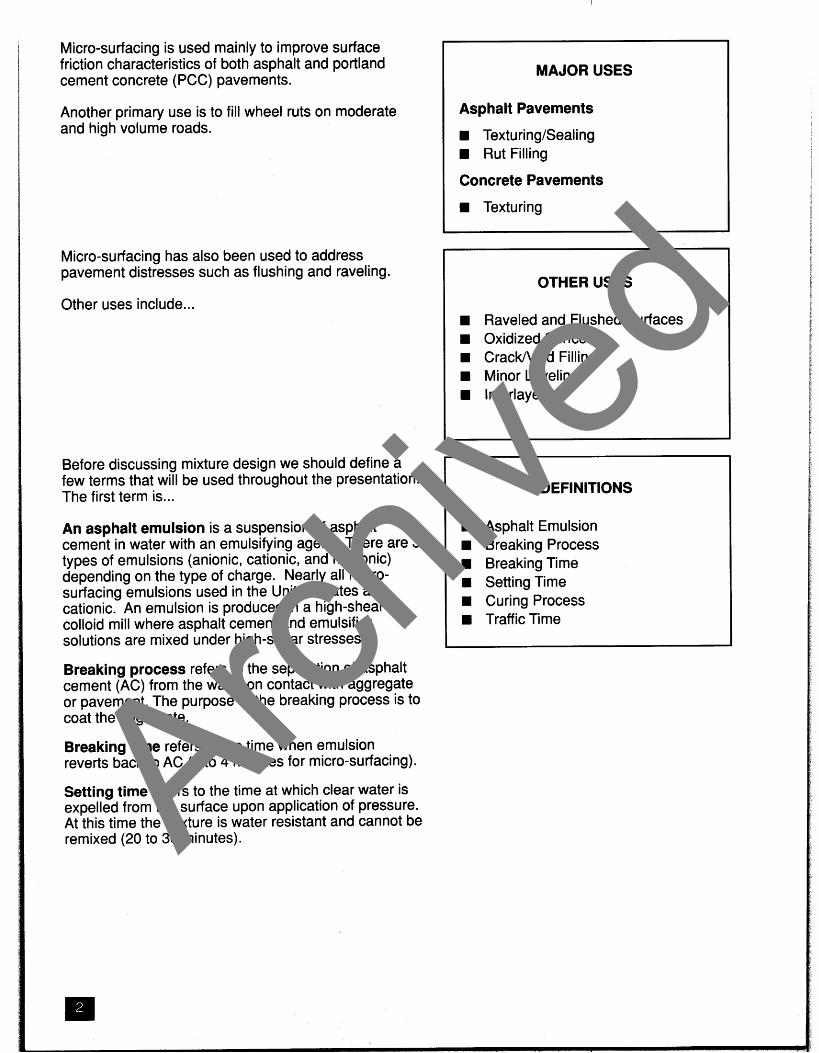
Micro-surfacing is used mainly to improve surface friction characteristics of both asphalt and portland cement concrete (PCC) pavements.
Another primary use is to fill wheel ruts on moderate and high volume roads.
MAJOR USES
Asphalt Pavements
H TexturingISealing H Rut Filling
Concrete Pavements
H Texturing
Micro-surfacing has also been used to address pavement distresses such as flushing and raveling.
Other uses include ...
Before discussing mixture design we should define a few terms that will be used throughout the presentation. The first term is ...
An asphalt emulsion is a suspension of asphalt cement in water with an emulsifying agent. There are 3 types of emulsions (anionic, cationic, and nonionic) depending on the type of charge. Nearly all micro- surfacing emulsions used in the United States are cationic. An emulsion is produced in a high-shear colloid mill where asphalt cement and emulsifier solutions are mixed under high-shear stresses.
Breaking process refers to the separation of asphalt cement (AC) from the water on contact with aggregate or pavement. The purpose of the breaking process is to coat the aggregate.
Breaking time refers to the time when emulsion reverts back to AC (2 to 4 minutes for micro-surfacing).
Setting time refers to the time at which clear water is expelled from the surface upon application of pressure. At this time the mixture is water resistant and cannot be remixed (20 to 30 minutes).
OTHER USES
H Raveled and Flushed Surfaces H Oxidized Surfces
CrackIVoid Filling H Minor Leveling H Interlayer
DEFINITIONS
H Asphalt Emulsion H Breaking Process H Breaking Time
Setting Time H Curing Process H Traffic Time
Archive
d

High Volume Roads
5,000 vehicles per lane
or
2 500,000 80 kN ESALsIyr
Curing process is the complete removal of water from the mixture (7 to 14 days).
Traffic time refers to the time when traffic can be allowed on the newly placed surface without damaging it (usually one hour).
For the purpose of this presentation, high volume roads are defined as roads that carry more than ...
Archive
d
MIXTURE DESIGN
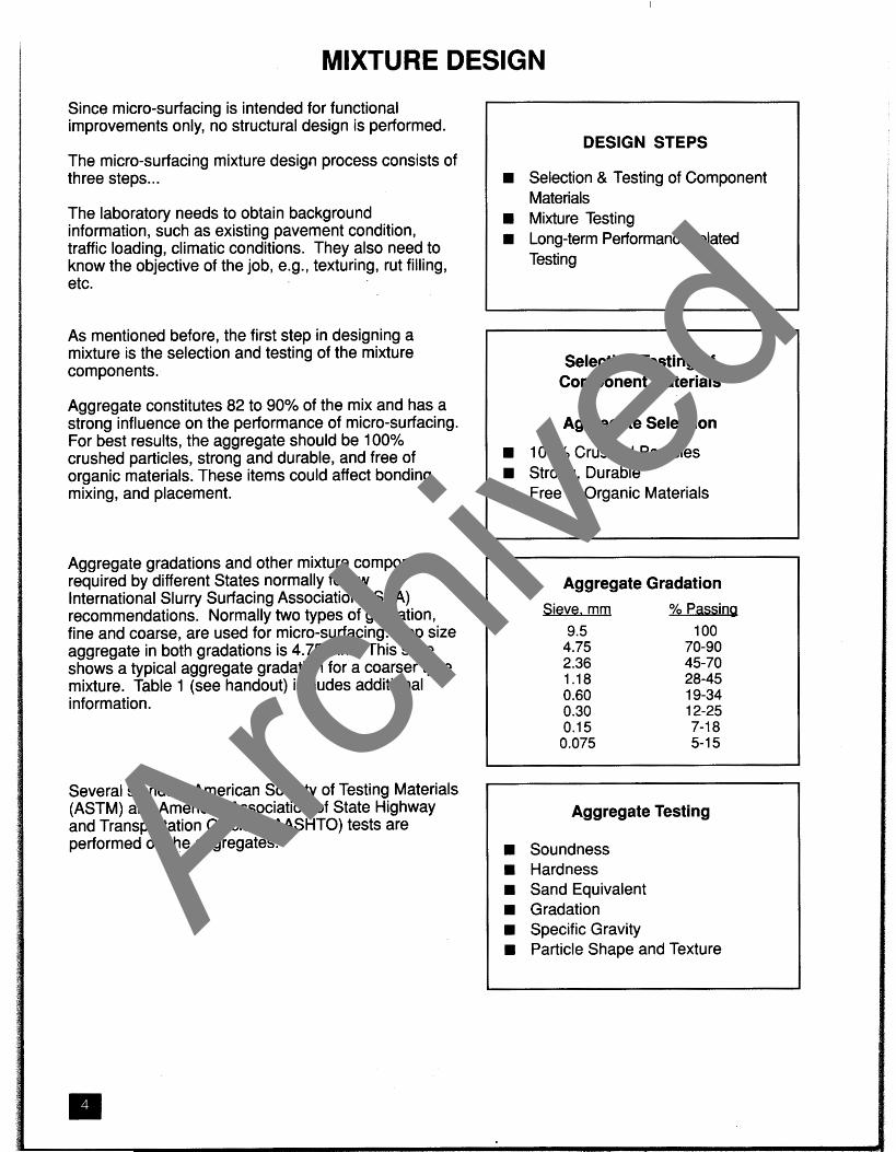
Since micro-surfacing is intended for functional improvements only, no structural design is performed.
The micro-surfacing mixture design process consists of three steps. ..
The laboratory needs to obtain background information, such as existing pavement condition, traffic loading, climatic conditions. They also need to know the objective of the job, e.g., texturing, rut filling, etc.
As mentioned before, the first step in designing a mixture is the selection and testing of the mixture components.
Aggregate constitutes 82 to 90% of the mix and has a strong influence on the performance of micro-surfacing. For best results, the aggregate should be 100% crushed particles, strong and durable, and free of organic materials. These items could affect bonding, mixing, and placement.
Aggregate gradations and other mixture components required by different States normally follow International Slurry Surfacing Association (ISSA) recommendations. Normally two types of gradation, fine and coarse, are used for micro-surfacing. Top size aggregate in both gradations is 4.75 mm. This slide shows a typical aggregate gradation for a coarser type mixture. Table 1 (see handout) includes additional information.
Several standard American Society of Testing Materials (ASTM) and American Association of State Highway and Transportation Officials (AASHTO) tests are performed on the aggregates.
DESIGN STEPS
w Selection & Testing of Component Materials Mixture Testing
w Long-term Performance-related Testing
SelectionlTesting of Component Materials
Aggregate Selection
w 100% Crushed Particles w Strong, Durable
Free of Organic Materials
Aggregate Gradation Sieve. mm % Passing
9.5 100 4.75 70-90 2.36 45-70 1.18 28-45 0.60 19-34 0.30 12-25 0.1 5 7-1 8 0.075 5-1 5
Aggregate Testing
w Soundness Hardness Sand Equivalent Gradation Specific Gravity
w Particle Shape and Texture Arch
ived
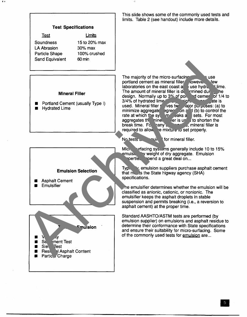
Test Specifications
IkSl Limib
Soundness 15 to 20% max LA Abrasion 30% max Particle Shape 100% crushed Sand Equivalent 60 min
Mineral Filler
Portland Cement (usually Type I) Hydrated Lime
Emulsion Selection
Asphalt Cement Emulsifier
Tests on Emulsion -
Viscosity Settlement Test Sieve Test Residual Asphalt Content Particle Charge
This slide shows some of the commonly used tests and limits. Table 2 (see handout) include more details.
The majority of the micro-surfacing systems use portland cement as mineral filler. However, a few laboratories on the east coast also use hydrated lime. The amount of mineral filler is determined during the design. Normally up to 3% of portland cement or 114 to 314% of hydrated lime by dry weight of aggregate is used. Mineral filler serves two major purposes: (a) to minimize aggregate segregation and (b) to control the rate at which the system breaks and sets. For most aggregates the mineral filler is used to shorten the break time. For many aggregates, mineral filler is required to allow the mixture to set properly.
No tests are required for mineral filler.
Micro-surfacing systems generally include 1 0 to 1 5% emulsion by weight of dry aggregate. Emulsion properties depend a great deal on. ..
Typically, emulsion suppliers purchase asphalt cement that meets the State higway agency (SHA) specifications.
The emulsifier determines whether the emulsion will be classified as anionic, cationic, or nonionic. The emulsifier keeps the asphalt droplets in stable suspension and permits breaking (i.e., a reversion to asphalt cement) at the proper time.
Standard AASHTOIASTM tests are performed (by emulsion supplier) on emulsions and asphalt residue to determine their conformance with State specifications and ensure their suitability for micro-surfacing. Some of the commonly used tests for emulsion are ... Archive
d
I Commonly used tests for asphalt residue include ...
Table 3 (see handout) shows emulsion and asphalt residue tests required by some of the States.
Micro-surfacing systems normally include 3 to 4% polymers by weight of asphalt residue. Polymers are typically credited with increasing the stiffness, reducing the temperature susceptibilty of the binder and improving adhesion.
State specifications do not require any tests on polymers. The amount and suitability of polymers are currently determined by viscosity and softening point tests on the asphalt cements.
Currently there is no restriction on the type of polymer that can be used in micro-surfacing mixtures. Natural latex is the most commonly used polymer. However, other polymers such as SBS, SBR, and EVA are also used.
Typically 4 to 12% water by weight of dry aggregate is used in micro-surfacing. Mixtures with low moisture content may be too stiff to spread and will adhere poorly to the existing pavement. On the other hand, mixtures containing too much water may segregate.
f Any potable water can be used in micro-surfacing. Quantity of water is more critical than quality of water.
Tests on Asphalt Residue
Absolute Viscosity Penetration
a Softening Point Ductility
Polymer
D Reduced Temperature Susceptibility lmproved Stiffness
w Improved Adhesion
No Tests Are Required
Polymer Type
Rubber Natural Latex (natural rubber) Synthetic Latex (SBR) Block Co-polymer (SBS) Reclaimed Rubber (old tires)
Plastic (polyethylene, poly- propylene, EVA, PVC)
Combination of Rubber and Plastic
Water
Determines the Mixture Consistency Potable Quantity is Important Archive
d
Field control ~ d d itive
Affects Break Time Type or Amount not Specified
Mixture Testing
Mixing & Application Characteristics H Water and Filler Requirements
Asphalt Cement Requirements
The amount of additive ranges from 0 to 2% by the volume of emulsion. Although the additive may be used to either retard or accelerate the break time, it is commonly used to retard the break time.
Specifications do not specify the type or amount of additive that can be added in the field. Additive used in micro-surfacing is the emulsifier used to make the emulsion. Its cost varies from $2.60 to $5.20 per liter.
Mixture testing is performed to determine mixture consistency, water and filler requirements, and optimum asphalt content.
Tests for Mixing and Application
Mixing Test Adhesion Test
H Cohesion Test
As a first step, a number of specimens are prepared and are subjected to empirical testing. Mixing tests are performed to determine (1) if the primary components, aggregate and emulsion, are compatible (there is good adhesion between them), (2) if a mineral filler and additive are needed and, if so, in what quantity, and (3) the range of water content over which homogeneous mixtures can be obtained. Mixture consistency is extremely important for micro- surfacing.
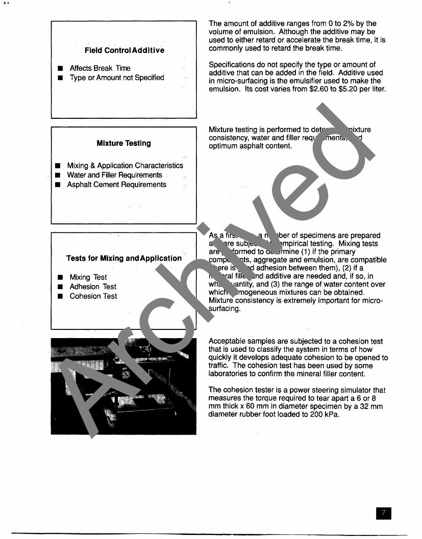
Acceptable samples are subjected to a cohesion test that is used to classify the system in terms of how quickly it develops adequate cohesion to be opened to traffic. The cohesion test has been used by some laboratories to confirm the mineral filler content.
The cohesion tester is a power steering simulator that measures the torque required to tear apart a 6 or 8 mm thick x 60 mm in diameter specimen by a 32 mm diameter rubber foot loaded to 200 kPa. Archive
d
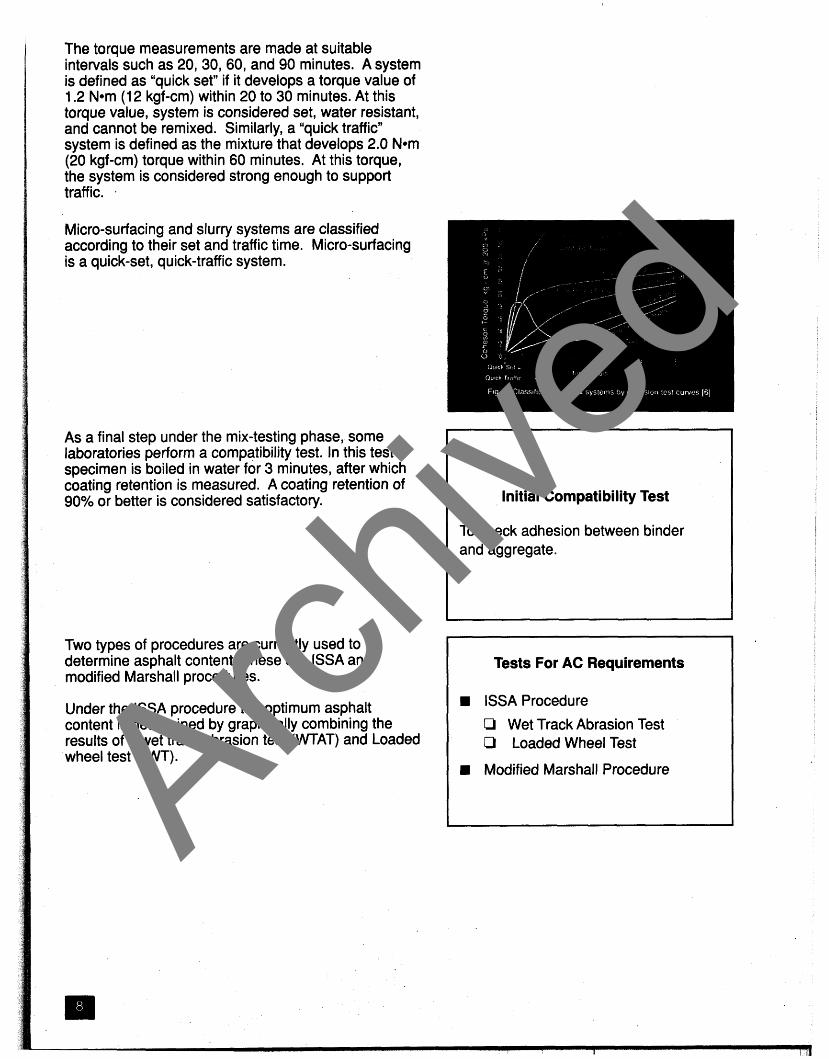
The torque measurements are made at suitable intervals such as 20, 30, 60, and 90 minutes. A system is defined as "quick set" if it develops a torque value of 1.2 Nom (1 2 kgf-cm) within 20 to 30 minutes. At this torque value, system is considered set, water resistant, and cannot be remixed. Similarly, a "quick traffic" system is defined as the mixture that develops 2.0 Nom (20 kgf-cm) torque within 60 minutes. At this torque, the system is considered strong enough to support traffic.
Micro-surfacing and slurry systems are classified according to their set and traffic time. Micro-surfacing
m is a quick-set, quick-traffic system.
As a final step under the mix-testing phase, some laboratories perform a compatibility test. In this test a specimen is boiled in water for 3 minutes, after which coating retention is measured. A coating retention of 90% or better is considered satisfactory.
Two types of procedures are currently used to determine asphalt content. These are ISSA and modified Marshall procedures.
Under the ISSA procedure the optimum asphalt content is determined by graphically combining the results of a wet track abrasion test (WTAT) and Loaded wheel test (LWT).
Initial Compatibility Test
To check adhesion between binder and aggregate.
Tests For AC Requirements
ISSA Procedure
Li Wet Track Abrasion Test O Loaded Wheel Test
Modified Marshall Procedure Archive
d

WTAT simulates wet abrasive conditions such as vehicle turning and breaking. In this test a cured sample 6 mm thick x 280 mm in diameter that has been soaked for an hour is immersed in a 25 'C water pan and is wet-abraded by a rotating weighted (2.3 kg) rubber hose for 5 minutes. The abraded sample is dried and weighed.
Asphalt content that results in a weight loss of 0.54 kglm2 or less is considered the minimum.
LWT is used to determine the maximum asphalt content that can be used without risk of mixture flushing. In this test a 50 mm wide x 375 mm long specimen of desired thickness is fastened to the mounting plate and is compacted with 1000, 57 kg cycles at 25 'C. At the end of compaction, the specimen is weighed, and a measured quantity of sand is spread on the sample. The LWT is repeated, and the sample is removed and weighed. The increase in weight is noted. If the sand adhesion is below 0.54 kg1 m2, mixture bleeding should not occur.
This graph shows determined by cor
how nbini
ltimum WTAT
asp1 and
ialt content is LWT results.
The Marshall procedure is the second method used for determining optimum asphalt content. This photo shows a typical Marshall apparatus used to determine the maximum load (stability value) the specimen will withstand before failure.
Since micro-surfacing is a cold mixture, the Marshall procedure has been modified to allow for air and low temperature drying (at least 3 days of air curing, 18-20 hours of drying in an oven at 60 'C before compaction). Under this procedure, several test specimens are prepared for combinations of aggregate and asphalt content. The initial asphalt contents are based on the voids in total mix of about 4.5 to 5.5 percent. Stability, flow value, and bulk specific gravity are measured.
Archive
d

Final step in the mixture design procedure is field simulation testing. Two tests are used by many of the laboratories. These are ...
Besides determining asphalt content, LWT may also be used to determine the compaction characteristics of thicker micro-surfacing applications. Either a standard loaded wheel tester or a 3-track machine as shown in this slide can be used.
In this test, specimens are cast into test strips of 13 or 19 mm thick x 50 mm wide x 380 mm long. Test strips are measured and then compacted with 1000,57 kg LWT cycles at an ambient temperature of 21 'C. At the end of the test, the percentage of vertical displacement, lateral displacement, and compacted densities are determined. Limits of 10 to 12% vertical and 5% lateral displacements are normally used.
The Schulze-Breuer and Ruck (SB) test is run as a final check on the adhesion between binder and aggregate under wet conditions. In this test, a measured specimen is soaked for 6 days, weighed for absorption, and then wet tumbled in the SB machine's shuttle cylinders for 3600 cycles at 20 RPM. At the end of the test, specimen is weighed for abrasion loss. Abraded sample is further tested for integrity and adhesion (coating).
.
Performance-related Tests
Multilayer Loaded Wheel Test Schulze-Breuer and Ruck Test
Archive
d

Design Comments
Design is Still Evolving Sample Preparation is Still an Art Test Repeatability Not Assured Tests Need To be Standardized Design Values Need Adjustment Main Purpose is Compatibility lndustry is Reviewing Procedures
While a large number of projects have performed well, micro-surfacing design is still evolving and needs a number of refinements.
Sample preparation and consistency (amount of water and emulsion) have a significant influence on test results. Yet a reliable sample preparation procedure has not yet been perfected. Therefore, repeatability of tests is not assured.
Tests are not standardized by ASTM or AASHTO. Not all tests are used by all design laboratories.
Design standards were developed using limited material combinations and need adjustments based on additional testing.
The main purpose of all the design tests at this time is to determine the compatibility of the various materials.
Industry is trying to improve design procedures and adjust standards to reflect effect of various material combinations.
Archive
d
CONSTRUCTION
This part of the presentation will center on various construction-related aspects such as ...
Micro-surfacing should not be placed if either the I
pavement or air temperature is below 10 'C. If placed in cold temperatures, micro-surfacing may ravel and crack. If placed in very hot weather, the surface can I
break too fast, causing slow interior curing.
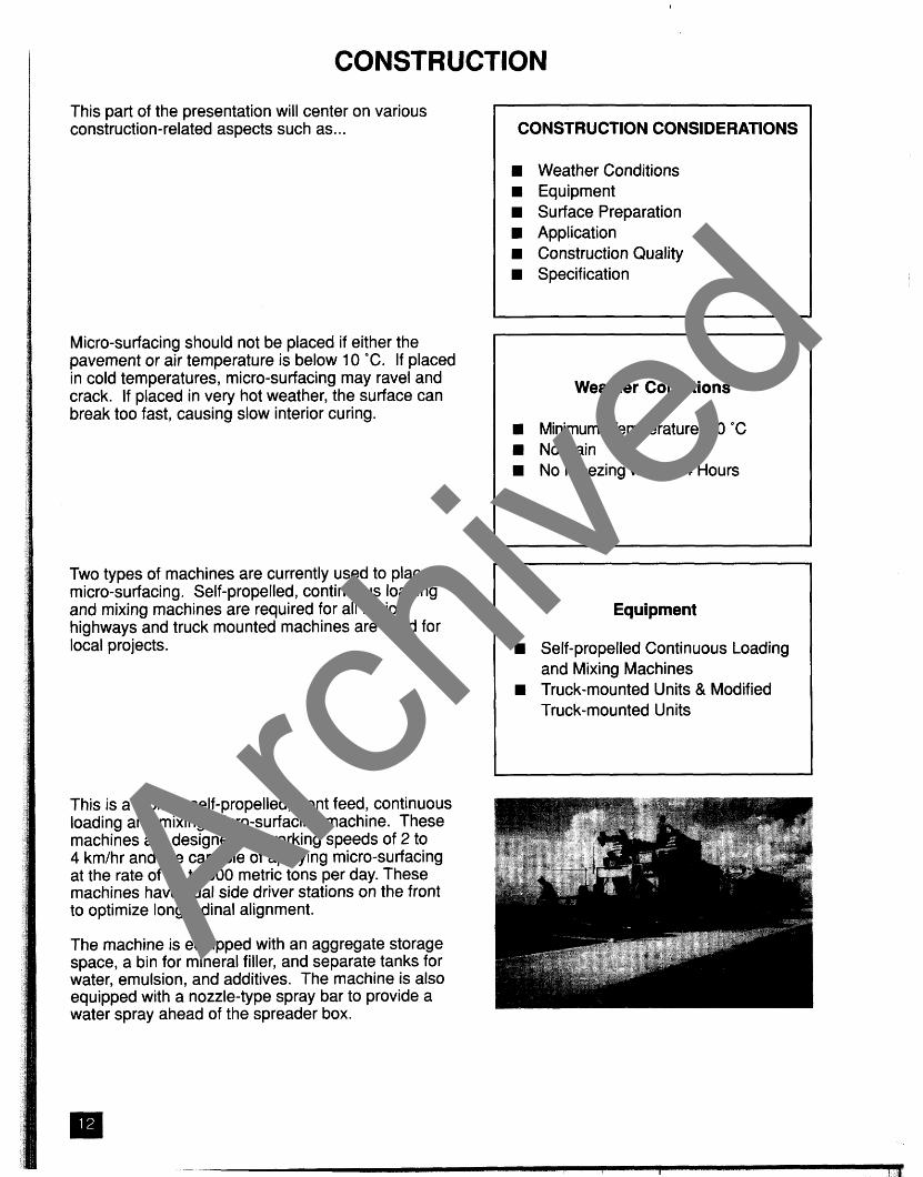
Two types of machines are currently used to place micro-surfacing. Self-propelled, continuous loading and mixing machines are required for all major highways and truck mounted machines are used for local projects.
This is a typical, self-propelled, front feed, continuous loading and mixing micro-surfacing machine. These machines are designed for working speeds of 2 to 4 kmlhr and are capable of applying micro-surfacing at the rate of up to 500 metric tons per day. These machines have dual side driver stations on the front to optimize longitudinal alignment.
The machine is equipped with an aggregate storage space, a bin for mineral filler, and separate tanks for water, emulsion, and additives. The machine is also equipped with a nozzle-type spray bar to provide a water spray ahead of the spreader box.
CONSTRUCTION CONSIDERATIONS
H Weather Conditions H Equipment
Surface Preparation Application Construction Quality Specification
Weather Conditions
Minimum Temperature, 10 'C No Rain
H No Freezing within 24 Hours
Equipment
H Self-propelled Continuous Loading and Mixing Machines
H Truck-mounted Units & Modified Truck-mounted Units
Archive
d

The machine is fitted with controls and meters to proportion and monitor properly the quantity of all components. The controls should be spot-checked prior to start of each project. Amounts of emulsion, aggregate, and mineral filler are fixed prior to placement operation, and only water and additive are changed (within limits) to obtain proper consistency and break time.
The machine controls should be calibrated at least once every construction season (preferably prior to each project).
The aggregate is received by to the storage area, and then conveyor belt.
a front hopper, delive fed to the mixer on a
The mixers are about 1 to 1.3 m long and are fitted with multibladed twin shafts to allow thorough mixing of materials.
This slide shows the entry of various materials into the mixer. Mineral filler is added to the aggregate just before it enters the mixer. Water and additives are combined and added to the aggregate as it falls into the mixer. These ingredients are mixed before the emulsion is introduced, usually at about the one-third point of the mixer. The materials are mixed for 5 to 10 seconds prior to discharge into the spreader box where they are mixed for another 5 to 15 seconds. Archive
d
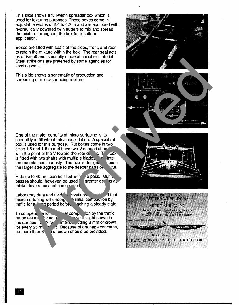
This slide shows a full-width spreader box which is used for texturing purposes. These boxes come in adjustable widths of 2.4 to 4.2 m and are equipped with hydraulically powered twin augers to mix and spread the mixture throughout the box for a uniform application.
Boxes are fitted with seals at the sides, front, and rear to retain the mixture within the box. The rear seal acts as strike-off and is usually made of a rubber material. Steel strike-offs are preferred by some agencies for leveling work.
This slide shows a schematic of production and spreading of micro-surfacing mixture.
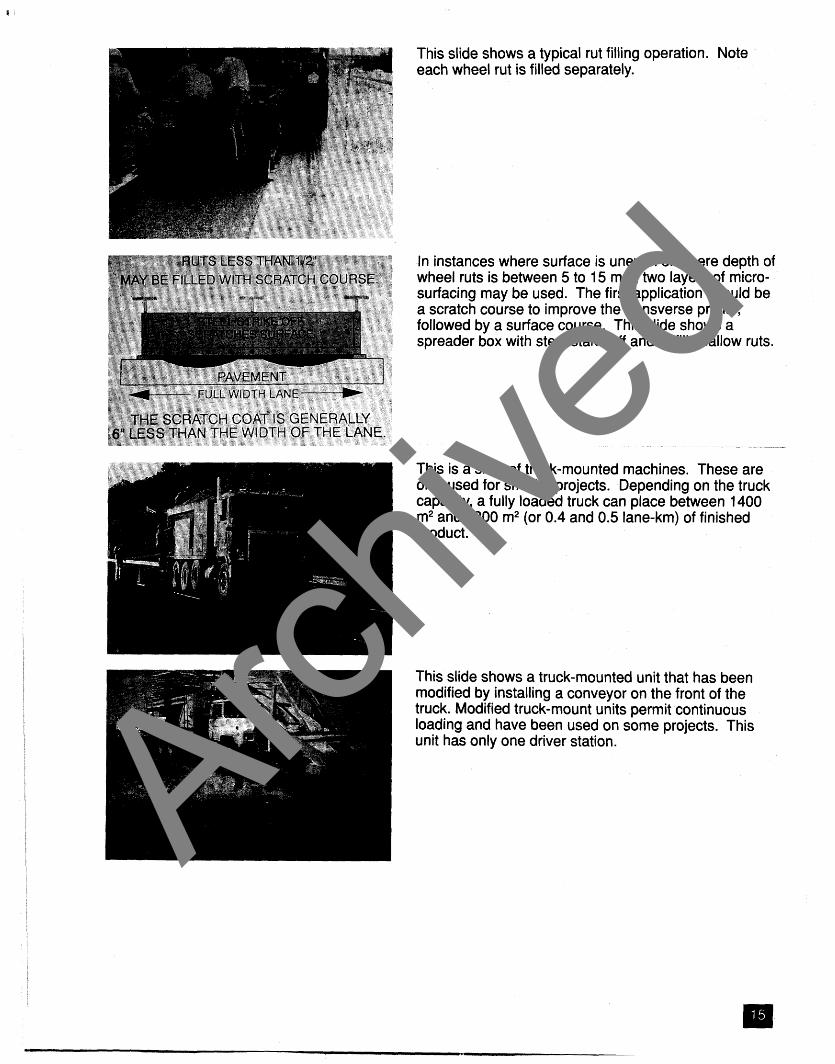
One of the major benefits of micro-surfacing is its capability to fill wheel ruts/consolidation. A special rut box is used for this purpose. Rut boxes come in two sizes 1.5 and 1.8 m and have two V-shaped chambers with the point of the V toward the rear of box. The box is fitted with two shafts with multiple blades to agitate the material continuously. The box is designed to push the larger size aggregate to the deeper parts of the rut.
Ruts up to 40 mm can be filled with one pass. Multiple passes should,' however, be used for greater depths as thicker layers may not cure properly.
Laboratory data and field observations have found that micro-surfacing will undergo an initial compaction by traffic for a short period before reaching a steady state.
To compensate for the initial compaction by the traffic, rut boxes may be adjusted to leave a slight crown in the surface. ISSA recommends adding 3 mm of crown for every 25 mm of rut. Because of drainage concerns, no more than 6 mm of crown should be provided. Arch
ived
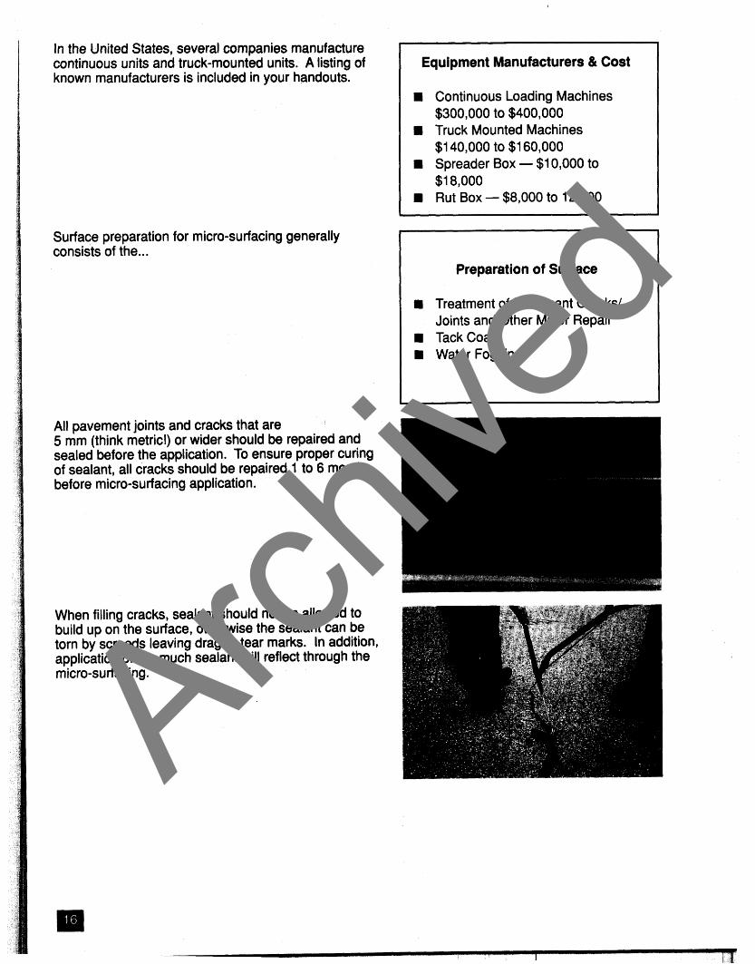
In instances where surface is uneven or where depth of wheel ruts is between 5 to 15 mm, two layers of micro- surfacing may be used. The first application should be a scratch course to improve the transverse profile, followed by a surface course. This slide shows a spreader box with steel stake off and to fill shallow ruts.
This is a slide of truck-mounted machines. These are only used for smaller projects. Depending on the truck capacity, a fully loaded truck can place between 1400 m2 and 1800 m2 (or 0.4 and 0.5 lane-km) of finished product.
This slide shows a truck-mounted unit that has been modified by installing a conveyor on the front of the truck. Modified truck-mount units permit continuous loading and have been used on some projects. This unit has only one driver station. Archive
d
In the United States, several companies manufacture continuous units and truck-mounted units. A listing of known manufacturers is included in your handouts.
Surface preparation for micro-surfacing generally consists of the ...
All pavement joints and cracks that are 5 mm (think metric!) or wider should be repaired and sealed before the application. To ensure proper curing of sealant, all cracks should be repaired 1 to 6 months before micro-surfacing application.
Equipment Manufacturers & Cost
Continuous Loading Machines $300,000 to $400,000 Truck Mounted Machines $1 40,000 to $1 60,000 Spreader Box - $1 0,000 to $1 8,000 Rut BOX - $8,000 to 12,000
Preparation of Surface
Treatment of Pavement Cracks/ Joints and Other Minor Repair Tack Coat Water Fogging
When filling cracks, sealant should not be allowed to build up on the surface, otherwise the sealant can be torn by screeds leaving drag or tear marks. In addition, application of too much sealant will reflect through the micro-surfacing .
I Archive
d

Tack Coat
All PCC Pavements Dry & Raveled Asphalt Pavements
This slide shows a drag mark caused by sealant build up on the surface.
A tack coat should be used on ... prior to application of micro-surfacing.
The tack coat will generally consist of diluted emulsion spray (i.e., one part asphalt emulsion and one to three parts water). It should be allowed to cure before application of micro-surfacing . A minimum curing period of 112 to 2 hours is normally required under favorable conditions. Slow setting emusions are normally used because rapid setting emulsions are prone to break on the aggregate surface, reducing the quantity of bitumen available for filling the voids and resulting in tire pick-up.
Tack coat is applied with a distributor truck fitted with a spray bar.
Tack coat application rate should be kept at 0.16 to 0.32 Vm2. Too much tack coat will bleed through the micro-surfacing as shown in this slide. Archive
d
During hot weather, the pavement is usually prewetted to prevent a premature breaking of the emulsion and to improve bonding with existing surface. Micro-surfacing machines are equipped with a spray bar for this purpose.
Note that area should be damp but not saturated.
This section of presentation deals with items that are important for proper application.
Much of the success of the construction of micro- surfacing depends on the knowledge and skill of the crew.
The basic job site crew consists of an operator, a driver, and 3 to 5 laborers.
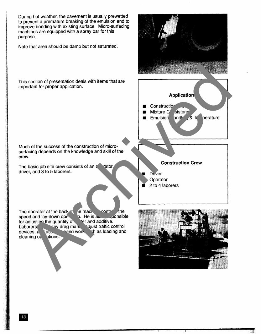
The operator at the back of the machine controls the speed and lay-down operation. He is also responsible for adjusting the quantity of water and additive. Laborers repair any drag marks, adjust traffic control devices, and assist in hand work such as loading and cleaning operations.
Application
Construction Crew Mixture Consistency Emulsion Handling & Temperature
Construction Crew
Driver Operator 2 to 4 laborers
Archive
d
Mixture Consistency
Stiff Mix Causes Early Setting Wet Mix Results in Segregation
Emulsion Handling and Temperature
Avoid Excessive Emulsion Pumping Avoid High Emulsion Temperatures
Construction Quality
Texturinglsealing Rut Filling Scratch Course
TexturinglSealing
Rippling Drag Marks Texture Uniformity Joints Edgelines
When the micro-surfacing is deposited in the spreader box, it should be of desirable stability and consistency. If the mix is too stiff, it may prematurely break/set in the spreader box. If it is too fluid, the mixture may segregate or run into channels. Slightly drier mixtures generally perform better than wetter mixtures.
Other items that will affect the mixture break time and therefore consistency are emulsion handling and application temperature. Excessive pumping of the emulsion may result in a lowering of emulsion viscosity or separation of ingredients. Hot emulsions may break too fast, resulting in streaks or drag marks. For best results, the emulsion temperature should be between 27 and 50 'C depending on the ambient conditions.
This part of the presentation will focus on several factors that can affect micro-surfacing applications for texturing and rut filling.
One of the most common uses of micro-surfacing is surface texturinglsealing. Micro-surfacing should result in a smooth, skid-resistant surface. To achieve this, the finished surface should be free from rippling and drag marks. In addition, the surface should have uniform texture and good quality joints and edgelines. Archive
d
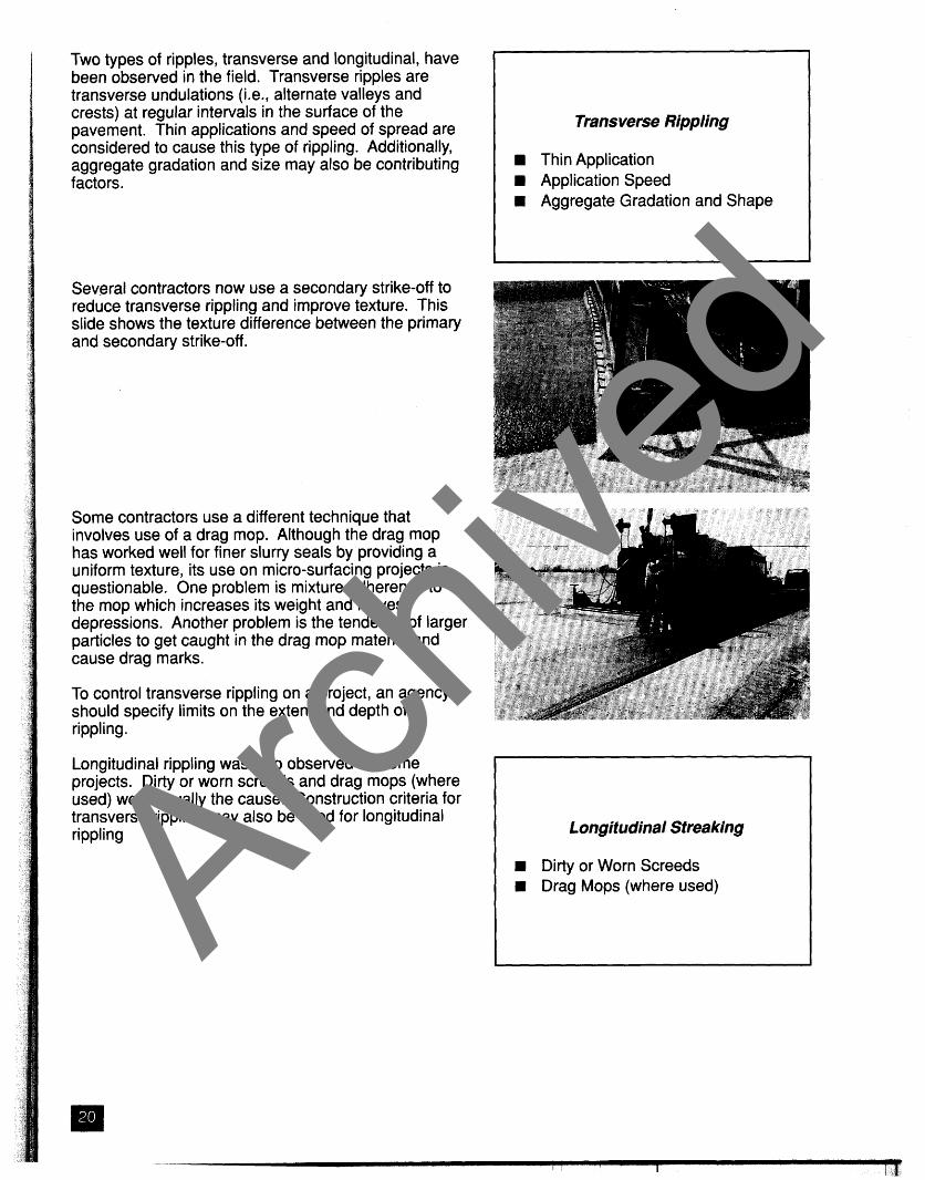
Two types of ripples, transverse and longitudinal, have been observed in the field. Transverse ripples are transverse undulations (i.e., alternate valleys and crests) at regular intervals in the surface of the pavement. Thin applications and speed of spread are considered to cause this type of rippling. Additionally, aggregate gradation and size may also be contributing factors.
Transverse Rippling
Thin Application Application Speed Aggregate Gradation and Shape
Several contractors now use a secondary strike-off to reduce transverse rippling and improve texture. This slide shows the texture difference between the primary and secondary strike-off.
Some contractors use a different technique that involves use of a drag mop. Although the drag mop has worked well for finer slurry seals by providing a uniform texture, its use on micro-surfacing projects is questionable. One problem is mixture adherence to the mop which increases its weight and leaves depressions. Another problem is the tendency of larger particles to get caught in the drag mop material and cause drag marks.
To control transverse rippling on a project, an agency should specify limits on the extent and depth of rippling.
Longitudinal rippling was also observed on some projects. Dirty or worn screeds and drag mops (where used) were usually the cause. Construction criteria for transverse rippling may also be used for longitudinal rippling I Longitudinal Streaking
Dirty or Worn Screeds Drag Mops (where used) Archive
d
Tear/Drag Marks
4 Existing Surface R Worn Screeds
lnsuff icient Material Premature Breaking Oversized Aggregates
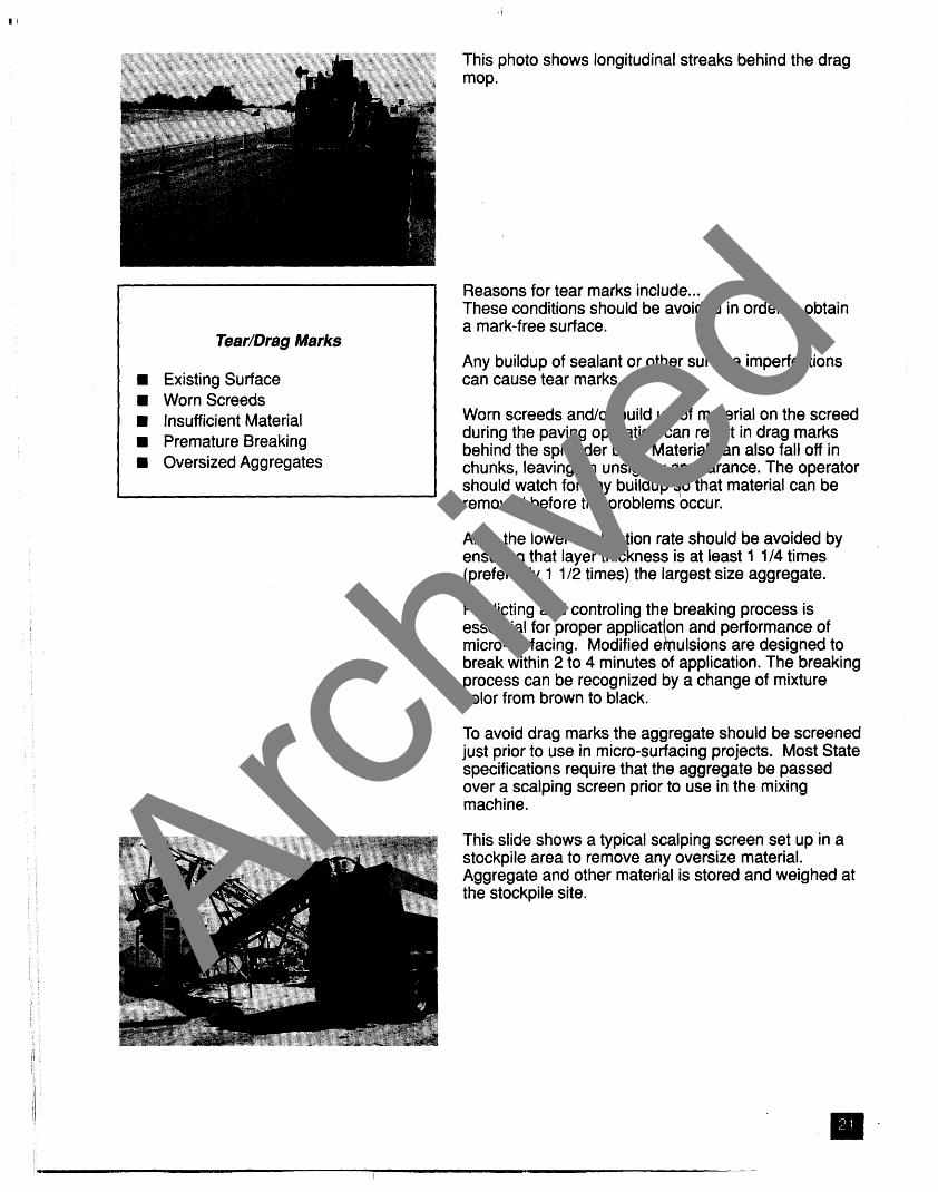
This photo shows longitudinal streaks behind the drag mop.
Reasons for tear marks include ... These conditions should be avoided in order to obtain a mark-free surface.
Any buildup of sealant or other surface imperfections can cause tear marks.
Worn screeds andlor build up of material on the screed during the paving operation can result in drag marks behind the spreader box. Material can also fall off in chunks, leaving an unsightly ppearance. The operator should watch for any builduplo that material can be removed before the problems occur.
Also, the lower application rate should be avoided by ensuring that layer thickness is at least I 1/4 times (preferably 1 112 times) the largest size aggregate.
Predicting and controling the breaking process is essential for proper applicat on and performance of micro-surfacing . Modified e I, ulsions are designed to break within 2 to 4 minutes of application. The breaking process can be recognized by a change of mixture color from brown to black.
To avoid drag marks the aggregate should be screened just prior to use in micro-surfacing projects. Most State specifications require that the aggregate be passed over a scalping screen prior to use in the mixing machine.
This slide shows a typical scalping screen set up in a stockpile area to remove any oversize material. Aggregate and other material is stored and weighed at the stockpile site. Archive
d

Several measures can be taken to obtain a uniform texture. These include ...
If a very dry mixture used it will break/set early and not bond well with the existing surface. This slide shows a project where debonding started within a few days of placement.
This slide shows a micro-surfacing project 30 to 45 minutes after application. This contrast in texture is usually caused by a wet mixture.
This is another example of a wet mixture. In this case excessively fluid mixture and/or improper material distribution are responsible for such inconsistency. The emulsions should be formulated to allow contractors to apply a relatively dry, consistent mix during all roadway conditions.
Also, the spreader box should be able to distribute the material evenly across its full width. The industry is considering design improvements to currently-used spreader boxes. One possible design improvement would replace spreader pedal augers with spiral-ribbed augers to improve distribution of mixture. Another method would segment the box with diversion chutes and gates (plates) to attain more uniform distribution of the mixture over its full width.
Texture Uniformity
Avoid a very Dry Mixture Avoid a Wet Mixture Use a Good Condition Spreader Box
Archive
d
Joints
Longitudinal Lateral
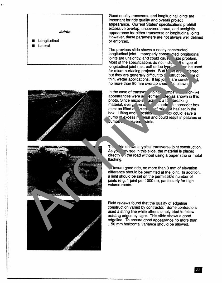
Good quality transverse and longitudinal joints are important for ride quality and overall project appearance. Current States' specifications prohibit excessive overlap, uncovered areas, and unsightly appearance for either transverse or longitudinal joints. However, these parameters are not always well defined or enforced.
The previous slide shows a neatly constructed longitudinal joint. Improperly constructed longitudinal joints are unsightly, and could cause a ride problem. Most of the specifications do not indicate the type of longitudinal joint (i.e., butt or lap type) that can be used for micro-surfacing projects. Butt joints are preferred but they are generally difficult to construct because of thin, wetter applications. If lap joints are constructed, no more than 80 mm overlap should be allowed.
In the case of transverse joints, humps and patch-like appearances were sometimes noted as shown in this photo. Since micro-surfacing is a fast-breaking material, every time a stop is made, the spreader box must be lifted and cleaned of mix that box. Lifting and repositioning the box hump of excess material and could bumps at transverse joints.
This slide shows a typical transverse joint construction. As you may see in this slide, the material is placed directly on the road without using a paper strip or metal flashing.
To insure good ride, no more than 3 mm of elevation difference should be permitted at the joint. In addition, a limit should be set on the permissible number of joints (e,g. 1 joint per 1000 m), particularly for high volume roads.
Field reviews found that the quality of edgeline construction varied by contractor. Some contractors used a string line while others simply tried to follow existing edges by sight. This slide shows a good edgeline. To ensure good appearance no more than f 50 mm horizontal variance should be allowed. Archive
d

Rut filling is another major use of micro-surfacing. Rut filling should result in smooth texture and corrected surface profile that should not rerut for several years.
Rut filling by micro-surfacing provides a longer service life if the existing pavement is stable and/or if the rut is caused by wear or mechanical compaction of the pavement structure.
Generally, if the pavement has been in service for 10 years and has developed only 15 to 25 mm deep ruts, the pavement could be considered stable. Wheel consolidations are generally limited to 5 to 15 mm in depth depending on the surface thickness.
Plastic flow in the surface layer may be recognized by dual wheel track ruts in each wheel path or by a depression near the center of the applied load with slight humps on either side of the depression. If desired cores can be taken to determine the cause of rutting within pavement structure.
This slide shows a pavement with plastic flow. For this type of pavement, the micro-surfacing will correct the surface profile for only a short period depending on the cause and severity of the rut. If micro-surfacing has to be used as a temporary measure, any elevated deformations present due to plastic flow should be milled prior to rut filling.
This slide shows a one-year-old micro-surfacing project constructed to repair unstable pavement.
Rut Filling
Corrected Profile UniformTexture
Plastic Flow
Observation Coring
Archive
d

Filling Deep Ruts
w Use Thinner lift (max. 38 mm deep) w Use Coarser Aggregate
Allow 24 hours between two Layers
Several States have experienced instances of bleeding when filling ruts of 40 mm or more in a single pass. The coarser aggregate fraction can settle into the deeper rut areas, leaving binder-rich fines at the surface and resulting in a low or uneven surface texture and the unsightly appearance of "fatty spots."
For best results, deep ruts over 25 mm should be filled in multiple passes. Using a coarse$ aggregate and a dryer mix will also help alleviate flushing problems when filling deeper ruts. Normally, this situation is infrequent as most States require remedial measures once rut depths exceed 13 mm. A sufficient curing period (24 hours under traffic) should be provided between placement of successive layers.
At the end of construction, the transverse profile must not show any depressions. A straight edge may be used for this purpose. This slide shows one of the projects where ruts were not completely filled.
Leveling Course (Scratch Course)
Surface Uneven Ruts Less Than 5 mm
In instances where the surface is uneven or where depth of wheel ruts is between 5 and 15 mm, two layers of micro-surfacing may be used. The first application could be used as a scratch course to reestablish the transverse profile, followed by a surface course. If micro-surfacing surface course is applied directly over an uneven pavement, the resulting surface may also be nonuniform. If the ruts are more than 15 mm (preferably 10 mm), the ruts must be filled with a rut box prior to applying any final course. If the standard paving box is used for filling deeper ruts, flushing can occur in wheel paths.
The scratch course is placed by a full-width spreader box with steel strike-off. During application the screed is set to make contact with high points on the pavement surface, thereby filling the low points. Cautions described for texturing course are also applicable to scratch course application. Archive
d

This slide shows a completed scratch course application. The pass width is normally set at 3 m to avoid application over painted lane lines.
This section of presentation includes recommendations for certain uses such as ...
Micro-su rfacing use directly on paving fabrics has not proven effective. Incidences of raveling within a few months have been reported.
Recommendations on Other Uses
Over Fabrics Over Oxidized and Uneven Surfaces
H Over PCC Pavements Over OGFC andlor Raveled Surfaces
H Over Flushed Surfaces Over Paint Striping
If the surface appears too oxidized or uneven, it may be desirable to place a leveling course of micro- surfacing or hot mix asphalt (HMA). Alternatively, milling or heater scarification may be used to address oxidation and correct surface unevenness.
Micro-surfacing applied directly over the PCC pavement may start to debond within a relatively short period. To ensure a proper bond with existing PCC surface, a tack coat (0.22 to 0.45 l/m2) should precede the application of micro-surfacing. Arch
ived

If the surface is porous (e.g., OGFC), it should be treated with a diluted emulsion spray or thin, wet micro- surfacing mixture to seal the surface prior to application of a texturing course. Stripping could occur if underlying pavement is not sealed.
Reviews in several States indicate that micro-surfacing placed over thermoplastic material will ravel off the marking. Accordingly, thermoplastic and cold plastic marking (and preferably paint marking) should be scarified or removed prior to micro-surfacing application.
Paint marking can be placed over micro-surfacing the next day. However, thermoplastic marking should not be applied until micro-surfacing completely cures, which may take 7-1 4 days.
Micro-surfacing has been used by some States to correct/minimize flushing on chip seals and asphalt concrete pavements. Micro-surfacing use on flushed pavements should be limited to sites where flushing is low to moderate, otherwise flushing may reappear.
When used on flushed pavements, two applications of micro-surfacing may be considered. The first application may consist of considerably reduced binder content and the second of a slightly reduced to normal binder content.
Current Specifications Set requirements for Aggregate & Emulsion No Requirements for Water, Mineral Filler, and Additive Few States Set Requirements for Mixture Design Equipment & Construction Specifications are rather Loose
w Quality Control is Normally left up to Contractor
Although current State specifications set requirements for design and construction, several improvements can be made to these specifications.
As far as mixture design is concerned, State specifications set requirements for two of the 4
component materials, aggregate and emulsion. However, no requirements are set for other materials, such as water, mineral filler, and additive. While amount of mineral filler is generally controlled by gradation. Amount and usage of water and additive are left up to the contractor. Archive
d

Only a few States specify any requirements for mixture design itself. Where specified, the tests follow either ISSA guidelines for micro-surfacing or Marshall test procedures for hot mix asphalt. Construction specifications address types of equipment and placement operation in general terms. Quality control is usually left up to the contractor and representatives from the mixture design laboratory or the emulsion supplier. The success of micro- surfacing application and eventual performance is, therefore, affected by the experience level of the contractor.
Materials control by the State is usually limited to sampling and testing of the aggregate and the mixture to ensure conformance with the specikation. Extraction tests are run on the mixture samples to check the percentage of asphalt cement and aggregate.
Attainment of a quality product and long-term performance is dependent on the quality of the materials, design, and construction. Since current specifications require high-quality materials, it leaves the mixture design and construction areas where most of the improvements can be affected. While improvement in the design area will take a larger, coordinated effort and some time, improvement in the construction area can be affected immediately.
One way to ensure a quality product is to strengthen existing construction criteria through use of end result specifications. End result specifications cover those items that can be identified and are present at the end of construction. These items generally do not change over time and may include ...
Another approach to ensure a quality product and long- term performance is the use of warranty specifications. A warranty clause will typically include items covered under both end result and performance specifications.
Quality Product
H Quality Materials Good Mixture Design
H Quality Construction
End Result Specifications
Finished Surface Longitudinal & Transverse Joints Edges Time to Traffic
H Cross-section H Surface Friction
Warranty Specifications
H End Result Specification H Performance Specification
Archive
d

Performance Items
Flushing Ravelingldebonding Surface Friction Rutting Noise Levels
End result specifications were discussed previously. Performance specifications address items that can change over time and may include ...
A sample guide warranty specification is included in your hand out. This specification was developed by a joint FHWA, State, Industry technical working group. This warranty specifications is planned to be field tested in several States under FHWA Experimental Project No. 14.
Criteria in this sample specification or those discussed previously in this presentation should not be construed as recommended values, but rather as guidelines. Each State highway agency is encouraged to develop its own end result criteria that are appropriate for the variables encountered in that State. When developing criteria, it is important that all requirements be enforceable.
Requirements that are difficult to enforce should not be used because compliance cannot be measured in the field. To verify the applicability of the specifications, the agency should develop an experimental work plan to determine which requirements are enforceable.
Archive
d
Performance of micro-surfacing depends on many factors such as climatic conditions, traffic volumes, existing pavement conditions, quality of materials, mixture design, and construction quality. Micro- surfacing performance is summarized in the State-of- the-Practice paper. (See handout.)
When properly designed and constructed, micro- surfacing provides 4 to 7 years of service life for its two major uses, filling of wheel ruts and providing a texturing layer. Micro-surfacing has also been used to address distresses, such as raveling, flushing, and crack filling. Performance results for these applications have been mixed but are generally encouraging.
PERFORMANCE
Climatic Conditions Traffic Volumes Existing Pavement Conditions Quality of Mixture Design & Material Quality of Construction
PERFORMANCE FINDINGS
w TexturingISkid Resistance w Rut Filling
Crack Filling w Improve Raveled Surfaces
Improve Flushed Surfaces
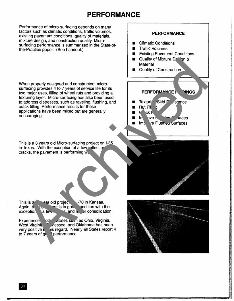
This is an 8 year old project on 1-70 in Kansas. Again, this pavement is in good condition with the exception of a few cracks, and minor consolidation.
Experience of other States such as Ohio, Virginia, West Virginia, Tennessee, and Oklahoma has been very positive in this regard. Nearly all States report 4 to 7 years of good performance. Arch
ived
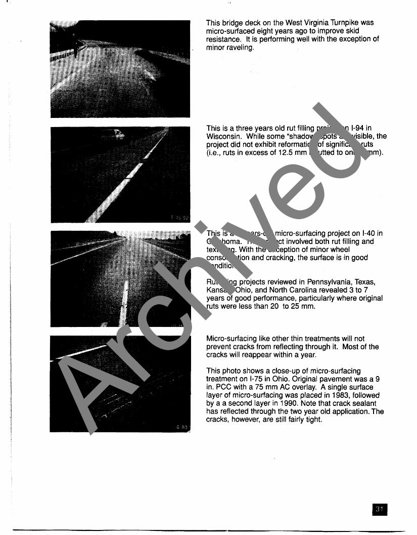
This bridge deck on the West Virginia Turnpike was micro-surfaced eight years ago to improve skid resistance. It is performing well with the exception of minor raveling.
This is a three years old rut filling project on 1-94 in Wisconsin. While some "shadow" spots are visible, the project did not exhibit reformation of significant ruts (i.e., ruts in excess of 12.5 mm rerutted to only 5mm).
This is a 5-years-old micro-surfacing project on 1-40 in Oklahoma. This project involved both rut filling and texturing. With the exception of minor wheel consolidation and cracking, the surface is in good condition.
Rut filling projects reviewed in Pennsylvania, Texas, Kansas, Ohio, and North Carolina revealed 3 to 7 years of good performance, particularly where original ruts were less than 20 to 25 mm.
Micro-surfacing like other thin treatments will not prevent cracks from reflecting through it. Most of the cracks will reappear within a year.
This photo shows a close-up of micro-surfacing treatment on 1-75 in Ohio. Original pavement was a 9 in. PCC with a 75 mm AC overlay. A single surface layer of micro-surfacing was placed in 1983, followed by a a second layer in 1990. Note that crack sealant has reflected through the two year old application. The cracks, however, are still fairly tight. Archive
d

This photo shows another micro-surfacing project on a moderate volume road in Ohio. Difference in the treated and nontreated areas are evident in this photo.
Micro-surfacing has been used to repair OGFCs and raveled surfaces with considerable sucess. This slide shows a 3 years old micro-surfacing project placed on top of a raveled OGFC project in Oklahoma
Archive
d

COSTS
COST FACTORS
Availability of Materials Availability of Contractors Size of the Project Application Rates Maintenance of Traffic Number of other Bid Items
Unit Cost of Micro-Surfacing
State Cost ($/Ma) NC 100-1 10 PA 1 25-1 50 VA 100-110 TX 90-95 OK 90-95
Measurement Methods
Area Basis Material Basis
Micro-surfacing costs vary depending on many factors, including location, availability of materials and contractors, application rates, maintenance of traffic, and other bid items. The number and size of projects in each State also affect the application cost in that State.
Micro-surfacing is approximately two to three times the cost of hot mix asphalt concrete on a weight basis. Since its unit cost is higher, the cost-effectiveness of micro-surfacing depends on the use of thinner applications.
This slide shows unit cost of micro-surfacing in many States. These costs pertain to rural areas and includes only micro-surfacing placement and maintenance of traffic costs.
Currently, several methods are used for measurement and payment of micro-surfacing.
Measurement methods include (1) measurement of quantity of aggregate and polymer-modified emulsion, (2) measurement of quantity of composite mixture, and (3) measurement of surface area. Payment is made under either contract unit price of component materials and composite mixture, or contract unit price per square yard. Table 4 (in your handout) gives measurement methods and basis of payment for micro- surfacing projects in several States.
Archive
d
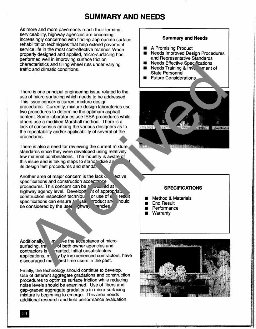
SUMMARY AND NEEDS As more and more pavements reach their terminal serviceability, highway agencies are becoming increasingly concerned with finding appropriate surface rehabilitation techniques that help extend pavement service life in the most cost-effective manner. When properly designed and applied, micro-surfacing has performed well in improving surface friction characteristics and filling wheel ruts under varying traffic and climatic conditions.
There is one principal engineering issue related to the use of micro-surfacing which needs to be addressed. This issue concerns current mixture design procedures. Currently, mixture design laboratories use two procedures to determine the optimum asphalt content. Some laboratories use ISSA procedures while others use a modified Marshall method. There is a lack of consensus among the various designers as to the repeatability andlor applicability of several of the procedures.
There is also a need for reviewing the current mixture standards since they were developed using relatively few material combinations. The industry is aware of this issue and is taking steps to standardize and adjust its design test procedures and standards.
Another area of major concern is the lack of effective specifications and construction acceptance procedures. This concern can be addressed at the highway agency level. Development of appropriate construction inspection techniques or use of end result specifications can ensure a quality product and should be considered by the user highway agencies.
Additionally, to improve the acceptance of micro- surfacing, training of both owner agencies and contractors is warranted. I nitial unsatisfactory applications, mostly by inexperienced contractors, have discouraged many first time users in the past.
Finally, the technology should continue to develop. Use of different aggregate gradations and construction procedures to optimize surface friction while reducing noise levels should be examined. Use of fibers and gap-graded aggregate gradations in micro-surfacing mixture is beginning to emerge. This area needs
Summary and Needs
A Promising Product Needs Improved Design Procedures and Representative Standards
w Needs Effective Specifications Needs Training & Involvement of State Personnel
w Future Considerations
SPECIFICATIONS
Method & Materials W End Result
Performance W Warranty
additional research-and field performance evaluation.
Archive
d
FUTURE DEVELOPMENT
Materials Design Equipment & Construction
Archive
d

Archive
d

Archive
d

Archive
d

Archive
d

Archive
d