Embed Size (px)
Citation preview

DESIGN, CONSTRUCTION, AND EVALUATION OF A
FUEL TANK/TOOL BOX COMBINATION
by
Michael R Chase Jr.
BioResource and Agricultural Engineering
BioResource and Agricultural Engineering Department
California Polytechnic State University
San Luis Obispo
2009

ii
TITLE : Design, Construction, and Evaluation of a Fuel Tank/Tool Box Combination
AUTHOR : Michael R. Chase Jr. DATE SUBMITTED : December 1, 2009 Mark A. Zohns Senior Project Advisor Signature Date Richard A. Cavaletto Department Head Signature Date

iii
ACKNOWLEDGEMENTS
First, I would like to start by thanking my parents for all their help and support throughout my life. Without out them I would have had the opportunity to even attend Cal Poly. Second, I would like to thank my advisor, Dr. Mark A. Zohns, for his support and guidance throughout this project and over my time at Cal Poly. Third, I would like to thank Nick Darr for his help and for being my lab partner for many weekends, so I could continue my work on this project.

iv
ABSTRACT This project is the design and development of a combination tool box and auxiliary fuel tank built as a single unit, specifically built for a 2000 Ford F250 short bed truck; having a fuel capacity exceeding 50 gallons; meeting federal requirements for motor vehicle fuel tanks; performing as an auxiliary tank using the factory fuel gauge and having a tool box that can carry a wide array of tools. This paper will describe the design considerations, the regulation requirements, the material selection, and the construction process of the combination tool box/fuel tank.

v
DISCLAIMER STATEMENT
The university makes it clear that the information forwarded herewith is a project resulting from a class assignment and has been graded and accepted only as a Fulfillment of a course requirement. Acceptance by the university does not imply technical accuracy or reliability. Any use of the information in this report is made by the user(s) at his/her own risk, which may include catastrophic failure of the device or infringement of patent or copyright laws. Therefore, the recipient and/or user of the information contained in this report agrees to indemnify, defend and save harmless the State its officers, agents and employees from any and all claims and losses accruing or resulting to any person, firm, or corporation who may be injured or damaged as a result of the use of this report.

vi
TABLE OF CONTENTS
SIGNATURE PAGE...................................................................................................... ii ACKNOWLEDGEMENTS............................................................................................. iii ABSTRACT.................................................................................................................. iv DISCLAIMER STATEMENT.......................................................................................... v LIST OF FIGURES........................................................................................................ vii LIST OF TABLES.......................................................................................................... viii INTRODUCTION......................................................................................................... 1 Background……….…………………………………………………………………………………….. 1
Justification…………………................................................................................ 2
Objectives………………….................................................................................. 2 LITERATURE REVIEW................................................................................................. 3 PROCEDURES AND METHODS................................................................................... 5
Design Procedure.......................................................................................... 5
Construction Procedure................................................................................ 7
Measurement Procedure.............................................................................. 14
Testing Procedure......................................................................................... 15
Evaluation Procedure…................................................................................. 15
Cost Analysis………………................................................................................. 16

vii
Laws, Regulations, and Standards................................................................. 16 RESULTS.................................................................................................................... 18 DISCUSSION.............................................................................................................. 19
Construction Technique…….......................................................................... 19
Design Changes……………………………………………………………………………………….. 19 RECOMMENDATIONS............................................................................................... 23 REFERENCES.............................................................................................................. 24 APPENDICES
Appendix A: How Project Meets Requirements for the BRAE Major...........................................................................
25 Appendix B: Design
Calculations............................................................... 28 Appendix C: Construction
Drawings.......................................................... 30
LIST OF FIGURES
1. American Tank and Toolbox Fuel Tank…….……………………………………………….. 3
2. Transfer Flow Fuel Tank……………………………………………………………………………. 3
3. Transfer Flow Tank with Installation Items………………………………………………. 4

viii
4. SolidWorks Model of Project Design ………………………….….………………………… 5
5. Underside View of SolidWorks Model………………………………………………………. 6
6. CNC Layout for Plasma Cutter……………………….…………………………………………. 8
7. TIG Welding Inside of Project……………………………………………………………………. 8
8. Many degree bends of the Project……………………………………………………………. 9
9. Fitting the Shell to the Bed of the Truck……………………………………………………. 9
10. Exact Fit of the Project to the Bed of the Truck..………………………………………. 9
11. Project being Tacked Together..……………………………………………………………….. 10
12. Tacks and Checking the Straightness of the Edge……………………….…………….. 10
13. Baffle Plate in Place………………………….………………………………………………………. 11
14. Support Structure Under Separation Plate……………..………………………………… 11
15. Drain Bung Welded into place………………………………………………………………….. 12
16. Fuel Fill Box and Coupler being Constructed…………………………………………….. 12
17. Fuel Fill Box and Coupler Welded into Tank.…………………………………………….. 12
18. Frame of Lid……………………………………………….…………………………………………….. 13
19. Full Constructed Lid.………………………………….…………………………………………….. 13
20. Finished Product….…………………………………….…………………………………………….. 14
21. SolidWorks Model of Fuel Area………………….…………………………………………….. 14
22. Volume of Toolbox Area………………….……………………………………………………….. 18

ix
23. TIG Welding on the Project.…………….……………………………………………………….. 19
24. Clearance Issues on Lid……..…………….……………………………………………………….. 20
25. Fill Port Welding Issues……..…………….……………………………………………………….. 21
26. Trying a different Technique to Weld……………………………………………………….. 21
27. Drain Port View………….……..…………….……………………………………………………….. 22
28. Project in Bed of Ford Truck…………….……………………………………………………….. 23
LIST OF TABLES
1. Sum of Total Cost……………………………………………………………………………………… 16

1
INTRODUCTION
Background
For those who drive trucks, there are options for tool boxes or supplemental/auxiliary fuel tanks to put into the bed of the truck. Tool boxes are great in that they allow the driver to carry tools or other items that might need to be locked up and kept safe without carrying these items in the cab of the truck. In the cab of the truck the tools can take up space and can be dangerous airborne objects in the event of an accident. Supplemental/auxiliary fuel tanks allow for longer distances between fill-ups. This is important with trucks especially when hauling trailers on long trips. While towing, the fuel mileage of any vehicle is decreased, so having additional fuel on board is helpful; as well as having fuel available in remote locations. With the extra fuel capacity the driver can also choose the cheaper fuel stations to fuel up at. There are units available that have combined the supplemental/auxiliary fuel tank and tool box into one. A problem with these units is the limited amount of fuel capacity. They usually have a 50 gallon maximum capacity; because they are meant to be a “one size fits all” application. Another problem with these units is the refueling process. The majority of these type units are designed to have a 12 volt pump to transfer the fuel to the main fuel tank. This usually requires the driver to stop, put a nozzle from the supplemental tank into the main tank, and manually fill the main tank. There are other units that tap into the fill neck of the main tank and fill the tank while moving, but the problem with this type of unit is the driver needs to remember to turn off the transfer pump before the main tank overflows, wasting fuel and creating an environmental hazard. A supplemental tank is more of a supply tank. Usually a supplemental tank is equipped with a pump and nozzle that will transfer the fuel, either to the vehicle it is placed in or to another vehicle or tractor that might be in need fuel. This is different from an auxiliary tank that is more of a secondary or back-up tank for the vehicle it is placed in. Auxiliary tanks can be activated from inside the cab of the vehicle so that the driver does not have to stop to refuel the vehicle. This senior project looked at the good points and the bad points of having a combination tool box and fuel tank unit to put into the bed of a truck. Keeping the good points and improving upon the bad points to make a unit that has better fuel capacity, is designed as an auxiliary tank rather than a supplemental tank, and still provides a tool box large enough to

2
hold a full set of tools. The truck will be modified with a switch to change from the main tank to the auxiliary tank, and it will also allow the factory fuel gauge to work with both tanks. Justification
A short bed truck is the basis of this project and as with most short bed trucks, the main fuel tank is smaller than what would be found in a long bed truck. The truck has a maximum capacity of 25 gallons which limits the range from around 250 to 500 miles depending upon what is being towed or hauled. On long trips when pulling a trailer, there may also be long distances between fueling stations. It can be very costly and time consuming to run out of fuel on these long stretches. Not only is there the wait on the tow truck, but the cost to move the vehicle to a location it can be refueled or for the tow truck to bring enough fuel to drive the vehicle to a fuel station can be expensive. Another item to watch for is the large price differences between fueling stations. With having the additional capacity a driver can find stations where the price is cheaper for comparable fuels. The project was not meant to be confined to a “one size fits all” application, like can be found from most companies. When one compares bed sizes from one brand to another, all trucks are not created equal. When comparing the bed size of the project truck to the bed of another brand truck, the project truck was found to be about 3” larger in all directions; front to back, side to side, up and down, bed rail to top of cab. So there is quite a bit more space that can be used, that a “one size fits all” application will not take advantage of. Objectives
It was necessary to increase the fuel capacity beyond the 50 gallons offered with units currently marketed, but did not want to make the unit over 119 gallons to where it required placards for the fuel capacity. This project was also designed to retain usable bed space with the truck and preserve the use of the gooseneck hitch that is currently installed in the bed of the truck. The design of the project encompassed a fuel tank that worked as an auxiliary fuel tank rather than a supplemental tank. This was to be sure that the driver did not have to stop for refueling or worry about forgetting to stop the filling of the main tank from the supplemental tank. This way

3
the driver has fewer worries on his/her mind and can keep his/her mind to the road to be a safer driver. In designing the project the tank is to be filled in a timely manner, so the fill ports need to be large for a truck-stop nozzle, which is 2” O.D. Another item that was to be taken advantage of at a truck stop was the ability to fill the tank from both sides of the vehicle. By designing for this feature it also give the driver the ability to fuel both the auxiliary tank and the main fuel tank at the same time.
LITERATURE REVIEW
A search was conducted for several reasons. The first was initiated to determine the rules and regulations of hauling diesel fuel. Another search determined what combination fuel tank/tool boxes were currently available on the market. The last looked at the construction materials available.
Figure 1. American Tank and Toolbox Fuel Tank.
Transfer Flow, Inc. of Chico, CA is a large manufacture of all types of transfer tanks and auxiliary tanks. They also produce many combination tanks for all types of vehicles. “Transfer Flow is a technically oriented manufacturing company, which is equipped and staffed to handle complete fuel system requirements” (Transfer Flow Inc, 2009). They have been building tanks for 25 years and have all the rules and regulations needed for having an auxiliary tank. Their tanks are built to meet FMVSS 301 (Federal Motor Vehicle Safety Standards), which stated that anyone who alters a vehicle must meet or exceed the structural integrity and performance of the OEM (Original Equipment Manufacturer) fuel system (Transfer Flow Inc, 2009). Federal Motor Vehicle Safety Standards 301 states that its purpose is to reduce the deaths and injuries that can result from any fuel that might spill during and after vehicle accidents (US Dept. of Transportation, 1999).

4
Figure 2. Transfer Flow Fuel Tank.
The Federal Motor Carrier Safety Administration also has rules and regulations for liquid fuel tanks. Part 393.67 pertains to tanks that contain or supply fuel for the operation of commercial motor vehicles. It also applies to “auxiliary equipment installed on, or used in conjunction with commercial motor vehicles” (US Dept. of Transportation, 2005). This part contains many rules and regulations that apply very closely to what a fuel tank should conform too. It covers a lot of area that many manufacturers might not think about when designing and building a fuel tank. One such item would be the placement of the supply line on the fuel tank. The easiest position would be at the bottom of the tank so it will just gravity feed into the system. This is a problem because in the case of an accident, if the line feeding from the tank into the fuel system of the vehicle is damaged; fuel will leak into the environment. These rules will help safe guard a fuel tank from becoming a major hazard.
Figure 3. Transfer Flow Tank with Installation Items.
Another set of federal rules to be aware of when hauling fuel is the Hazardous Materials Regulations. Technically under these regulations diesel is considered to be a combustible liquid. It states that “A flammable liquid with a flash point at or above 38 °C (100 °F) that does not meet the definition of any other hazard class may be reclassified as a

5
combustible liquid” (GPO Access 173.150, 2009). These regulations also allow a container that is permanently secured, protected from damage in the event of an accident or turnover, and built, with non-specific metal, for petroleum products, having a capacity of less than 119 gallons may be used by an interstate motor vehicle (GPO Access 173.8, 2009).
In looking at materials, other transfer tank manufactures were using a variety of materials, and also different gauges depending on the material that was used for that particular metal. Some companies used aluminized steel, which helps to prevent rust from forming, but does not stop it completely (American Tank and ToolBox, 2005). Most manufacturers use aluminum in the construction of fuel tanks. When using steel or aluminized steel most companies went with a 14 gauge sheet (Northern Tool and Equipment, 2009). The same companies when using aluminum had a 10 gauge or 1/8th inch sheet.
PROCEDURE AND METHODS
Design Procedure
Overall Design . This senior project was meant to follow some of the same designs of the older toolboxes that came up and over the edge of the bedrails, usually about 6” or higher above them. The rational for this design was to give more room for capacity in both the tool box section and in the fuel tank. The research found there is no company that offers this as a standard configuration. This project also wanted to make certain that the unit fit the vehicle and maximized the available space, so the bed of the truck was measured at the front, near the cab, where the unit will be placed, and the fuel tank/tool box was fitted to the exact shape of the bed.

6
Figure 4. SolidWorks Model of Project Design. The maximum gallons that could legally be carried without placards, 119 gallons, was taken into consideration as well as the amount of room needed for a tool box to handle a wide variety of tools that could be carried. All the dimensions were looked at very carefully to ensure that the box would not obstruct the view through the back window. The process of filling the tank needs to be smooth and fast. Filling a large tank can take a while, so the next design feature came from the experience of running from truck-stop to truck-stop, where for each pump they have two nozzles, one on each side of the truck. Most of the time this is for the big rig drivers to fill both tanks on the truck at once, so this would work well for this project to. The box was not going to be confined to filling on one side or the other so it was designed to be filled from both sides.
Figure 5. Underside View of SolidWorks Model.
The fill necks on the tank were designed at an angle so that when the tank is filled the port will be above the fuel level. The automatic stop on the fuel nozzle will shut the flow off before it reaches the top. The Baffle plate inside was designed to help with the fuel sloshing around, when cornering. It also is designed to help support the separation plate. It leaves about 2” underneath for the fuel to equalize and keep from limiting the flow. Equipment Selection . Several options were looked in to when determining what to build the box out of. The three options were Carbon Steel, Stainless Steel, and Aluminum.
7
The pros of using Carbon Steel are that it would have been the easiest to manufacture and cheapest to build. The con issue with Carbon Steel is corrosion. The Author’s personal experience has shown that numerous filters can become clogged with rust as a result of using carbon steel. Stainless Steel is better when it comes to corrosion issues, so this was another option that was looked at. The down side with Stainless Steel is that it is much harder to work with when constructing (welding and warping issues) and is more expensive to use. Relative cost per pound of stainless steel is $1.15, carbon steel is $0.15, and aluminum is $0.88. Aluminum was the last option considered on this project. The pros with aluminum are that it is corrosion resistant, easier to work with than Stainless Steel, and less expensive than Stainless Steel. It is also going to be the lightest material so that if this box ever does need to be moved a forklift would not be needed to remove the box from the bed of the truck. Aluminum weighs about 170 lb/ft3; steel and stainless steel both weigh about 500 lb/ft3. The cons with aluminum are the cost, the fatigue limits, and the workability of the material. The cost of the aluminum is still more expensive and more difficult to work with than Carbon Steel. Aluminum is another material to be careful with while welding, as it is easy to burn through and easy to warp the material. The fatigue limit is the range of cyclic stress, stress applied on and off in a cycling pattern, that can be applied to material without causing failure of the material. Ferrous alloys, steel and stainless steel, have a distinct limit to which no amount of cycles will cause failure. Aluminum on the other hand does not have a limit and eventually any cyclic loading will cause failure. In weighing the options Aluminum was the chosen material. Aluminum is going to give the best results with minimal problems. Sample Structural Calculation, please refer to Appendix B. Another item that had to be chosen was the locking, handle latches used to keep the toolbox locked. Many options of latches and locks are available for tool boxes, and all were considered for use with this project. The one that was thought to be the best and safest way to keep the toolbox secured was the locking, T-Handle latches. They will make it difficult in that both of the latches have to be turned to open the lid of the box, which, in turn, makes it safer if one lock is forgotten, the other one will not allow the box to be opened. Construction Procedure

8
Tools . A wide variety of tools and machines were used in the build of this project. Large sheets of aluminum were cut into the shapes needed. To cut the aluminum two different plasma cutters were used, a computer controlled unit and a handheld unit. The computer controlled unit made very nice long cuts. This machine was used to make some of the very large pieces needed. The handheld unit was used to make some inside cuts and smaller pieces. A shear was also used for some of the smaller pieces that were used as supports for larger pieces.
Figure 6. CNC Layout for Plasma Cutter.
Another machine used on this project was a Gas Tungsten Arc Welder (GTAW) also known as Tungsten Inert Gas Welder or TIG Welder. This was used to do all the welding on this project.
Figure 7. TIG Welding Inside of Project.

9
The largest machine used for this project was the 100 Ton Hydraulic Brake Press. This was used to make the bends of all degrees needed in the design of this project.
Figure 8. Many degree bends of the Project.
Other tools used include grinders, files, C-clamps, and hammers. These were used for mistakes, fine adjustments, or just cleaning up the look of the box. Construction . The construction of this project started with buying several sheets of aluminum to cut into the shapes needed. After making all cuts needed with either the plasma machines or the shear, the next step was to begin bending any pieces that needed bent. The largest sheet was the sheet that formed the bottom and the sides. There were several bends to be made to shape it to the bed of the truck.
Figure 9. Fitting the shell to the bed of the Truck.

10
Figure 10. Exact fit of the Project to the bed of the Truck.
After testing the fit of the large sheet, it was time to start the attachment of the
front and back of the project. Each piece was carefully placed and then
tacked to the large sheet.
Figure 11. Project being Tacked Together.
Figure 12. Tacks and Checking the Straightness of the Edge.
The next step was to put the baffle plate into place to add support to the front
and rear plate before completely welding them into place.
11
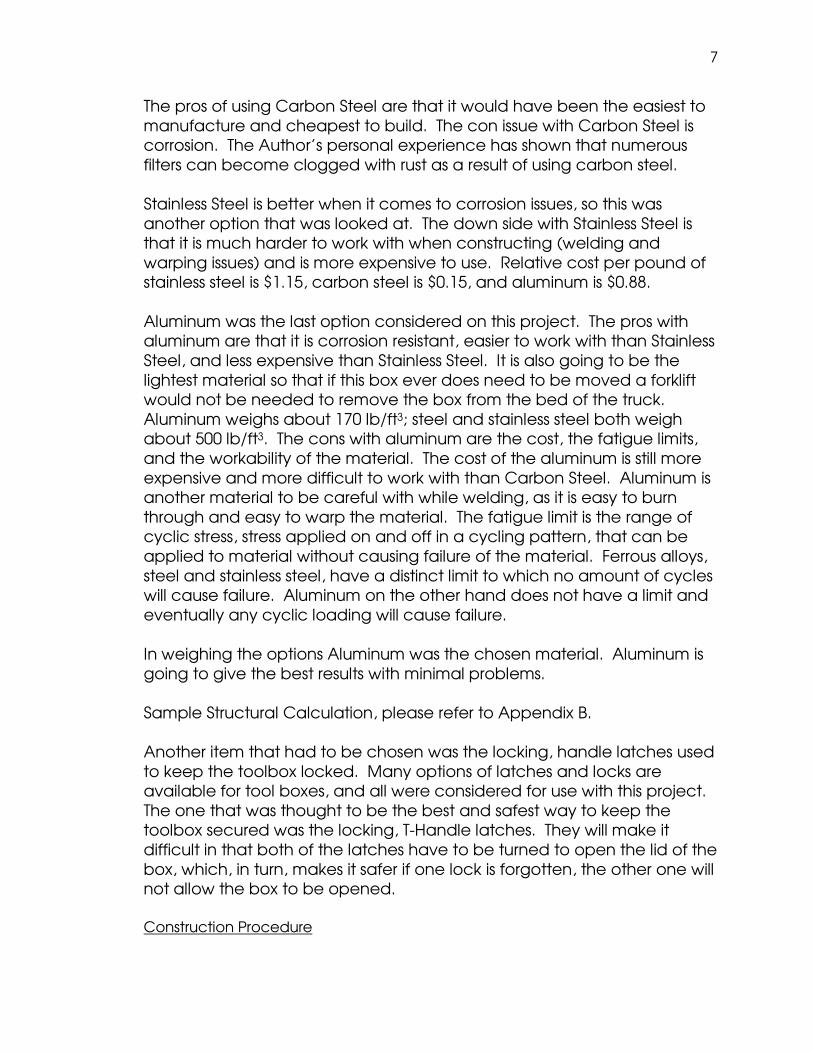
Figure 13. Baffle Plate in Place.
The baffle plate also works as a support for the separation plate when that is put
into place.
Next the rest of the support system was welded into place. This will support the
rest of the separation plate to keep it from deflecting from the weight of the tools
or other items in the tool area.
Figure 14. Support Structure Under Separation Plate.
After the support system was all welded into place the rest of the box was then
welded together. First the outside of the box was welded all the way around.
Next the inside of the box was welded. This was to double the weld and to keep
the tank from leaking as much as possible. This will lessen the chance of leak
because it will close both sides of the gap between the plates.

12
The next area that was worked on next was the drain plugs. First the holes were
drilled out so that the bungs fit. Then the bungs were put in place and welded
in.
Figure 15. Drain Bung Welded into place.
Then the fuel fill ports were built and put into place. This process started with
boxing in the fuel port area to keep the fuel fill above the tank level. A Coupler
was then welded to a plate. This coupler will allow the fuel caps to be attached
at a later time.
Figure 16. Fuel Fill Box and Coupler being Constructed.

13
Figure 17. Fuel Fill Box and Coupler Welded into Tank.
The Frame of the lid was the next section constructed. Using angle-bar
aluminum pieces and T-bar aluminum pieces a frame was welded together.
Then another sheet of aluminum was cut and bent to fit over the frame to add
strength and support to the lid.
Figure 18. Frame of Lid.
Figure 19. Full Constructed Lid.

14
The fuel supply line and fuel return to attach to the fuel system of the vehicle
were then setup up on the tank. A 3/8 inch aluminum tube was used. It was cut
at a 45 degree angle on the end of the tube. This angle opens the surface area
of the supply line which lowers the entrance losses. The tube was bent at a 90
degree to exit on the driver’s side of the tank, where the existing fuel system on
the truck is located; making access easier to connect the systems together.
After the fuel lines were in place the separation plate was placed on the
supports and welded into place. Holes were drilled in the plate at the three
crosses in the supports so that the plate could be welded in the middle, to try to
keep the plate from warping and also rattling later down the road.
Welding the hinge to the lid and then to the box was one of the last items. The
hinge already had holes so it was spot welded using the holes on both the tank
and the lid. After the lid was attached the gas shocks and locks were added on;
now the project was able to lift automatically and could be locked when
closed.
Figure 20. Finished Project.
Measurement Procedure
In designing the project the capacity the fuel tank was going to have needed to be measured. To measure the volume that would be available, geometry and trigonometry were used as some of the edges had variable angles. After finishing the calculations the capacity of the fuel tank was determined to hold about 80 usable gallons. SolidWorks was also used to check the volume of the tank.

15
Figure 21. SolidWorks Model of Fuel Area.
SolidWorks has a feature called Mass Properties that will determine the volume of any solid model. This model had a volume of 19299.61 cubic inches. (19299.61 cu in) / (1728 cubic inches/cubic feet) = 11.1688 cubic feet 11.1688 cu ft x 7.48 gallons/cu ft = 83.54 Gallons Also used was a tape measure to make any measurements of the area of the bed that the project would be placed. Testing Procedure
There are several tests that need to be done when working on a fuel tank. After the tank is finished, it needs to be checked for any leaks. Once the welding on the project was finished and the drain ports were installed, the plugs were threaded into the drain port and a hydrostatic test with water was ran to see if any leaks were found. Water was used for this test because the complete build of the box was not yet finished and no flammable liquid should be present in the box while welding. Water will evaporate and dry leaving nothing to worry about with any open flames. The next test was conducted after the fuel tank area was completed. For this an air valve was installed so that the tank could be pressure tested. Only a couple pounds of pressure were used to be sure to not balloon out the tank. This test was just to double check that the tank did not have any leaks and that if a little pressure did build it would not destroy the tank. Evaluation Procedure

16
This tank has to work properly and feed the fuel system on the truck with enough fuel while driving so that the injectors are not starved of fuel. The truck will not run or perform properly if the supply line is undersized. To evaluate the fuel tank/tool box the test vehicle was driven using the fuel tank to see how it performed on the road under normal driving conditions. Another part of the project to evaluate was the fuel gauge to be sure it worked properly with the fuel tank, so that the driver will know how much fuel is available. This was fairly easy, as long as the vehicle is sitting on level ground. First it was checked with the tank empty and then it was watched as the tank was filled to be sure it was registering properly. It could be watched as the needle slowly rose to the full mark on the fuel gauge. After emptying the tank it was then refilled with 40 gallons, half full, to see if the fuel gauge registered at about the ½ marking on the fuel gauge. This was to check the linearity of the system. Cost Analysis
Table 1. Sum of Total Cost.
Description Price Piano Hinge $16.50 Gas Shocks $32.00
Latches $10.00 2” Aluminum Half Couplers $11.00
90 Deg Angle Bar $39.00 ½” Aluminum Half Couplers $8.50
½” Aluminum Plug $3.00 1/8” Aluminum sheets $550.00
Miscellaneous $30.00
Sub Total $700.00 Total Labor ($90/hr, 20 hrs) $1800
Welding Rod $100 Tungsten $20
Welding Gas $200
Total $2820 The total cost for materials for the tank came out to around $700.00, as shown in Table 1 above. This does not include the man hours that were put into the build for this tank. When comparing this to the price of many

17
tanks found on the web, it would be fairly comparable. There are a select few companies that have a cheaper unit price. One combo tank retailed for about $600.00. It was made with a lighter gauge and not TIG welded, so it would not have as many hours of labor and also would not have the weight of metal. Most tanks found available were around $1300 to $1500. These tanks as mentioned before are smaller in size. They have about 50 gallon tank capacities and do not rise above the bedrails and therefore do not have the space available for tools either. This project would come out to more expensive even on a large scale build. Costs would be less for all parts and materials, buying on a large scale, plus the man hours put in to one box would be less now that the first prototype is finished. Also the tank would be larger and heavier, due to more material being present. So with the total labor and consumables added in, the total cost of the project comes out to $2820, as shown in Table 1 above. The capacity in both the tank and the tool area are larger than any other model on the market. Laws, Regulations, and Standards
In the research of federal guidelines for liquid fuel tanks it was found that all joints must be closed by welding, or brazing, or silver soldering. They cannot be closed solely by crimping or with lead or other soft solder. The fuel tank must have flanges or spuds suitable for the installation of all fittings. The threads of all these fittings must be “Dryseal American Standard Taper Pipe Thread” or “Dryseal SAE Short Taper Pipe Thread.” Diesel fuel tanks having a capacity of more than 94.75 liters (25 gallons) of fuel permit filling the tank at a rate of at least 75.8 liters/minute (20 gallons/minute) without fuel spillage. Each fill pipe must be designed and constructed to minimize the risk of fuel spillage during fueling operations or if the vehicle is involved in a crash. Each fill pipe must be fitted with a cap that can be fastened securely, either with screw threads or a bayonet type cap, over the opening in the fuel pipe. Because the tank is over 25 gallons, the tank must have proper venting in case of fire (US DOT, 2005). The tank also needs to be equipped with a non-spill air vent. Being constructed for the transportation the project also has to follow Hazardous Materials Regulations. HMR classifies diesel as a combustible liquid. As a combustible liquid, having flash point above 100 deg F (38 deg C), can be transported in a non-specific metal tank of 119 gallons or less without placards (GPO Access 173.8, 2009).

18
RESULTS
The result of this senior project is a combination fuel tank/tool box made out of aluminum that fits the shape of the bed of the proposed truck. The unit acts as an auxiliary fuel tank rather than a supplemental fuel tank in that is tied to the fuel gauge and is connected directly to the feed line for the engine. The tank meets federal guidelines requirements for fuel tanks in the build, capacity, fill, and ventilation. The tool box has a large capacity. It is roughly 13705.87 Cubic Inches. (13705.87 cu in) / (1728 cubic inches/cubic feet) = 7.93 cubic feet

19
Figure 22. Volume of Toolbox Area.
It is lockable and sealed against the elements. It has a fully hinged lid that opens the full length of the tool box section with gas powered shock openers and supports. The unit allows for the use of the gooseneck hitch located in the bed of the truck. The unit is now integrated into the truck and not a unit that would be inserted and removed on a regular basis.
DISCUSSION
Construction Technique
For construction TIG welding was used to make the welds on this box. While being a difficult technique of construction, TIG welding is thought to be the best type of welding to use to be sure there were not any leaks and also be sure that the aesthetics were considered when the box was finished.

20
Figure 23. TIG Welding on the Project.
Tight areas for welding proved to be another difficult part of construction. With the design of the project space constraints were misjudged around some parts and welding was difficult or nearly impossible. An example of this, to be discussed in more detail later, was the fill ports to the tank. Another difficult task with the construction of the project was the build design. It was designed to maximize the use of space available. The project was to go from the top of the bedrails to the floor of the bed so that there would be no excess stress on the box from hanging on the bedrails. All the weight from fuel and tools, combined with the use of aluminum, would cause stress and fatigue on the corners of the box and over time they would crack and break. So with the weight being supported from the floor this problem can be avoided, and by extending the box over the bedrails there is more volume in the box. Design Changes
Lid . When first designed, the hinge was going to be constructed rather than buying an already constructed piano hinge. As construction continued the process was found to be more difficult than expected. So a piano hinge was ordered that would fit the needs of the project and make the build process easier. The lid originally had a ½” lip around 3 sides of the box. This was not going to be adequate and also with the new hinge the lid would need a lip around all edges to protect the contents inside from the elements. Also the original lid had some clearance issues at some edges. The clearance issues came from differences in the size of the project after bending and welding the parts together. The lid had been built for about an 1/8th inch clearance all around. After the parts were welded together the box was

21
not square. The corners were too tight of a fit for the lid to close or function properly.
Figure 24. Clearance Issues on Lid.
To rebuild the lid a 1” angle bar was used to make a frame around the top of the box. This ensured that there were no clearance issues with the new lid. Each edge was laid out and checked for clearance issues on the box before they were welded together. Then a new piece of aluminum was cut and bent to fit around the new frame so that the project had a top that adequately covered the tool storage area and also gave extra strength to the framing. Supports were added under the lid to be sure that anything set on top of the lid would not cause it to deflect or cave inward. Fill Port . As mentioned in the difficult construction portion there were issues with space and being able to weld. This was on the fill ports to the tanks.

22
Figure 25. Fill Port Welding Issues.
The neck of the fill port to the edge of the box only had about a ¾” gap. This was not sufficient space to get any welding gun into the area. The section was tried in all different directions and angles to try and find a way to weld this. Welding the fill port in place first did not yield any better results than the other route of welding. In the end the fill port had to be cut out and replaced. The new design made the area between the fill port and the tank wider so that welding in this area was easier. This was an important design change in that not having sufficient weld in this area would cause leaks and loss of precious fuel.
Figure 26. Trying a different Technique to Weld.
Drain Port . In designing this project, there should be some way to drain the fuel area in case of contamination of the fuel. The original design did not have any way of removing the fuel. So drain ports were welded at the bottom of the tank. In doing so another problem came about. When the drain ports were welded in, the plug was left threaded into the bung, just finger tight. After welding and letting the box cool down, the plugs could not be removed from the threads. The bungs had to be removed

23
to allow new drain ports to be welded in. Originally, the drain was drilled and re-tapped, but with problems of potential leaks, it was determined that new bungs would be the best route to take.
Figure 27. Drain Port View.

24
RECOMMENDATIONS
In rules and regulations regarding fuel tanks and auxiliary tanks there is one rule that was not conformed to. This rule was to fill the tank full of water and drop the tank from a height of at least 30 ft onto a corner and the tank should not leak (US DOT, 2005). Being that this was a one of a kind tank and not a manufacturing process, it was decided that to drop this tank from that height to see if it would leak, was not a necessary. If this turned into a multiple tank build, a single tank would be tested to determine the results for the rest of the tanks that would be built later.
Figure 28. Project in Bed of Ford Truck.
This tank design is also pretty limited, as it will only fit a 99.5-09 Ford F-250 to 550 truck bed. It will fit any standard model in this time and size range whether it is long bed or short bed. Each type and model of truck build would have to be individually measured to build a tank specifically for that application. This is due to the fact that there is no standardizing between truck manufacturers. Again this is a one of a kind build and to have uses for other makes and models would take more time and effort.

25
REFERENCES
1. American Tank and ToolBox. 2005. Auxiliary Tank and ToolBox Tank
Search. <http://www.auxtank.com/auxtank/ search.asp?vehicle_make=Ford&vehicle_bed=Short%20Wide%20Bed>, referenced June 1, 2009.
2. GPO Access. 2009. Hazardous Materials Regulations Title 49
Transportation Part 173.8. <http://ecfr.gpoaccess.gov/cgi/t/text/text-idx?c=ecfr&sid= e03b6ef4c5a1e6579932b0d487c0b899&rgn=div8&view=text&node=49:2.1.1.3.8.1.25.13&idno=49>, referenced November 8, 2009.
3. GPO Access. 2009. Hazardous Materials Regulations Title 49
Transportation Part 173.150. < http://ecfr.gpoaccess.gov/cgi/t/text/text-idx?c=ecfr&sid= 0861b2bb6860a5ae65841863a759cf8a&rgn=div8&view=text&node=49:2.1.1.3.8.4.25.20&idno=49>, referenced November 9, 2009.
4. Northern Tool and Equipment. 2009. RDS Auxiliary Fuel Tank/ Tollbox
Combo. <http://www.northerntool.com/webapp/wcs/stores/servlet/ product_6970_200306721_200306721>, referenced June 1, 2009.
5. Transfer Flow Inc. 2009. Transfer Flow Inc Fuel Tank Systems, Fuel Tank
Regulations. <http://www.transferflow.com/fuel_tank_regulations.html>, referenced May 16, 2009.
6. US Department of Transportation. 1999. Federal Motor Vehicle Safety
Standards and Regulations. <http://www.nhtsa.dot.gov/cars/rules/import/fmvss/ index.html# SN301>, referenced May 16, 2009.
7. US Department of Transportation. 2005. Federal Motor Carrier Safety
Administration Parts and Accessories Necessary for Safe Operation.
26
<http://www.fmcsa.dot.gov/rules-regulations/administration/fmcsr/ fmcsrruletext.asp?section=393.67>, referenced May 16, 2009.
APPENDIX A
HOW PROJECT MEETS REQUIREMENTS FOR THE BRAE MAJOR

27
HOW PROJECT MEETS REQUIREMENTS FOR THE BRAE MAJOR Major Design Experience The BRAE senior project must incorporate a major design experience. Design is the process of devising a system, component, or process to meet specific needs. The design process typically includes fundamental elements as outlined below. This project addresses these issues as follows. Establishment of Objectives and Criteria . Build of a Combination Fuel Tank/Tool Box that acts as an auxiliary fuel tank for a specific make and model of truck. See Design Parameters and Constraints below for specific objectives and criteria for the project. Synthesis and Analysis . The project incorporates bending stress calculations, volume calculations, the consideration of alternate metals and fueling techniques. Construction, Testing and Evaluation . The Fuel Tank/Tool Box Combination was designed, constructed, tested and evaluated. Incorporation of Applicable Engineering Standards . The project utilizes AISC standards for allowable bending stresses, FMVSS for highway safety and design, and FMCSA also for highway safety and design. Capstone Design Experience The BRAE senior project is an engineering design project based on the knowledge and skills acquired in earlier coursework (Major, Support

28
and/or GE courses). This project incorporates knowledge/ skills from these key courses. BRAE 129 Lab Skills/Safety BRAE 133 Engineering Graphics BRAE 151 AutoCAD BRAE 152 SolidWorks BRAE 216 Fundamentals of Electricity BRAE 234 Mechanical Systems BRAE 312 Hydraulics BRAE 421/422 Equipment Engineering ME 211/212 Engineering Statics/Dynamics CE 204/207 Strength of Materials ENGL 149 Technical Writing Design Parameters and Constraints This project addresses a significant number of the categories of constraints listed below. Physical . The Combination Box must fit the bed of the truck in front of the wheel wells without obstructing the use of the gooseneck hitch. The Box also should be low enough to allow the driver full visibility through the back window. Economic . The cost must be comparable to alternative designs available for purchase. Environmental . The Box must not have any leaks that would allow fuel to get into the environment. Sustainability . The project was built to outlast the life of the truck and can be transferred to another truck of similar make and model. Manufacturability . This project could be reproduced for similar make and model of truck. Health and Safety . The Combination Box must be properly vented to prevent rupture. Ethical . N/A

29
Social . N/A Political . N/A Aesthetic . The finished box is spray-on bed liner coated to improve the appearance and aid in protecting the shell of the box. Other – Productivity . The Combination Box acts as an auxiliary tank allowing the driver to switch between tanks rather than stopping to refuel the main tank. This allows for fewer stops between destinations.
APPENDIX B

30
DESIGN CALCULATIONS Given: Fuel Container That is 58.75 inches wide, 15.25 inches tall, and 21.75 inches deep.
There are chamfers on the two bottom corners at 2.2 inch tall by 3.9 inch long triangles.
There are baffle and support structures that take up some of the area.
There are 3 different size support plates:
1) Baffle Plate: 21.75" x 12" x 0.125"
2) Support Beam: 10.06" x 2" x 0.125" (4 total)
3) Support Beam 2: 14.59" x 2" x 0.125" (4 total)
Find: Volume of Container
Solution:
Volume of Trapezoidal Area:
58.75"
2.2"
50.94"
VT = ((b1+b2)/2)*h*d
b1 = 58.75 inches

31
b2 = 50.94 inches
h = 2.2 inches
d = 21.75 inches
VT = 2624.333 cu in
Volume of Box Area:
58.75" x 13.05" x 21.75"
VB = b*d*h
b = 58.75 inches
d = 21.75 inches
h = 13.05 inches
16675.45 cu in
Volume of Supports and Baffle:
VS = b*d*h
b = 0.125 inches
d = 21.75 inches
h = 12 inches
VS1 = 32.625 cu in
b = 0.125 inches b = 0.125 inches
d = 10.875 inches d = 14.69 inches
h = 2 inches h = 2 inches
Number = 4 Number = 4
VS2 = 10.875 cu in VS3 = 14.69 cu in
Total Volume:

32
V = VT + VB - (VS1 +VS2 + VS3)
V = 19241.6 cu in
V = 11.13518 cu ft
V = 83.29117 gal
Given: The following analysis is to determine the bending of the structure
at section “A” below.
F A 3” R R Find: Bending Stress at A. Solution: F = Dry Weight + Fuel Weight + Tool Weight Dry Weight = 150 lb Fuel Weight = 83.5 Gallons x 7 lb/gallon = 584.5 lb Tool Weight = 300 lb F = 1034.5 lb R = 1034.5 / 2 = 517.25

33
Moment at A = 517.25 x 3” = 1551.75 in-lb σ in Aluminum = (M*c)/I
Using massprop in AutoCad on the region above:
---------------- REGIONS ---------------- Area: 4.0000 Perimeter: 64.2500 Bounding box: X: 0.0000 -- 20.2500 Y: 0.0000 -- 6.0000 Centroid: X: 10.1250 Y: 1.1641 Moments of inertia: X: 18.0130 Y: 645.2786 Product of inertia: XY: 47.1445 Radii of gyration: X: 2.1221 Y: 12.7012 Principal moments and X-Y directions about centroid: I: 12.5929 along [1.0000 0.0000] J: 235.2161 along [0.0000 1.0000]

34
1.1641” Ix(c.g.) = 12.5929 in4
Using a Maximum “C” of (6”-1.1641”)
σ = (1551.75) x (6”-1.1641”) / 12.5929 = 596 PSI
Al 2024 - Sy = 43,000 PSI 596 < 43,000 OKAY
APPENDIX C
CONSTRUCTION DRAWINGS