Embed Size (px)
Citation preview

DESIGN, CONSTRUCTION, AND EVALUATION OF A
PORTABLE REUSABLE PLASTIC CONTAINER DUMPER
By
Kevin J. Lau
BioResource and Agricultural Engineering
BioResource and Agricultural Engineering Department
California Polytechnic State University
San Luis Obispo
2013

ii
Title : Design, Construction, and Evaluation of a Portable
Reusable Plastic Container dumper
Author : Kevin J. Lau
Date Submitted : June 7, 2013
Dr. Andrew J Holtz._______________
Senior Project Advisor Signature
Date
Dr. Ken Solomon
Department Head Signature
Date

iii
ACKNOWLEDGEMENTS
First, I would like to express my appreciation to Bee Sweet Citrus and Mr. Martin
Marderosian whose funding made this project possible.
Second, I would like to thank my advisor, Dr. Andrew J. Holtz, who offered extensive
guidance and equipment in many times of need.
Third, I would like to give special thanks to the Lab 7 technician, Virgil Threlkel, and Dr.
Mark A. Zohns for always being there to give practical advice.
Fourth, I would like to thank Kathy Daniels and the rest of the BioResource and
Agricultural Engineering Department for making me feel like family.
Fifth, I would like to thank Thomas Marderosian, my partner on this project, for giving
me those final pushes in finishing this project.
Sixth, but most important, I would like to thank my parents for giving me the courage and
support throughout my educational career.

iv
ABSTRACT
This senior project discusses the design, construction, and evaluation of a portable RPC
(Reusable Plastic Container) dumper. This RPC dumper is one piece of a citrus
processing system to package citrus. Bee Sweet currently utilizes man power in order to
dump its RPCs whereas this design will decrease the amount of man power needed to
dump RPCs during high workloads.
The goal of this project was to design, construct, and test a custom fabricated RPC
dumper that will decrease the number of people needed to dump RPCs and also the
amount of damage on the oranges when being dumped from the RPC by hand.
The finished RPC dumper functions well, it dumps 4 RPCs per minute and is portable in
that it can be moved by both pallet jack and fork lift. The RPC dumper also functions
well in that it reduces the velocity change that the fruit sees by 80% and also decreases
the impact duration by 38%.
v
DISCLAIMER STATEMENT
The university makes it clear that the information forwarded herewith is a project
resulting from a class assignment and has been graded and accepted only as a fulfillment
of a course requirement. Acceptance by the university does not imply technical accuracy
or reliability. Any use of the information in this report is made by the user(s) at his/her
own risk, which may include catastrophic failure of the device or infringement of patent
or copyright laws.
Therefore, the recipient and/or user of information contained in this report agrees to
indemnify, defend and save harmless the State its officers, agents, and employees from
any and all claims and losses accruing or resulting to any person, firm, or corporation
who may be injured or damaged as a result of the use of this report.

vi
TABLE OF CONTENTS
ACKNOWLEDGEMENTS ............................................................................................... iii
ABSTRACT ....................................................................................................................... iv
DISCLAIMER STATEMENT ........................................................................................... v
LIST OF FIGURES ......................................................................................................... viii
LIST OF TABLES .............................................................................................................. x
INTRODUCTION .............................................................................................................. 1
LITERATURE REVIEW ................................................................................................... 3
OSHA Regulations .......................................................................................................... 3
NIOSH Lifting Equation ................................................................................................. 5
Orange Damage based on surface and drop height ....................................................... 11
Techmark IRD (Impact Recording Device) .................................................................. 14
PROCEDURES AND METHODS................................................................................... 15
Preliminary testing at Bee Sweet Packing Facility ....................................................... 15
Design............................................................................................................................ 18
Fabrication ..................................................................................................................... 23
Testing ........................................................................................................................... 36
RESULTS ......................................................................................................................... 39
General Observations. ................................................................................................... 39
Impact Recording Device Results. ................................................................................ 39
NIOSH Recommend Weight Limits. ............................................................................ 40
DISCUSSION ................................................................................................................... 43
RECOMMENDATIONS .................................................................................................. 45
REFERENCES ................................................................................................................. 46
APPENDIX A – How the Project Meets the Requirements for the BRAE Major ........... 47

vii
APPENDIX B – Design Calculations ............................................................................... 50
Dumper Shaft Design Calculations. .............................................................................. 51
Conveyor Frame Stainless Steel Size Selection. ........................................................... 55
Sizing the support cylinders for the lid open/close. ...................................................... 57
APPENDIX C – AutoCAD Mass Properties .................................................................... 59
10 Gauge ....................................................................................................................... 60
16 Gauge ....................................................................................................................... 61
APPENDIX D – SMC Cylinder Force Chart ................................................................... 62
APPENDIX E – OSHA Rules and Regulations ............................................................... 64
Conveyors...................................................................................................................... 65
Power Transmission ...................................................................................................... 67
APPENDIX F – Material Cut Sheet ................................................................................. 81
APPENDIX G – SolidWorks Part Drawings .................................................................... 83

viii
LIST OF FIGURES
Figure 1 - Current way of dumping RPCs .......................................................................... 1
Figure 2 - Graphic Representation of Angle of Asymmetry (A) (Waters et al, 1994). ...... 8
Figure 3 - Test setup for CO2 respiration rate (Burkner et al, 1972). ............................... 12
Figure 4 - Techmark IRD sensor being weighed. ............................................................. 14
Figure 5 - Techmark's IRD software, acceleration and velocity to determine bruise
probability and severity (Techmark, 2008). ...................................................................... 14
Figure 6 - Dumping the RPC with Techmark Impact Recording Device (yellow and red
sphere). .............................................................................................................................. 15
Figure 7 - RPC dump test data on a bagging line at Bee Sweet Citrus. ............................ 16
Figure 8 - RPC test, impact sensor was on the top of the RPC towards the front. ........... 17
Figure 9 - RPC test, impact sensor was on the bottom of the RPC towards the back. ..... 17
Figure 10 - Mass Properties of 10 gauge formed section for RPC conveyor frame. ........ 18
Figure 11 - RPC dumper cradle design. ............................................................................ 19
Figure 12 - Location of the forklift guides and design of adjustable legs. ....................... 20
Figure 13 - Mounting Plate and placement for 0.5hp Baldor motor for outer conveyor
chain. ................................................................................................................................. 22
Figure 14 - Whole RPC dumper assembly. ...................................................................... 23
Figure 15 - Part organization for RPC dumper project. .................................................... 24
Figure 16 - Lower dumper frame and dumper cradle. ...................................................... 25
Figure 17 - Using FastCam to program the cut paths for CNC Plasma Cutter. ................ 25
Figure 18 - Bolt that sheared inside the nut. ..................................................................... 26
Figure 19 - TIG welds before and after wire brush cleaning (before: left, after: right).... 27
Figure 20 - Band Saw setup to cut inner chain supports to size. ...................................... 28
Figure 21 - Custom setup to finish initial cut on RPC back stop. ..................................... 29
Figure 22 - Using the mill to machine the RPC back stop to size. ................................... 30
Figure 23 - Second step-up drill bit to get pillow block bearing slots to size. .................. 30
Figure 24 - Using the criterion boring bar to widen up hole for the weldon hub. ............ 32
Figure 25 - RPC dumper mocked up in order to correctly distance conveyor frame from
lower conveyor frame. ...................................................................................................... 33
Figure 26 - Setup used to weld dumper cradle rest to conveyor frame. ........................... 34
Figure 27 - Gantry hoist used to help lift and install dumper cradle onto conveyor frame.
........................................................................................................................................... 35
Figure 28 - Finished RPC dumper at Bee Sweet Citrus.................................................... 36

ix
Figure 29 - Test setup for RPC dumper at Bee Sweet Citrus Packing house. .................. 37
Figure 30 - Using the IRD sensor to measure impact data from the RPC dumper. .......... 38
Figure 31 - IRD sensor graph of amount of damage seen by fruit when being dumped by
RPC dumper. ..................................................................................................................... 39
Figure 32 - AutoCAD drawing of the vertical heights and lifting weights for manually
dumping RPCs. ................................................................................................................. 41
Figure 33 - AutoCAD drawing of the vertical heights and lifting weights for using the
RPC dumper. ..................................................................................................................... 42
Figure 34 - Shaft Diameter Calculation Drawing ............................................................. 51
Figure 35 - Stress Block for Section A ............................................................................. 52
Figure 36 - Mohr Circle for Section A.............................................................................. 53
Figure 37 - Forces and reactions on conveyor frame ........................................................ 55
Figure 38 - Loads on dumper lid....................................................................................... 57

x
LIST OF TABLES
Table 1 - Constant variables for the RWL equations (Waters et al, 1994). ........................ 6
Table 2 - Frequency Multiplier Table (Waters et al, 1994). ............................................... 9
Table 3 - Hand-to-Container Coupling Classification Table (Waters et al, 1994). .......... 10
Table 4 - Coupling Multiplier Table (Waters et al, 1994). ............................................... 10
Table 5 - Damage level of Citrus due to height and surface roughness (Miller, 1991). ... 11
Table 6 - Summary of drop test results (Burkner et al, 1972). ......................................... 13
Table 7 - IRD sensor data from manually dumping RPCs. .............................................. 40
Table 8 - IRD sensor data from RPC dumper. .................................................................. 40
Table 9- Different Dumper Shaft Size Based On Factor of Safety ................................... 54

1
INTRODUCTION
The California citrus industry produces approximately 92,600,000 boxes of citrus
annually. Some of the citrus is packed in bags of 3 to 10 pounds, while others are boxed
in 40 pound boxes by quality and color. Bee Sweet is an orange packing house located in
Fowler, California.
For years the citrus industry has been looking for machinery to perform certain tasks that
would normally be performed by manual labor. The goal has always been to develop
machinery that will cut down labor costs while meeting or exceeding current production
capacities. Some citrus packing houses store the citrus that they have already ran through
their processing lines into foldable plastic crates called reusable plastic containers or
RPCs. Citrus packing houses use RPCs as shipping containers to send their product to
their customers or use RPCs as temporary storage before the product is bagged or packed.
Most of the time, these RPCs are dumped by hand to be run through a line to be packed;
however, to keep up with production needs, there are usually many men dumping these
RPCs by hand. A small conveyor that could be able to dump these RPCs would cut down
on manual labor costs, be physically easier for workers operating the conveyor, and be a
low-impact dump on the fruit. These benefits would cut labor costs, help minimize
worker injuries, and help reduce fruit bruising and breakdown.
Figure 1 - Current way of dumping RPCs
2
The objective of this senior project was to design, construct, and test the device described
above while considering the following constraints:
1. The machine must be able to dump at least 4 RPCs per minute.
2. The machine can not damage the citrus fruit more than any other part of the
processing line at Bee Sweet Citrus.
3. The machine must be capable of being moved by hand, pallet jack, and/or forklift.
4. A team of two workers will be sufficient to attach/operate the machine.
5. The machine had to be easy and safe to operate.
6. The machine must conform to CAL OSHA standards and regulations

3
LITERATURE REVIEW
A search was initiated to identify any currently produced machine that would satisfy the
RPC dumping requirements. However, most searches came up inconclusive since there
is very little information about RPC dumpers, and if there was any information, it was
about custom made RPC dumpers. Since there was very little information on RPC
dumpers, research was done about CAL OSHA regulations, NIOSH lifting heights,
orange damage based on surface type and height, and Techmark’s IRD sensor.
OSHA Regulations
CAL OSHA (California Occupational Safety and Health Administration), a division of
OSHA, has many different regulations and standards when it comes to equipment being
used in a working environment. These regulations and standards protect “workers and
the public from safety hazards through its Occupational Safety and Health, elevator,
amusement ride, aerial tramway, ski lift, and pressure vessel inspection programs, and
also provides consultative assistance to employers” (CAL OSHA). OHSA has many
different regulations and standards that this senior project must conform to before being
released to the customer. Some of the different types of regulations and standards that
apply are the conveyor (standard 1917.48) and mechanical power-transmission apparatus
(standard 1910.219) sections.
The standards for conveyors (Standard Number 1917.48) that apply to this project are
(OSHA, 1997):
1917.48(e)
Stability. Portable conveyors shall be stable within their operating ranges. When
used at variable fixed levels, the unit shall be secured at the operating level.
1917.48(f)
Emergency stop devices. Readily accessible stop controls shall be provided for
use in an emergency. Whenever the operation of any power conveyor requires
personnel to work in the immediate vicinity of the conveyor, the Conveyor or
controls shall not be left unattended while the conveyor is in operation
1917.48(g)
Starting powered conveyors. Powered conveyors shall not be started until all
employers are clear of the conveyor or have been warned that the conveyor is
about to start.

4
1917.48(h)
Loading and unloading. The area around conveyor loading and unloading points
shall be kept clear of obstructions during conveyor operations.
1917.48(i)
Lockout/Tagout
1917.48(i)(1)
Conveyors shall be stopped and their power sources locked out and tagged out
during maintenance, repair, and servicing, unless power is necessary for testing.
1917.48(i)(2)
The starting device shall be locked out and tagged out in the stop position before
an attempt is made to remove the cause of a jam or overload of the conveying
medium, unless it is necessary to have power on to remove the jam.
1917.48(j)
Safe practices.
1917.48(j)(1)
Only designated persons shall operate, repair, or service powered conveyors.
1917.48(j)(2)
The employer shall direct employees to stay off operating conveyors.
1917.48(j)(3)
Conveyors shall be operated only will all overload devices, guards, and safety
devices in place and operable.
The standards for mechanical power-transmission apparatus (Standard Number
1910.219) that apply to this project are (OSHA, 2004):
1910.219(f)
Gears, sprockets, and chains.
1910.219(f)(3)
Sprockets and chains. All sprocket wheels and chains shall be enclosed unless
they are more than seven (7) feet above the floor or platform. Where the drive
extends over other machine or working areas, protection against falling shall be
provided.

5
1910.219(m)
Standard guards-general requirements –
1910.219(m)(2)
Methods of manufacture.
1910.219(m)(2)(i)
Expanded metal, sheet, or perforated metal, and wire mesh shall be securely
fastened to frame.
1910.219(o)
Approved materials-
1910.219(o)(1)(i)(a)
All guards shall be rigidly braced every three (3) feet or fractional part of their
height to some fixed part of machinery or building structure. Where guard is
exposed to contact with moving equipment, additional strength may be necessary.
1910.219(p)
Care of equipment-
1910.219(p)(2)
Shafting.
1910.219(p)(2)(i)
Shafting shall be kept in alignment, free from rust and excess oil or grease.
1910.219(p)(3)
Bearings. Bearings shall be kept in alignment and properly adjusted.
NIOSH Lifting Equation
One of the most common work place injuries seen in packing houses is back injury which
can be associated with heavy lifting. Since the previous method of dumping RPCs is by
hand, research was done about the NIOSH lifting equation to compare the current method
of dumping to the proposed method of dumping the RPCs. NIOSH (National Institute for
Occupational Safety and Health) has done much research into making lifting heavy

6
objects frequently much safer for workers. The NIOSH revised lifting equation is as
follows (Waters et al, 1994):
(1)
Where,
The RWL of the NIOSH revised lifting equation stands for the recommended weight
limit which is defined “for a specific set of task conditions as the weight of the load that
nearly all health workers could perform over a substantial period of time (e.g., up to 8
hours) without an increased risk of developing lifting-related LBP [lower back problem]”
(Waters et al, 1994).
Table 1 - Constant variables for the RWL equations (Waters et al, 1994).

7
Having a higher RWL is better than a lower RWL since this means the worker can work
at the RWL load for a period of 8 hours without sustaining lower back problems. In the
table above (Table 1), the constant variables for the RWL equation are shown to help
interpret the RWL.
HM or Horizontal Multiplier is “1/10H, for H in inches, and HM is 25/H, for H measured
in centimeters” (Waters et al, 1994) where H is the lifting height. The HM will equal to
1.0 if the lifting height is 10 inches (25 cm) or less and 0.4 when the lifting height is 25
inches (63 cm) or greater.
VM or Vertical Multiplier is “the absolute value or deviation of V [Vertical Location]
from an optimum height of 30 inches (75 cm)” (Waters et al, 1994). VM is calculated by
considering a “knuckle height” for a worker that is 66 inches tall (165 cm) which is 30
inches. The VM value is 1.0 at V=30 inches and 0 when V=70 inches. The “value of
VM decreases linearly with and increase or decrease in height from this position [V=30
inches]” (Waters et al, 1994).
DM or Distance Multiplier is dependent on the vertical travel distance (D), “the vertical
travel distance of the hands between the origin and destination of the lift” (Waters et al,
1994). For lifting situations, D is calculated by “subtracting the vertical (V) at the origin
of the lift from the corresponding V at the destination of the lift. For a lowering task, D
is equal to V at the origin minus V at the destination” (Waters et al, 1994). DM is equal
to 1.0 when D is set to 10 inches and 0.85 when D is set to 70 inches.
AM or Asymmetric Multiplier is dependent on the asymmetric angle (A) which is
depicted in. The asymmetric angle is the difference between the symmetry line, “the
horizontal line that joins the mid-point between the inner ankle bones and the point
projected on the floor directly below the mid-point of the hand grasps” (Waters et al,
1994), and the sagittal line, “the line passing through the mid-point between the inner
ankle bones and lying in the mid-sagittal plane, as defined by the neutral body position”
(Waters et al, 1994). When a load in in front of the worker (A = 0), AM has a value of
1.0 and when A = 135°, AM = 0.57. If A is greater than 135°, then AM =0.

8
Figure 2 - Graphic Representation of Angle of Asymmetry (A) (Waters et al, 1994).
FM or Frequency Multiplier is dependent on the “average number of lift/min (F), the
vertical location (V) of the hands at the origin, and the duration of continuous lifting”
(Waters et al, 1994). The FM value is determined from Table 5 (Waters et al, 1994):

9
Table 2 - Frequency Multiplier Table (Waters et al, 1994).
The final variable of the RWL equation is the CM or Coupling Multiplier. The CM
number is depended on the “nature of the hand-to-object coupling or gripping method”
(Waters et al, 1994). A good coupling can reduce the maximum grasp force needed to lift
an object and will increase the RWL while a poor coupling can increase the maximum
grasp force needed to lift an object thus decreasing the RWL. The CM number is based
off classifications of different hand-to-container couplings as seen below in Table 3.

10
Table 3 - Hand-to-Container Coupling Classification Table (Waters et al, 1994).
From the Hand-to-Container Coupling Classification table, the Coupling Multiplier can
be determined (Table 4).
Table 4 - Coupling Multiplier Table (Waters et al, 1994).

11
From these constant variables, the RWL can be used to determine if a certain lifting
process such as lifting and dumping RPCs can cause LBP or lower back problems.
Orange Damage based on surface and drop height
The amount of damage citrus sees when it is in the packing process is dependent on the
type of machine it passes through. Most of the damage that citrus oranges see is between
the 50 to 150 g range with the average impact being 98.9g with a velocity change of 1.3
m/s (Miller, 1991). In one experiment, Miller and Wagner used an instrumented sphere
to assess the different areas of impact that a typical citrus fruit might see during picking,
handling, and packing operations. In a number of test performed at thirty-nine different
packing houses, Miller and Wagner obtained the following results from their packing
lines: “average number of impacts (21.4); average g level (98.9); average number of
impacts >150g (2.7); average number of impacts >250 g (0.5)” (Miller, 1991). In the
table on the below, Miller and Wagner compiled the damage on different types of citrus
based on drop height and surface. From the data that they obtained, Miller and Wagner
were able to determine that the instrumented sphere was a “valuable tool in
troubleshooting Florida citrus packing lines to identify high impact points” (Miller,
1991).
Table 5 - Damage level of Citrus due to height and surface roughness (Miller, 1991).
Another way in which to determine the amount of damage citrus might see on a packing
line is to use the CO2 respiration rate of the fruit. Sometimes, injury to the fruit is not

12
visible from the outside and the area of impact “will not become soft unless the impact
force was large enough to rupture internal juice vesicles” (Burkner et al, 1972).
However, by measuring the CO2 respiration rate of citrus fruit, one can analyze the
impact injury for the fruit from different heights and different surfaces. “The rate of
CO2 respiration was determined by the system originally outlined by Claypool and
Keefer (1942) and later modified by Eaks (1961). With this method, a controlled flow of
air free of CO2 is continuously circulated through the fruit sample. When readings are
desired, the exhaust air from the sample is bubbled through a bromthymol blue indicator
solution for a period of 10 minutes” (Burkner et al, 1972), the color in which bromthymol
blue indicator turns will show the percent of CO2 in the exhaust air.
Figure 3 - Test setup for CO2 respiration rate (Burkner et al, 1972).
The fruit samples were dropped from various heights onto various types of padding
materials that included: Ensolite, neoprene sponge, and polyurethane foam padding. In
their preliminary tests, Burkner, Chesson, and Brown found that AL Ensolite and
Rubatex neoprene sponge were good shock absorbers and had minimal fruit rebound. In
their final series of test, Burkner, Chesson, and Brown used carefully hand clipped
oranges that were randomized before each drop. Each of the tests was replicated 4 times
with 20 fruit per replication with a 6 hour elapsed time from when the fruit was picked to
the start of the respiration rate monitoring. The test fruit were then monitored for 76
hours in a similar setup displays in Figure 3 (above) and the rate of respiration was
recorded about every 10 hours. The results from the test are shown below in Table 6.

13
Table 6 - Summary of drop test results (Burkner et al, 1972).
With proper padding, the amount of damage to fruit can be greatly reduced. In their test,
Burkner, Chesson, and Brown found that “a 10-ft drop on ¾-in. Ensolite supported by
wire mesh can result in no more injury to a Navel orange than a ½-ft drop onto a plywood
surface” (Burkner et al, 1972). From their data, fruit dropped onto plywood surface
accumulated the highest average respiration rate which corresponds to higher fruit injury.
14
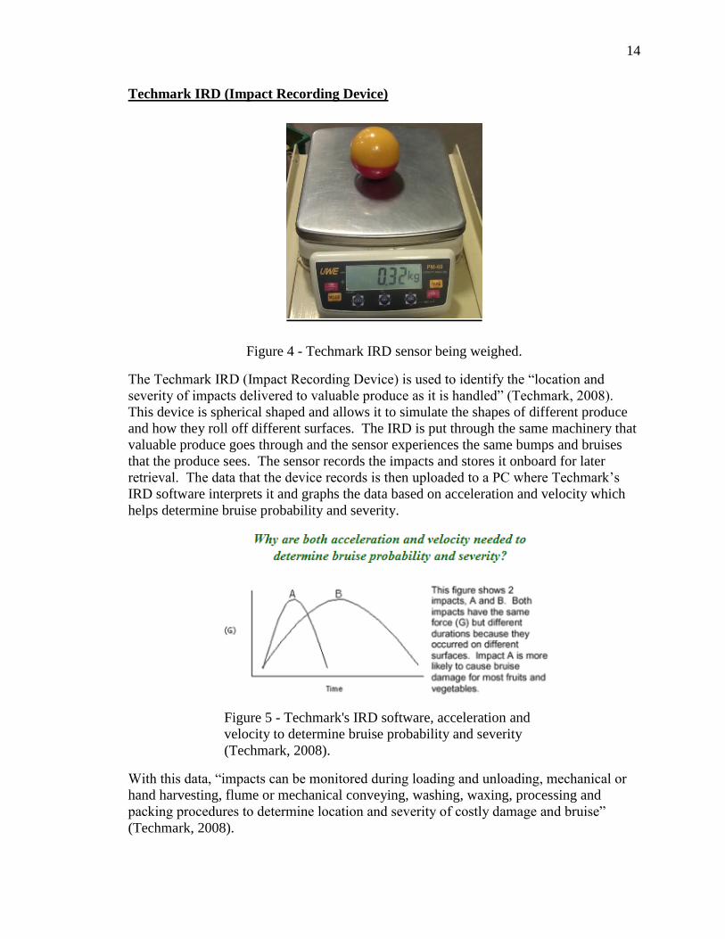
Techmark IRD (Impact Recording Device)
Figure 4 - Techmark IRD sensor being weighed.
The Techmark IRD (Impact Recording Device) is used to identify the “location and
severity of impacts delivered to valuable produce as it is handled” (Techmark, 2008).
This device is spherical shaped and allows it to simulate the shapes of different produce
and how they roll off different surfaces. The IRD is put through the same machinery that
valuable produce goes through and the sensor experiences the same bumps and bruises
that the produce sees. The sensor records the impacts and stores it onboard for later
retrieval. The data that the device records is then uploaded to a PC where Techmark’s
IRD software interprets it and graphs the data based on acceleration and velocity which
helps determine bruise probability and severity.
Figure 5 - Techmark's IRD software, acceleration and
velocity to determine bruise probability and severity
(Techmark, 2008).
With this data, “impacts can be monitored during loading and unloading, mechanical or
hand harvesting, flume or mechanical conveying, washing, waxing, processing and
packing procedures to determine location and severity of costly damage and bruise”
(Techmark, 2008).

15
PROCEDURES AND METHODS
Preliminary testing at Bee Sweet Packing Facility
Before designing the RPC dumper could be started, preliminary testing was done to
determine the damage based on dumping the oranges from RPCs. A visit to the Bee
Sweet packing house facility was made November 9-November 10, 2012. There, an
impact recording device was obtained from Dr. Andrew Holtz of Cal Poly San Luis
Obispo and was used to measure the different impacts that citrus fruit might observe
during the packing process at Bee Sweet Citrus.
Figure 6 - Dumping the RPC with Techmark Impact Recording Device (yellow and red
sphere).
At first, the impact recording device was put onto the navel packing line at Bee Sweet to
observe the amount of damage that a typical navel orange would see after being picked.
A video camera was also used to track the impact recording device to determine which
machines the device logged impacts for. Each video was thoroughly accessed and along
with the data logged from the impact recording device, each impact was linked to which
machine that the fruit sustained damage from. There were some outliers in the data since
Bee Sweet uses workers to visually sort citrus after the photo eyes for redundancy and
some of the workers would mistake the impact recording device as a rotten fruit.

16
The impact recording device was then put onto a navel bagging line to observe the
impacts that are typically seen when citrus runs through this line. The data from one of
the navel bag runs is shown below in Figure 7.
Figure 7 - RPC dump test data on a bagging line at Bee Sweet Citrus.
In the data shown from Figure 7, the impact sensor detected multiple impacts that were
within the range of padded surfaces. There were only two areas that the impact sensor
recorded the impacts that registered for steel surfaces. These two areas are: the metering
belt to the weigher and from the weigher into the bagger. Since there was no damage
threshold line for oranges on the impact recording device, the apple threshold line was
used as a baseline to determine the amount of damage that citrus might see since the
apple threshold line contained the lowest damage threshold.

17
Figure 8 - RPC test, impact sensor was on the top of the RPC towards the front.
From the data from Figure 8, multiple RPC dumping tests were done with the sensor
placed in different areas of the RPC. Figure 8, above, shows the results from the RPC
dump test where the sensor was on the top of the RPC towards the front of the conveyor.
Many tests were done and after much deliberation and consulting with workers that
dumped the RPCs, it was found that having the box stand vertical caused the least amount
of damage to the citrus. The surface type that the impact recording device registered for
most of the vertical orientation of the RPC was a padded surface (Figure 9).
Figure 9 - RPC test, impact sensor was on the bottom of the RPC towards the back.
18
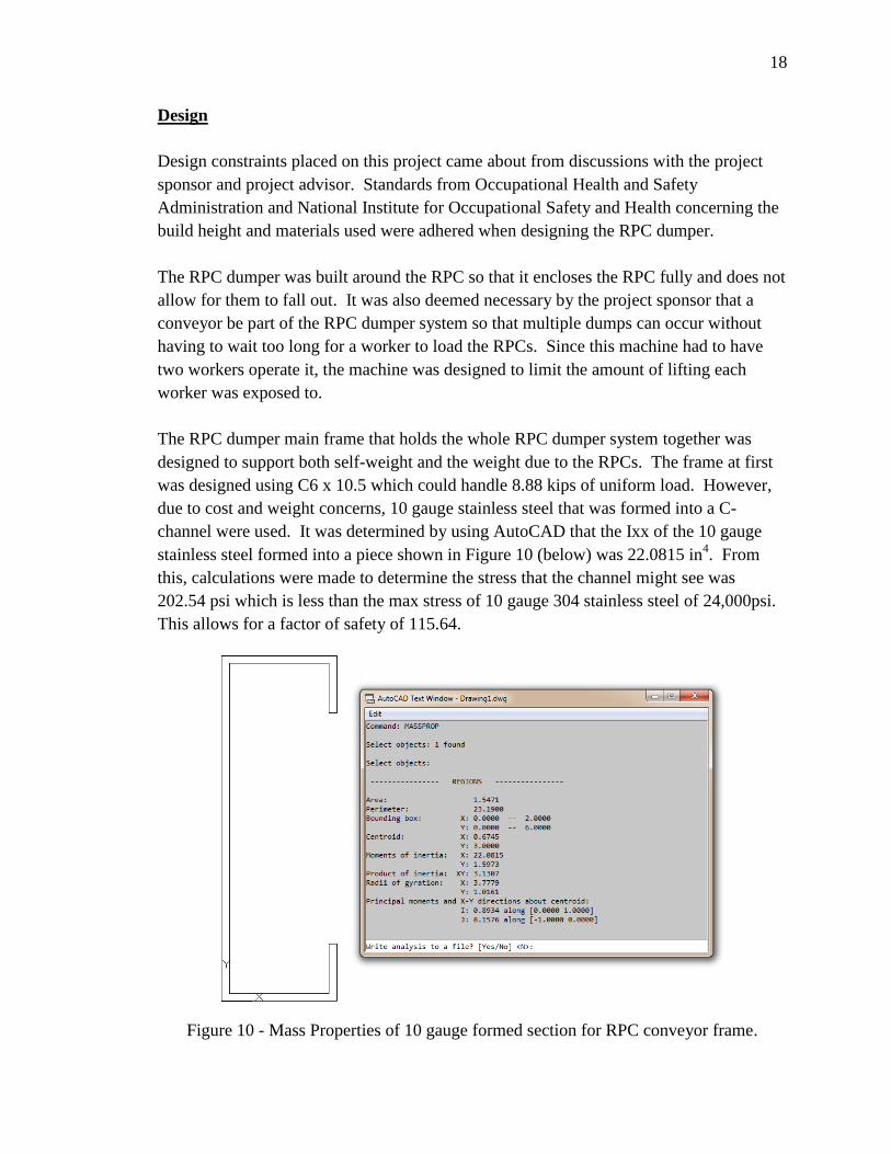
Design
Design constraints placed on this project came about from discussions with the project
sponsor and project advisor. Standards from Occupational Health and Safety
Administration and National Institute for Occupational Safety and Health concerning the
build height and materials used were adhered when designing the RPC dumper.
The RPC dumper was built around the RPC so that it encloses the RPC fully and does not
allow for them to fall out. It was also deemed necessary by the project sponsor that a
conveyor be part of the RPC dumper system so that multiple dumps can occur without
having to wait too long for a worker to load the RPCs. Since this machine had to have
two workers operate it, the machine was designed to limit the amount of lifting each
worker was exposed to.
The RPC dumper main frame that holds the whole RPC dumper system together was
designed to support both self-weight and the weight due to the RPCs. The frame at first
was designed using C6 x 10.5 which could handle 8.88 kips of uniform load. However,
due to cost and weight concerns, 10 gauge stainless steel that was formed into a C-
channel were used. It was determined by using AutoCAD that the Ixx of the 10 gauge
stainless steel formed into a piece shown in Figure 10 (below) was 22.0815 in4. From
this, calculations were made to determine the stress that the channel might see was
202.54 psi which is less than the max stress of 10 gauge 304 stainless steel of 24,000psi.
This allows for a factor of safety of 115.64.
Figure 10 - Mass Properties of 10 gauge formed section for RPC conveyor frame.

19
The mechanism that holds the RPCs while being dumped was constructed out of 2 x 2 x
0.187 square tubing. The reason why such thick tubing was used is because of the
customer’s input in that overtime, the impact of the dumper frame hitting the dumper rest
could cause the welds on the dumper frame to break. The dumper frame was also
designed so that it can operate with different sized RPC heights. Two 1.5” bore, 4 inch
stroke, pneumatic air cylinders raise and lower the dumper lid depending on the height of
the RPC. A single 1.5” bore, 8 inch stroke, pneumatic air cylinder opens and closes the
UHMW dumper lid to help prevent the citrus fruit from rolling out of the RPC dumper
prematurely. This lid will also allow a regulated release of the citrus fruit onto the roll-
off ramp which will allow the citrus roll off onto a conveyor belt rather than being
dropped onto it. A single 1.5” bore, 3 inch stroke, pneumatic air cylinder was then
designed with a mount to create the knife gate system. This system would sit in between
the PLC holders and lower dumper frame and ensure that boxes do not go past the end of
the dumper, which allows for the boxes to be dumped properly and within an enclosed
area.
The RPC dumper at first was designed to be dumped using a hydraulic system. However,
due to constraints on the dimensions and also customer input, they RPC dumper was then
designed to be dumped by a chain and sprocket system. With the chain and sprocket
system, a shaft size had to be determined so that it could handle the weight of the RPC
dumper and the amount of torque place onto it from a 2 HP Baldor motor. From the
calculations in the appendix B, a shaft size of 1.5” diameter of 1018 steel would be
sufficient and allow for a factor of safety of 1.338. From these calculations, it was also
determined that an 26 tooth, 80 pitch sprocket would have sufficient torque to power the
dumper if a 13 tooth, 80 pitch sprocket was attached to the 2hp motor.
Figure 11 - RPC dumper cradle design.

20
In order to attach the dumper system to the rest of the conveyor frame, a support system
was devised using 2” x 2” x 0.187” square tubing and 2” x 6” x 0.187” rectangular
tubing. The 2” x 6”x 0.187” rectangular tubing is used to support the bearings that will
house the 1.5” diameter shaft as well as the RPC dumper roll-off lid stopper. Legs that
will be made from the 2” x 2” x 0.187” square tubing will connect the rectangular tubing
to eh frame of the conveyor. Other legs will attach perpendicular to the 2” x 2” x 0.187”
square tubing and allow for the weight of the dumper system to be in direct contract with
the ground rather than having the conveyor frame support its weight. This method of
having the dumper system with direct contact with the ground allows it to be more stable
during dumping and does not allow for buckling in the flanges of the conveyor frame.
Since the RPC dumper had to be portable and be able to accommodate many different
conveyor heights, forklift guides that were 2” x 6” x 0.187” rectangular tubing were
places near the center of gravity of the dumper while the conveyor legs were constructed
out of 2 pieces of square tubing. The legs were constructed out of 2” x 2” x 0.187” and
1.5” x 1.5” x 0.187” square tubing. The 1.5” x 1.5” x 0.187” square tubing would slip
into the 2” x 2” x 0.187” square tubing allowing the conveyor 16 inches in vertical
adjustment. The 1.5” x 1.5” x 0.187” square tubing would be held in place inside the 2”
x 2” x 0.187” square tubing by two 3/8” x 1” long grade 5, fine thread bolts. The forklift
guides would then be attached to the two inner legs by the use of a horizontal support that
was made from 2” x 2” x 0.187” square tubing that would span from between the two
legs. Truss supports that attach to the horizontal support of the forklift forks helps
distribute the load to the conveyor legs near where they attach to the conveyor frame. As
picture of the legs and the location of the forklift guides can be seen below in Figure 12.
Figure 12 - Location of the forklift guides and design of adjustable legs.

21
The motor mounts for the 0.5hp Baldor motors, the 2hp Baldor motor, and their
respective gearboxes were designed using the shelves to help incorporate them into the
frame and attaching them to the most rigid places. The 2hp Baldor motor and its gearbox
were placed on a shelf so that it would be near the sprocket of the dumper, minimizing
the amount of chain required to operate the dumper. The gearbox was also placed on
unistruts to allow for further adjustments on chain tension. A truss like system was also
created for the shelf to help reduce the lever arm distance and to ensure that after repeated
relocations, the weight of the motor and gear box would not cause the shelf to bend
downward. Due to tight amount of space between the take-up of the outer conveyor
chain and the chain for the dumper, a idler sprocket had to be installed to help redirect the
chain away from the take-up. The Nylon Idler Sprocket W/Ball Bearing, 80 Chain, 12
Teeth, 3/4" Bore, required a 3/4 “ shaft to freely spin on and and a 3/4” nut to secure it
onto the threaded shaft.
The 0.5hp and gearbox that drives the inner chain was placed on a piece of 3/16” sheet
metal which spans the length of the conveyor and sits on the horizontal cross members
that hold the forklift forks in place. The reason why it spans the whole length is to create
a simply supported beam rather than a cantilevered beam. The gearbox also sits on
unistruts to also help with chain tensioning.
The 0.5hp motor and gearbox that drives the outer chain was placed directly on the shaft
for the sprockets. Since the gear box was a hollow bore gearbox, the gearbox could be
placed directly on the shaft which meant that most of the gearbox’s weight would be
directly supported by the shaft. With most of the weight supported by the shaft, a
mounting plate had to be designed to prevent the gearbox from torqueing and spinning
wildly when starting up the conveyor. The plate was designed to fit around one of the
conveyor legs and attach to the C-channel pieces that make up the conveyor frame (see
Figure 13).

22
Figure 13 - Mounting Plate and placement for 0.5hp Baldor motor for outer conveyor
chain.
Once the motor mounts had been designed, then the whole design was put together using
all of the different components such as the lower dumper frame, dumper cradle, conveyor
frame, motors, motor mounts, gearboxes, sprockets, and PLC. The whole project was
assembled in SolidWorks to ensure proper fit of all of the components and to determine if
there was any interference with different components. If there were interference, the
component was then moved around until it fit. Any changes made were reflected in the
model which was then transferred into the fabrication of the RPC dumper. A model view
of the finished RPC dumper can be seen below in Figure 14.

23
Figure 14 - Whole RPC dumper assembly.
Fabrication
After the design of the RPC dumper was finalized, a spreadsheet was created and each
different part of the RPC dumper was separated into categories and then by material in
order to use the least amount of materials (See Appendix F). With this spreadsheet, the
number of parts that were required was determined and then sent to Valley Iron Company
in Fresno, CA to get quoted.
After Valley Iron Company quoted the metal for the conveyor, a 4 ft. by 10 ft. sheet of 10
gauge 304 stainless steel was sent to Exeter Engineering to be bent into the C-channel
required for the conveyor frame. Once the conveyor frames had been cut to size and
shaped, Valley Iron then shipped the materials to the BRAE department. There,
fabrication started with conducting a run through of the materials received.
After a run through of the materials was conducted, the stainless steel tubing; 2” x 2” x
0.187”, 2” x 2” x 0.065”, 2” x 6” x 0.187”, and 1.5” x 1.5” x 0.187”, was cut on the band
saws in BRAE shop 7 at a feed speed of 80-100 fpm (feet per minute) and at a force of
~30lbs. This speed would ensure that the stainless steel would be cut accurately and not
damage the band saw since stainless steel is harder than regular steel. After each piece
was cut out on the band saw, they were then taken to a belt sander, located in Shop 6 and

24
in Shop 7, and the burrs from the stainless steel were then taken off. From that, the
pieces were then sharpied on with which part they belong to for better organization and to
allow for quick access to each part. Shown below is the organizational method used for
the parts for this project (Figure 15).
Figure 15 - Part organization for RPC dumper project.
Once all of the parts were cut out and organized, the parts that required MIG welding
were then separated from the rest of the parts to have their ends beveled to allow for
better penetration of the weld material. These parts were beveled using the 4 – ½”
grinder with a grinding disk attachment for stainless steel. The bevels were made at a 45
degree angle and left about 3/32” of thickness of the end material. The parts that mainly
comprised of the beveled parts were the lower dumper frame, the dumper cradle, and the
legs for the conveyor.
The lower dumper frame, the dumper cradle, and the legs for the conveyor were all MIG
welded using the red MIG welder that was set to stainless steel in BRAE shop 7. The
MIG welder, an IdealArc SP-200, was set up so that the coarse arc voltage control was
set to 18V-23V while the fine arc voltage control was set at 2.75V with a wire feed speed
of 150 ipm (inches per minute). At first the pieces were laid out according to how they
would be fabricated (see Appendix F). Then using large C-clamps, the pieces were then
clamped into place while they were being tack-welded. Once the pieces were tack
welded, they were double checked for squareness and to ensure that no warping had
occurred. After each part was tacked and checked, then they were welded together using
the MIG welder. Each piece was welded on one side and the let to rest so that the heat
from welding would dissipate from the stainless steel. This rest time would help reduce

25
the amount of warpage from welding since stainless steel has poor heat dissipation
properties. Once the dumper cradle and the lower dumper frame had been welded
together, they were then set aside so that other pieces of the conveyor could be fabricated
(Figure 16).
Figure 16 - Lower dumper frame and dumper cradle.
While the lower dumper frame was being welded together, the rest of the 10 gauge sheet
left over from the frame placed on the CNC plasma cutter in Shop 6 to cut out pieces that
include: the fruit roll-off lid, dumper cradle RPC guide rails, cap pieces for all parts, and
supports for the knife gate cylinder. The parts were drawn up in AutoCAD and converted
to a .dxf file. From there, the file was transferred to the computer in Shop 6 in which the
program FastCam was used to program the cut paths for the CNC plasma cutter (See
Figure 17).
Figure 17 - Using FastCam to program the cut paths for CNC Plasma Cutter.

26
Once the paths had been programmed on FastCam, the CNC plasma cutter then cut out
the pieces under the supervision of Dr. Mark Zohns. After the pieces had been cut out,
they were then removed from the plasma cutter’s grate and then labeled with the part’s
name. Then the portable plasma cutter was wheeled out from Shop 7 and the remaining
sheet of 10 gauge stainless steel was trimmed down so save on space and weight. The
trimmed pieces were then placed in a pile so that they could later be recycled by Bee
Sweet.
After the trimming process had finished, then the conveyor legs were then welded
together. First, the 3” x 3” squares for the feet of the legs were located amongst the many
assorted parts on the project cart. Once they had been located, a combination square was
used to center the 1.5” x 1.5” x 0.187” square tubing in the center of the 3” x 3” square
foot. With the square tubing centered, they were then tacked in place using the stainless
steel MIG welder. After the legs had been tacked to the feet, they were then checked for
squareness using the combination square. Once the legs had been verified that they were
square, then they were completely welded up, taking intermittent breaks in-between
welds to ensure no heat warpage. While the legs and feet were being welded together,
the holes for which the bolts that allow for the legs to extended were being drilled out for
the 2” x 2” x 0.187” square tubing. The holes were drilled on two adjacent sides of the
square tubing, in the center and 1 inch from the end of one side of the square tubing. The
holes were first drilled out using a center drill bit in one of the drill presses in Shop 7.
After the holes had been drilled, the bolts are screwed into the nuts and placed into each
hole that was drilled into the tubing and then tacked into place. The bolts were then
removed and the whole nut was welded into place. Once the whole nut was welded onto
the square tubing, a 3/8” – 28 tap was used to clean out any foreign objects and also help
prevent the bolts from gumming up in the nut due to heat warpage. However, one bolt
did become stuck in the nut and during the process of removing it; the bolt broke in
torsional shear as seen below in Figure 18.
Figure 18 - Bolt that sheared inside the nut.

27
In order to remove the broken bolt, a bolt extractor was used along with one of the drill
presses in Shop 7. First, a small drill bit was used to drill a pilot hole into the broken
bolt. Then an extracting bit was inserted into the hole made by the pilot bit, and a pair of
vise grips was used to grab the extracting bit. The vise grips were then turned counter-
clockwise with pressure being applied constantly. This caused the bit to dig into the
broken bolt and begin to pull it out. Once the broken bolt had been removed, the 3/8” –
28 tap was then run through the nut to remove metal filings and clean up the threads of
the nut.
After the broken bolt had been removed from the nut, the end caps for many different
components of the dumper assembly and cradle system were TIG welded into place. A
Miller Dynasty 200 DX AC/DC TIG welder was used to TIG the end caps on. First, a
TIG (GTAW) calculator was used to figure out the correct settings for the TIG welder
along with the correct size tungsten rod to use for the welder. The settings that were
selected go as follows: pulser: on, amperage: 110A, post flow: 5.5 secs, DC polarity,
process: TIG HF impulse, output: RMT STD, and argon flow: 23CFH. After the TIG
welder had been set up to the appropriate settings, a couple of scrap stainless steel were
used as test pieces to confirm that the TIG welder had been set up to the appropriate
settings. With the TIG set up correctly, the caps for the different components of the
dumper assembly and cradle system were first tacked in place and then welded on
carefully to ensure that the heat would not warp the tubing. Once all of the caps had been
TIG welded, a wire bush was used to clean off the weld, see Figure 19.
Figure 19 - TIG welds before and after wire brush cleaning (before: left, after: right).
While the caps for the different components of the dumper assembly and cradle system
were being TIG welded, some heat warpage was discovered on the dumper cradle;
mainly the piece of 10 gauge sheet metal that helps catch and lift the RPCs were warped
and squeezed the RPC too tight and would not allow for the RPCs to be removed easily.
In order to fix this, the oxyacetylene torch was used to heat back up some of the parts and

28
a lot of hammering was used to help reshape the part. For some of the parts that did not
want to reshape properly, their welds were ground off and the part was then recut to size
and MIG welded back into place. A lot of support beams were used during the MIG
welding process to ensure that there would be no more heat warping of those parts.
After the heat warpage on the RPC cradle had been fixed, the CNC plasma cutter was
then used to cut out parts for the dumper lid, motor mounts, UHMW lid side mounts, and
knife gate components. The cuts were programmed in FastCam and cut by Dr. Mark
Zohns. Once the pieces had been cut out, the roll-off lid and the UHMW lid side mounts
were then brought to the HydraBend press break in order to bend flanges at 90 degrees
into them. The equation used to bend the material was:
Bend distance from edge of die = (die width)/2 – material thickness
Using the above equation, the point of the bend was calculated and distanced from the
edge of the die.
Once the roll-off lid and UHMW lid side mounts had been formed, the inner chain
supports were cut to size. The inner chain supports were made from 3” angle that was
3/16” thick and 19.5” long. The band saw was used along with a custom setup in order to
make the difficult cuts for the piece (see Appendix G). The custom setup consisted of
two 1/4” thick pieces that were used as the stopper and the guide point (Figure 20). This
allowed for all of the inner chain supports to be cut to the same width and depth.
Figure 20 - Band Saw setup to cut inner chain supports to size.
After all of the inner chain pieces had been cut to size, the RPC back stop was then cut.
The RPC back stop was made from 3” angle that was 3/16” thick and 35” long. Since the
RPC back stop would stop RPCs a certain distance away from the edge of the conveyor
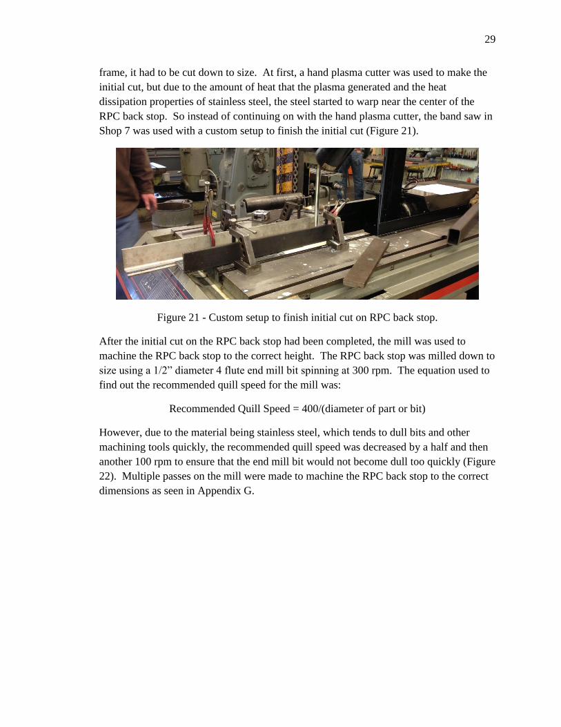
29
frame, it had to be cut down to size. At first, a hand plasma cutter was used to make the
initial cut, but due to the amount of heat that the plasma generated and the heat
dissipation properties of stainless steel, the steel started to warp near the center of the
RPC back stop. So instead of continuing on with the hand plasma cutter, the band saw in
Shop 7 was used with a custom setup to finish the initial cut (Figure 21).
Figure 21 - Custom setup to finish initial cut on RPC back stop.
After the initial cut on the RPC back stop had been completed, the mill was used to
machine the RPC back stop to the correct height. The RPC back stop was milled down to
size using a 1/2” diameter 4 flute end mill bit spinning at 300 rpm. The equation used to
find out the recommended quill speed for the mill was:
Recommended Quill Speed = 400/(diameter of part or bit)
However, due to the material being stainless steel, which tends to dull bits and other
machining tools quickly, the recommended quill speed was decreased by a half and then
another 100 rpm to ensure that the end mill bit would not become dull too quickly (Figure
22). Multiple passes on the mill were made to machine the RPC back stop to the correct
dimensions as seen in Appendix G.

30
Figure 22 - Using the mill to machine the RPC back stop to size.
Once the RPC back stop had been machined, the inner chain pillow block supports which
mount onto the lower conveyor frame and the PLC holders were machined from 2” x 2” x
0.187” square tubing that were11.875” long. The band saw was used to cut notches in
the tubing so that it would rest on other 2” cross tubing members. After the notches had
been cut out on the band saw, the mill was used to drill out the holes in order to mount
the pillow block bearings. First an edge finder was used to locate and zero the x and y-
axis edges of tubing. After the edges have been located, a small center drill bit was used
to drill the initial drill hole which would help center the subsequent drill bits used to drill
the hole to size. Three drill bits were used to step up to the final drill bit and each drill bit
required a different R8 adapter size ranging from 1:4 to 2:4 along with and R8 to Morse
taper adapter.
Figure 23 - Second step-up drill bit to get pillow block bearing slots to size.

31
Once the holes had been drilled to the pillow block bearing slot size, a 2 flute, 1/4" end
mill bit was then used to further mill out the slot. After the slots had been milled out,
they were then sanded down to remove any burrs left behind from milling the slots. Then
the end caps of the inner chain pillow block supports were then TIG welded onto the
inner chain pillow block supports.
While the inner chain pillow block supports were being fabricated, the conveyor frame
was being assembled from the four different C-channel pieces that were bent and
fabricated by Exeter Engineering. The pieces were set on top of two welding tables in
Shop 6 and then squared up using a combination of tools such as a tape measured,
squared, and level. Once the conveyor frame and been squared, the various pieces were
then tacked into place using the MIG welder. After the conveyor frame had been tacked,
the whole frame was then moved into Shop 7 where it was TIG welded together. Lots of
care and constant rotation between welds were made to ensure that the conveyor frame
did not warp and twist in any direction. Immediately after the conveyor frame had been
TIG welded together, pressurized shop air was run over the conveyor frame to cool it
down so that the RPC box stoppers could be welded on. Once the frame had cooled to
room temperature, the RPC box stoppers were welded on at the end of each conveyor
cross members using the TIG welder. After the RPC box stoppers had been TIG welded
into place, the RPC back stop was then welded onto the conveyor frame. The RPC back
stop needed a custom setup in order to get it to the correct height for it to be welded onto
the conveyor frame. This setup consisted of 2” x 6” x 0.187” rectangular tubing that was
cut to 5.5” long and various pieces of steel that the RPC back stop would rest on while
being welded onto the frame. Lots of 1/8” stainless TIG filler rod was used to weld the
RPC back stop onto the frame due to the fillet on the C-channel.
Once the RPC back stop and RPC box stoppers had been welded onto the conveyor
frame, the inner chain supports were welded into the frame and MIG welded into place.
Due to some heat warpage from the TIG welding of the frame, the inner chain supports
had to be trimmed down a bit so they would fit into the conveyor frame. While the inner
chain supports were being welded into the conveyor frame, the rectangular tubing that the
weldon hubs would be attached to had to be machined so that the weldon hub would fit
on one side of the tubing and allow for the shaft to go through both sides. At first, the 2”
x 6” x 0.187” rectangular tubing was center drilled on the mill for accuracy on both sides.
Then, one of the sides was drilled out to 1-33/64” diameter using the Carlton drill press.
After one side of the rectangular tubing had been drilled with the 1-33/64” drill bit, the
rectangular tubing pieces were then taken to the mill where the weldon hub hole would
be drilled on the other side of the tubing. At the mill, a 1-3/4” hole saw was used to drill
out the initial hole for the weldon hub while a criterion boring bar was used to widen the
hole to the specified diameter of the weldon hub.

32
Figure 24 - Using the criterion boring bar to widen up hole for the weldon hub.
Once the rectangular tubing for the weldon hubs had been machined to size, the bearing
and shaft holes in the conveyor frame were widened using a die grinder. The holes were
enlarged to allow for easier installation of the bearings and shafts and to allow for small
height adjustments. While the holes on the conveyor frame were being enlarged, the
knife gate which is used to stop the boxes inside of the dumper cradle was TIG welded
together. The knife gate consisted of two 3/16” plates with each side having an
additional 3/16” flange in order to stop the knife gate at certain points. Once the knife
gate had been TIG welded, a 3/8” hole was drilled on one side, in between the flanges to
allow for a clevis pin from an air cylinder to attach to it.
After the knife gate had been welded together and the clevis pin for the air cylinder had
been installed, the inner chain support which would hold the knife gate was drilled and
taped for a 1/4” -28 thread bolt in which a piece of 3” angle would hold the UHMW rails.
The UHMW rails were drilled with a 13/32” drill bit and then countersinked with a 90
degree taper. Once the knife gate had been placed in the rails, a mounting system was
then fabricated using 10 gauge stainless steel, in which the 3” stroke air cylinder for the
knife gate would bolt into it. After the air cylinder mount had been fabricated, it was
then set aside to be later installed when the lower conveyor frame and the PLC holders
had been welded onto the conveyor frame.
While the air cylinder mount for the knife gate was being fabricated, the conveyor frame
and the lower conveyor frame were welded together. This step in the fabrication of the
RPC dumper required a lot of finesse since the RPCs had to be lined up just right in order
to go into the RPC dumper cradle. However, in order to line up the RPCs just right, the
whole RPC dumper had to be put together even with components not fully finished. The
1.5” diameter shaft was used to support one side of the RPC cradle while a 2” x 6” x
0.187” rectangular tubing with extra pieces of 10 gauge steel were used to hold the other
side (see Figure 25).

33
Figure 25 - RPC dumper mocked up in order to correctly distance conveyor frame from
lower conveyor frame.
With this setup, the movement of RPCs was simulated to obtain the best distance from
the edge of the conveyor frame to the edge of the lower conveyor frame in which RPCs
could move freely in and out of the RPC cradle without any obstruction. When the
optimal distance had been found, the conveyor frame and lower conveyor frame were
then tacked and the distance was then double checked. Once the distance had been
double checked, then the lower conveyor frame and the conveyor frame were MIG
welded into place.
After the conveyor frame had been welded to the lower conveyor frame, the RPC cradle
rest was welded to the conveyor frame. In order to weld the RPC cradle rest on, the RPC
cradle had to be reinstalled on the dumper shaft and spaced equal distantly from inside
faces of the lower dumper cradle. Once the dumper cradle had been spaced, a 2” x 6” x
0.187” rectangular tubing was placed across the inner chain supports and the knife gate
support. On top of this went a small hydraulic jack with a 6 inch stroke with a piece of
C6 x 10.5 which held up the dumper cradle by lifting the lid. Two levels were then used
to ensure that the dumper cradle was level with the ground. After the dumper cradle had
been leveled, the dumper cradle rest was then clamped onto the RPC catcher on the
dumper cradle by using C-clamps and vise grips. Once the dumper cradle rest had been
clamped into place, it was then tacked and checked for squareness and how level it was.
Once the dumper cradle rest had been checked, it was then fully welded on using the
MIG welder.

34
Figure 26 - Setup used to weld dumper cradle rest to conveyor frame.
After the dumper cradle rest had been welded on, the dumper cradle was then removed
from the assembly so that the counter weights could be welded onto it. At first, the
counter weights were welded onto a piece of 2” x 2” 0.187” square tubing under each of
2” x 6” x 0.187” rectangular tubing that the weldon hubs were attached to. Due to
concerns about the amount of weight and the thickness of the tubing that enclosed the
weights for the counterweight system, which had a wall thickness of 0.065” , another 2” x
2” x 0.187” square tubing was welded onto the 2” x 6” x 0.187” rectangular tubing that
the weldon hubs were attached to. This allowed for more support of the weight and
therefore decreased the amount of load on one of the counterweight enclosures.
Once the counterweights had been welded onto the dumper cradle, a forklift was used to
move the whole conveyor system into Shop 6 so that the gantry hoist could be used to
lower the dumper cradle into the conveyor frame. Multiple straps were used to hoist the
dumper cradle due to it being heavy on one side and also to keep it level while it was
being lowered into the conveyor frame. Once the dumper cradle had been lowered into
place, the dumper shaft was then installed so that it would hold the dumper cradle while
the straps for the gantry hoist were loosened.

35
Figure 27 - Gantry hoist used to help lift and install dumper cradle onto conveyor frame.
After the dumper cradle had been installed, the straps were repositioned so that they
could help replicate the dumping action of the dumper cradle since the VFD had not been
programmed yet. One problem that was discovered when the dumping action was being
replicated was that the RPC catcher on the dumper cradle was catching the conveyor
chain, causing the conveyor chain to derail from the UHMW chain guides. This problem
was due to the RPC catcher being too wide and that the UHMW chain guides were too
narrow for the chain to fit in. In order to mitigate this problem, the RPC catcher was
shortened so that it would not interfere with the dumping function of the RPC cradle and
the UHMW was widened using a die grinder so that the chain would better fit in the
UMHW chain guides.
After the modifications had been made to the chain guides and the RPC catcher, the
dumper cradle stopper was then fabricated out of 2” x 2” x 0.187” square tubing. This
part would help stop the dumper cradle in case the brake of the VDF could not stop it.
The hand band saw and a cut off wheel were used to fabricate this piece due to the
complex design in which it had to stop the dumper cradle at 45 degrees and that it had to
allow for the dumper cradle to clear it during its dumping routine. After the piece had
been fabricated, it was then placed on the roll-off lid support bar and stick welded on.
Multiple clamps were used to help secure the dumper cradle stopper during the welding
process to ensure that the stopper did not move from the force being applied to the stick.
Multiple passes were made with the stick welder due to the angle and the space available,
which caused some of the welds to not come out properly. After the dumper cradle
stopper had been welded on, the whole RPC dumper assembly was then wiped down with
acetone and prepped for testing.
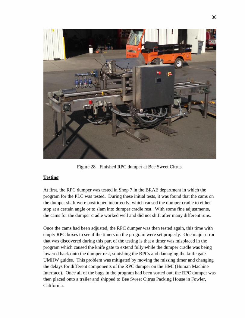
36
Figure 28 - Finished RPC dumper at Bee Sweet Citrus.
Testing
At first, the RPC dumper was tested in Shop 7 in the BRAE department in which the
program for the PLC was tested. During these initial tests, it was found that the cams on
the dumper shaft were positioned incorrectly, which caused the dumper cradle to either
stop at a certain angle or to slam into dumper cradle rest. With some fine adjustments,
the cams for the dumper cradle worked well and did not shift after many different runs.
Once the cams had been adjusted, the RPC dumper was then tested again, this time with
empty RPC boxes to see if the timers on the program were set properly. One major error
that was discovered during this part of the testing is that a timer was misplaced in the
program which caused the knife gate to extend fully while the dumper cradle was being
lowered back onto the dumper rest, squishing the RPCs and damaging the knife gate
UMHW guides. This problem was mitigated by moving the missing timer and changing
the delays for different components of the RPC dumper on the HMI (Human Machine
Interface). Once all of the bugs in the program had been sorted out, the RPC dumper was
then placed onto a trailer and shipped to Bee Sweet Citrus Packing House in Fowler,
California.

37
At Bee Sweet Citrus Packing House, the RPC dumper was thoroughly tested with
multiple dump test as well as using an IRD sensor to measure the impacts that citrus
being dumped may observe. Shown below is the test setup for the RPC dumper (Figure
29).
Figure 29 - Test setup for RPC dumper at Bee Sweet Citrus Packing house.
The tests that were ran at Bee Sweet Citrus Packing House consisted on dumping Murcott
oranges that were being sent to juice and seeing how fast the RPC dumper can dump the
citrus. An impact recording device was used to record the change in velocity, impact
duration, and the maximum acceleration that citrus might observe when it is being
dumped by the RPC dumper (see Figure 30). Also during the test, multiple changes were
made to the PLC (Programmable Logic Controller) in order to help speed up the amount
of RPCs dumped per minute.

38
Figure 30 - Using the IRD sensor to measure impact data from the RPC dumper.

39
RESULTS
General Observations.
The RPC dumper is fully operational and portable so that it can be moved around Bee
Sweet Citrus. The PLC program is fully functional and with the current program, 4 RPCs
can be dumped per minute. During the dumping phase of the RPC dumper, the dumper
cradle impacts the dumper cradle stoppers with enough force to slightly rock the RPC
dumper.
Impact Recording Device Results.
An impact recording device was used to determine the force of impact, velocity change,
and the impact duration that citrus might see when being dumped by the RPC dumper.
During the testing of the RPC dumper, the IRD sensor was used multiple times so that an
average damage force, velocity change, and impact duration could be determined. From
the IRD sensor, graphs were constructed using TechMark’s IRD program which showed
the G-force and the velocity change (See Figure 31).
Figure 31 - IRD sensor graph of amount of damage seen by fruit when being dumped by
RPC dumper.
From the results displayed by the IRD sensor, the damage that the fruit sees is not
significant since the amount of damage that the fruit will see is similar to it being dropped

40
onto a padded surface. However, when compared to the preliminary test that were taken
in November for manually dumping the RPCs, the RPC dumper saw an 80% decrease in
velocity change and a 38% decrease in impact duration (see Tables 7 & 8 below).
Table 7 - IRD sensor data from manually dumping RPCs.
Table 8 - IRD sensor data from RPC dumper.
NIOSH Recommend Weight Limits.
Height measurements were taken for both manually dumping the RPCs and the using the
RPC dumper. These heights were plugged into the NIOSH lifting equation which helps
dictate the recommended weight limit (RWL) for a certain task. The RWLs for each;
manually dumping RPCs and using the RPC dumper were calculated and then tabulated
for comparison. Shown below are the AutoCAD drawings for the height of each task as
well as weights for each task (see Figures 32 & 33). From the NIOSH lifting equations,
manually dumping RPCs had a lower RWL than using the RPC dumper when the
frequency of lifting was 2 boxes per minute for a duration greater than 2 hours but less 8
hours. The RPC dumper has a 16% increase in RWL compared to manually dumping
RPCs which would allow workers to work longer without fear from sustaining lower
back injury.

41
RPCs stacked 8 highon pallets
6 ft 5.5 inches
Conveyor @ 20" high
40 lbs
20 inches
23.25 inches
21.5 inches
Manually Dumping RPCs
Figure 32 - AutoCAD drawing of the vertical heights and lifting weights for manually
dumping RPCs.
(1)
Where,

42
RPCs stacked 8 highon pallets
40 lbs
33 inches
7.5 inches6 ft 5.5 inches
RPC dumper loadingzone
RPC Dumper
Figure 33 - AutoCAD drawing of the vertical heights and lifting weights for using the
RPC dumper.
(1)
Where,

43
DISCUSSION
Construction phase took longer than anticipated. This was due in part to incorrectly
estimating required shop time and the number of changes made to the design during the
construction phase. Examples include using a sprocket that was too large for the dumper
cradle and would interfere with boxes going into the dumper; the chain used for the
dumper would also interfere with the conveyor shaft bearings and take-up supports, and
the heat dissipation properties of stainless steel.
The original design called for a 36 tooth, 80 pitch chain sprocket which would be placed
on the dumper shaft. This sprocket size would allow for more torque to be applied to the
dumper shaft and help lift the dumper cradle when it is fully loaded with RPCs full of
citrus. Upon further observation, it was then noted that the sprocket diameter was too
large and would interfere with the RPCs entering the dumper cradle. Also because of its
large size, the sprocket would cause the chain for the RPC cradle to rub against the take-
ups for the conveyor shaft pillow block bearings. So a 26 tooth, 80 pitch chain sprocket
was selected instead of the 36 tooth sprocket since it had the needed clearance so that the
boxes could pass by it without any interference. An idler gear was also implemented to
help move the chain so that it would not interfere with the take-ups.
In addition to spending a lot of time of redesigning the idler, a lot of time was spent on
ensuring that the stainless steel parts did not warp due to the excessive amount of heat
that was generated from welding and plasma cutting. Lots of time was spent clamping
down parts to ensure that no warpage would occur and also repositioning clamps so that
welds could be made. On top of that, more time was even spent on cooling down the
parts with compressed shop air so that more welds could be made. Another factor that
also caused for the increase fabrication time was the fabrication of special support
structures to help ensure that no warpage would occur.
Other things that accounted for lost time was the placement of the roll-off lid stopper and
the modification of the dumper cradle stopper. A guideline of a 45 degree angle for the
roll-off lid was used at first, however due to constraints on the location of the dumper
cradle stoppers, it was then moved to a different location since the roll-off lid stoppers
would interfere with the operation of the dumper cradle stoppers. So instead of using a
45 degree angle guideline, the guideline was decreased to a 30 degree angle. The dumper
cradle stopper went through many modifications that took up valuable time during the
last couple of weeks due to the constraints placed on it. The dumper cradle stopper
needed to stop the dumper cradle at a 45 degree angle and allow for the dumper cradle to
function unobstructed, while being strong enough to withstand the impact of the dumper
cradle. A complex design was used to solve this problem in which it allowed for both
functionability and strength of the dumper cradle stopper.

44
For the safety of operating this machine, sheet metal convers were fabricated and
mounted to cover the main dumper sprocket for the RPC dumper. This cover acts as
protection from the power drive of the dumper cradle to the RPCs and also to workers
loading RPCs onto the machine. The dumper cradle for the machine is shielded by the
PLC enclosure itself. There is an opening near the back side of the PLC enclosure to
allow for the dumper cradle to function properly. Even though the machine is shielded
by sheet metal and the PLC enclosure, proper safety precautions are always advised,
especially near pinch points such as where the dumper cradle rest and the dumper cradle
contact.

45
RECOMMENDATIONS
There is potential for improvement for the amount of acceleration seen in the IRD sensor
and also the amount of oranges that fell off of the conveyor belt due to the amount of
oranges being dumped at one time. The IRD sensor registered a 15% increase in
acceleration or G-force that the fruit saw during the dumping phase of the RPC dumper.
This was due to the IRD sensor hitting the stainless steel lid of the RPC dumper.
Incorporating some sort of foam padding onto the stainless steel lid would help reduce
the amount of G-force that the citrus would see when the dumper cradle is rotated.
Another implementation that could help decrease the amount of G-force that the citrus
sees is to move the proximity sensor on the lid retract pneumatic cylinder. This would
help decrease the amount of citrus released at one time which will also decrease the
amount of G-force that the citrus would see.

46
REFERENCES
Budynas, Richard G., and J. Keith Nisbett. 2011. Shigley’s Mechanical Engineering
Design. 9th
ed. New York, NY. McGraw-Hill.
Burkner, P.F., J.H. Chesson, and G.K. Brown. 1972. Padded Collecting Surfaces for
Reducing Citrus Fruit Injury. Transactions of the ASABE: 627-629.
CAL OSHA. 2013. Overview.
http://www.dir.ca.gov/dosh/ (verified 23 January)
Miller, W.M. and C. Wagner. 1991. Florida Citrus Packing Line Studies with an
Instrumented Sphere. American Society of Agricultural Engineers 7(5): 557-581.
OSHA.gov. 1997 . Conveyors 1917.48.
http://www.osha.gov/pls/oshaweb/owadisp.show_document?p_id=10385&p_tabl
e=STANDARDS (verified 20 November)
OSHA.gov. 2004. Power Transmission 1910.219.
http://www.osha.gov/pls/oshaweb/owadisp.show_document?p_id=9847&p_table
=STANDARDS (verified 20 November)
Techmark-inc.com. 2008. Impact Recording Devices.
http://www.techmark-inc.com/ird.asp (verified 9 November)
Waters, T. R., V. Putz-Anderson, and A. Garg. 1994. Applications Manual for the
Revised NIOSH Lifting Equation. U.S. Department of Health and Human
Services.

47
APPENDIX A – How the Project Meets the Requirements for the BRAE Major

48
HOW PROJECT MEETS REQUIREMENTS FOR THE BRAE MAJOR
Major Design Experience
The BRAE senior project must incorporate a major design experience. Design is the
process of devising a system, component, or process to meet specific needs. The design
process typically includes fundamental elements as outlined below. This project
addresses these issues as follows.
Establishment of Objectives and Criteria. Project objectives and criteria are
established to meet the needs and expectations of Bee Sweet Citrus.
Synthesis and Analysis. The project will incorporate bending stress calculations,
creating a mock PLC program, and optimization of VFD controls based on fruit damage.
Construction, Testing, and Evaluation. The RPC dumper will be designed,
constructed, and tested.
Incorporation of Applicable Engineering Standards. The project will utilize AISC
standards for allowable bending stresses, IEEE standards for electrical components,
ANSI standards for impact resistant safety glass, and OSHA standards for safety
precautions.
Capstone Design Experience
The BRAE senior project is an engineering design project based on the knowledge and
skills acquired in earlier coursework (Major, Support and/or GE courses).
BRAE 129 Lab Skills/Safety
BRAE 133 Engineering Graphics
BRAE 151 AutoCAD
BRAE 152 SolidWorks
BRAE 216 Fundamentals of Electricity
BRAE 234 Mechanical Systems
BRAE 328 Measurements and Computer Interfacing
BRAE 421/422 Equipment Engineering
ME 211/212 Engineering Statics/Dynamics
CE 204/207 Strength of Materials
IME 141 Welding
IME 142 Machining
IME 319 Human Factors Engineering
ENGL 149 Technical Writing
Design Parameters and Constraints
This project addresses a significant number of the categories of constraints listed below.

49
Physical. The machine must be able to fit an RPC (Reusable Plastic Container) that is
23” x 15.75” x 10”. The machine must also be smaller than 15 ft. long, 5 ft. high, and 5
ft. wide.
Economic. A team of two workers will be sufficient to operate the machine; one to load
RPCs and one to unload RPCs.
Ergonomics. A benefit of the project will be to reduce the stress on workers due to them
having to lift and dump RPCs which can weigh in excess of 40 lbs. This machine will
allow for a lower loading table and dump the RPCs for the workers.
Health and Safety. The RPC dumper will utilize a breaker for Lock-out Tag-out. A
chain guard will keep the conveyor chain covered and ensure good GMP procedures.
Aesthetic. The machine will be fabricated using stainless steel to provide ease of
sanitation. No paint will be applied to this machine since it will be installed into a food
processing environment.
Other – Productivity. The machine must be able to dump 4 RPCs per minute or 240
RPCs per hour. The machine must also be able to dump the RPCs slowly enough so that
the fruit is not damaged. A program for a PLC must be able to control the dumper and be
implemented easily into the RPC dumper.

50
APPENDIX B – Design Calculations

51
Dumper Shaft Design Calculations.
2hp @87.5rpm 4.657" Dia
8.836" Dia
155 lbs155 lbs
A
4.0" 35.0" 4.0" 3.0"
Figure 34 - Shaft Diameter Calculation Drawing
( )
( )

52
Mc/I
TR/J
TR/J
Mc/I
Figure 35 - Stress Block for Section A
( ) (
) ( )
( )
( )
( ) ( )
(
) ( ) ( )
( )
( )
( ) ( )

53
6.2979
12.4671 25.0629
18.7650
13.2689
x
y
t xy
sn
Figure 36 - Mohr Circle for Section A
√(
)
(
)
σn
τn

54
Different Shaft diameter sizes based on Factor of Safety
Table 9- Different Dumper Shaft Size Based On Factor of Safety
Factor of Safety Recommended Diameter (inches)
1.0 1.05
1.1 1.155
1.2 1.26
1.3 1.365
1.4 1.47
1.5 1.575
1.6 1.68
1.7 1.785
1.8 2.89
*** Assumes worst case scenario

55
Conveyor Frame Stainless Steel Size Selection.
C- Channel Sheet metalGauge Size Calculations
W = 7.27 lb/in
R1 R2 R3 R4
34.5000 34.5000
110.0000
Figure 37 - Forces and reactions on conveyor frame
( )
(
) ( )
(( ) ( ) )
( ) ( )
( ) ( )

56
(
) ( )
( )
( )
Use larger of moments for calculations
Moment of Inertia for C-channel:
Mass Properties of 10 gauge and 16 gauge shown in Appendix C
10 Gauge: I =
16 Gauge: I =
(Budynas et al, 2011).
10 gauge:
(
)
F.O.S = 115.64
16 gauge:
(
)
F.O.S = 53.14
Use 10 gauge due to F.O.S and to bolt bearings to.

57
Sizing the support cylinders for the lid open/close.
6.5000 6.5000 12.500012.5000
38.0000
50 lbs 63.4 lbs 50 lbs
A B
Figure 38 - Loads on dumper lid
Assume a F.O.S. of 2
Double the load amounts
Σ
Σ
( ) ( ) ( ) ( )
( )
( )

58
From Tables acquired from SMC courtesy of Thomas Turner (See Appendix D)
PSI = 90 psi
Bore Area lbs per cylinder
¾” 0.441786 in^2 39.76 lbs
1 1/8” 0.994 in^2 89.46 lbs
1 ½” 1.767 in^2 159.03 lbs
2” 3.14 in^2 282.6 lbs
PSI = 125 psi
Bore Area lbs per cylinder
¾” 0.441786 in^2 53.01 lbs
1 1/8” 0.994 in^2 119.28 lbs
1 ½” 1.767 in^2 212.04 lbs
2” 3.14 in^2 376.8 lbs
Use 1 ½” bore cylinders at 125 psi.

59
APPENDIX C – AutoCAD Mass Properties
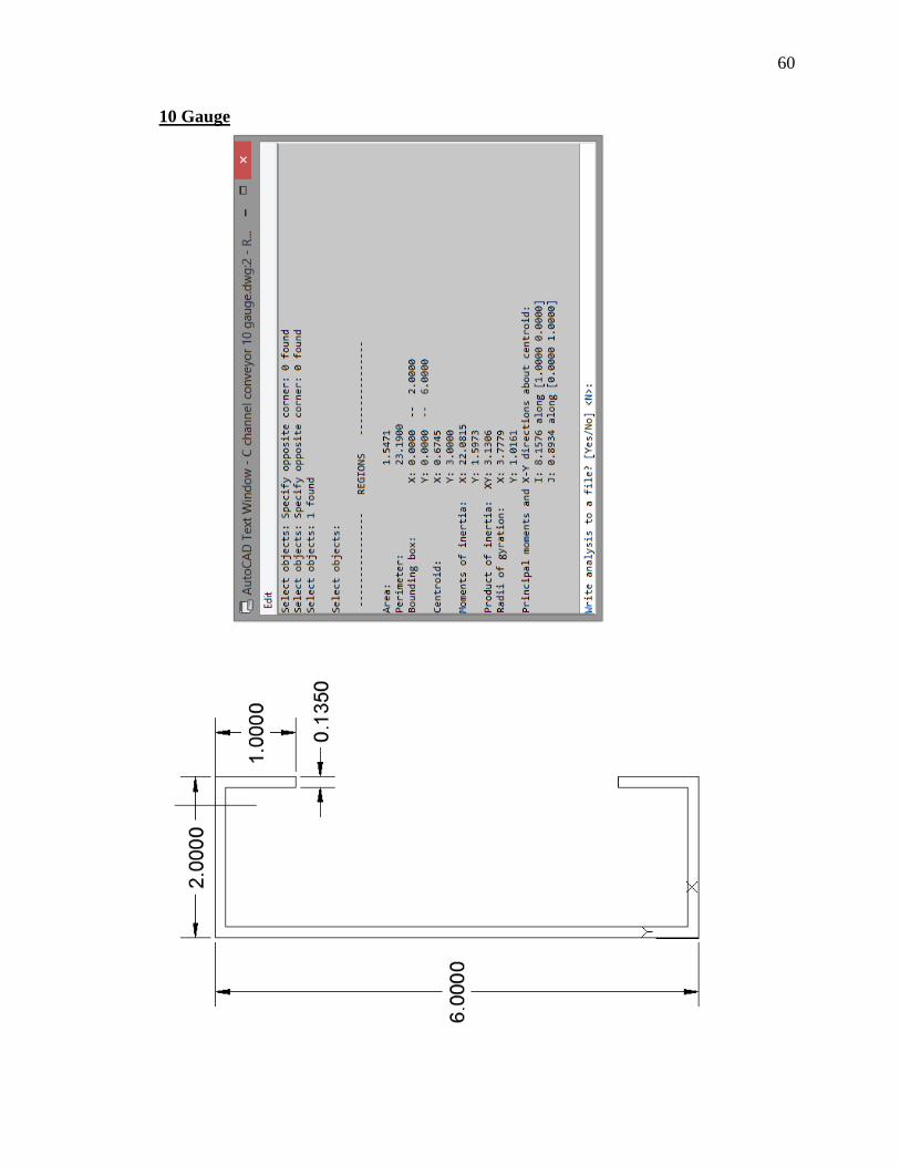
60
10 Gauge

61
16 Gauge

62
APPENDIX D – SMC Cylinder Force Chart

63
CYLINDER FORCE CHART(IN POUNDS FORCE)
BORE SIZE IN MILLIMETERS
2.5 4 6 8 10 12 15 16 20 25 32 40 50 63 80 100
10 0.08 0.19 0.44 0.78 1.22 1.75 2.74 3.12 4.87 7.61 12.47 19.48 30.43 48.32 77.91 121.74
15 0.11 0.29 0.66 1.17 1.83 2.63 4.11 4.67 7.30 11.41 18.70 29.22 45.65 72.48 116.87 182.61
20 0.15 0.39 0.88 1.56 2.43 3.51 5.48 6.23 9.74 15.22 24.93 38.96 60.87 96.63 155.82 243.47
25 0.19 0.49 1.10 1.95 3.04 4.38 6.85 7.79 12.17 19.02 31.16 48.69 76.09 120.79 194.78 304.34
30 0.23 0.58 1.31 2.34 3.65 5.26 8.22 9.35 14.61 22.83 37.40 58.43 91.30 144.95 233.73 365.21
35 0.27 0.68 1.53 2.73 4.26 6.14 9.59 10.91 17.04 26.63 43.63 68.17 106.52 169.11 272.69 426.08
40 0.30 0.78 1.75 3.12 4.87 7.01 10.96 12.47 19.48 30.43 49.86 77.91 121.74 193.27 311.65 486.95
45 0.34 0.88 1.97 3.51 5.48 7.89 12.33 14.02 21.91 34.24 56.10 87.65 136.95 217.43 350.60 547.82
50 0.38 0.97 2.19 3.90 6.09 8.77 13.70 15.58 24.35 38.04 62.33 97.39 152.17 241.59 389.56 608.68
55 0.42 1.07 2.41 4.29 6.70 9.64 15.06 17.14 26.78 41.85 68.56 107.13 167.39 265.75 428.51 669.55
60 0.46 1.17 2.63 4.67 7.30 10.52 16.43 18.70 29.22 45.65 74.80 116.87 182.61 289.90 467.47 730.42
65 0.49 1.27 2.85 5.06 7.91 11.39 17.80 20.26 31.65 49.46 81.03 126.61 197.82 314.06 506.43 791.29
70 0.53 1.36 3.07 5.45 8.52 12.27 19.17 21.82 34.09 53.26 87.26 136.35 213.04 338.22 545.38 852.16
75 0.57 1.46 3.29 5.84 9.13 13.15 20.54 23.37 36.52 57.06 93.49 146.08 228.26 362.38 584.34 913.03
80 0.61 1.56 3.51 6.23 9.74 14.02 21.91 24.93 38.96 60.87 99.73 155.82 243.47 386.54 623.29 973.90
85 0.65 1.66 3.73 6.62 10.35 14.90 23.28 26.49 41.39 64.67 105.96 165.56 258.69 410.70 662.25 1034.76
90 0.68 1.75 3.94 7.01 10.96 15.78 24.65 28.05 43.83 68.48 112.19 175.30 273.91 434.86 701.20 1095.63
95 0.72 1.85 4.16 7.40 11.57 16.65 26.02 29.61 46.26 72.28 118.43 185.04 289.13 459.02 740.16 1156.50
100 0.76 1.95 4.38 7.79 12.17 17.53 27.39 31.16 48.69 76.09 124.66 194.78 304.34 483.17 779.12 1217.37
105 0.80 2.05 4.60 8.18 12.78 18.41 28.76 32.72 51.13 79.89 130.89 204.52 319.56 507.33 818.07 1278.24
110 0.84 2.14 4.82 8.57 13.39 19.28 30.13 34.28 53.56 83.69 137.12 214.26 334.78 531.49 857.03 1339.11
115 0.87 2.24 5.04 8.96 14.00 20.16 31.50 35.84 56.00 87.50 143.36 224.00 349.99 555.65 895.98 1399.98
120 0.91 2.34 5.26 9.35 14.61 21.04 32.87 37.40 58.43 91.30 149.59 233.73 365.21 579.81 934.94 1460.84
125 0.95 2.43 5.48 9.74 15.22 21.91 34.24 38.96 60.87 95.11 155.82 243.47 380.43 603.97 973.90 1521.71
130 0.99 2.53 5.70 10.13 15.83 22.79 35.61 40.51 63.30 98.91 162.06 253.21 395.65 628.13 1012.85 1582.58
135 1.03 2.63 5.92 10.52 16.43 23.67 36.98 42.07 65.74 102.72 168.29 262.95 410.86 652.28 1051.81 1643.45
140 1.07 2.73 6.14 10.91 17.04 24.54 38.35 43.63 68.17 106.52 174.52 272.69 426.08 676.44 1090.76 1704.32
145 1.10 2.82 6.35 11.30 17.65 25.42 39.72 45.19 70.61 110.32 180.76 282.43 441.30 700.60 1129.72 1765.19
150 1.14 2.92 6.57 11.69 18.26 26.30 41.09 46.75 73.04 114.13 186.99 292.17 456.51 724.76 1168.67 1826.05
BORE SIZE IN INCHES
1/4 3/8 1/2 5/8 3/4 7/8 1 1 1/16 1 1/8 1 1/4 1 3/8 1 1/2 2 2 1/2 3 1/4 4
10 0.49 1.10 1.96 3.07 4.42 6.01 7.85 8.87 9.94 12.27 14.85 17.67 31.42 49.09 82.96 125.66
15 0.74 1.66 2.95 4.60 6.63 9.02 11.78 13.30 14.91 18.41 22.27 26.51 47.12 73.63 124.44 188.50
20 0.98 2.21 3.93 6.14 8.84 12.03 15.71 17.73 19.88 24.54 29.70 35.34 62.83 98.17 165.92 251.33
25 1.23 2.76 4.91 7.67 11.04 15.03 19.63 22.17 24.85 30.68 37.12 44.18 78.54 122.72 207.39 314.16
30 1.47 3.31 5.89 9.20 13.25 18.04 23.56 26.60 29.82 36.82 44.55 53.01 94.25 147.26 248.87 376.99
35 1.72 3.87 6.87 10.74 15.46 21.05 27.49 31.03 34.79 42.95 51.97 61.85 109.96 171.81 290.35 439.82
40 1.96 4.42 7.85 12.27 17.67 24.05 31.42 35.47 39.76 49.09 59.40 70.69 125.66 196.35 331.83 502.65
45 2.21 4.97 8.84 13.81 19.88 27.06 35.34 39.90 44.73 55.22 66.82 79.52 141.37 220.89 373.31 565.49
50 2.45 5.52 9.82 15.34 22.09 30.07 39.27 44.33 49.70 61.36 74.24 88.36 157.08 245.44 414.79 628.32
55 2.70 6.07 10.80 16.87 24.30 33.07 43.20 48.77 54.67 67.50 81.67 97.19 172.79 269.98 456.27 691.15
60 2.95 6.63 11.78 18.41 26.51 36.08 47.12 53.20 59.64 73.63 89.09 106.03 188.50 294.52 497.75 753.98
65 3.19 7.18 12.76 19.94 28.72 39.09 51.05 57.63 64.61 79.77 96.52 114.86 204.20 319.07 539.22 816.81
70 3.44 7.73 13.74 21.48 30.93 42.09 54.98 62.06 69.58 85.90 103.94 123.70 219.91 343.61 580.70 879.65
75 3.68 8.28 14.73 23.01 33.13 45.10 58.90 66.50 74.55 92.04 111.37 132.54 235.62 368.16 622.18 942.48
80 3.93 8.84 15.71 24.54 35.34 48.11 62.83 70.93 79.52 98.17 118.79 141.37 251.33 392.70 663.66 1005.31
85 4.17 9.39 16.69 26.08 37.55 51.11 66.76 75.36 84.49 104.31 126.22 150.21 267.04 417.24 705.14 1068.14
90 4.42 9.94 17.67 27.61 39.76 54.12 70.69 79.80 89.46 110.45 133.64 159.04 282.74 441.79 746.62 1130.97
100 4.91 11.04 19.63 30.68 44.18 60.13 78.54 88.66 99.40 122.72 148.49 176.71 314.16 490.87 829.58 1256.64
110 5.40 12.15 21.60 33.75 48.60 66.15 86.39 97.53 109.34 134.99 163.34 194.39 345.58 539.96 912.53 1382.30
120 5.89 13.25 23.56 36.82 53.01 72.16 94.25 106.40 119.28 147.26 178.19 212.06 376.99 589.05 995.49 1507.96
130 6.38 14.36 25.53 39.88 57.43 78.17 102.10 115.26 129.22 159.53 193.04 229.73 408.41 638.14 1078.45 1633.63
140 6.87 15.46 27.49 42.95 61.85 84.18 109.96 124.13 139.16 171.81 207.89 247.40 439.82 687.22 1161.41 1759.29
150 7.36 16.57 29.45 46.02 66.27 90.20 117.81 133.00 149.10 184.08 222.73 265.07 471.24 736.31 1244.37 1884.96
Note: The forces shown on this chart are for cylinder extension only. Keep in mind that retraction forces will be lower because of the piston rod area.
To estimate the retraction force, find the extension force and subtract the force listed in the table for the rod diameter.
Formulas: Inches = Millimeters / 25.4 Area = Pi x diameter squared / 4 Force = Pressure x Area
P
R
E
S
S
U
R
E
I
N
P
S
I
P
R
E
S
S
U
R
E
I
N
P
S
I

64
APPENDIX E – OSHA Rules and Regulations
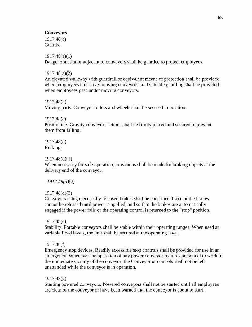
65
Conveyors
1917.48(a)
Guards.
1917.48(a)(1)
Danger zones at or adjacent to conveyors shall be guarded to protect employees.
1917.48(a)(2)
An elevated walkway with guardrail or equivalent means of protection shall be provided
where employees cross over moving conveyors, and suitable guarding shall be provided
when employees pass under moving conveyors.
1917.48(b)
Moving parts. Conveyor rollers and wheels shall be secured in position.
1917.48(c)
Positioning. Gravity conveyor sections shall be firmly placed and secured to prevent
them from falling.
1917.48(d)
Braking.
1917.48(d)(1)
When necessary for safe operation, provisions shall be made for braking objects at the
delivery end of the conveyor.
..1917.48(d)(2)
1917.48(d)(2)
Conveyors using electrically released brakes shall be constructed so that the brakes
cannot be released until power is applied, and so that the brakes are automatically
engaged if the power fails or the operating control is returned to the "stop" position.
1917.48(e)
Stability. Portable conveyors shall be stable within their operating ranges. When used at
variable fixed levels, the unit shall be secured at the operating level.
1917.48(f)
Emergency stop devices. Readily accessible stop controls shall be provided for use in an
emergency. Whenever the operation of any power conveyor requires personnel to work in
the immediate vicinity of the conveyor, the Conveyor or controls shall not be left
unattended while the conveyor is in operation.
1917.48(g)
Starting powered conveyors. Powered conveyors shall not be started until all employees
are clear of the conveyor or have been warned that the conveyor is about to start.

66
1917.48(h)
Loading and unloading. The area around conveyor loading and unloading points shall be
kept clear of obstructions during conveyor operations.
1917.48(i)
Lockout/Tagout.
1917.48(i)(1)
Conveyors shall be stopped and their power sources locked out and tagged out during
maintenance, repair, and servicing, unless power is necessary for testing.
..1917.48(i)(2)
1917.48(i)(2)
The starting device shall be locked out and tagged out in the stop position before an
attempt is made to remove the cause of a jam or overload of the conveying medium,
unless it is necessary to have the power on to remove the jam.
1917.48(j)
Safe practices.
1917.48(j)(1)
Only designated persons shall operate, repair or service powered conveyors.
1917.48(j)(2)
The employer shall direct employees to stay off operating conveyors.
1917.48(j)(3)
Conveyors shall be operated only with all overload devices, guards and safety devices in
place and operable.
[62 FR 40141, July 25, 1997]

67
Power Transmission
1910.219(a)
General requirements.
1910.219(a)(1)
This section covers all types and shapes of power-transmission belts, except the
following when operating at two hundred and fifty (250) feet per minute or less:
1910.219(a)(1)(i)
Flat belts one (1) inch or less in width,
1910.219(a)(1)(ii)
Flat belts two (2) inches or less in width which are free from metal lacings or fasteners,
1910.219(a)(1)(iii)
Round belts one-half (1/2) inch or less in diameter; and
1910.219(a)(1)(iv)
Single strand V-belts, the width of which is thirteen thirty-seconds (13/32) inch or less.
1910.219(a)(2)
Vertical and inclined belts (paragraphs (e) (3) and (4) of this section) if not more than two
and one-half (2 1/2) inches wide and running at a speed of less than one thousand (1,000)
feet per minute, and if free from metal lacings or fastenings may be guarded with a nip-
point belt and pulley guard.
..1910.219(a)(3)
1910.219(a)(3)
For the Textile Industry, because of the presence of excessive deposits of lint, which
constitute a serious fire hazard, the sides and face sections only of nip-point belt and
pulley guards are required, provided the guard shall extend at least six (6) inches beyond
the rim of the pulley on the in-running and off-running sides of the belt and at least two
(2) inches away from the rim and face of the pulley in all other directions.
1910.219(a)(4)
This section covers the principal features with which power transmission safeguards shall
comply.
1910.219(b)
Prime-mover guards –
1910.219(b)(1)
Flywheels. Flywheels located so that any part is seven (7) feet or less above floor or
platform shall be guarded in accordance with the requirements of this subparagraph:

68
1910.219(b)(1)(i)
With an enclosure of sheet, perforated, or expanded metal, or woven wire;
1910.219(b)(1)(ii)
With guard rails placed not less than fifteen (15) inches nor more than twenty (20) inches
from rim. When flywheel extends into pit or is within 12 inches of floor, a standard
toeboard shall also be provided;
1910.219(b)(1)(iii)
When the upper rim of flywheel protrudes through a working floor, it shall be entirely
enclosed or surrounded by a guardrail and toeboard.
..1910.219(b)(1)(iv)
1910.219(b)(1)(iv)
For flywheels with smooth rims five (5) feet or less in diameter, where the preceding
methods cannot be applied, the following may be used: A disk attached to the flywheel in
such manner as to cover the spokes of the wheel on the exposed side and present a
smooth surface and edge, at the same time providing means for periodic inspection. An
open space, not exceeding four (4) inches in width, may be left between the outside edge
of the disk and the rim of the wheel if desired, to facilitate turning the wheel over. Where
a disk is used, the keys or other dangerous projections not covered by disk shall be cut off
or covered. This subdivision does not apply to flywheels with solid web centers.
1910.219(b)(1)(v)
Adjustable guard to be used for starting engine or for running adjustment may be
provided at the flywheel of gas or oil engines. A slot opening for jack bar will be
permitted.
1910.219(b)(1)(vi)
Wherever flywheels are above working areas, guards shall be installed having sufficient
strength to hold the weight of the flywheel in the event of a shaft or wheel mounting
failure.
1910.219(b)(2)
Cranks and connecting rods. Cranks and connecting rods, when exposed to contact, shall
be guarded in accordance with paragraphs (m) and (n) of this section, or by a guardrail as
described in paragraph (o)(5) of this section.
1910.219(b)(3)
Tail rods or extension piston rods. Tail rods or extension piston rods shall be guarded in
accordance with paragraphs (m) and (o) of this section, or by a guardrail on sides and
end, with a clearance of not less than fifteen (15) nor more than twenty (20) inches when
rod is fully extended.

69
..1910.219(c)
1910.219(c)
Shafting –
1910.219(c)(1)
Installation.
1910.219(c)(1)(i)
Each continuous line of shafting shall be secured in position against excessive endwise
movement.
1910.219(c)(1)(ii)
Inclined and vertical shafts, particularly inclined idler shafts, shall be securely held in
position against endwise thrust.
1910.219(c)(2)
Guarding horizontal shafting.
1910.219(c)(2)(i)
All exposed parts of horizontal shafting seven (7) feet or less from floor or working
platform, excepting runways used exclusively for oiling, or running adjustments, shall be
protected by a stationary casing enclosing shafting completely or by a trough enclosing
sides and top or sides and bottom of shafting as location requires.
1910.219(c)(2)(ii)
Shafting under bench machines shall be enclosed by a stationary casing, or by a trough at
sides and top or sides and bottom, as location requires. The sides of the trough shall come
within at least six (6) inches of the underside of table, or if shafting is located near floor
within six (6) inches of floor. In every case the sides of trough shall extend at least two
(2) inches beyond the shafting or protuberance.
..1910.219(c)(3)
1910.219(c)(3)
Guarding vertical and inclined shafting. Vertical and inclined shafting seven (7) feet or
less from floor or working platform, excepting maintenance runways, shall be enclosed
with a stationary casing in accordance with requirements of paragraphs (m) and (o) of
this section.
1910.219(c)(4)
Projecting shaft ends.
1910.219(c)(4)(i)
Projecting shaft ends shall present a smooth edge and end and shall not project more than
one-half the diameter of the shaft unless guarded by nonrotating caps or safety sleeves.

70
1910.219(c)(4)(ii)
Unused keyways shall be filled up or covered.
1910.219(c)(5)
Power-transmission apparatus located in basements. All mechanical power transmission
apparatus located in basements, towers, and rooms used exclusively for power
transmission equipment shall be guarded in accordance with this section, except that the
requirements for safeguarding belts, pulleys, and shafting need not be complied with
when the following requirements are met:
1910.219(c)(5)(i)
The basement, tower, or room occupied by transmission equipment is locked against
unauthorized entrance.
1910.219(c)(5)(ii)
The vertical clearance in passageways between the floor and power transmission beams,
ceiling, or any other objects, is not less than five feet six inches (5 ft. 6 in.).
..1910.219(c)(5)(iii)
1910.219(c)(5)(iii)
The intensity of illumination conforms to the requirements of ANSI A11.1-1965 (R-
1970), which is incorporated by reference as specified in Sec. 1910.6.
1910.219(c)(5)(iv)
[Reserved]
1910.219(c)(5)(v)
The route followed by the oiler is protected in such manner as to prevent accident.
1910.219(d)
Pulleys –
1910.219(d)(1)
Guarding. Pulleys, any parts of which are seven (7) feet or less from the floor or working
platform, shall be guarded in accordance with the standards specified in paragraphs (m)
and (o) of this section. Pulleys serving as balance wheels (e.g., punch presses) on which
the point of contact between belt and pulley is more than six feet six inches (6 ft. 6 in.)
from the floor or platform may be guarded with a disk covering the spokes.
1910.219(d)(2)
Location of pulleys.

71
1910.219(d)(2)(i)
Unless the distance to the nearest fixed pulley, clutch, or hanger exceeds the width of the
belt used, a guide shall be provided to prevent the belt from leaving the pulley on the side
where insufficient clearance exists.
1910.219(d)(2)(ii)
[Reserved]
..1910.219(d)(3)
1910.219(d)(3)
Broken pulleys. Pulleys with cracks, or pieces broken out of rims, shall not be used.
1910.219(d)(4)
Pulley speeds. Pulleys intended to operate at rim speed in excess of manufacturers normal
recommendations shall be specially designed and carefully balanced for the speed at
which they are to operate.
1910.219(e)
Belt, rope, and chain drives –
1910.219(e)(1)
Horizontal belts and ropes.
1910.219(e)(1)(i)
Where both runs of horizontal belts are seven (7) feet or less from the floor level, the
guard shall extend to at least fifteen (15) inches above the belt or to a standard height,
except that where both runs of a horizontal belt are 42 inches or less from the floor, the
belt shall be fully enclosed in accordance with paragraphs (m) and (o) of this section.
1910.219(e)(1)(ii)
In powerplants or power-development rooms, a guardrail may be used in lieu of the guard
required by subdivision (i) of this subparagraph.
..1910.219(e)(2)
1910.219(e)(2)
Overhead horizontal belts.
1910.219(e)(2)(i)
Overhead horizontal belts, with lower parts seven (7) feet or less from the floor or
platform, shall be guarded on sides and bottom in accordance with paragraph (o)(3) of
this section.

72
1910.219(e)(2)(ii)
Horizontal overhead belts more than seven (7) feet above floor or platform shall be
guarded for their entire length under the following conditions:
1910.219(e)(2)(ii)(a)
If located over passageways or work places and traveling 1,800 feet or more per minute.
1910.219(e)(2)(ii)(b)
If center to center distance between pulleys is ten (10) feet or more.
1910.219(e)(2)(ii)(c)
If belt is eight (8) inches or more in width.
1910.219(e)(2)(iii)
Where the upper and lower runs of horizontal belts are so located that passage of persons
between them would be possible, the passage shall be either:
1910.219(e)(2)(iii)(a)
Completely barred by a guardrail or other barrier in accordance with paragraphs (m) and
(o) of this section; or
..1910.219(e)(2)(iii)(b)
1910.219(e)(2)(iii)(b)
Where passage is regarded as necessary, there shall be a platform over the lower run
guarded on either side by a railing completely filled in with wire mesh or other filler, or
by a solid barrier. The upper run shall be so guarded as to prevent contact therewith either
by the worker or by objects carried by him. In powerplants only the lower run of the belt
need be guarded.
1910.219(e)(2)(iv)
Overhead chain and link belt drives are governed by the same rules as overhead
horizontal belts and shall be guarded in the same manner as belts.
1910.219(e)(3)
Vertical and inclined belts.
1910.219(e)(3)(i)
Vertical and inclined belts shall be enclosed by a guard conforming to standards in
paragraphs (m) and (o) of this section.
1910.219(e)(3)(ii)
All guards for inclined belts shall be arranged in such a manner that a minimum clearance
of seven (7) feet is maintained between belt and floor at any point outside of guard.

73
1910.219(e)(4)
Vertical belts. Vertical belts running over a lower pulley more than seven (7) feet above
floor or platform shall be guarded at the bottom in the same manner as horizontal
overhead belts, if conditions are as stated in paragraphs (e)(2)(ii) (a) and (c) of this
section.
..1910.219(e)(5)
1910.219(e)(5)
Cone-pulley belts.
1910.219(e)(5)(i)
The cone belt and pulley shall be equipped with a belt shifter so constructed as to
adequately guard the nip point of the belt and pulley. If the frame of the belt shifter does
not adequately guard the nip point of the belt and pulley, the nip point shall be further
protected by means of a vertical guard placed in front of the pulley and extending at least
to the top of the largest step of the cone.
1910.219(e)(5)(ii)
If the belt is of the endless type or laced with rawhide laces, and a belt shifter is not
desired, the belt will be considered guarded if the nip point of the belt and pulley is
protected by a nip point guard located in front of the cone extending at least to the top of
the largest step of the cone, and formed to show the contour of the cone in order to give
the nip point of the belt and pulley the maximum protection.
1910.219(e)(5)(iii)
If the cone is located less than 3 feet from the floor or working platform, the cone pulley
and belt shall be guarded to a height of 3 feet regardless of whether the belt is endless or
laced with rawhide.
1910.219(e)(6)
Belt tighteners.
1910.219(e)(6)(i)
Suspended counterbalanced tighteners and all parts thereof shall be of substantial
construction and securely fastened; the bearings shall be securely capped. Means must be
provided to prevent tightener from falling, in case the belt breaks.
1910.219(e)(6)(ii)
Where suspended counterweights are used and not guarded by location, they shall be so
encased as to prevent accident.
..1910.219(f)
1910.219(f)
Gears, sprockets, and chains –

74
1910.219(f)(1)
Gears. Gears shall be guarded in accordance with one of the following methods:
1910.219(f)(1)(i)
By a complete enclosure; or
1910.219(f)(1)(ii)
By a standard guard as described in paragraph (o) of this section, at least seven (7) feet
high extending six (6) inches above the mesh point of the gears; or
1910.219(f)(1)(iii)
By a band guard covering the face of gear and having flanges extended inward beyond
the root of the teeth on the exposed side or sides. Where any portion of the train of gears
guarded by a band guard is less than six (6) feet from the floor a disk guard or a complete
enclosure to the height of six (6) feet shall be required.
1910.219(f)(2)
Hand-operated gears. Paragraph (f)(1) of this section does not apply to hand-operated
gears used only to adjust machine parts and which do not continue to move after hand
power is removed. However, the guarding of these gears is highly recommended.
1910.219(f)(3)
Sprockets and chains. All sprocket wheels and chains shall be enclosed unless they are
more than seven (7) feet above the floor or platform. Where the drive extends over other
machine or working areas, protection against falling shall be provided. This subparagraph
does not apply to manually operated sprockets.
..1910.219(f)(4)
1910.219(f)(4)
Openings for oiling. When frequent oiling must be done, openings with hinged or sliding
self-closing covers shall be provided. All points not readily accessible shall have oil feed
tubes if lubricant is to be added while machinery is in motion.
1910.219(g)
Guarding friction drives. The driving point of all friction drives when exposed to contact
shall be guarded, all arm or spoke friction drives and all web friction drives with holes in
the web shall be entirely enclosed, and all projecting belts on friction drives where
exposed to contact shall be guarded.
1910.219(h)
Keys, setscrews, and other projections.
1910.219(h)(1)
All projecting keys, setscrews, and other projections in revolving parts shall be removed
or made flush or guarded by metal cover. This subparagraph does not apply to keys or

75
setscrews within gear or sprocket casings or other enclosures, nor to keys, setscrews, or
oil cups in hubs of pulleys less than twenty (20) inches in diameter where they are within
the plane of the rim of the pulley.
1910.219(h)(2)
It is recommended, however, that no projecting setscrews or oil cups be used in any
revolving pulley or part of machinery.
1910.219(i)
Collars and couplings –
1910.219(i)(1)
Collars. All revolving collars, including split collars, shall be cylindrical, and screws or
bolts used in collars shall not project beyond the largest periphery of the collar.
..1910.219(i)(2)
1910.219(i)(2)
Couplings. Shaft couplings shall be so constructed as to present no hazard from bolts,
nuts, setscrews, or revolving surfaces. Bolts, nuts, and setscrews will, however, be
permitted where they are covered with safety sleeves or where they are used parallel with
the shafting and are countersunk or else do not extend beyond the flange of the coupling.
1910.219(j)
Bearings and facilities for oiling. All drip cups and pans shall be securely fastened.
1910.219(k)
Guarding of clutches, cutoff couplings, and clutch pulleys –
1910.219(k)(1)
Guards. Clutches, cutoff couplings, or clutch pulleys having projecting parts, where such
clutches are located seven (7) feet or less above the floor or working platform, shall be
enclosed by a stationary guard constructed in accordance with this section. A "U" type
guard is permissible.
1910.219(k)(2)
Engine rooms. In engine rooms a guardrail, preferably with toeboard, may be used
instead of the guard required by paragraph (k)(1) of this section, provided such a room is
occupied only by engine room attendants.
..1910.219(l)
1910.219(l)
Belt shifters, clutches, shippers, poles, perches, and fasteners –
1910.219(l)(1)
Belt shifters.

76
1910.219(l)(1)(i)
Tight and loose pulleys on all new installations made on or after August 31, 1971, shall
be equipped with a permanent belt shifter provided with mechanical means to prevent
belt from creeping from loose to tight pulley. It is recommended that old installations be
changed to conform to this rule.
1910.219(l)(1)(ii)
Belt shifter and clutch handles shall be rounded and be located as far as possible from
danger of accidental contact, but within easy reach of the operator. Where belt shifters are
not directly located over a machine or bench, the handles shall be cut off six feet six
inches (6 ft. 6 in.) above floor level.
1910.219(l)(2)
Belt shippers and shipper poles. The use of belt poles as substitutes for mechanical
shifters is not recommended.
1910.219(l)(3)
Belt perches. Where loose pulleys or idlers are not practicable, belt perches in form of
brackets, rollers, etc., shall be used to keep idle belts away from the shafts.
1910.219(l)(4)
Belt fasteners. Belts which of necessity must be shifted by hand and belts within seven
(7) feet of the floor or working platform which are not guarded in accordance with this
section shall not be fastened with metal in any case, nor with any other fastening which
by construction or wear will constitute an accident hazard.
..1910.219(m)
1910.219(m)
Standard guards-general requirements –
1910.219(m)(1)
Materials.
1910.219(m)(1)(i)
Standard conditions shall be secured by the use of the following materials. Expanded
metal, perforated or solid sheet metal, wire mesh on a frame of angle iron, or iron pipe
securely fastened to floor or to frame of machine.
1910.219(m)(1)(ii)
All metal should be free from burrs and sharp edges.
1910.219(m)(2)
Methods of manufacture.

77
1910.219(m)(2)(i)
Expanded metal, sheet or perforated metal, and wire mesh shall be securely fastened to
frame.
1910.219(n)
[Reserved]
1910.219(o)
Approved materials –
1910.219(o)(1)
Minimum requirements. The materials and dimensions specified in this paragraph shall
apply to all guards, except horizontal overhead belts, rope, cable, or chain guards more
than seven (7) feet above floor, or platform.
1910.219(o)(1)(i)
[Reserved]
1910.219(o)(1)(i)(a)
All guards shall be rigidly braced every three (3) feet or fractional part of their height to
some fixed part of machinery or building structure. Where guard is exposed to contact
with moving equipment additional strength may be necessary.
..1910.219(o)(2)
1910.219(o)(2)
Wood guards.
1910.219(o)(2)(i)
Wood guards may be used in the woodworking and chemical industries, in industries
where the presence of fumes or where manufacturing conditions would cause the rapid
deterioration of metal guards; also in construction work and in locations outdoors where
extreme cold or extreme heat make metal guards and railings undesirable. In all other
industries, wood guards shall not be used.
1910.219(o)(3)
Guards for horizontal overhead belts.
1910.219(o)(3)(i)
Guards for horizontal overhead belts shall run the entire length of the belt and follow the
line of the pulley to the ceiling or be carried to the nearest wall, thus enclosing the belt
effectively. Where belts are so located as to make it impracticable to carry the guard to
wall or ceiling, construction of guard shall be such as to enclose completely the top and
bottom runs of belt and the face of pulleys.

78
1910.219(o)(3)(ii)
[Reserved]
..1910.219(o)(3)(iii)
1910.219(o)(3)(iii)
Suitable reinforcement shall be provided for the ceiling rafters or overhead floor beams,
where such is necessary, to sustain safely the weight and stress likely to be imposed by
the guard. The interior surface of all guards, by which is meant the surface of the guard
with which a belt will come in contact, shall be smooth and free from all projections of
any character, except where construction demands it; protruding shallow roundhead
rivets may be used. Overhead belt guards shall be at least one-quarter wider than belt
which they protect, except that this clearance need not in any case exceed six (6) inches
on each side. Overhead rope drive and block and roller-chain-drive guards shall be not
less than six (6) inches wider than the drive on each side. In overhead silent chain-drive
guards where the chain is held from lateral displacement on the sprockets, the side
clearances required on drives of twenty (20) inch centers or under shall be not less than
one-fourth inch from the nearest moving chain part, and on drives of over twenty (20)
inch centers a minimum of one-half inch from the nearest moving chain part.
1910.219(o)(4)
Guards for horizontal overhead rope and chain drives. Overhead-rope and chain-drive
guard construction shall conform to the rules for overhead-belt guard.
1910.219(o)(5)
Guardrails and toeboards.
1910.219(o)(5)(i)
Guardrail shall be forty-two (42) inches in height, with midrail between top rail and floor.
1910.219(o)(5)(ii)
Posts shall be not more than eight (8) feet apart; they are to be permanent and substantial,
smooth, and free from
protruding nails, bolts, and splinters. If made of pipe, the post shall be one and one-fourth
(1 1/4) inches inside diameter, or larger. If made of metal shapes or bars, their section
shall be equal in strength to that of one and one-half (1 1/2) by one and one-half (1 1/2)
by three-sixteenths (3/16) inch angle iron. If made of wood, the posts shall be two by four
(2 X 4) inches or larger. The upper rail shall be two by four (2 X 4) inches, or two one by
four (1 X 4) strips, one at the top and one at the side of posts. The midrail may be one by
four (1 X 4) inches or more. Where panels are fitted with expanded metal or wire mesh
the middle rails may be omitted. Where guard is exposed to contact with moving
equipment, additional strength may be necessary.
..1910.219(o)(5)(iii)

79
1910.219(o)(5)(iii)
Toeboards shall be four (4) inches or more in height, of wood, metal, or of metal grill not
exceeding one (1) inch mesh.
1910.219(p)
Care of equipment –
1910.219(p)(1)
General. All power-transmission equipment shall be inspected at intervals not exceeding
60 days and be kept in good working
condition at all times.
1910.219(p)(2)
Shafting.
1910.219(p)(2)(i)
Shafting shall be kept in alignment, free from rust and excess oil or grease.
1910.219(p)(2)(ii)
Where explosives, explosive dusts, flammable vapors or flammable liquids exist, the
hazard of static sparks from shafting
shall be carefully considered.
1910.219(p)(3)
Bearings. Bearings shall be kept in alignment and properly adjusted.
1910.219(p)(4)
Hangers. Hangers shall be inspected to make certain that all supporting bolts and screws
are tight and that supports of hanger boxes are adjusted properly.
1910.219(p)(5)
Pulleys.
1910.219(p)(5)(i)
Pulleys shall be kept in proper alignment to prevent belts from running off.
..1910.219(p)(6)
1910.219(p)(6)
Care of belts.
1910.219(p)(6)(i)
[Reserved]

80
1910.219(p)(6)(ii)
Inspection shall be made of belts, lacings, and fasteners and such equipment kept in good
repair.
1910.219(p)(7)
Lubrication. The regular oilers shall wear tight-fitting clothing. Machinery shall be oiled
when not in motion, wherever possible.
[39 FR 23502, June 27, 1974, as amended at 43 FR 49750, Oct. 24, 1978; 43 FR 51760;
Nov. 7, 1978; 49 FR 5323, Feb. 10,
1984; 61 FR 9227, March 7, 1996; 69 FR 31882, June 8, 2004]

81
APPENDIX F – Material Cut Sheet

82

83
APPENDIX G – SolidWorks Part Drawings

84

85
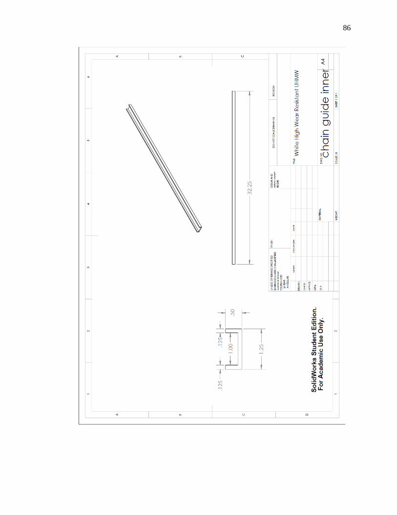
86
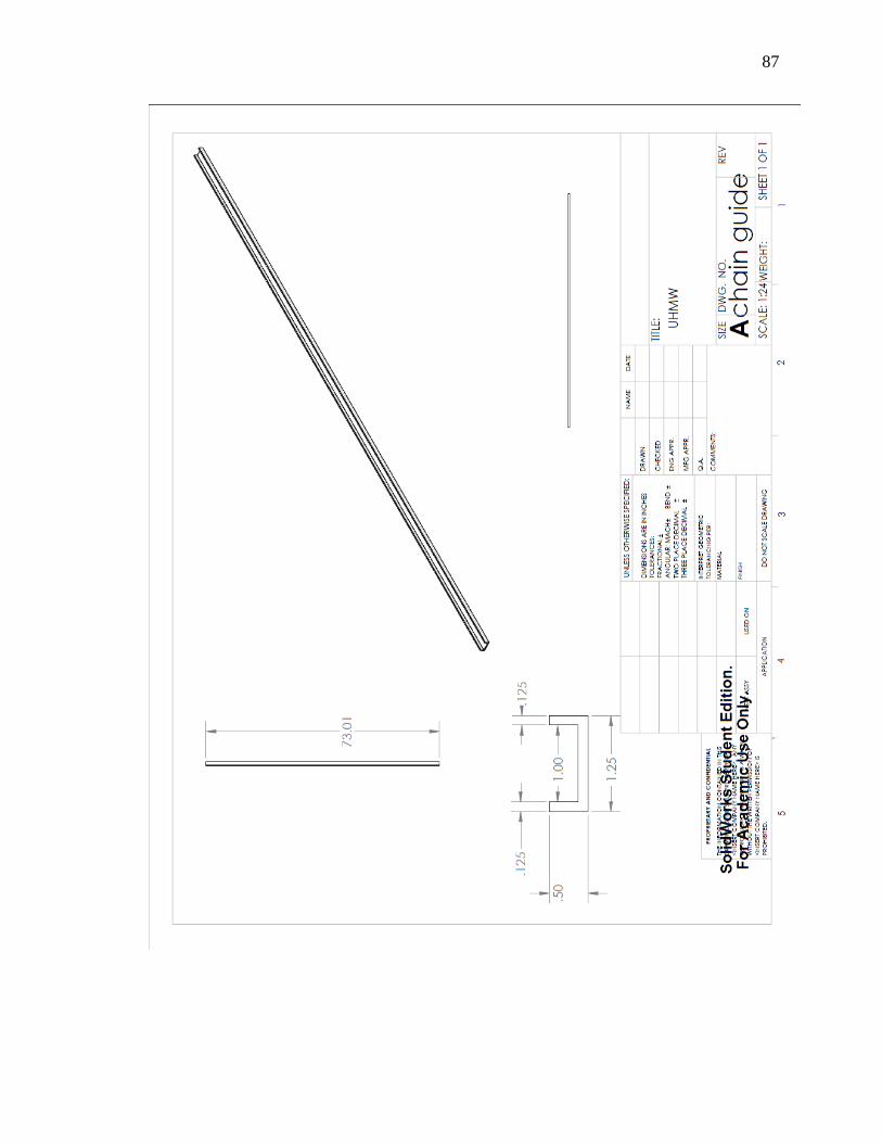
87

88
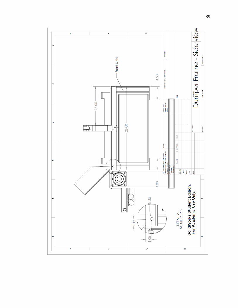
89

90

91

92

93

94

95

96

97

98

99

100

101
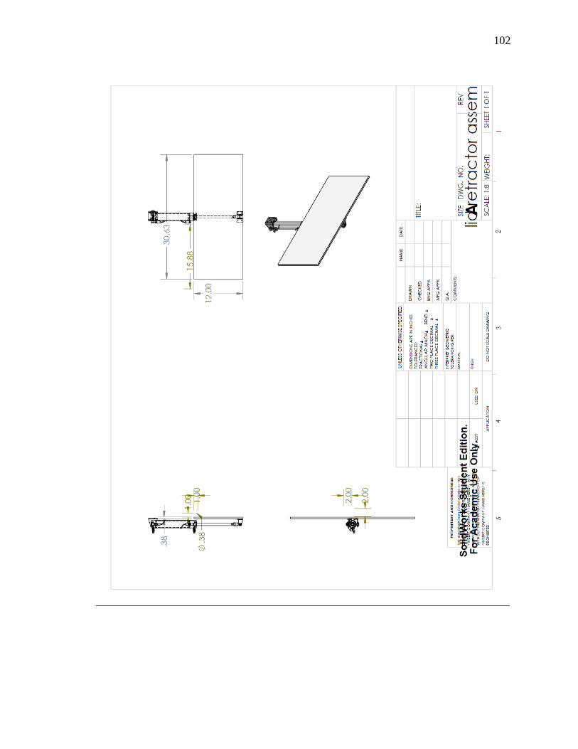
102
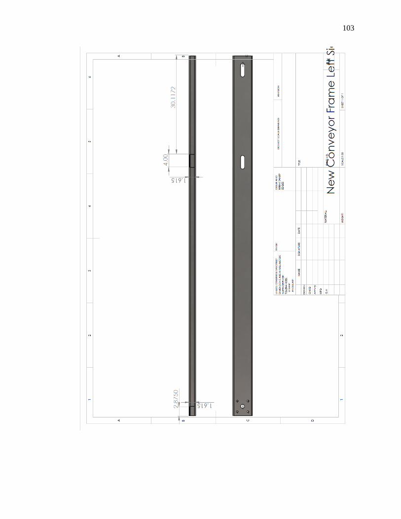
103

104

105
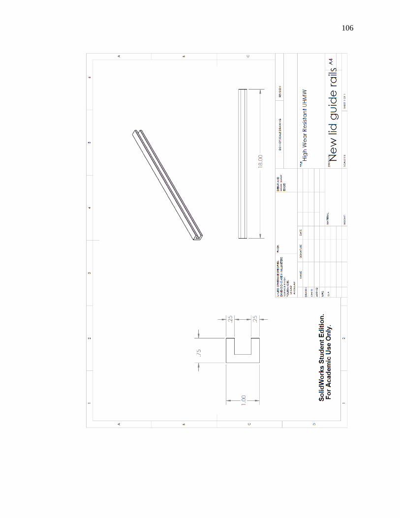
106
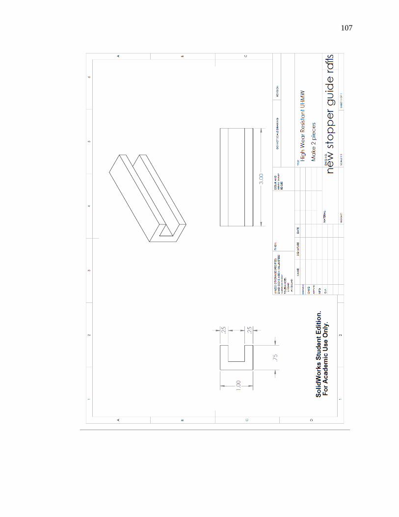
107

108

109

110

111

112

113

114

115

116

117

118

119

120

121

122

123