Embed Size (px)
Citation preview

Institute for Thermal Turbomaschinery and Machine Dynamics
Graz University of TechnologyErzherzog-Johann-University
Design Concept for Large Output Graz Cycle Gas Turbines
Presentation at the ASME Turbo Expo 2006
Barcelona, Spain, May 8 - 11, 2006
Herbert Jericha, Wolfgang Sanz and Emil Göttlich Institute for Thermal Turbomachinery and Machine Dynamics
Graz University of TechnologyAustria
Motivation
How do you want your egg(s)? - Sunny side up?But do not have it burned!
Background
• Toronto Conference 1988, a Call for Action• Kyoto Protocol demands the reduction of
greenhouse gases, mainly CO2• In EU: strong pressure on utilities and companies
to reduce CO2 emissions• In 2005: emission allowances to about 10 000
companies within the EU covering about 46 % of the overall EU CO2 emissions
• As emission allowances become scarce: CO2 generates costs (European Emission Allowances in March 2006: 27 €/ton CO2)
• CO2 and N2 from ASU can be utilized for Enhanced Oil Recovery (EOR)Return: 20 – 40 $/ton CO2

Oxy-Fuel Cycles
• Oxy-fuel cycles with internal combustion with pure oxygen are a very promising technology(Global Gas Turbine News 10/2005)
+ CO2 can be easily separated by condensation fromworking fluid consisting of CO2 and H2O, no need for very penalizing scrubbing
+ Very low NOx generation (fuel bound N2)
+ Flexibility regarding fuel: natural gas, syngas from coal, biomass or refinery residue gasification
- New equipment required
- Additional high costs of oxygen production
+ These new cycles show higher efficiencies than current air-based combined cycles (Graz Cycle,Matiant cycle, Water cycle,...)

History of the Graz Cycle
• 1985: presentation of a power cycle without any emission (CIMAC Oslo)• H2/O2 internally fired steam cycle, as integration of top Brayton
steam cycle and bottom Rankine cycle • efficiency 6 % - points higher than state-of-the art CC plants
• 1995: Graz cycle adopted for the combustion of fossil fuels like methane (CH4) (CIMAC Interlaken & ASME Cogen Vienna)• cycle fluid is a mixture of H2O and CO2• thermal cycle efficiency: 64 %
• 2000: thermodynamically optimized cycle for syngas from coal gasification (VDI Essen)
• 2002/2003: conceptual layout of prototype Graz Cycle power plant: detailed design of components (ASME Amsterdam, VDI Leverkusen, ASME Atlanta)
• 2004/2005: presentation of S-Graz Cycle with 69% thermal efficiency and 57 % net efficiency for syngas firing (ASME Vienna, ASME Reno)

Graz Cycle Basic Configuration (ASME 04/05)
H2O
CO2CO2
C3/C4
Cond. P.water
Feed Pump180 bar565°C
HPTDeaerator
HTT High Temperature Turbine
HRSG Heat Recovery Steam Gen.
LPT Low Pressure Turbine
C3/C4 CO2 Compressors
C1/C2 Cycle Fluid Compressors
HPT High Pressure Turbine
0.04 bar
LPT Condenser
C1/C2
600°C
Cycle Fluid
77 % H2O23 % CO2
HTT1400°C
HRSG
1bar573°C
water injectionfor cooling
Fuel(methane)
O2Combustor
steam
40 bar
Power Balance ASME 2005
• Electrical cycle efficiency for methane firing:Efficiency: 64.6 % (same for syngas firing)
• Oxygen production (0.15 - 0.3): 0.25 kWh/kg Oxygen compression (2.38 to 40 bar, inter-cooled): 325 kJ/kg Efficiency: 54.8 %
• Compression of separated CO2 for liquefaction (1 to 100 bar, inter-cooled): 270 kJ/kg (3.7 MW)Efficiency: 52.7 %

Condensation/Re-Vaporization at around 1 bar
Cycle Fluid
79 % H2O21 % CO2
H2O
CO2
water
C4
1.95 bar
C3
1.27 bar
0.75 bar
LPST Condenser
175 °C 0.021 bar180 bar550°C
HPT
Deaerator
C1/C2
580°C
Fuel(methane)
O2Combustor
steam
40 bar
HTT1400°C
HRSG
1bar573°C
180°C
water injectionfor cooling
Compressors C3 and C4 raisepartial steam pressure for condensation and deliver CO2
Heat Transfer in Condenser/Evaporator
0
50
100
150
200
0 20000 40000 60000 80000
Heat [kW]
Tem
pera
ture
[°C
]
Condenser/Evaporator 1
Preheater1+2
Condenser/Evaporator 2
water/steam
working fluid
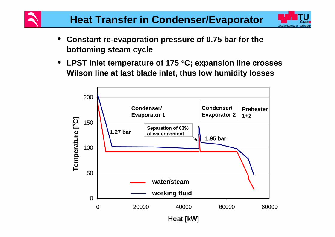
1.27 bar1.95 bar
Separation of 63% of water content
• Constant re-evaporation pressure of 0.75 bar for the bottoming steam cycle
• LPST inlet temperature of 175 °C; expansion line crosses Wilson line at last blade inlet, thus low humidity losses

S-Graz Cycle Power Balance for 400 MW net power
64.6Electrical cycle efficiency [%]
66.5Thermal cycle efficiency [%]
759Total heat input [MW]
505Net shaft power [MW]
235 Total compression power [MW]
739Total turbine power [MW]
638HTT power [MW]
New LayoutBasic Layout
635
64.6
66.5
759
504
249
753

Additional Losses and Expenses
• Oxygen production: 0.25 kWh/kg = 900 kJ/kg Oxygen compression (2.38 to 42 bar, inter-cooled): 325 kJ/kg
Efficiency: 54.8 %
• Compression of separated CO2 for liquefaction (1.9 to 100 bar): 13 MW (1 to 100 bar: 15.6 MW)
Efficiency: 53.1 % (compared to 52.7 %)

490 MW Turbo Shaft Configuration
• Main gas turbine components on two shafts for 400 MW net output• Compression shaft of 8500 rpm: cycle compressors C1 and C2, driven
by first part of HTT, the compressor turbine HTTC• Power shaft of 3000/3600 rpm: power turbine HTTP as second part of
HTT drives the generatorFour-flow LPST at the opposite side of the generator
• Shafts on same spring foundationIntercooler between C1 and C2 on fixed foundation connected to HRSG
Side view
Vertical section
Inter-cooler
From HRSG
To HRSG
Generator
4-flow 3-stage LPST
From Condenser/Evaporator
C2C1
High Speed Shaft Low Speed Shaft
HTT
Spring supported foundation plate

Working Fluid Compressor C1
• Compression 1 -> 13 bar, 106° -> 442°C • Speed of 8500 rpm leads to inlet tip Mach number of 1.3• 7 axial and 1 radial stage, 8500 rpm • Uncooled drum rotor of ferritic steel (high temperature 9 %-chrome steel)
Vaneless radial diffuser
Exit scroll
Radial stage from Nickel alloy
To Intercooler

Working Fluid Compressor C2
• Compression 13 -> 40 bar, 380° -> 580°C , 7 stages, 8500 rpm• Cooled drum rotor of ferritic steel with counterflow of cooling steam• Blade length of 90 to 40 mm, small radial tip clearances
Cooling steam
Combustor
C1
From Intercooler
Inlet scroll
Steam injectionfor meridionalflow improvement
Intercooler between C1 and C2
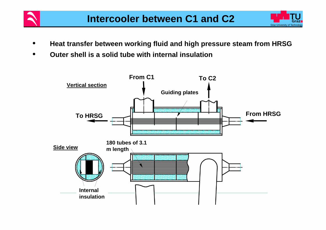
• Heat transfer between working fluid and high pressure steam from HRSG • Outer shell is a solid tube with internal insulation
Side view
Vertical sectionFrom C1 To C2
180 tubes of 3.1 m length
From HRSGTo HRSG
Guiding plates
Internal insulation
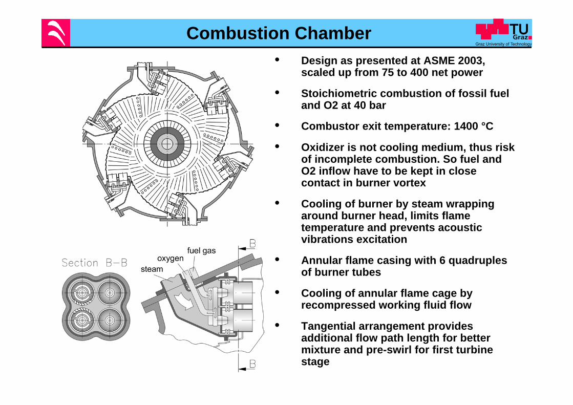
Combustion Chamber• Design as presented at ASME 2003,
scaled up from 75 to 400 net power
• Stoichiometric combustion of fossil fuel and O2 at 40 bar
• Combustor exit temperature: 1400 °C
• Oxidizer is not cooling medium, thus risk of incomplete combustion. So fuel and O2 inflow have to be kept in close contact in burner vortex
• Cooling of burner by steam wrapping around burner head, limits flame temperature and prevents acoustic vibrations excitation
• Annular flame casing with 6 quadruples of burner tubes
• Cooling of annular flame cage by recompressed working fluid flow
• Tangential arrangement provides additional flow path length for better mixture and pre-swirl for first turbine stage

Compressor Turbine HTTC for 50 Hz
• HTTC: reaction turbine with 2 subsonic stages and blade length of 100 mm and 164 mm
• Rotor cooling steam along the drum surface• Nozzles and blades are cooled in conventional serpentine passage
design with holes
Compressor Turbine HTTC
Power Turbine HTTP
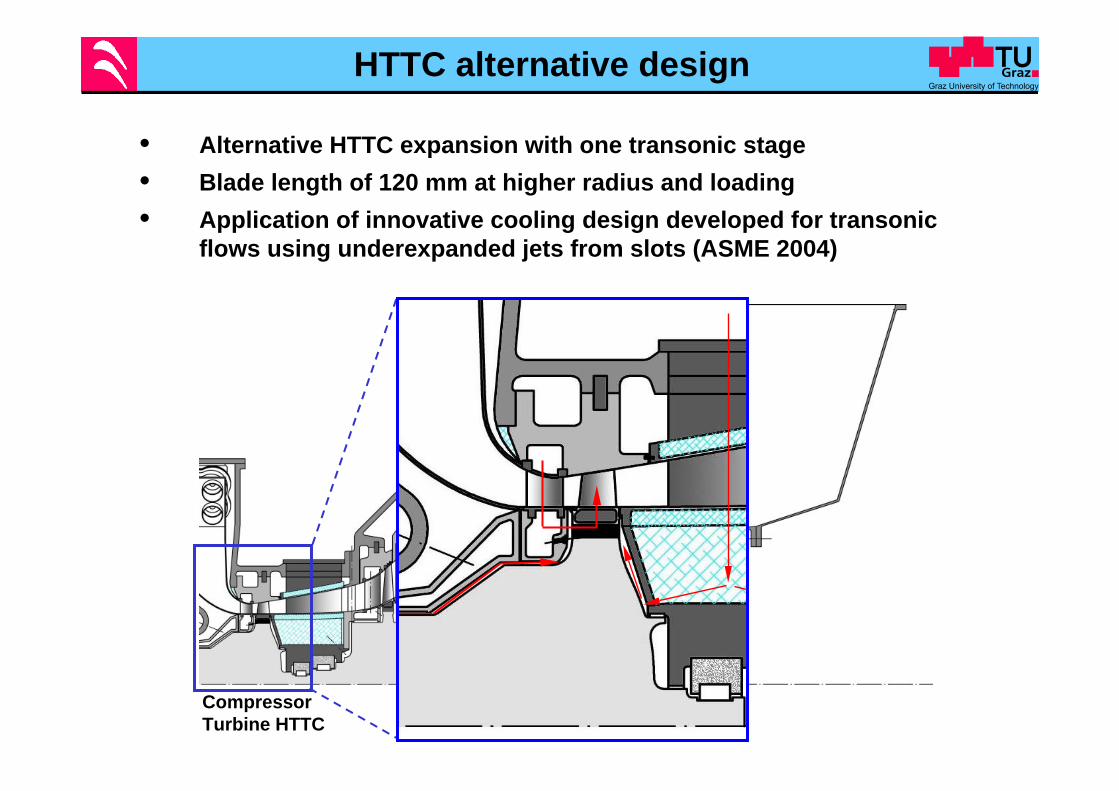
HTTC alternative design
• Alternative HTTC expansion with one transonic stage• Blade length of 120 mm at higher radius and loading• Application of innovative cooling design developed for transonic
flows using underexpanded jets from slots (ASME 2004)
Compressor Turbine HTTC
Power Turbine HTTP

Rotor cooling
Thrust equalizationand drum cooling
1st and 2nd stage cooling
Power Turbine HTTP for 50 Hz
• 5 stages with strong change of inner radius• Last blade length of 750 mm at 1300 mm inner radius• Internal insulation of intermediate bearing casing, design similar to HP
steam turbine presented at ASME 1988, Amsterdam • Necessary thrust equalization and drum surface cooling on the
exhaust side by steam

Power Turbine HTTP for 60 Hz
• 4 stages with strong change of inner radius• Last blade length of 600 mm at 1300 mm inner radius• HTTC outlet and HTTP inlet at the same radius
Rotor cooling
Thrustequalization and drum cooling
1st and 2nd stage cooling

Comparison of turbo set 50 - 60 Hz
50 Hz: two-stage subsonic HTTC
60 Hz: one-stage transonic HTTC
9.2 m
9.8 m

Low Pressure Steam Turbine
• Inlet: 0.75 bar and 175°C • Condensation pressure of 0.021 bar leads to a high volume flow• At 50 Hz a four-flow design with three stages• Transonic last stage with a blade length of 970 mm• Expansion line crosses Wilson line at last stage inlet; thus formation
of small droplets only in the exhaust
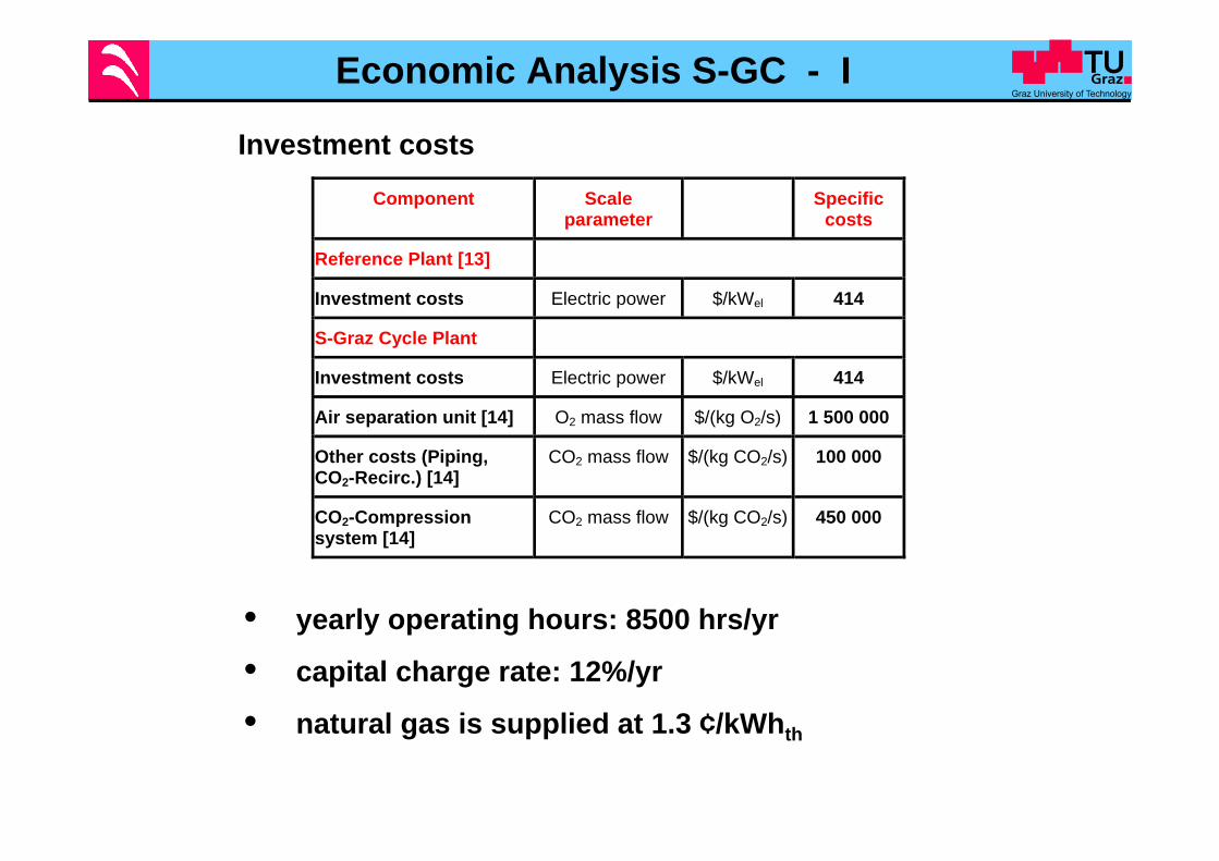
Economic Analysis S-GC - I
Component Scaleparameter
Specificcosts
Reference Plant [13]
Investment costs Electric power $/kWel 414
S-Graz Cycle Plant
Investment costs Electric power $/kWel 414
Air separation unit [14] O2 mass flow $/(kg O2/s) 1 500 000
Other costs (Piping,CO2-Recirc.) [14]
CO2 mass flow $/(kg CO2/s) 100 000
CO2-Compressionsystem [14]
CO2 mass flow $/(kg CO2/s) 450 000
• yearly operating hours: 8500 hrs/yr
• capital charge rate: 12%/yr
• natural gas is supplied at 1.3 ¢/kWhth
Investment costs
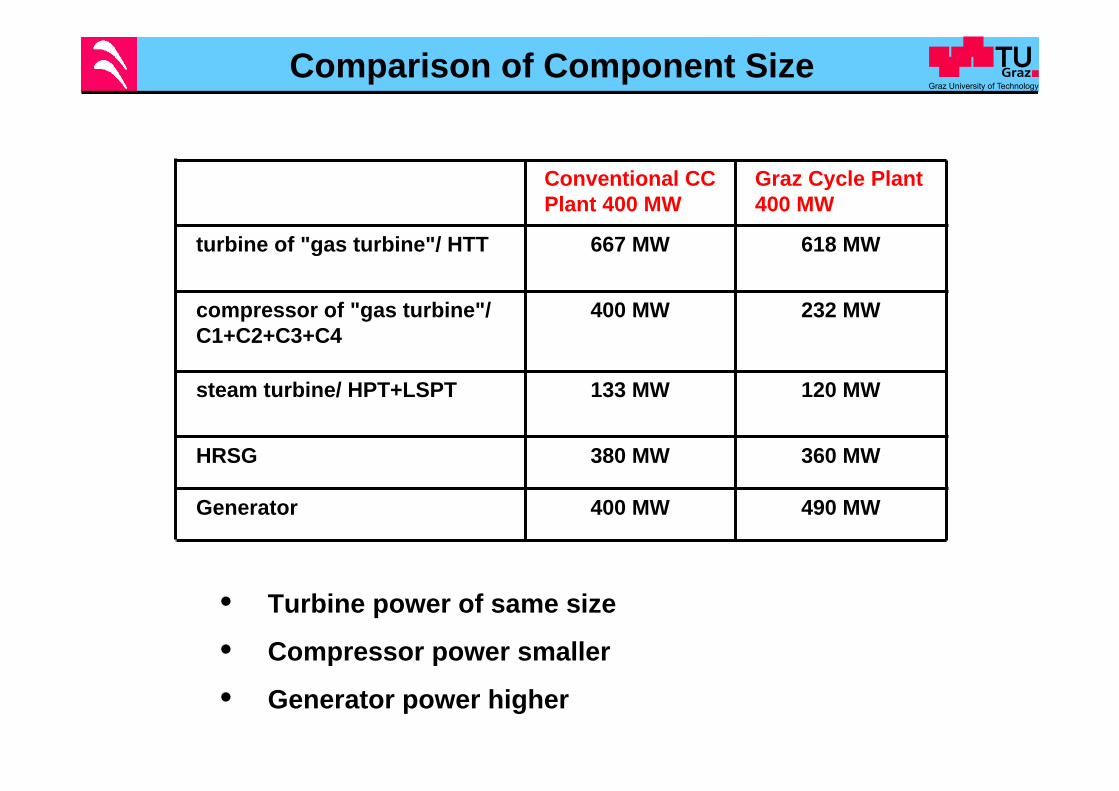
Comparison of Component Size
• Turbine power of same size
• Compressor power smaller
• Generator power higher
Conventional CC Plant 400 MW
Graz Cycle Plant 400 MW
turbine of "gas turbine"/ HTT 667 MW 618 MW
compressor of "gas turbine"/ C1+C2+C3+C4
400 MW 232 MW
steam turbine/ HPT+LSPT 133 MW 120 MW
HRSG 380 MW 360 MW
Generator 400 MW 490 MW

Economical Analysis S-GC - II
COE ...
Cost of Electricity
Reference plant [23]
S-GC new version
Plant capital costs [$/kWel] 414 414
Addit. capital costs [$/kWel] 288
CO2 emitted [kg/kWhel] 0.342 0.0
Net plant efficiency [%] 58.0 53.1
COE for plant amort. [¢/kWhel] 0.58 0.99
COE due to fuel [¢/kWhel] 2.24 2.45
COE due to O&M [¢/kWhel] 0.7 0.8
Total COE [¢/kWhel] 3.52 4.24
Comparison
Differential COE [¢/kWhel] 0.72(+ 20 %)
Mitigation costs [$/ton CO2 capt.] 21.0

Influence of Capital Costs S-GC
Favorable assumption of Göttlicher (VDI): 70 % additional capital costs for air supply and CO2 compressionBut large uncertainty in cost estimation:e.g.: ASU: cost estimates differ between 230 and 400 $/kW_el
0
10
20
30
40
50
100 150 200 250 300
Capital Cost Ratio between S-GC and Ref. Plant [%]
Miti
gatio
n C
osts
[$/t
CO
2]
% % % % %
Reference Plant
Range of ASU costs
Conclusions
• Graz Cylce is an oxy-fuel power cycle of highest efficiency
• Modified cycle configuration with condensation in the range of 1bar with re-evaporation of pure steam to feed LPST results in a high net cycle efficiency above 53 %
• Output raised from industrial size of 75 MW to 400 MW net output
• A design concept for this size is presented with two shafts, a fast running compression shaft and the power shaft and LPST
• Economic comparison with reference plant shows the strong influence of capital costs on CO2 mitigation costs
• Mitigation costs vary between 20 - 30 $/ton CO2 depending on additional investment costs (ASU)
• Presentation of a design solution for an oxy-fuel CO2 retaining gas turbine system which can by acceptance of international gas turbine industry be put into operation within a few years