Embed Size (px)
Citation preview

1/35
Design Codes And Practical Applications of
Concrete-Filled Steel Tube (CFT) Structures
in Japanin Japan
22th/Jan./2015
Akihiko KAWANO
Kyushu UniversityKyushu University

2/35
Contents
Japanese laws and regulations, overview of the design guidelinesg
Concrete-filled steel tube structure design Guidelines of AIJ AIJ
Construction Statistics of CFT Buildings according to ANUHT-collected data ANUHT collected data
Recent CFT buildings in Japan
Summary

3/35
Japanese laws and regulations,p g ,overview of the design guidelines

4/35
Japanese laws and regulations, overview of the design guidelines
Structural design corresponds to laws and regulations in Japan
Figure 1 Flow of Japanese seismic design

5/35
Japanese laws and regulations, overview of the design guidelines
Overview of the design guidelines in Japan
MLIT (Ministry of Land Infrastructure and Transport) NotificationMLIT (Ministry of Land, Infrastructure and Transport) Notification
By the MLIT Notification No. 464 2002), CFT structure was observed as one of general structures in the building standards law. From then, CFT
structures were spread rapidly.
ANUHT (Association of new urban housing technology)guidelinesguidelines
ANUHT published "CFT structure technology standards and commentary with construction execution and design calculation
examples, etc." to supplement the MLIT Notification. The Chapter 2 is
the ANUHT Guidelines essentially.
AIJ (Architectural Institute of Japan ) guidelinesAIJ (Architectural Institute of Japan ) guidelines
The current Guidelines for Design and Construction of Concrete FilledSteel Tubular Structures was published at 2008. AIJ Guidelines are
revised approximately every 10 years since 1976.

6/35
Concrete-filled steel tube structure design Guidelines of AIJ
Comparison among AIJ guidelines, MLIT notification and
ANUHT guidelinesANUHT guidelines
Notification by MLIT is conservative enough. However, theexception is recognized.
Since ANUHT Guidelines are developed for high-rise buildings, it islimited to short columns and small width-to-thickness ratio.
AIJ Guidelines include slender columns and the larger width-to-AIJ Guidelines include slender columns and the larger width tothickness ratio, as long as the deformability is ensured
Table 2 Limitations and Regulations
Concrete
strength
Steel tube
yield strength
(N/mm2) (N/mm
2)
Confining effectD/t of
circular tube
D/t of
square tube
Length of
beam-column
g
(N/mm ) (N/mm )
Notification by
MLIT>=24
Circular &
Rectangular tubes<=50 <=34 l k /D <=12
AIJ< 90 < 440 Circ lar t be onl < 100* < 59* l /D < 30
Recommendations<=90 <=440 Circular tube only <=100* <=59* l k /D <=30
ANUHT
Recommendations<=90 <=440
Circular &
Rectangular tubes<=67 <=44 h 0/D <=6

7/35
Concrete-filled steel tube structure design Guidelines of AIJ
Ultimate axial strength of column
Ultimate M-N strength of columng
Ultimate strength of beam-to-column connection
8/35
Concrete-filled steel tube structure design Guidelines of AIJ
Ultimate axial strength of column
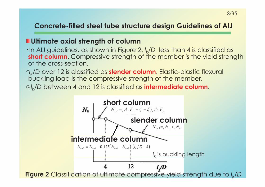
In AIJ guidelines as shown in Figure 2 lk/D less than 4 is classified as In AIJ guidelines, as shown in Figure 2, lk/D less than 4 is classified as short column. Compressive strength of the member is the yield strength of the cross-section.
G�l /D over 12 is classified as slender column Elastic-plastic flexural lk/D over 12 is classified as slender column. Elastic-plastic flexural buckling load is the compressive strength of the member.
G�lk/D between 4 and 12 is classified as intermediate column.
short columnyscccu FAFAN )1(1
slender columncrscrccu NNN 3
intermediate column4125.0 3112 DlNNNN kcucucucu
lk is buckling length k g g
Figure 2 Classification of ultimate compressive yield strength due to lk/D

9/35
Concrete-filled steel tube structure design Guidelines of AIJ
Ultimate axial strength of column (2)
(a) Ultimate compressive strength of short column N(a) Ultimate compressive strength of short column Ncu1
Calculation formula of Ncu1 (lk/D less than 4) is the following equation.
FAFAN )1(
is a factor to represent the confinement effect.
(Ci l CFT 0 27 S CFT 0)
yscccu FAFAN )1(1
(Circular CFT: =0.27, Square CFT: =0)
cA is the cross-sectional area of concrete
sA is the cross-sectional area of steel pipesA is the cross sectional area of steel pipe
Fc is the design strength of concrete
Fy is the yield strength of steel pipe

10/35
Concrete-filled steel tube structure design Guidelines of AIJ
Figure 3 The relationship of Ultimate compressive yield strength of circular CFT and Axial force share of steel pipeFigure 3 The relationship of Ultimate compressive yield strength of circular CFT and Axial force share of steel pipeFigure 3 The relationship of Ultimate compressive yield strength of circular CFT and Axial force share of steel pipe
Ultimate axial strength of column (3)
(a) Ultimate compressive strength of short column N (2)(a) Ultimate compressive strength of short column Ncu1 (2)
was determined to 0.27 by regression of the experimental data as shown in Figure 3.
When is 0.27, from Richart’s equation and von Mises yield criterion, the pipe hoop stress corresponds to -0.19ssy as shown in Figure 4.
compressivecompressive
tensile
Figure 3 Ultimate compressive strength
and Axial force component of steel pipe
Figure 4 Stress state of
yield condition of von Mises

11/35
Concrete-filled steel tube structure design Guidelines of AIJ
Ultimate axial strength of member (4)
(b)Ultimate tensile strength of member N(b)Ultimate tensile strength of member Ntu
Tensile strength Ntu is not related to the length of the column.Infill concrete has no resistance in tension.
By assuming the pipe hoop stress in circular CFT = -0.19s y, the pipe longitudinal tensile yield stress is 2 s y ( 2 =1.08)
In case of square CFT the Confinement effect is not In case of square CFT, the Confinement effect is not considered
FAN
From the above, the following formula is derived.
ystu FAN 2
2=-1.08 circular CFT =0 square CFT

12/35
Concrete-filled steel tube structure design Guidelines of AIJ
Ultimate axial strength of member (5)(c) Compressive strength of slender column N 3(c) Compressive strength of slender column Ncu3
NNN
Ncu3 is the superposed strength of cNcr (strength of concrete slender column) and sNcr (strength of steel pipe slender column) as follows:
crscrccu NNN 3
The cNcr and the sNcr are determined by the column curves in Fig 5 and 6, respectively.
AN ccrccrc
Recommendations for
the Plastic Design
and 6, respectively.
AN scrscrs
Allowable compressive stress for
sustained loading
Allowable compressive stress for
t l di
the Plastic Design
temporary loading
Figure 5 Column curve of concrete column Figure 6 column curve of steel pipe column

13/35
Concrete-filled steel tube structure design Guidelines of AIJ
Ultimate axial strength of member (6)(d) Compressive strength of intermediate column Ncu2(d) Co p ess e s e g o e ed a e co u cu2
The Ncu2 is linearly-interpolated between short column andslender column (When lk/DH�12) .
4125.0 3112 DlNNNN kcucucucu
short column
slender column
intermediate column
Figure 2

14/35
Concrete-filled steel tube structure design Guidelines of AIJ
Ultimate M-N strength of columnFollowing Equations indicate the superposed strength It corresponds Following Equations indicate the superposed strength. It corresponds to the static allowable state in plastic analysis.
In other words, the superposed strength need not satisfy compatibility in strains among steel and concrete However to compatibility in strains among steel and concrete. However, to satisfy the compatibility, the strength is maximized, and it is called as the generalized superposed strength.
usucu NNN
usucu
usucu
MMMN M are the bending moment and a ial force at the time of Nu, Mu are the bending moment and axial force at the time of
ultimate limit.
cNu, cMu are the axial force and bending moment will be resisted by
the concrete at the time of force ultimate limit the concrete at the time of force ultimate limit.
sNu, sMu are the axial force and bending moment will be resisted by
the steel pipe at the time of force ultimate limit.

15/35
Concrete-filled steel tube structure design Guidelines of AIJ
Ultimate M-N strength of column (2)
Ultimate M-N strength of short columngFigure 7 shows M-N strength of Steel pipe (S) and filling concrete (C),
generalized superposed strength (blue line) and simple superposed
strength (red line). strength (red line).
As for the simple superposed strength, concrete portion mainly supports the axial load and steel portion supports bending moment,
except that axial load is in tension or axial load is over the concrete except that axial load is in tension or axial load is over the concrete
compressive strength.
Figure 7 Superposed strength

16/35
Concrete-filled steel tube structure design Guidelines of AIJ
Ultimate M-N strength of column (3)
Ultimate M-N strength of short columnUltimate M N strength of short column
Stress blocks for the generalized superposed strength are shown in Figure 8, where the neutral axes of concrete and steel pipe match.
A f i l CFT th i ld t f th t d th t l i
5 ð’ö � ¥ � å�¡�Ü�î�” 5 ð’ö� ¥ � å � ¡�Ü 5 ð’ö � ¥ � å�¡�Ü�î�” 5 ð’öConcrete steel pipe Concrete steel pipe
G�As for circular CFT, the yield stress of the concrete and the steel pipe is changed by confinement effect.
� ¥ � å � ¡�Ü 5 ð’ö
cBc
� ¥ � å �¡� 5 ð’ö
s ycF0.89 s y
� ¥ � å � ¡�Ü 5 ð’ö
cBc
� ¥ � å �¡� 5 ð’ö
s ycF0.89 s y
Concrete steel pipe Concrete steel pipe
1 08 s y1 08 s y
yccBc FtD
tF
2
278.0
Circular CFT Square CFT
Figure 8 Calculation of generalized superposed strength
1.08 s y s y1.08 s y s y

17/35
Concrete-filled steel tube structure design Guidelines of AIJ
Ultimate M-N strength of column (4)
Ultimate M-N strength of slender columnUltimate M-N strength of slender column
The strength is obtained by the simple superposed strength by the equations below.
In the case of slender CFT, the concrete column bending strength cMu and the steel pipe column bending strength sMu
consider the additional moment due to the deflection and axial consider the additional moment due to the deflection and axial
force.
Confinement effect is not considered due to low stress level.
usucu NNN
usucu MMM

18/35
Concrete-filled steel tube structure design Guidelines of AIJ
Ultimate M-N strength of column (5)
Ultimate M-N strength of the slender concrete columnUltimate M N strength of the slender concrete column
The strength makes a parabolic approximation with respect to the theoretical solution which assumes the full plastic strength at the critical portion (interpretation)critical portion (interpretation).
The maximum axial force of the parabola is set 0.9 times of buckling strength cNcr. However, when only the axial force acts and no bending force acts it is possible to use the N
Strength of cross section
14
MNN
M ucuc
When, crcuc NN 9.0
bending force acts, it is possible to use the cNcr.
interpretation
max9.0
19.0
MNN
M c
crccrc
uc
When, crcuccrc NNN 9.0
0M 0uc M
0max2
1
max MC
CM c
cb
bc cb FC 0045.0923.0
Parabola
cNu is the axial force of concrete column
cMmax0 is the maximum bending strength of
concrete section
1cb
Figure 9-1 M-N strength of slender concrete column
19/35
Concrete-filled steel tube structure design Guidelines of AIJ
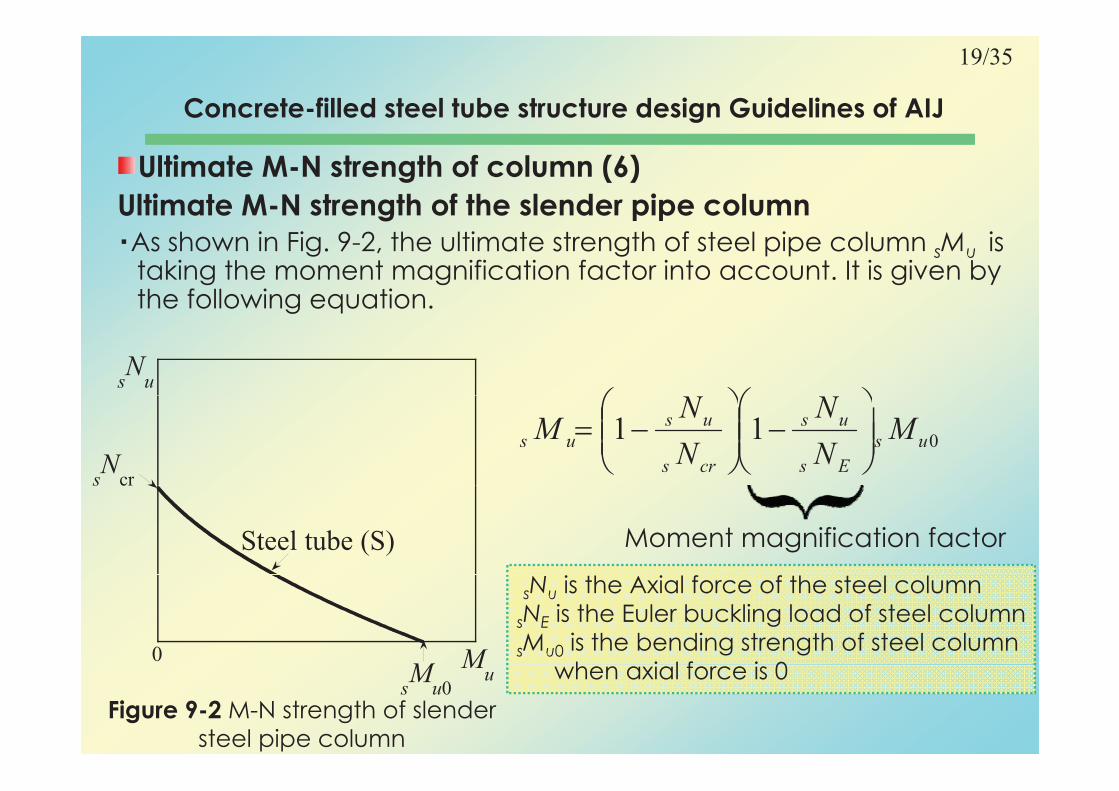
Ultimate M-N strength of column (6)
Ultimate M-N strength of the slender pipe columng p p
As shown in Fig. 9-2, the ultimate strength of steel pipe column sMu is taking the moment magnification factor into account. It is given by the following equation.the following equation.
sN
u
011 us
Es
us
crs
us
us MN
N
N
NM
sN
cr
Steel tube (S)
s cr
Moment magnification factor
MM
0
sNu is the Axial force of the steel column
sNE is the Euler buckling load of steel column
sMu0 is the bending strength of steel column
h i l f i 0
Figure 9-2 M-N strength of slender steel pipe column
Mu
sM
u0when axial force is 0

20/35
Concrete-filled steel tube structure design Guidelines of AIJ
Ultimate M-N strength of column (7)
Superposed strength of slender CFT columnp p gThe strength is determined as simple superposed strength (S + C) of
concrete (C) and steel(S), as shown in Figure 10.
Steel resists primarily bending moment and concrete resists axial
N
Steel resists primarily bending moment, and concrete resists axial force. Both steel and concrete columns must meet the deflection
compatibility, so that bending strength of steel column is reduced by
additional moment
uNMMM 1
When crcu NN 9.0
Nu
Superposed strength(S+C)
Ncu3
additional moment.
k
uusucu
NMMM 10
When>*crcucrc NNN9.0
N
Strength of slender CFT
sNcr
N
When>*
k
uusu
N
NMM 10
crcucu NNN 3
Steel tube (S)cNcr
0.9cNcr
>* crcucu3
k
crcusu
N
NMM 1 Mu
Concrete (C)
sMu00
Figure 10 M-N strength of slender CFT column

21/35
Concrete-filled steel tube structure design Guidelines of AIJ
Ultimate M-N strength of column (8)
Ultimate M-N strength of intermediate column g
When the Nu is below 0.9cNcr , the strength is same as the slender column. While Nu exceeds 0.9cNcr, the strength is interpolated between Ncu2 and the point of M-N interaction corresponding to
Nu
between Ncu2 and the point of M N interaction corresponding to 0.9cNcr.
When crcu NN 9.0
N1
Ncu2
straight line
k
uusucu
N
NMMM 10
When NNN 900.9 NEq.15
When>* crcucu NNN 9.02
crccrcuusu
N
N
NN
NNMM
9.01
10
9.010
0.9cN
cr
k
uusucu
N
NMMM 10
kcrccrs NNN 1.0M
usM
u00
Figure 11 M-N strength of intermediate
column

22/35
Ultimate strength of beam-to-column connection
Ultimate strength of beam-to-column connection
Common details of beam-to-column connections in Japan Common details of beam to column connections in Japan
Three types of standard beam-column joints are used in Japan.
Through diaphragm type is the most popular. Inner diaphragm type is used for super high-rise buildings External diaphragm type is used for super high-rise buildings. External diaphragm type is
becoming popular, so that it is the safest and is easy to fill steel pipe
with concrete.
They are all designed as a rigid moment connection External They are all designed as a rigid moment connection. External diaphragm type is better to be checked in terms of the rigidity and
strength of the diaphragm.
Figure 12 Beam to CFT-column connections

23/35
Ultimate Strength of beam-to-column connections
Ultimate Strength of connection panel
Shear strength of the panel pQu is calculated in Pipe
psQu
Shear strength of the panel pQu is calculated in the superposed strength.
G�Shear Strength of steel pipe is evaluated by the shear strength of pipe web portion.
Pipe
flange
cD
shear strength of pipe web portion.
G�Arch mechanism of concrete in Fig14, there are a main arch and sub arches which are restraint
by steel pipe flanges The plastic hinges are Main arch f t
Sub arch of concrete
Qby steel pipe flanges. The plastic hinges are
formed in steel pipe flanges. of concrete
Sub arch of
pcQu
upcupsup QQQ Sub a c o concrete
Pipe flange
Bd
upcupsup QQQ
32
22
yysups
FnFAQ
s
g
Plastic hinges
Q
32ups Q
ccs
cc
sf
sc
upc FDFD
MDQ sin4tan
2
Figure 14 Plastic collapse mechanism of
arch for concrete part of the joint panel
cD pcQucc
ysf FDt
M4
2

24/35
Construction Statistics of CFT Buildingsgaccording to ANUHT-collected data

25/35
Construction Statistics of CFT Buildings according to
ANUHT-collected dataANUHT-collected data
>Ü>Ü>Ü>Þ
The frequency of total floor area
>ä>Ý
>â>à
>Ý>ß
>Ý>Ø>Ü>Ü>ÜHZ>ß>Ø>Ü>Ü>Ü?�>Þ
HZ>Ý>Ø>Ü>Ü>Ü?�>Þ
>ä>Ü
>Ý>â>à
>Þ>å>Ý
>Þ>à>Æ
>Þ>Ü>Ø>Ü>Ü>ÜHZ>ß>Ü>Ø>Ü>Ü>Ü?�>Þ
>Æ>Ø>Ü>Ü>ÜHZ>Ý>Ü>Ø>Ü>Ü>Ü?�>Þ
? ?�?�
>ß>ß
>Æ>å
>ª>Ü
>ä>Ü
>â>Ü>Ø>Ü>Ü>ÜHZ>ª>Ü>Ø>Ü>Ü>Ü?�>Þ
>à>Ü>Ø>Ü>Ü>ÜHZ>Æ>Ü>Ø>Ü>Ü>Ü?�>Þ
? ? ?�>Ì?�?�?�?�?�>Ì?�?�?
>Ý>å
>Ý>ä
>Þ>Ý
>ä>Ü>Ø>Ü>Ü>ÜHZ>å>Ü>Ø>Ü>Ü>Ü?�>Þ
>â>Ü>Ø>Ü>Ü>Ü >ª>Ü>Ø>Ü>Ü>Ü?�
?�?�?
>â
>Ý>Ý
>â>Æ
>ß>Ü>Ü>Ø>Ü>Ü>Ü?�>ÞHZ
>Ý>Ü>Ü>Ø>Ü>Ü>ÜHZ>Þ>Ü>Ü>Ø>Ü>Ü>Ü?�>Þ
>Ü >Æ>Ü >Ý>Ü>Ü >Ý>Æ>Ü >Þ>Ü>Ü >Þ>Æ>Ü >ß>Ü>Ü >ß>Æ>Ü
>œ?!?�?�?�?�>Ì?�?�>Ì?�? ?�?�?�
Figure 15 The frequency of total floor area

26/35
Construction Statistics of CFT Buildings according to
ANUHT-collected dataANUHT-collected data
The eaves height of the building
>Æ>ÜHZ>Þ>Ü>Ü?�
>Þ>Ü>ÜHIHZ
>â>Ü >Ý>Ü>Ü
>Ý>Ü>ÜHZ>Ý>Æ>Ü?�
?�?
>à>ÆHZ>â>Ü?�
>â>ÜHZ>Ý>Ü>Ü?�
>æ? ?"?�?�>Ì?�?�?�?�?�
>Þ>ÜHZ>ß>Ü?�
>ß>ÜHZ>à>Æ?�
>æ
HZ>Þ>Ü?�
>Ü >Æ>Ü >Ý>Ü>Ü >Ý>Æ>Ü >Þ>Ü>Ü >Þ>Æ>Ü >ß>Ü>Ü >ß>Æ>Ü >à>Ü>Ü >à>Æ>Ü
>œ?!?�?�?�?�>Ì?�?�>Ì?�? ?�?�?�
Figure 16 The eaves height of the building
27/35
Construction Statistics of CFT Buildings according to
ANUHT-collected dataANUHT-collected data
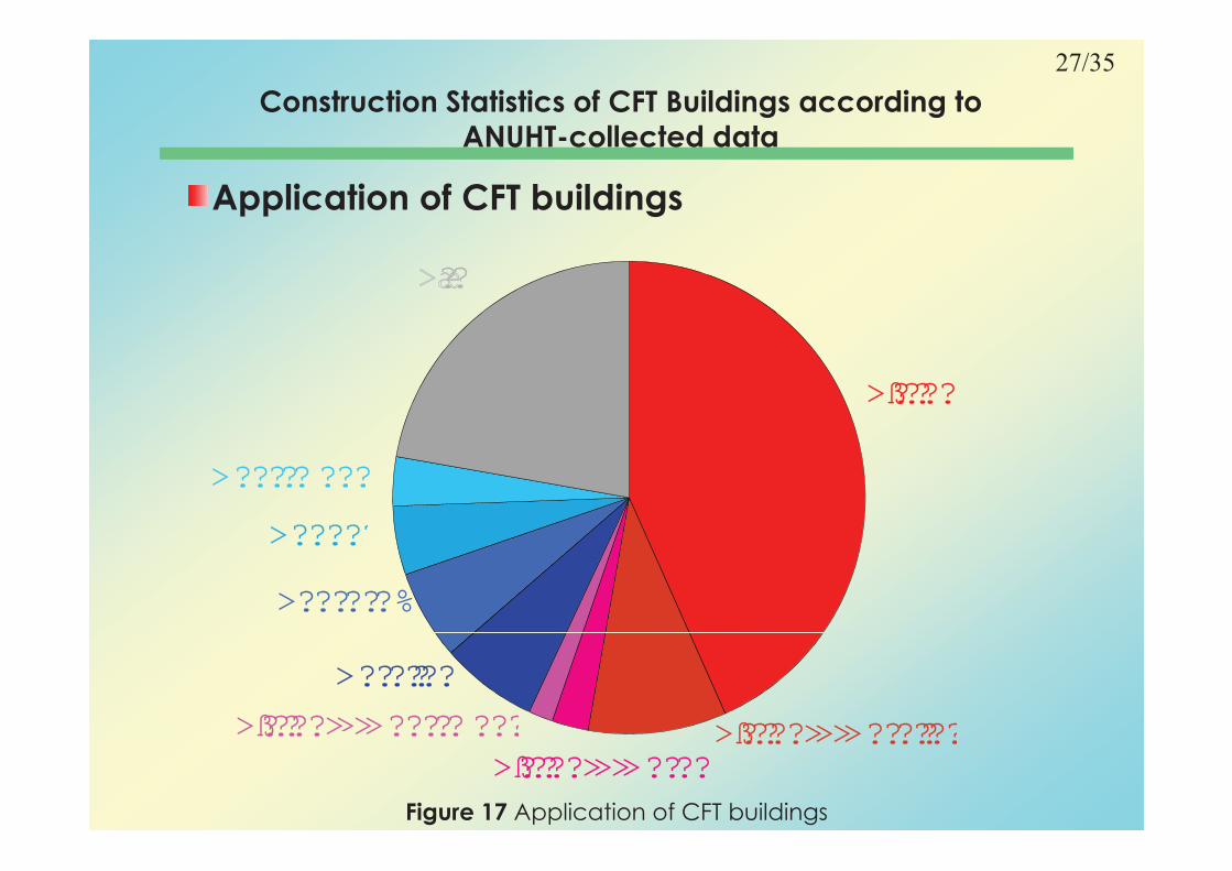
Application of CFT buildings
? ?�
>ß?�?�?�?�?�
>ÿ?�?�?�?�?�
>í?�? ?�? ?�?�?�?
>ò? ?�? ?�?�?%
>ÿ?�?�?�?�?�
>ß?�?�?�?�?�>×>þ?�? ? ?�?�?�?�>ß?�?�?�?�?�>×>í?�? ?�? ?�?�?�?
>þ?�? ? ?�?�?�?�
>ß?�?�?�?�?�>Ì>×>Ì>þ?�? ? ?�?�?�?�
>ß?�?�?�?�?�>Ì>×>Ì>ô?�? ?�?�
>ß?�?�?�?�?�>Ì>Ì>í?�? ?�? ?�?�?�?
Figure 17 Application of CFT buildings
28/35
Construction Statistics of CFT Buildings according to
ANUHT-collected dataANUHT-collected data
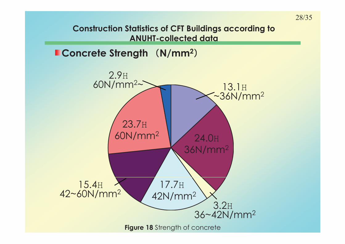
Concrete Strength N/mm2
13.1H�2.9H�
36N/mm2
60N/mm2~
23 7H�
~36N/mm2
24.0H�
23.7H�60N/mm2
36N/mm236N/mm2
17.7H�15.4H�
3 2H�42N/mm242~60N/mm2
3.2H�36~42N/mm2
Figure 18 Strength of concrete

29/35
Construction Statistics of CFT Buildings according to
ANUHT-collected dataANUHT-collected data
The shape of cross section
19.4 17.7
62.9
Figure 19 The shape of the cross section

35/35
Summary
Structure design method of Japan (Primarily seismic design) can be selected from several.
The research of CFT began from 1960 in Japan, but it did not spread until it is recognized as the general structure by p g g ybuilding standard in 2002.
In Japan, structural design of CFT has been done in ANUHT In Japan, structural design of CFT has been done in ANUHT guidelines and AIJ guidelines.
AIJ guidelines applicable range is wide AIJ guideline shows AIJ guidelines applicable range is wide. AIJ guideline shows the design method of slender column and beam-to-column connection. For all of them, superposed strength is applied.
CFT is mainly used in the office building and it is also used in relatively small buildings by ANUHT statistics.
A couple of recent CFT buildings are introduced.

36/35
Thank you for your attentionThank you for your attention
“Ito” new campus plan “Ito” new campus plan
of Kyushu University of Kyushu University of Kyushu University of Kyushu University