Embed Size (px)
Citation preview

12th International Conference on Advances in Steel-Concrete Composite Structures (ASCCS 2018) Universitat Politècnica de València, València, Spain, June 27-29, 2018
Doi: http://dx.doi.org/10.4995/ASCCS2018.2018.8273
2018, Universitat Politècnica de València
Numerical study of concrete-filled austenitic stainless steel CHS stub columns with high-strength steel inner tubes
F. Wanga*, B. Younga and L. Gardnerb a Department of Civil Engineering, The University of Hong Kong, Hong Kong, China b Department of Civil and Environmental Engineering, Imperial College London, UK *corresponding author, e-mail address: [email protected]
Abstract A numerical modelling programme simulating the structural behaviour of concrete-filled double skin tubular (CFDST) stub columns with stainless steel outer tubes and high strength steel inner tubes is presented in this paper. The numerical model, which was developed using the finite element package ABAQUS, was initially validated against existing experimental results considering ultimate load, load-deflection histories and failure modes, with good agreement observed. Upon validation of the FE model, an extensive parametric study was undertaken whereby the cross-section slendernesses of the outer and inner tubes, the strength of the inner tube and the concrete grades were varied. These generated results together with the experimental data were then employed to assess the suitability of the design provisions of the European Standard EN 1994-1-1 and American Specification for concrete-filled tubes. Modifications to these design rules are also proposed, and a reduction factor (η) is suggested to account for the effective compressive strength in high strength concrete.
Keywords: Concrete-filled double skin tubular (CFDST); high-strength steel; numerical analysis; parametric studies; stainless steel; structural design.
1. Introduction Concrete-filled double skin tubular (CFDST)
sections comprise two metal tubes—an outer tube and an inner tube—with concrete sandwiched between the tubes. CFDST sections have gained popularity owing to benefits that they could offer over plain concrete sections, hollow steel tubular sections and concrete-filled tubular (CFT) sections. These benefits include high strength, stiffness and ductility similar to other composite sections, no requirement for temporary formwork, and lightness in comparison to CFT sections [1].
The authors of this paper conducted an experimental investigation into the structural behaviour of CFDST stub columns with stainless steel outer tubes and high strength steel inner tubes, and the test results have been detailed in [2]. In the present paper, the development of a finite element model of CFDST stub columns is described, followed by a presentation of the validation of the numerical model against the
experimental results. An extensive parametric study, expanding the available data pool to a wider range of cross-section slendernesses and material strengths, is then described. All the numerically derived data, together with the experimental results, are compared with the strength predictions from the European Standard EN 1994-1-1 (EC4) [3] and American Specification (AISC 360) [4], enabling the suitability of these existing design rules to be assessed. Finally, modifications to the design rules incorporating the effective compressive strength of concrete are also assessed.
2. Numerical modelling
2.1. Introduction The experimental investigation into the
structural performance of CFDST stub columns conducted by the authors is reported in [2]. A total of 14 tests was carried out on the CFDST stub columns with circular hollow section (CHS) stainless steel outer tubes and CHS high strength
343

Wang, F., Young, B. and Gardner, L.
2018, Universitat Politècnica de València
steel inner tubes. The list of tested specimens and their dimensions are detailed in [2]. Owing to the expense and impracticality of generating comprehensive data through experimentation, a numerical study was undertaken in parallel with the laboratory testing programme. The general purpose finite element (FE) analysis package ABAQUS [5] was employed throughout the study. The model generated from ABAQUS was validated against the experimental results of [2] by comparing ultimate loads, load-deformation histories and failure modes. Once satisfactory agreement between the experimental and numerical results was achieved, an extensive parametric study comprising 239 simulations was conducted to investigate the influence of key variables.
2.2. Description of finite element model The numerical model was developed using
ABAQUS [5]. Numerical investigations of concrete-steel composite columns have been reported in [6–10]. In this study, four-noded doubly curved shell elements with reduced integration (S4R) were employed to model the metal tubes, while eight-noded brick elements with three translational degrees of freedom at each node (C3D8R) were used for the concrete. Convergence studies were conducted to decide upon a suitable mesh density, with the aim of achieving suitably accurate results whilst minimizing computational time. A uniform mesh size of πD/20 and D/20, where D is the tube diameter, was assigned along the circumferential and longitudinal directions of the model, respectively.
The material stress-strain behaviour was specified by means of a multi-linear stress-strain curve, defined in terms of true stress and log plastic strain. The relationships between true stress (σtrue) and engineering stress (σnom), and log plastic strain (εln
pl) and engineering strain (εnom), are given in Eqs. (1) and (2), respectively.
(1 )true nom nom (1)
ln ln(1 )pl nomnom E
(2)
The classic metal plasticity model defined in ABAQUS [5] was used for the outer stainless steel tubes and inner high strength steel tubes, with the von Mises yield surface and isotropic hardening. Engineering stresses and strains for the outer and inner tubes were recorded from uniaxial coupon tests. Each test coupon curve
comprised at least 100 intervals, in order to accurately capture a full range of the stress-strain response. The measured steel material properties given in [2] were incorporated into the model for validation purposes and were subsequently employed in the parametric study.
The concrete damage plasticity (CDP) model defined in ABAQUS [5] was used for the sandwiched concrete. In order to account for the effect of confinement provided by the metal tubes, a confined concrete model based on that proposed by Tao et al. [8] was adopted in this study. The model in [8] was originally proposed for CFST stub columns and calibrated against tests for CFST stub columns under axial compression. For CFDST stub columns, the inner tube restricts the inner deformation of the sandwiched concrete; thus, the concrete has similar behaviour with that in CFST stub columns [7]. It is therefore assumed that the behaviour of the concrete in CFDST is similar to that of fully filled CFST specimens, and the model in [8] was employed herein. For application to CFDST members, confinement factor (ξc) for CFST was modified, as given by Eq. (3) and (4),
0.2,o oc
ce c
AA f
(3)
2( 2 )4ce o oA D t
(4)
where Ao is the cross-sectional area of the outer tube, Ace is the nominal cross-sectional area of the concrete, σ0.2,o is the 0.2% proof stress of the stainless steel outer tube, fc is the compressive cylinder strength of the concrete, Do is the outer diameter of the outer tube and to is the thickness of the outer tube. The confined stress-strain curves were used in the present study in conjunction with the CDP model in ABAQUS [5], using the following parameters: the ratio of the second stress invariant on the tensile meridian to that on the compressive meridian (Kc), the dilation angle (ψ), the flow potential eccentricity (e), the ratio of the compressive strength under biaxial loading to uniaxial compressive strength (fb0/fc′), and viscosity parameter (μ); their values were determined in accordance with the recommendations given in [8]. Following guidance from ACI 318 [11], the modulus of elasticity Ec of concrete was defined as 4700 cf and the Poisson’s ratio of concrete was set at 0.2. The uniaxial tensile response was
344
Wang, F., Young, B. and Gardner, L.
2018, Universitat Politècnica de València
assumed to be linear until the tensile strength of the concrete (taken as 0.1fc) was reached, beyond which the inelastic portion of the tensile stress-strain curve was characterized by means of fracture energy (GF), determined from Eq. (5),
0.72
max max(0.0469 0.5 26)10
cF
fG d d
(5)
where fc is in MPa and dmax is the maximum coarse aggregate size in mm, taken as 10 mm in the validation study, and as 20 mm in the parametric study.
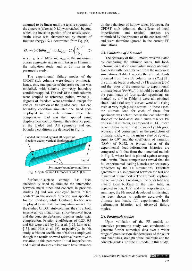
The experimental failure modes of the CFDST stub columns were doubly symmetric; hence, only one quarter of the cross-section was modelled, with suitable symmetry boundary conditions applied. The ends of the stub columns were coupled to reference points, where all degrees of freedom were restrained except for vertical translation at the loaded end. This end boundary condition simulated the fixed ends employed in the stub column tests. The compressive load was then applied using displacement control through the reference point at the loaded end. All symmetry and end boundary conditions are depicted in Fig. 1.
Fig. 1. Stub column FE model in ABAQUS.
Surface-to-surface contact has been successfully used to simulate the interaction between metal tubes and concrete in previous studies [8] and was employed herein. “Hard contact” in the normal direction was specified for the interface, while Coulomb friction was employed to simulate the tangential contact. For the studied CFDST stub columns, the slip at both interfaces was insignificant since the metal tubes and the concrete deformed together under axial compression. Friction coefficients of 0.25, 0.3 and 0.6 were used by Hu et al. [12], Lam et al. [13], and Han et al. [6], respectively. In this study, a friction coefficient of 0.6 was employed, though the results showed relative insensitive to variation in this parameter. Initial imperfections and residual stresses are known to have influence
on the behaviour of hollow tubes. However, for CFDST stub columns, the effects of local imperfections and residual stresses are minimized by the presence of the concrete infill and were therefore ignored in the current FE simulations.
2.3. Validation of FE model The accuracy of the FE model was evaluated
by comparing the ultimate loads, full load-deformation histories and failure modes obtained from tests with those derived from the numerical simulations. Table 1 reports the ultimate loads obtained from the stub column tests (Pexp) [2], the ultimate loads predicted by FE analysis (PFE) and the ratios of the numerical to experimental ultimate loads (PFE/Pexp). It should be noted that the peak loads of four stocky specimens (as marked by a * in Table 1) were not obtained since load-axial strain curves were still rising even at very high plastic strains. In these cases, the ultimate load for each of these four specimens was determined as the load where the slope of the load-axial strain curve reaches 1% of its initial stiffness, as proposed in [14]. It can be seen from Table 1 that the model yields good accuracy and consistency in the prediction of ultimate loads, with the mean value of PFE/Pexp equal to 0.97 and the coefficient of variation (COV) of 0.042. A typical series of the experimental load-deformation histories are compared with that from the numerical models in Fig. 2, where load is plotted against average axial strain. These comparisons reveal that the full experimental loading histories are accurately replicated by the FE simulations. Excellent agreement is also obtained between the test and numerical failure modes. The FE model captured the outward local buckling of the outer tube and inward local bucking of the inner tube, as depicted in Fig. 3 (a) and (b), respectively. In summary, the FE model developed in this study has been shown to replicate accurately the ultimate test loads, full experimental load-deformation histories and observed failure modes.
2.4. Parametric studies Upon validation of the FE model, an
extensive parametric study was conducted to generate further numerical data over a wider range of cross-section slendernesses of the outer and inner tubes, strength of the inner tube and the concrete grades. For the FE model in this study,
Loaded end fixed against all degree of freedom except vertical displacement
Fixed
again
st all
degre
Symmetry boundary conditions
345

Wang, F., Young, B. and Gardner, L.
2018, Universitat Politècnica de València
Table 1. Comparison of test results with FE results for stub columns.
Specimen label Do/to Di/ti Pexp PFE PFE/Pexp (kN) (kN) AC140×3-HC22×4-C40* 48.0 5.4 1410 1373 0.97 AC140×3-HC22×4-C80 48.2 5.4 1845 1881 1.02 AC140×3-HC22×4-C120 48.5 5.4 2321 2303 0.99 AC140×3-HC32×6-C40* 48.5 5.8 1423 1492 1.05 AC140×3-HC32×6-C80 48.0 6.1 2012 1930 0.96 AC140×3-HC32×6-C120 48.2 5.9 2537 2343 0.92 AC140×3-HC38×8-C40* 48.1 5.0 1626 1545 0.95 AC140×3-HC38×8-C80 48.3 5.1 2083 1933 0.93 AC140×3-HC38×8-C120 48.4 5.1 2500 2348 0.94 AC140×3-HC55×10-C40* 48.3 5.2 2543 2351 0.92 AC140×3-HC55×10-C80 48.4 5.1 2775 2663 0.96 AC140×3-HC89×4-C40 48.9 22.9 2025 1980 0.98 AC140×3-HC89×4-C80 49.0 22.8 2107 2039 0.97 AC140×3-HC89×4-C120 48.6 22.8 2195 2279 1.04 Mean 0.97 COV 0.042
Fig. 2. Comparisons of test and FE load-average
axial strain curves.
the measured material properties obtained from tensile coupon tests [2] were adopted. The stress-strain curve of the austenitic stainless steel AC140×3 section was employed for all the outer tubes, while comparative studies were performed with three different grades of high strength steel inner tube with nominal 0.2% proof stresses (σ0.2,i) of 460, 740 and 1100 MPa. The key material properties of the selected grades are summarised in Table 2. The outer diameter of the modelled outer tubes ranged from 200 mm to 600 mm, with the thickness varying between 2 mm and 20 mm, resulting in the ratios of (Do/to)(σ0.2/Eo) ranging between 0.015 to 0.305, covering compact, non-compact and slender cross-sections, according to the slenderness limits in AISC 360 [4]. The cross-section slendernesses of the inner tubes were
also varied (8-150) to cover a broad range of slendernesses. Three concrete strengths, 40, 80 and 120 MPa were adopted for sandwiched concrete. The ranges of abovementioned parameters are summarised in Table 3. For all the modelled specimens, the lengths were set equal to 2.5 times the outer diameters (Do). In total, 239 specimens were modelled in the parametric study.
(a) Outward local buckling of outer tube
(b) Inward local buckling of inner tube
Fig. 3. Comparisons of test and FE failure modes for stub column AC140×3-HC89×4-C40.
0
500
1000
1500
2000
2500
3000
0 0,01 0,02 0,03
Load
(kN
)
Average axial strain ԑ
TestFE
AC140×3-HC22×4-C120
AC140×3-HC22×4-C40*
AC140×3-HC22×4-C80
346

Wang, F., Young, B. and Gardner, L.
2018, Universitat Politècnica de València
Table 2. Summary of key measured material properties from tensile coupon tests [2].
Section 0.2 (MPa)
u
(MPa)
E (GPa)
εf (%) n
AC140×3 300 705 197 62 5 HC38×8 433 765 197 15 6 HC55×11 739 941 211 9 8 HC89×4 1029 1093 209 6 6
Table 3. Ranges of variation of parameters for the parametric study.
Parameters Do/to Di/ti fc
(MPa) σ0.2,i
(MPa)
Range Max. 200 150 120 1029 Min. 10 8 40 433
3. Discussion and assessment of current design rules
3.1. General Concrete-filled double skin sections with
either carbon steel or stainless steel tubes are not explicitly covered by current design codes. Two existing design rules for concrete-filled tubes in the European code EN 1994-1-1 [3] and American specification AISC 360-16 [4] are described. The accuracy of these design rules is then assessed against the generated test and FE results. Note that all comparisons have been made based on the measured material and geometric properties and on the unfactored design strengths. In addition, the code limitations on the concrete strength and steel strength were often exceeded, but comparisons made nonetheless.
3.2. European code EN 1994-1-1 (EC4) The compressive design resistance of
concrete-filled columns with a carbon steel circular outer tube is given in Eq. (6.33) of EC4 [3]. In this study, stainless steel was used in place of carbon steel for the outer tube. Therefore, the 0.2% proof stress is used instead of the yield stress in calculating the column strengths. Furthermore, the term in Eq. (6.33) of EC4 [3] relating to the reinforcing bars is replaced by the high strength steel inner tube. Account is taken of the increase in strength of the concrete due to the confinement effect, and the decrease in strength of the outer steel tube due to the biaxial stress state [3]. Hence, the experimental and numerical results are compared with the design
predictions of Eq. (6), which is a modified version of Eq. (6.33) of EC4 [3], accounting for the aforementioned effects.
0.2,4 0.2, 0.2,1 oo
EC o o o c c c i io c
tP A A f AD f
(6) where ηo and ηc are functions of the relative slenderness for pure compression, given in EC4 [3] by Eqs (7) and (8).
0.25 3 + 2 1.0o ( ) (7) 2
4.9 18.5 +17 0c (8)
where is the relative slenderness as defined in Eq. (6.39) of EC4 [3]; an effective length factor of 0.5 was used in the present study for the fixed-ended boundary conditions. It should be noted that EC4 [3] is currently limited to columns with normal weight concrete of strength classes C20/C25 to C50/C60 and steel grades from S235 to S460. Most of the test specimens and FE simulations fall outside these limits. A limit on the slenderness of the outer tube of D/t90(235/fy) is also specified in EC4 [3], beyond which local buckling needs to be explicitly accounted for. In this study, the limit has been modified for stainless steel to consider the differences in material yield strength and stiffness, given by Do/to ≤ 90(235/σ0.2,o)(Eo/210000).
It is worth noting that this limit for concrete-filled tubes is identical to the class 3 slenderness limit for hollow tubes, i.e. the beneficial effect of concrete infill inhibiting inward local buckling of the outer tube is ignored. Further investigation should be conducted to determine an appropriate limit for concrete filled tubes. For sections exceeding the limits, a preliminary effective area formula (Aeff) has been developed with reference to the formulation for CHS in BS 5950-1 [15], as proposed by Chan and Gardner [16]. This preliminary formula is modified for stainless steel and given by Eq. (9).
0.5
0.2
90 235210000
oeff
o o
EA AD t
(9)
A comparison of the test and FE results with the strength predictions from EC4 [3] is shown in Fig. 4, where the ratio of test (or FE) strength-to-predicted strength has been plotted against the
347

Wang, F., Young, B. and Gardner, L.
2018, Universitat Politècnica de València
cross-section slenderness of the outer tube λ. A limiting value of 90 is also plotted in Fig. 4. There is a trend that as slenderness increases, EC4 [3] yields less conservative but less scattered predictions. The conservatism at low slenderness values may be attributed to the lack of consideration of strain hardening in the stainless steel outer tube and the high strength inner tube.
The mean ratio of the experimental and numerical results (Pu) to the strength predictions from EC4 (PEC4) is equal to 1.01 and the corresponding COV is 0.091, as reported in Table 4. It can be seen that design models in EC4 [3] developed for concrete-filled carbon steel tubular sections offer generally good average strength predictions for CFDST stub columns with stainless steel outer tubes, though there are many results on the unsafe side.
Fig. 4. Comparison of test and FE results with
strength predictions from EC4 [3].
Table 4. Comparisons of test and finite element results with predicted strengths.
No. of tests: 14 Pu/PEC Pu/PAISC
No. of FE simulations: 239 Mean 1.01 1.20 COV 0.091 0.116
3.3. American specification AISC 360 The AISC 360 [4] Specification for the
design of filled composite members with carbon steel outer tubes is also adopted herein to predict the axial capacity of the CFDST stub columns. The ultimate axial strengths (PAISC) of the CFDST columns can be obtained from Eq. (I2-2) of AISC 360 [4], which is also shown in Eq. (10).
(0.658 )no
e
PP
AISC noP P when 2.25no
e
PP
(10)
where Pe is the elastic critical buckling load determined in accordance with Eq. (I2-5) of AISC 360 [4], and the effective length factor was again taken as 0.5 in the calculation. The nominal compressive section strengths (Pno) of the columns are calculated according to the compactness of the composite section. Filled composite sections are categorized into compact, noncompact and slender sections according to the diameter-to-thickness ratios of the outer tube. A compact section can reach the yield strength in the metal tube and develop a concrete compressive strength of 0.95fc due to good confinement being afforded by from the metal tube. A noncompact section is only capable of confining the concrete to a lesser extent, with 0.70 fc being achieved, after which the concrete volumetric dilation cannot be confined adequately since the noncompact metal tube undergoes local buckling [17]. A slender section can neither develop the yield strength of metal tube nor confine the concrete beyond achieving 0.70 fc [18]. The limiting Do/to values, i.e. p for compact/noncompact and r for noncompact/ slender, are detailed in Table 4 and plotted in the Fig. 5.
In this study, the yield stress was again taken as the 0.2% proof stress in calculating the column strengths, and the term relating to the reinforcing bars is again replaced by the cold-formed high strength steel inner tube. However, the structural behaviour of the inner tube is different from that of the reinforcing bar. Reinforcing bars may fail to take further loads upon crushing of the concrete, whereas the inner tube still takes loads after the concrete fails. Therefore, the contribution of the reinforcing bars is considered as a dependent term through strain compatibility of the concrete and the reinforcing bars in Eq. (I2-9b), while the contribution of the inner tube should be treated as an independent term. The nominal compressive section strengths (Pno) of the columns are calculated from Eq. (11) - (15) for compact, noncompact and slender sections.
0.2, 0.2,0.95compact p o o c c i iP P A f A A
(11)
2
0.2,2p y
noncompact y p i i
r p
P PP P A
(12)
0.2, 0.2,0.7y o o c c i iP A f A A (13)
0,8
1,0
1,2
1,4
1,6
1,8
2,0
0 60 120 180 240 300
P u/P
EC4
=Do/(toε2)
FE-EC4Test-EC4
90
348
Wang, F., Young, B. and Gardner, L.
2018, Universitat Politècnica de València
0.2,0.7slender o cr c c i iP A f f A A (14)
0.2,0.2
0.2,
0.72 ocr
oo
o o
fDt E
(15)
where is the slenderness of the outer tube and fcr is the critical buckling stress of the CHS outer tube.
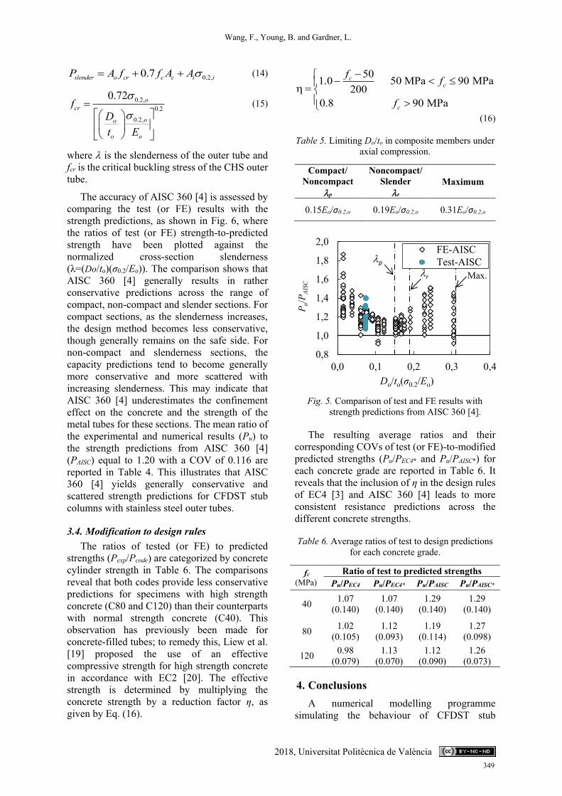
The accuracy of AISC 360 [4] is assessed by comparing the test (or FE) results with the strength predictions, as shown in Fig. 6, where the ratios of test (or FE) strength-to-predicted strength have been plotted against the normalized cross-section slenderness (λ=(Do/to)(σ0.2/Eo)). The comparison shows that AISC 360 [4] generally results in rather conservative predictions across the range of compact, non-compact and slender sections. For compact sections, as the slenderness increases, the design method becomes less conservative, though generally remains on the safe side. For non-compact and slenderness sections, the capacity predictions tend to become generally more conservative and more scattered with increasing slenderness. This may indicate that AISC 360 [4] underestimates the confinement effect on the concrete and the strength of the metal tubes for these sections. The mean ratio of the experimental and numerical results (Pu) to the strength predictions from AISC 360 [4] (PAISC) equal to 1.20 with a COV of 0.116 are reported in Table 4. This illustrates that AISC 360 [4] yields generally conservative and scattered strength predictions for CFDST stub columns with stainless steel outer tubes.
3.4. Modification to design rules The ratios of tested (or FE) to predicted
strengths (Pexp/Pcode) are categorized by concrete cylinder strength in Table 6. The comparisons reveal that both codes provide less conservative predictions for specimens with high strength concrete (C80 and C120) than their counterparts with normal strength concrete (C40). This observation has previously been made for concrete-filled tubes; to remedy this, Liew et al. [19] proposed the use of an effective compressive strength for high strength concrete in accordance with EC2 [20]. The effective strength is determined by multiplying the concrete strength by a reduction factor η, as given by Eq. (16).
501.0 50 MPa 90 MPa 200
0.8 90 MPa
cc
c
f f
f
(16)
Table 5. Limiting Do/to in composite members under axial compression.
Compact/ Noncompact
p
Noncompact/ Slender
r Maximum
0.15Eo/σ0.2,o 0.19Eo/σ0.2,o 0.31Eo/σ0.2,o
Fig. 5. Comparison of test and FE results with strength predictions from AISC 360 [4].
The resulting average ratios and their corresponding COVs of test (or FE)-to-modified predicted strengths (Pu/PEC4* and Pu/PAISC*) for each concrete grade are reported in Table 6. It reveals that the inclusion of η in the design rules of EC4 [3] and AISC 360 [4] leads to more consistent resistance predictions across the different concrete strengths.
Table 6. Average ratios of test to design predictions for each concrete grade.
fc (MPa)
Ratio of test to predicted strengths Pu/PEC4 Pu/PEC4* Pu/PAISC Pu/PAISC*
40 1.07 (0.140)
1.07 (0.140)
1.29 (0.140)
1.29 (0.140)
80 1.02 (0.105)
1.12 (0.093)
1.19 (0.114)
1.27 (0.098)
120 0.98 (0.079)
1.13 (0.070)
1.12 (0.090)
1.26 (0.073)
4. Conclusions A numerical modelling programme
simulating the behaviour of CFDST stub
0,8
1,0
1,2
1,4
1,6
1,8
2,0
0,0 0,1 0,2 0,3 0,4
P u/P
AISC
Do/to(σ0.2/Eo)
FE-AISCTest-AISCp
r Max.
349

Wang, F., Young, B. and Gardner, L.
2018, Universitat Politècnica de València
columns with stainless steel outer tubes and high strength steel inner tubes has been developed in ABAQUS [5]. The model was initially validated against existing experimental results for ultimate load, load-deflection histories and failure modes. An extensive parametric study comprising 239 specimens was then conducted to generate further data over a range of cross-section slendernesses of the outer and inner tubes, strengths of inner tube, concrete grades. The derived results, together with the experimental data, were employed to assess the suitability of the provisions in the current European Standard EN 1994-1-1 [3] and American Specification AISC 360-16 [4] for composite structures for the design of CFDST cross-sections. Modifications are also proposed, and a reduction factor (η) is used to account for the effective compressive strength of high strength concrete. The comparisons revealed that the current design rules in EC4 [3] and AISC 360 [4] can be generally safely applied to CFDST stub columns with stainless steel outer tubes and high strength steel inner tubes, while the approach of using the effective concrete strengths allows concrete strength in CFDST to be safely extended to 120 MPa.
References [1] Lu H, Han LH, Zhao XL. Fire performance of
self-consolidating concrete filled double skin steel tubular columns: Experiments. Fire Safety Journal 2010; 45(2): 106-115.
[2] Wang F, Young B, Gardner L. Experimental investigation of concrete-filled double skin tubular stub columns with stainless steel outer tubes. Proceedings of the 8th International Conference on Steel and Aluminium Structures. Hong Kong; 2016; 118.
[3] European Committee for Standardization. Eurocode 4: Design of composite steel and concrete structures—Part 1-1: General Rules and Rules for Buildings. EN 1994-1-1. Brussels; 2004.
[4] American Institute of Steel Construction, Inc. Specification for structural steel buildings. ANSI/AISC 360-16. Chicago; 2016.
[5] ABAQUS. ABAQUS/standard user’s manual. Version 6.17. Dassault Systemes Simulia Corp. USA; 2017.
[6] Han LH, Yao GH, Tao Z. Performance of concrete-filled thin-walled steel tubes under pure torsion. Thin-Walled Structures 2007; 45(1): 24-36.
[7] Huang H, Han LH, Tao Z, Zhao XL. Analytical behaviour of concrete-filled double skin steel
tubular (CFDST) stub columns. Journal of Constructional Steel Research 2010; 66(4): 542-55.
[8] Tao Z, Wang ZB, Yu Q. Finite element modelling of concrete-filled steel stub columns under axial compression. Journal of Constructional Steel Research 2013; 89: 121-31.
[9] Espinós A, Gardner L, Romero ML, Hospitaler A. Fire behaviour of concrete filled elliptical steel columns. Thin-Walled Structures 2011; 49(2): 239-55.
[10] Espinós A, Romero ML, Lam D. Fire performance of innovative steel-concrete composite columns using high strength steels. Thin-Walled Structures 2016; 106: 113-28.
[11] ACI (American Concrete Institute). Building code requirements for structural concrete and commentary. ACI 318-14, Michigan; 2014.
[12] Hu HT, Su FC. Nonlinear analysis of short concrete-filled double skin tube columns subjected to axial compressive forces. Marine Structures 2011; 24(4): 319-37.
[13] Lam D, Dai XH, Han LH, Ren QX, Li W. Behaviour of inclined, tapered and STS square CFST stub columns subjected to axial load. Thin-Walled Structures 2012; 54: 94-105.
[14] Dos Santos GB, Gardner L, Kucukler M. A method for the numerical derivation of plastic collapse loads. Thin-Walled Structures 2018; 124: 258-77.
[15] Bristish Standard. Structural Use of Steelwork in Building—Part 1: Code of Practice for Design—Rolled and Welded Sections, BS 5950-1; 2000.
[16] Chan TM, Gardner L. Compressive resistance of hot-rolled elliptical hollow sections. Engineering Structures 2008; 30(2): 522-32.
[17] Chen WF, Han DJ. Plasticity for structural engineers. J. Ross Publishing. FL; 2007.
[18] Lai Z, Varma AH, Zhang K. Noncompact and slender rectangular CFT members: Experimental database, analysis, and design. Journal of Constructional Steel Research 2014; 101: 455-468.
[19] Liew JR, Xiong M, Xiong D. Design of concrete filled tubular beam-columns with high strength steel and concrete. Structures 2016; 8: 213-226.
[20] European Committee for Standardization. Eurocode 2: Design of concrete structures-Part 1-1: General rules and rules for buildings. EN 1992-1-1, Brussels; 2004.
350