Embed Size (px)
Citation preview
Purdue UniversityPurdue e-Pubs
International Compressor Engineering Conference School of Mechanical Engineering
2018
Design And Validation Of An Adjustable DynamicVibration Absorber For Piping VibrationSuppression In Skid Mounted Compressor UnitChang LiuXi\'an Jiaotong University, Xi’an, China, [email protected]
Jie NiAtlas Copco (Wuxi) Compressor Co., LTD, Wuxi, China, [email protected]
Jie WenXi'an Jiaotong University, China, People's Republic of, [email protected]
Xueyuan PengXi'an JiaoTong University, China, People's Republic of, [email protected]
Follow this and additional works at: https://docs.lib.purdue.edu/icec
This document has been made available through Purdue e-Pubs, a service of the Purdue University Libraries. Please contact [email protected] foradditional information.Complete proceedings may be acquired in print and on CD-ROM directly from the Ray W. Herrick Laboratories at https://engineering.purdue.edu/Herrick/Events/orderlit.html
Liu, Chang; Ni, Jie; Wen, Jie; and Peng, Xueyuan, "Design And Validation Of An Adjustable Dynamic Vibration Absorber For PipingVibration Suppression In Skid Mounted Compressor Unit" (2018). International Compressor Engineering Conference. Paper 2574.https://docs.lib.purdue.edu/icec/2574
1312, Page 1
24th International Compressor Engineering Conference at Purdue, July 9-12, 2018
Design and Validation of an Adjustable Dynamic Vibration Absorber for Piping Vibration
Suppression in Skid Mounted Compressor Unit
Chang LIU1*, Jie NI2, Jie WEN1, Xueyuan PENG1
1 Xi’an Jiaotong University,
Xi’an, Shaanxi, China
+86 029 82663785, +86 02982668724, [email protected]
2 Atlas Copco (Wuxi) Compressor Co., LTD,
Wuxi, Jiangsu, China
* Corresponding Author
ABSTRACT
The vibration control for a reciprocating compressor as well as piping has always been a challenge. Because of
compact installation and limited space for the skid mounted compressor unit, it is difficult to arrange a piping support
freely or change the piping layout. A new type of adjustable dynamic vibration absorber (DVA), consisting of an
annular clamp and several discrete spring-mass systems (DVA subsystem), was proposed to solve this problem. The
spring-mass system of this new DVA used the electromagnet and leaf spring equipped with linear slideway, which
permitted continuous adjustment of the DVA’s natural frequency by means of variation of the mass and change of the
electromagnet’s position. The finite element models of the piping with DVA was established to analyze the harmonic
responses in the case of pre- and post- installation of DVA so as to validate the DVA performance of vibration
suppression. The results showed that this DVA could suppress vibration effectively at original resonance frequency.
Compared with the traditional DVA, multiple distributed units of DVA subsystems in an annular clamp could obtain
a much wider frequency band, which overcame the defect that two resonance peaks appeared after installing the
traditional DVA. The results also showed that this DVA, equipped with multiple sets of DVA subsystems with
different natural frequencies, had an effective vibration suppression for the piping vibration simultaneously excited
by multiple resonant frequencies. The study indicates that this novel adjustable DVA can effectively damp the piping
vibration of the skid mounted compressor unit.
Keywords: dynamic vibration absorber, skid mounted compressor, vibration control, piping vibration
1. INTRODUCTION
The vibration control for a reciprocating compressor unit has always been a challenge. The vibration in a skid mounted
compressor unit is mainly cause by the reciprocating compressor [1] and it will reduce the reliability of pipelines,
equipment and meters. In the majority of cases, the vibration attenuation measures contain the reasonable design of
piping, the installation of damper or pulsation attenuator and the use of damping materials [2]. However, for a skid
mounted compressor unit already in service, due to its compact installation and limited space, it is difficult to change
the piping layout or arrange a piping support freely. This DVA is very suitable for pipelines that resonate but are
difficult to increase support.
In 1909, some scholars put forward an undamped dynamic vibration absorber (DVA) that consisted of mass and spring.
Ormondroy (1928) [3] pointed out that the damped dynamic absorber was the most effective and had the optimal
damping for the excitation frequency variations. Brock (1946) [4] formulated the conditional formula for optimal
damping. Since the latter half of the 1960s, the multiple DVAs and active DVAs have become the research focuses.
In recent years, many scholars have carried out further theoretical research and engineering applications of DVAs.
Generally, the DVA has a prominent performance of vibration suppression when its nature frequency approach the
1312, Page 2
24th International Compressor Engineering Conference at Purdue, July 9-12, 2018
one of the structure or the excitation force. Nonetheless, the narrow vibration absorption band of DVA often lead to
the detuning problem. Some scholars widened absorption band by means of the increase of damping value of DVA [5], the use of duplex DVA [6] and so on. These methods did widen the absorption band but the frequency band is unable
to change continuously for a DVA. To put it another way, different piping system needs manufacture different DVA
according to the specific natural frequency. Sheng, Z. (2012) [7] proposed a tuned mass damper for the pipe system
and Jinxiu, H. (2015) [8] designed a controllable ring DVA. However, these DVAs’ structure is complex, which cannot
easily realize installation and frequency adjustment.
This paper proposes an adjustable DVA for the pipelines. The device has the advantages of simple structure and
convenient installation. The resonance frequency can be adjusted continuously in a wide range to meet the
requirements of vibration control in various operating conditions of the pipeline. The numerical methods are applied
to verify the feasibility of the new adjustable DVA. This paper provides a new idea for resonance avoidance of the
skid mounted reciprocating compressor unit under various working conditions.
2. THEORY OF DYNAMIC VIBRATION ABSORBER TECHNOLOGY
Piping system is a continuous system. Generally, the finite element method or the transfer function method is used to
convert this continuous system into a multi-degree-of-freedom (multi-dof) model. Although the vibration of the multi-
DOF vibration system contains various order modes, if there is a huge gap between each order modal frequencies,
vibration of a single mechanical natural frequency (MNF) occurs in the system at one resonance frequency. At this
point, the mutual influence between each mode can be ignored and the vibration on every modal frequency can be
controlled respectively [9]. The resonance occurs when the excitation frequency is equal to the natural frequency of
the system. By adding a subsystem to the main system, the natural frequency of the main system can be kept away
from the excitation frequency and the vibration of the system can be reduced. The subsystem is called DVA. The
dynamic vibration absorption technique is based on the principle of anti-resonance. It can transform the resonance of
the main system at the excitation frequency to the resonance of subsystem.
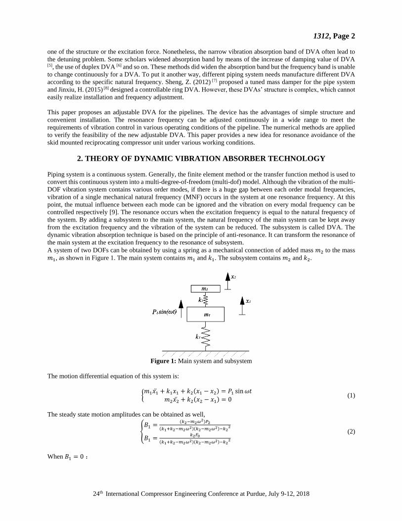
A system of two DOFs can be obtained by using a spring as a mechanical connection of added mass 𝑚2 to the mass
𝑚1, as shown in Figure 1. The main system contains 𝑚1 and 𝑘1. The subsystem contains 𝑚2 and 𝑘2.
Figure 1: Main system and subsystem
The motion differential equation of this system is:
{𝑚1𝑥1̈ + 𝑘1𝑥1 + 𝑘2(𝑥1 − 𝑥2) = 𝑃1 sin 𝜔𝑡
𝑚2𝑥2̈ + 𝑘2(𝑥2 − 𝑥1) = 0 (1)
The steady state motion amplitudes can be obtained as well,
{𝐵1 =
(𝑘2−𝑚2𝜔2)𝑃2
(𝑘1+𝑘2−𝑚2𝜔2)(𝑘2−𝑚2𝜔2)−𝑘22
𝐵1 =𝑘2𝐹0
(𝑘1+𝑘2−𝑚2𝜔2)(𝑘2−𝑚2𝜔2)−𝑘22
(2)
When 𝐵1 = 0 :
1312, Page 3
24th International Compressor Engineering Conference at Purdue, July 9-12, 2018
𝜔 = √𝑘2
𝑚2 (3)
Then, the original mass 𝑚1 no longer vibrates. This phenomenon is called anti-resonance. In other words, when the
natural frequency of the absorber is equal to the natural frequency of the main system, the effect of vibration
suppression is the best. The amplitude of the vibration absorber is 𝐵2 = −𝑃1/𝑘2 and the excitation force on the mass
is exactly balanced by the elastic restoring force of the spring from the absorber. The parameter of undamped DVA is
usually chosen as:
𝜇 =𝑚2
𝑚2=
𝑘2
𝑘1 (4)
Thus, the natural frequency of the absorber is equal to the natural frequency of the main system, and the original
resonance frequency, frequency ratio and static displacement of the primary system are recorded respectively𝜔0 =
√𝑘1/𝑚1 = √𝑘2/𝑚2, 𝜆 = 𝜔/𝜔0, 𝐵0 = 𝑃1/𝑘1. The dimensionless steady-state motion amplitudes of 𝑚1 and 𝑚2 are
as follow:
{
𝐵1
𝐵0=
1−𝜆2
𝜆4−(2+𝜇)𝜆2+1
𝐵1
𝐵0=
1
𝜆4−(2+𝜇)𝜆2+1
(5)
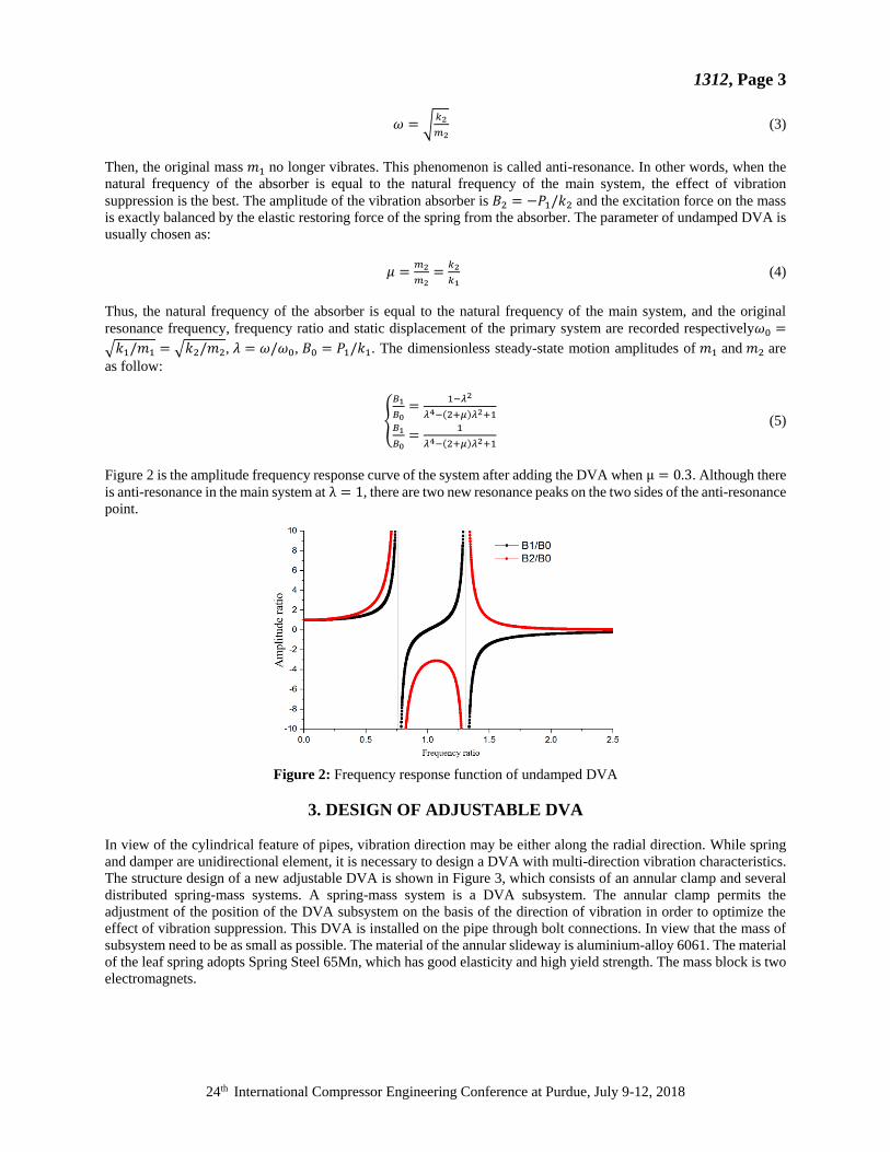
Figure 2 is the amplitude frequency response curve of the system after adding the DVA when μ = 0.3. Although there
is anti-resonance in the main system at λ = 1, there are two new resonance peaks on the two sides of the anti-resonance
point.
Figure 2: Frequency response function of undamped DVA
3. DESIGN OF ADJUSTABLE DVA
In view of the cylindrical feature of pipes, vibration direction may be either along the radial direction. While spring
and damper are unidirectional element, it is necessary to design a DVA with multi-direction vibration characteristics.
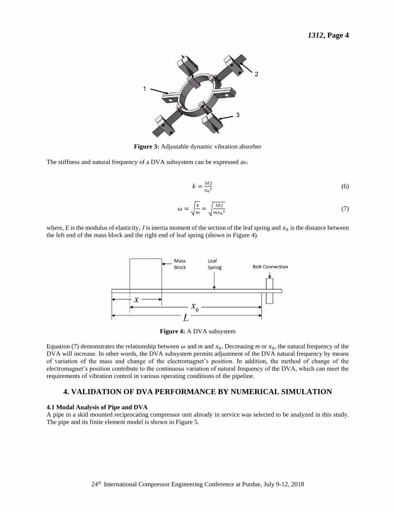
The structure design of a new adjustable DVA is shown in Figure 3, which consists of an annular clamp and several
distributed spring-mass systems. A spring-mass system is a DVA subsystem. The annular clamp permits the
adjustment of the position of the DVA subsystem on the basis of the direction of vibration in order to optimize the
effect of vibration suppression. This DVA is installed on the pipe through bolt connections. In view that the mass of
subsystem need to be as small as possible. The material of the annular slideway is aluminium-alloy 6061. The material
of the leaf spring adopts Spring Steel 65Mn, which has good elasticity and high yield strength. The mass block is two
electromagnets.
1312, Page 4
24th International Compressor Engineering Conference at Purdue, July 9-12, 2018
Figure 3: Adjustable dynamic vibration absorber
The stiffness and natural frequency of a DVA subsystem can be expressed as:
𝑘 =3𝐸𝐽
𝑥03 (6)
𝜔 = √𝑘
𝑚= √
3𝐸𝐽
𝑚𝑥03 (7)
where, E is the modulus of elasticity, J is inertia moment of the section of the leaf spring and 𝑥0 is the distance between
the left end of the mass block and the right end of leaf spring (shown in Figure 4).
Figure 4: A DVA subsystem
Equation (7) demonstrates the relationship between 𝜔 and m and 𝑥0. Decreasing m or 𝑥0, the natural frequency of the
DVA will increase. In other words, the DVA subsystem permits adjustment of the DVA natural frequency by means
of variation of the mass and change of the electromagnet’s position. In addition, the method of change of the
electromagnet’s position contribute to the continuous variation of natural frequency of the DVA, which can meet the
requirements of vibration control in various operating conditions of the pipeline.
4. VALIDATION OF DVA PERFORMANCE BY NUMERICAL SIMULATION
4.1 Modal Analysis of Pipe and DVA
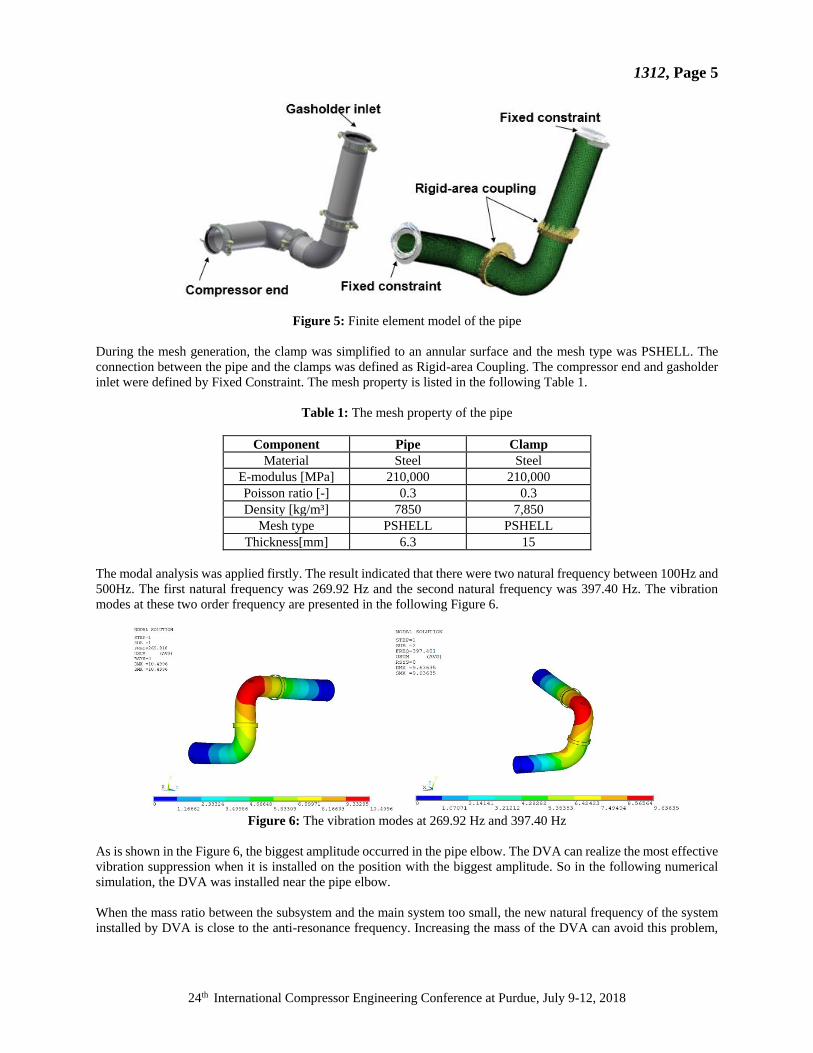
A pipe in a skid mounted reciprocating compressor unit already in service was selected to be analyzed in this study.
The pipe and its finite element model is shown in Figure 5.
1312, Page 5
24th International Compressor Engineering Conference at Purdue, July 9-12, 2018
Figure 5: Finite element model of the pipe
During the mesh generation, the clamp was simplified to an annular surface and the mesh type was PSHELL. The
connection between the pipe and the clamps was defined as Rigid-area Coupling. The compressor end and gasholder
inlet were defined by Fixed Constraint. The mesh property is listed in the following Table 1.
Table 1: The mesh property of the pipe
Component Pipe Clamp
Material Steel Steel
E-modulus [MPa] 210,000 210,000
Poisson ratio [-] 0.3 0.3
Density [kg/m³] 7850 7,850
Mesh type PSHELL PSHELL
Thickness[mm] 6.3 15
The modal analysis was applied firstly. The result indicated that there were two natural frequency between 100Hz and
500Hz. The first natural frequency was 269.92 Hz and the second natural frequency was 397.40 Hz. The vibration
modes at these two order frequency are presented in the following Figure 6.
Figure 6: The vibration modes at 269.92 Hz and 397.40 Hz
As is shown in the Figure 6, the biggest amplitude occurred in the pipe elbow. The DVA can realize the most effective
vibration suppression when it is installed on the position with the biggest amplitude. So in the following numerical
simulation, the DVA was installed near the pipe elbow.
When the mass ratio between the subsystem and the main system too small, the new natural frequency of the system
installed by DVA is close to the anti-resonance frequency. Increasing the mass of the DVA can avoid this problem,
1312, Page 6
24th International Compressor Engineering Conference at Purdue, July 9-12, 2018
but it will enhance the mass of the structure. The mass ration is usually about 1%. The mass of pipe selected is 40.66kg,
thus the mass of electromagnet was designed as 0.5kg.
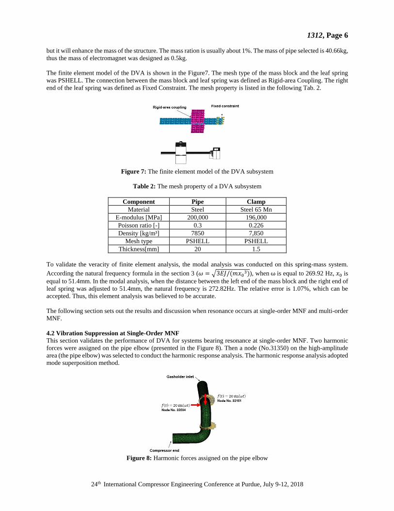
The finite element model of the DVA is shown in the Figure7. The mesh type of the mass block and the leaf spring
was PSHELL. The connection between the mass block and leaf spring was defined as Rigid-area Coupling. The right
end of the leaf spring was defined as Fixed Constraint. The mesh property is listed in the following Tab. 2.
Figure 7: The finite element model of the DVA subsystem
Table 2: The mesh property of a DVA subsystem
Component Pipe Clamp
Material Steel Steel 65 Mn
E-modulus [MPa] 200,000 196,000
Poisson ratio [-] 0.3 0.226
Density [kg/m³] 7850 7,850
Mesh type PSHELL PSHELL
Thickness[mm] 20 1.5
To validate the veracity of finite element analysis, the modal analysis was conducted on this spring-mass system.
According the natural frequency formula in the section 3 (𝜔 = √3𝐸𝐽/(𝑚𝑥03)), when ω is equal to 269.92 Hz, 𝑥0 is
equal to 51.4mm. In the modal analysis, when the distance between the left end of the mass block and the right end of
leaf spring was adjusted to 51.4mm, the natural frequency is 272.82Hz. The relative error is 1.07%, which can be
accepted. Thus, this element analysis was believed to be accurate.
The following section sets out the results and discussion when resonance occurs at single-order MNF and multi-order
MNF.
4.2 Vibration Suppression at Single-Order MNF
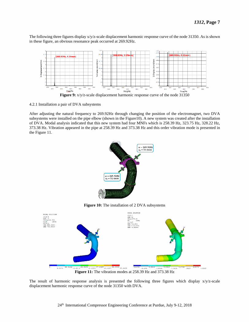
This section validates the performance of DVA for systems bearing resonance at single-order MNF. Two harmonic
forces were assigned on the pipe elbow (presented in the Figure 8). Then a node (No.31350) on the high-amplitude
area (the pipe elbow) was selected to conduct the harmonic response analysis. The harmonic response analysis adopted
mode superposition method.
Figure 8: Harmonic forces assigned on the pipe elbow
1312, Page 7
24th International Compressor Engineering Conference at Purdue, July 9-12, 2018
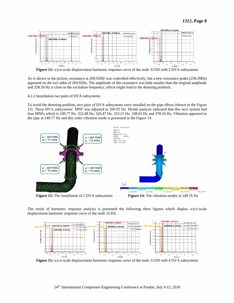
The following three figures display x/y/z-scale displacement harmonic response curve of the node 31350. As is shown
in these figure, an obvious resonance peak occurred at 269.92Hz.
Figure 9: x/y/z-scale displacement harmonic response curve of the node 31350
4.2.1 Installation a pair of DVA subsystems
After adjusting the natural frequency to 269.92Hz through changing the position of the electromagnet, two DVA
subsystems were installed on the pipe elbow (shown in the Figure10). A new system was created after the installation
of DVA. Modal analysis indicated that this new system had four MNFs which is 258.39 Hz, 323.75 Hz, 328.22 Hz,
373.38 Hz. Vibration appeared in the pipe at 258.39 Hz and 373.38 Hz and this order vibration mode is presented in
the Figure 11.
Figure 10: The installation of 2 DVA subsystems
Figure 11: The vibration modes at 258.39 Hz and 373.38 Hz
The result of harmonic response analysis is presented the following three figures which display x/y/z-scale
displacement harmonic response curve of the node 31350 with DVA.
1312, Page 8
24th International Compressor Engineering Conference at Purdue, July 9-12, 2018
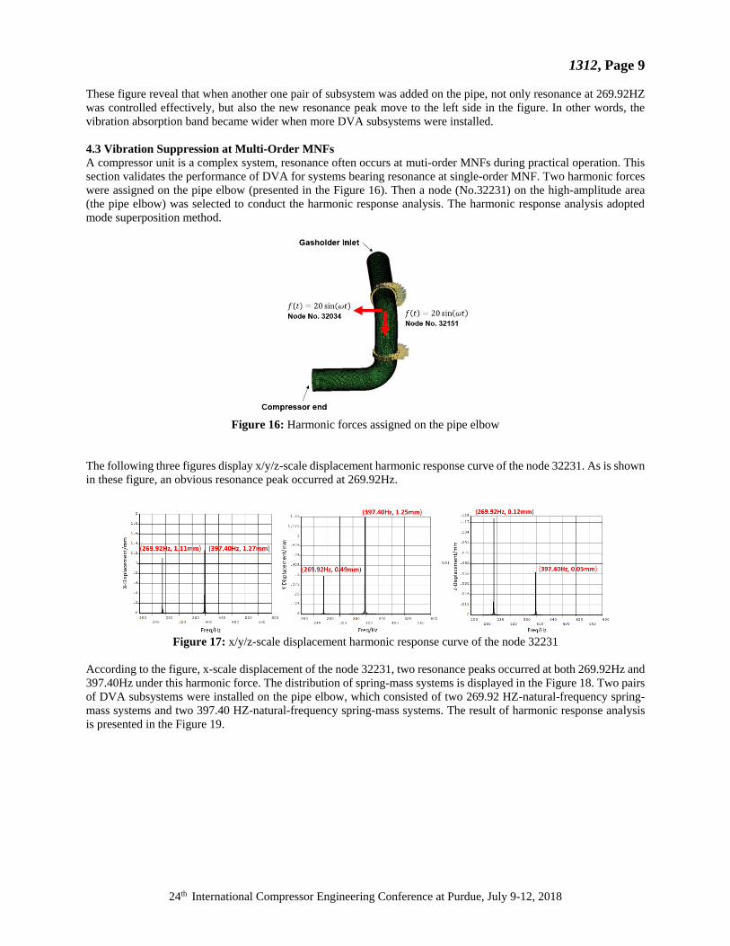
Figure 12: x/y/z-scale displacement harmonic response curve of the node 31350 with 2 DVA subsystems
As is shown in the picture, resonance at 269.92HZ was controlled effectively, but a new resonance peaks (258.39Hz)
appeared on the two sides of 269.92Hz. The amplitude of this resonance was little smaller than the original amplitude
and 258.39 Hz is close to the excitation frequency, which might lead to the detuning problem.
4.2.2 Installation two pairs of DVA subsystems
To avoid the detuning problem, two pairs of DVA subsystems were installed on the pipe elbow (shown in the Figure
13). These DVA subsystems’ MNF was adjusted to 269.92 Hz. Modal analysis indicated that this new system had
four MNFs which is 249.77 Hz, 322.68 Hz, 326.47 Hz, 333.21 Hz, 338.63 Hz and 378.16 Hz. Vibration appeared in
the pipe at 249.77 Hz and this order vibration mode is presented in the Figure 14.
Figure 13: The installation of 2 DVA subsystems Figure 14: The vibration modes at 249.76 Hz
The result of harmonic response analysis is presented the following three figures which display x/y/z-scale
displacement harmonic response curve of the node 31350.
Figure 15: x/y/z-scale displacement harmonic response curve of the node 31350 with 4 DVA subsystems
1312, Page 9
24th International Compressor Engineering Conference at Purdue, July 9-12, 2018
These figure reveal that when another one pair of subsystem was added on the pipe, not only resonance at 269.92HZ
was controlled effectively, but also the new resonance peak move to the left side in the figure. In other words, the
vibration absorption band became wider when more DVA subsystems were installed.
4.3 Vibration Suppression at Multi-Order MNFs
A compressor unit is a complex system, resonance often occurs at muti-order MNFs during practical operation. This
section validates the performance of DVA for systems bearing resonance at single-order MNF. Two harmonic forces
were assigned on the pipe elbow (presented in the Figure 16). Then a node (No.32231) on the high-amplitude area
(the pipe elbow) was selected to conduct the harmonic response analysis. The harmonic response analysis adopted
mode superposition method.
Figure 16: Harmonic forces assigned on the pipe elbow
The following three figures display x/y/z-scale displacement harmonic response curve of the node 32231. As is shown
in these figure, an obvious resonance peak occurred at 269.92Hz.
Figure 17: x/y/z-scale displacement harmonic response curve of the node 32231
According to the figure, x-scale displacement of the node 32231, two resonance peaks occurred at both 269.92Hz and
397.40Hz under this harmonic force. The distribution of spring-mass systems is displayed in the Figure 18. Two pairs
of DVA subsystems were installed on the pipe elbow, which consisted of two 269.92 HZ-natural-frequency spring-
mass systems and two 397.40 HZ-natural-frequency spring-mass systems. The result of harmonic response analysis
is presented in the Figure 19.

1312, Page 10
24th International Compressor Engineering Conference at Purdue, July 9-12, 2018
Figure 18: The installation of 4 DVA subsystems
Figure 19: x/y/z-scale displacement harmonic response curve of the node 32231 with DVA
As is shown in the figure, resonance at both 269.92Hz and 397.40Hz was controlled effectively. Therefore, for the
piping vibration simultaneously excited by multiple resonant frequencies, each-order-mode vibration can be
attenuated respectively through installing DVA subsystems which have different MNFs.
5. CONCLUSION
This study proposed an adjustable dynamic vibration absorber, consisting of an annular clamp and several distributed
spring-mass systems. Finite element analysis was used to validate the effect of vibration suppression. The main
conclusion are given below.
This DVA could suppress vibration effectively at original resonance frequency of the skid mounted
compressor unit without DVA.
Multiple distributed units of DVA subsystems in an annular clamp could obtain a much wider frequency
band, which overcame the defect that two resonance peaks appeared after installing the traditional DVA.
Equipped with multiple sets of DVA subsystems with different natural frequencies, this DVA had an
effective vibration attenuation for the system bearing resonance at multi-order MNFs.
REFERENCES
[1] Ejun, X. (1994). Preliminary on Aero Engine Duct Structural Integrity Requirements. Aeroengine, 1994(3), 53-
62.
[2] Wei, L., Gang, G. & Hong, Z. (2012).Sensitivity analysis and dynamic optimization design of support’s postion
for engine pipelines. Journal of Aerospace Power, 27(12), 2756-2762.
[3] Ormondroyd, D. H. (1928). The theory of the dynamic vibration absorber. J. Trans ASME, 50(7).
[4] Brock, J. E. (1946). A note on the damped vibration absorber, trans. ASME. Journal of Applied Mechanics, A-
284.
[5] Xiao, H. L. & He, L. (2002). A simulation design for the vibration absorber. Ship & Ocean Engineering,
2002(5), 21-23.
[6]Cheung, Y. L. &Wang, W. O. (2011). H-infinity optimization of a variantdesign of the dynamic vibration
absorber—revisited and new results. Journal of Sound and Vibration, 330(16), 3901-3912.
1312, Page 11
24th International Compressor Engineering Conference at Purdue, July 9-12, 2018
[7]Sheng, Z., Yi, R. & Taotao, C. (2012). Vibration suppression of pipe system with tuned mass damper. Journal of
Vibration, Measurement & Diagnosis, 32(5), 823-826.
[8]Jinxiu, H., Lidong, H. & Chenyang, W. (2015). Reduction in forced vibration of a pipe by means of a controllable
ring dynamic vibration absorber. Journal of Beijing University of Chemical Technology (Natural Science), 42(3),
89-93.
[9]Zhenhua, N. (1989). Vibration mechanics. Xi’an, Xi’an.Jiaotong University Publishers.