Embed Size (px)
Citation preview

1
The Design and Use of OhmegaPly®
Embedded Resistors for Series and Parallel Termination
By
Bruce Mahler
Vice President
Ohmega Technologies, Inc.
Introduction
The OhmegaPly® Embedded Thin-Film Resistor Material has been used since the early 1970’s as
terminating resistors in a variety of electronic systems. Through generations of digital designs,
the shape, size and layout of the terminating resistors has evolved to meet the demands of
increased IC density and the changing packaging architectures. This paper will review some of
the earlier applications of OhmegaPly terminating resistors and describe the improvements made
in the material to meet today’s demanding requirements for high density PCB termination.
Proper signal-line termination reduces signal reflection, increases speed and performance and
improves signal integrity. This is critical for high speed digital signals as it reduces trace, pad
and via impedance and via stubs. (1)

2
OhmegaPly embedded terminating resistors can be placed very close to the end of the driveline,
improving impedance matching and reducing line delay. Fig 1 and Fig 2 show typical design
layouts for both series and parallel termination using OhmegaPly as embedded resistors in
multilayer circuit boards. Unterminated drivelines and stubs are also reduced or eliminated
and the inductive reactance is lowered when compared to discrete resistors. This is critical as the
inductance of chip resistors combined with via inductance can seriously impact cross-talk as well
as the leading edge of the high speed signal (2).
Design and Use of OhmegaPly Termination Resistors
OhmegaPly was used for terminating resistors in 1973 in the Tektronix 21 and Tektronix 31 desk
top programmable calculators. The terminating resistor network was used at the end of a
connecting cable that tied peripherals to the calculator. The resistor network consisted of forty-
four 120 ohm value resistors. Twenty-two resistors were on each side of a rigid double-sided
Figure 2. Series terminating resistorsFigure 1. Parallel terminating resistors

3
FR4 substrate. OhmegaPly 25 ohm per square sheet resistivity product was used and the resistor
dimensions were approximately 60 mils wide and 290 mils long (3).
A more sophisticated use of OhmegaPly for terminating resistors occurred a year later in 1974.
Control Data’s Aerospace (Military) group designed 100 ohm per square OhmegaPly into a
multilayer board as parallel terminating resistors for ECL logic devices (Fig 3). The resistor
design (Fig 4) had two elements in parallel extending from a common via. A 50 ohm value
resistor was created by paralleling two-100 ohm value resistors and a 75 ohm value resistor was
created by paralleling two-150 ohm value resistors. Although this basic design was used on a
number of part numbers, ultimately the design was changed to one resistor element using 25 ohm
per square material in order to use less area for the terminating resistor footprint. Further
generations of Cyber systems continued to use OhmegaPly for ECL logic termination. The use of
OhmegaPly for ECL terminating resistors migrated to Control Data’s commercial mainframe
group and was designed into the Cyber 203 and Cyber 205 (4).
Figure 3. Control Data PCB Board
Copper pad
Figure 4. A 75 ohm value made using 2- 150 ohm parallel resistors
Resistor element
Voltage plane
4
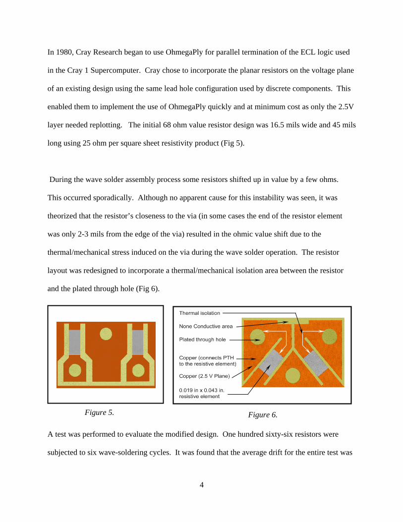
In 1980, Cray Research began to use OhmegaPly for parallel termination of the ECL logic used
in the Cray 1 Supercomputer. Cray chose to incorporate the planar resistors on the voltage plane
of an existing design using the same lead hole configuration used by discrete components. This
enabled them to implement the use of OhmegaPly quickly and at minimum cost as only the 2.5V
layer needed replotting. The initial 68 ohm value resistor design was 16.5 mils wide and 45 mils
long using 25 ohm per square sheet resistivity product (Fig 5).
During the wave solder assembly process some resistors shifted up in value by a few ohms.
This occurred sporadically. Although no apparent cause for this instability was seen, it was
theorized that the resistor’s closeness to the via (in some cases the end of the resistor element
was only 2-3 mils from the edge of the via) resulted in the ohmic value shift due to the
thermal/mechanical stress induced on the via during the wave solder operation. The resistor
layout was redesigned to incorporate a thermal/mechanical isolation area between the resistor
and the plated through hole (Fig 6).
A test was performed to evaluate the modified design. One hundred sixty-six resistors were
subjected to six wave-soldering cycles. It was found that the average drift for the entire test was
Figure 5. Figure 6.

5
only +0.3 ohm with a maximum drift of +1 ohm. (Table 1) (5).
Following generations of Cray Supercomputers (Cray XMP, Cray YMP, Cray 2) used
OhmegaPly resistors with a thermal/mechanical connection of about 10-20 mils between the
termination resistor and the via. With the advent of HDI and microvia technology, current
recommendations are to use an approximately 10 mil connection of copper for mechanically
drilled via’s and approximately 5 mils for laser drilled microvias for thermal/mechanical
stability. (Fig 7)
In the 1990’s, the basic design of the OhmegaPly terminating resistors remained the same while
Table 1.
4.5
4.0
3.5
3.0
2.5
2.0
1.5
1.0
0.5
0
0 1 wavecycle
3 wavecycle
6 wavecycle
1 hand soldering
Averagedrift (
)
Initial resistor design Modified resistor design
Figure 7.

6
application of the Technology began to grow, especially by Computer and Telecommunications
companies. Some of the users were Harris (6), Sun Microsystems, Prime Computer, Data
General, Wang, Sequent, IBM and Alcatel (7).
Greater I/O densities and the use of BGA packages became common within the Electronics
Packaging Industry. The space constraints of these packages generated growing interest in
embedded termination resistors. Standard thin film design rules created resistors that were either
partial squares, squares or multiple squares of resistive material.
A study was done in 1995 to evaluate the stability of various alternative resistor footprints for
BGA termination (8). A four layer FR4 test board was built with these designs incorporated into
the voltage plane (layer 2) in a parallel termination scheme (Fig 8). This was done to aid in the
testing of the embedded resistors, with one side of each resistor tied to the common voltage
plane.
Figure 8.

7
The resistor designs included rectangular (Fig 9) and circular resistors (Fig 10).
Subsequent testing of the resistors showed that the rectangular-shaped resistors had better
stability than circular resistors when subjected to a variety of environmental conditions (Table 2).
Table 2. Percent increase in resistance value
Although a number of factors contribute to resistor stability, it was speculated that circular
resistors are subject to greater physical stress than rectangular resistors due to their proximity to
Figure 9. Figure 10.
Resistor elements
Copper
Test condition Rectangular Circular Circular Circular
50 11 30 110
1) Short term load 700 mW 500 mW 350 mW 350 mW
testing
2) Solder float 0.15% 0.30% 0.90% 0.75%
260 °C , 20 sec per
cycle. 4 cycles
3) Humidity test 0.20% 0.30% 0.75% 0.65%
240 hrs. at 95%
RH 40 °C
4) Life operating, 0.10% 0.80% 1.25% 1.80%
26mW, 45 °C
ambient 1,000 hrs.

8
the interconnect via. The dynamic movement, or stress, of the PCB in the X, Y and especially Z
axis is greatest around the plated through via. This stress is most pronounced during thermal and
humidity excursions where the expansion rates of the dielectric material, inner layer copper
planes and plated through copper vias cause mismatched material movements. Further, the heat
distribution (and power density) of a circular resistor under load is not uniform as the heat is
concentrated in the inner area of the resistor, near the via.
As the embedded resistor footprints became smaller and more narrow it was important to
determine how much the smaller size and narrower width limited the current carrying capacity as
well as their susceptibility to electrostatic discharge (ESD). In 2001, Delphi Delco Electronics
Systems tested a number of new and developmental thin and thick film resistive materials for
susceptibility to ESD. OhmegaPly was selected for use as the benchmark material because of its
history of reliability and thermal and electrical stability. OhmegaPly was found to be ESD stable
throughout the voltage range from 2 kV to 8 kV and resistors widths as narrow as 10 mils. It
was the only thin film resistive material to pass this test. OhmegaPly is typically 4-10 times
thicker than other thin film resistive alloys of similar sheet resistivities. This results in greater
power carrying capability and a greater stability in ESD testing (9).
A study was done in 2001 to determine the effect of miniaturization on embedded terminating
resistors relative to their rated power. It found that 16 mil wide resistors were able to dissipate
between 200 and 300 milliwatts at 40C. Since terminating resistors operated well below this

9
power, it was determined that much narrower resistor widths could be used. Resistor widths of
10 mils became a common Industry practice (10).
The evolution to greater I/O densities and routing constrictions made it very difficult, if not
impossible, to embed termination resistors in the logic plane of the PCB under the BGA package.
Clearly another strategy needed to be employed.
In 2004 Ohmega Technologies, Inc. developed a new product, ORBIT®, specifically to meet this
challenge. ORBIT was a ten ohm per square sheet resistivity thin film material which allowed
termination resistors to be built within traces and eliminated the requirement for designing a
resistor footprint and placing them within the circuit layout (11) (Fig 11).
Figure 11.

10
Because ORBIT was much thicker than other OhmegaPly sheet resistivites, its power dissipation
was greater, about 25% more than 25 ohm per square material (Table 3).
ORBIT also had a tighter material tolerance than the higher sheet resistivity products--3% versus
5% for 25 – 100 ohm per square sheet resistivities. These were critical parameters for the
formation of very small resistor elements that could handle the rated power and tolerances
required for termination resistors. The ORBIT product was processed like the other OhmegaPly
sheet resistivity products. Since the resistors were built within the trace, any board shop with the
capability of building controlled impedance traces could build ORBIT termination resistors.
Currently, the ORBIT technology for series termination resistors is used by a number of
computer, medical and telecommunications equipment manufacturers. Other applications for
ORBIT have also become popular, especially as heater elements in flexible circuits
(OhmegaFlex® heaters) and in R-Card arrays for military/aerospace applications.
Table 3.
y = 192.2x-0.87
y = 153.7x-0.87
y = 136.8x-0.87
y = 115.3x-0.87
y = 100.0x-0.87
0
200
400
600
800
1000
1200
1400
1600
1800
0.00 0.10 0.20 0.30 0.40 0.50 0.60 0.70
Pow
er D
ensi
ty (m
W/m
m2 )
Resistor Area (mm2)
POWER DENSITY OF 10-250 OHM/SQ. MATERIAL VERSUS DIFFERENT RESISTOR AREA AT 25 °C AMBIENT
10 ohm/sq.
25 ohm/sq.
50 ohm/sq.
100 oh/sq.
250 ohm/sq.

11
Greater circuit densities and smaller feature sizes have driven ORBIT termination resistors to
even smaller dimensions. Resistor widths of 3 mils and less are not unheard of. In order to
maintain acceptable resistor tolerances, state of the art imaging and etching has become more
popular, in particular with the use of LDI (Laser Direct Imaging). LDI has the advantage of
allowing for near perfect registration for the second imaging that defines the resistor length. This
means that the overlap of photoresist can be smaller and resistors can be placed closer to other
circuit layer features (Fig 12).
Figure 12.

12
One current application for OhmegaPly ORBIT requires small element sizes (6 mil wide x 10
mil long) on an inner layer of a relatively large circuit board (14” x 15”). These resistors have a
rated power of 125 mW. The unique design requires 3 resistor elements in series (Fig. 13).
Figure 13.
The board shop manufacturing these boards is achieving close to a 100% OhmegaPly resistor
layer production yield for this application with a resistor tolerance requirement of +/- 10%.
Both the first image (defining the resistor width) and second image (defining the resistor length)
are done using LDI.

13
Summary
After decades of excellent performance within critical military/aerospace applications (satellites,
fighter aircraft, missiles, control circuits) OhmegaPly remains the embedded material of choice
for most termination requirements. Currently OhmegaPly is being used for termination
requirements in a broad and diverse number of applications including space exploration,
telecommunications, cellular, medical and industrial electronics.
REFERENCES
1. Mai Vu, “Choose Termination and Topology to Maximize Signal Integrity and Timing”, EDN Magazine, October 24, 1996.
2. Bruce Mahler, “Planar Resistor Technology”, Printed Circuit Fabrication, Vol. 5 No. 9, September 1982.
3. Al Ertel, “Resistor-Conductor Laminates: A Ceramic Substrate Alternative”, Electronic Packaging and Production, October 1973, pp. 159-161.
4. Jeff Bohn, “Packaging High-Power LSI Devices in High-Speed Computer Systems”, Electronic Packaging and Production, 1981.
5. Paul Schroeder and Bruce Mahler, “Planar Resistor Technology for High-Speed Multilayer Boards”, Electronic Packaging and Production, January 1986.
6. Don Noel, “Harnessing Design Automation in PCBs”, Design News, March 15, 1985, pp 163-167.
7. Joris Peeters, Annj Ackaert, Louis Vandam, Koen Allaert, Marnix Botte, Luc Van Den Torren, Luc Martens and Daniel De Zutter, “Characterization in Integrated Resistors for Broadband Telecom Printed Circuit Boards”, IPC World Expo, June 1996.
8. Bruce Mahler, “BGA Termination Alternatives”, Electronic Packaging and Production, February 1996, pp 71-74.

14
9. Jiming Zhou, Johm D. Meyers, and Graeme R. Dickinson, “Thermal Cycling and ESD
Evaluation of Embedded Resistors and Capacitors in PWB”, IPC Technical Conference, October 2001.
10. Daniel D. Brandler, “The Effect of Miniaturization on Embedded Resistors in High Density Interconnecting Substrates”, International symposium on Microelectronics, 2001.
11. Bruce P. Mahler, “Embedding Thin-Film Resistors In Advanced PWBs”, OnBoard Technology, April 2004, pp 10-13.
OhmegaPly®, OhmegaFlex® and ORBIT® are Registered Trademarks of Ohmega Technologies, Inc. Culver City, CA 90232