Embed Size (px)
Citation preview
0093-9994 (c) 2017 IEEE. Personal use is permitted, but republication/redistribution requires IEEE permission. See http://www.ieee.org/publications_standards/publications/rights/index.html for more information.
This article has been accepted for publication in a future issue of this journal, but has not been fully edited. Content may change prior to final publication. Citation information: DOI 10.1109/TIA.2017.2754983, IEEETransactions on Industry Applications
1
Design and Performance Analysis of Three-PhaseSolar PV Integrated UPQC
Sachin Devassy, Member, IEEE and Bhim Singh, Fellow, IEEE
Abstract—This paper deals with the design and performanceanalysis of a three-phase single stage solar photovoltaic in-tegrated unified power quality conditioner (PV-UPQC). ThePV-UPQC consists of a shunt and series connected voltagecompensators connected back to back with common DC-link.Theshunt compensator performs the dual function of extractingpower from PV array apart from compensating for load currentharmonics. An improved synchronous reference frame controlbased on moving average filter is used for extraction of loadactive current component for improved performance of the PV-UPQC. The series compensator compensates for the grid sidepower quality problems such as grid voltage sags/swells. Thecompensator injects voltage in-phase/out of phase with point ofcommon coupling (PCC) voltage during sag and swell conditionsrespectively. The proposed system combines both the benefitsof clean energy generation along with improving power quality.The steady state and dynamic performance of the system areevaluated by simulating in Matlab-Simulink under a nonlinearload. The system performance is then verified using a scaleddown laboratory prototype under a number of disturbances suchas load unbalancing, PCC voltage sags/swells and irradiationvariation.
Index Terms—Power Quality, shunt compensator, series com-pensator, UPQC, Solar PV, MPPT.
I. INTRODUCTION
With the advancement in semiconductor technology, there isan increased penetration of power electronic loads. These loadssuch as computer power supplies, adjustable speed drives,swtiched mode power supplies etc. have very good efficiency,however, they draw nonlinear currents. These nonlinear cur-rents cause voltage distortion at point of common couplingparticularly in distribution systems. There is also increasingemphasis on clean energy generation through installation ofrooftop PV systems in small apartments as well as in com-mercial buildings [1], [2]. However, due to the intermittentnature of the PV energy sources, an increased penetrationof such systems, particularly in weak distribution systemsleads to voltage quality problems like voltage sags and swells,which eventually instability in the grid [3]–[7]. These voltagequality problems also lead to frequent false tripping of powerelectronic systems, malfunctioning and false triggering ofelectronic systems and increased heating of capacitor banksetc [8]–[10]. Power quality issues at both load side and gridside are major problems faced by modern distribution systems.
Due to the demand for clean energy as well as stringentpower quality requirement of sophisticated electronic loads,there is need for multifunctional systems which can integrateclean energy generation along with power quality improve-ment. A three phase multi-functional solar energy conversionsystem, which compensates for load side power quality issues
has been proposed in [11], [12]. A single phase solar pvinverter along with active power filtering capability has beenproposed in [13], [14]. Major research work has been donein integrating clean energy generation along with shunt activefiltering. Though shunt active filtering has capability for bothload voltage regulation, it comes at the cause of injectingreactive power. Thus shunt active filtering cannot regulatePCC voltage as well as maintain grid current unity powerfactor at same time. Recently, due to the stringent voltagequality requirements for sophsiticated electronics loads, theuse of series active filters has been proposed for use insmall apartments and commercial buildings [15], [16]. A solarphotovoltaic system integrated along with dynamic voltagerestorer has been proposed in [17]. Compared to shunt andseries active power filters, a unified power quality conditioner(UPQC), which has both series and shunt compensators canperform both load voltage regulation and maintain grid currentsinusoidal at unity power factor at same time. IntegratingPV array along with UPQC, gives the dual benefits of cleanenergy generation along with universal active. The integrationof PV array with UPQC has been reported in [18]–[20].Compared to conventional grid connected inverters, the solarPV integrated UPQC has numerous benefits such as improvingpower quality of the grid, protecting critical loads from gridside disturbances apart from increasing the fault ride throughcapability of converter during transients. With the increasedemphasis on distributed generation and microgrids, there is arenewed interest in UPQC systems [21], [22].
Reference signal generation is a major task in control of PV-UPQC. Reference signal generation techniques can be broadlydivided into time-domain and frequency domain techniques[8]. Time domain techniques are commonly used because oflower computational requirements in real-time implementa-tion. The commonly used techniques include instantaneousreactive power theory (p-q theory), synchronous referenceframe theory (d-q theory) and instantaneous symmetrical com-ponent theory [23]. The main issue in use of synchronousreference frame theory based method is that during loadunbalanced condition, double harmonic component is presentin the d-axis current. Due to this, low pass filters with verylow cut off frequency is used to filter out double harmoniccomponent. This results in poor dynamic performance [24]. Inthis work, a moving average filter (MAF) is used to filter thed-axis current to obtain fundamental load active current. Thisgives optimal attenuation and without reducing the bandwidthof the controller [25]. Recently, MAF has been applied inimproving performance of DC-link controllers as well as forgrid synchronization using phase locked loop (PLL). [26],
0093-9994 (c) 2017 IEEE. Personal use is permitted, but republication/redistribution requires IEEE permission. See http://www.ieee.org/publications_standards/publications/rights/index.html for more information.
This article has been accepted for publication in a future issue of this journal, but has not been fully edited. Content may change prior to final publication. Citation information: DOI 10.1109/TIA.2017.2754983, IEEETransactions on Industry Applications
2
[27].In this paper, the design and performance analysis of a three-
phase PV-UPQC are presented. An MAF based d-q theorybased control is used to improve the dynamic performanceduring load active current extraction. The main advantages ofthe proposed system are as follows,
• Integration of clean energy generation and power qualityimprovement.
• Simultaneous voltage and current quality improvement.• Improved load current compensation due to use of MAF
in d-q control of PV-UPQC.• Stable under various dynamic conditions of voltage
sags/swells, load unbalance and irradiation variation.The performance of the proposed system is analyzed exten-sively under both dynamic and steady state conditions usingMatlab-Simulink software. The performance is then experi-mentally verified using a scaled down laboratory prototypeunder various conditions experienced in the distribution systemsuch as voltage sags/swells, load unbalance and irradiationvariation.
II. SYSTEM CONFIGURATION AND DESIGN
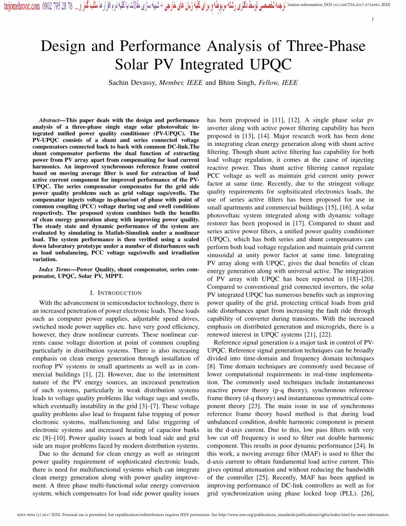
The structure of the PV-UPQC is shown in Fig.1. ThePV-UPQC is designed for a three-phase system. The PV-UPQC consists of shunt and series compensator connectedwith a common DC-bus. The shunt compensator is connectedat the load side. The solar PV array is directly integratedto the DC-link of UPQC through a reverse blocking diode.The series compensator operates in voltage control modeand compensates for the grid voltage sags/swells. The shuntand series compensators are integrated to the grid throughinterfacing inductors. A series injection transformer is usedto inject voltage generated by the series compensator into thegrid. Ripple filters are used to filter harmonics generated dueto switching action of converters. The load used is a nonlinearload consisting of a bridge rectifier with a voltage-fed load.
3-Phase
Nonlinear
Load
PV
Array
Lr
Lr
Lr
Cr
Lf
Lf
Cr
Cr Rr
Rr
Rr
Lf
Cf Rf
vsavMa
isa
vsb
vsc
isb
isc
VSEb
VSEc
VSEa
vMb
vMc
iLa
iLb
iLc
vLa
vlb
vlc
iSHa
iSHb
iSHc
Cpv
Cf
Cf
Rf
Rf
Cdc
Ls Rs
Ls Rs
Ls Rs
ipv
vDCvpv
Series compensator Shunt Compensator
Fig. 1. System Configuration PV-UPQC
A. Design of PV-UPQC
The design procedure for PV-UPQC begins with the propersizing of PV array, DC-link capacitor, DC-Link voltage leveletc. The shunt compensator is sized such that it handles thepeak power output from PV array apart from compensating forthe load current reactive power and current harmonics. As thePV array is directly integrated to the DC-link of UPQC, the PVarray is sized such that the MPP voltage is same as desired DC-link voltage. The rating is such that, under nominal conditions,the PV array supplies the load active power and also feedspower into the grid. The detailed PV array specifications aregiven in Appendix A. The other designed components are theinterfacing inductors of series and shunt compensators andseries injection transformer of the series compensator. Thedesign of PV-UPQC is elaborated as follows.
1) Voltage Magnitude of DC-Link: The magnitude of DC-link voltage Vdc depends on the depth of modulation usedand per-phase voltage of the system. The DC-link voltagemagnitude should more than double the peak of per-phasevoltage of the three phase system [8] and is given as,
Vdc =2√2VLL√3m
(1)
where depth of modulation (m) is taken as 1 and VLL is thegrid line voltage. For a line voltage of 415 V, the requiredminimum value DC-bus voltage is 677.7 V. The DC-busvoltage is set at 700 V(approx), which is same as the MPPToperating voltage of PV array at STC conditions.
2) DC-Bus Capacitor Rating: The DC-link capacitor issized based upon power requirement as well as DC-bus voltagelevel. The energy balance equation for the DC-bus capacitoris given as follows [8],
Cdc =3kaVphIsht
0.5× (V 2dc − V 2
dc1)
=3× 0.1× 1.5× 239.6× 34.5× 0.03
0.5× (7002 − 677.792)
= 9.3mF (2)
where Vdc is the average DC-bus voltage, Vdc1 is the lowestrequired value of DC-bus voltage,a is the overloading factor,Vph is per-phase voltage, t is the minimum time required forattaining steady value after a disturbance, Ish is per-phasecurrent of shunt compensator, k factor considers variation inenergy during dynamics.
The minimum required DC-link voltage is Vdc1 = 677.69 Vas obtained from (2), Vdc = 700 V, Vph= 239.60 V,Ish=57.5A, t= 30 ms, a = 1.2, and for dynamic energy change = 10%,k= 0.1, the value of Cdc is obtained as 9.3 mF.
3) Interfacing Inductor for Shunt Compensator: The in-terfacing inductor rating of the shunt compensator dependsupon the ripple current, the switching frequency and DC-linkvoltage. The expression for the interfacing inductor is as,
Lf =
√3mVdc
12afshIcr,pp=
√3× 1× 700
12× 1.2× 10000× 6.9
= 800μH ≈ 1mH (3)
0093-9994 (c) 2017 IEEE. Personal use is permitted, but republication/redistribution requires IEEE permission. See http://www.ieee.org/publications_standards/publications/rights/index.html for more information.
This article has been accepted for publication in a future issue of this journal, but has not been fully edited. Content may change prior to final publication. Citation information: DOI 10.1109/TIA.2017.2754983, IEEETransactions on Industry Applications
3
where m is depth of modulation, a is pu value of maximumoverload, fshis the switching frequency , Icr,pp is the inductorripple current which is taken as 20% of rms phase current ofshunt compensator. Here, m=1, a=1.2, fsh=10kHz, Vdc=700V,one gets 800 μH as value. The value chosen is approximatedto 1mH.
4) Series Injection Transformer: The PV-UPQC is designedto compensate for a sag/swell of 0.3 pu i.e 71.88 V. Hence, therequired voltage to be injection is only 71.88 V which resultsin low modulation index for the series compensator whenthe DC-link voltage is 700V. In order to operate the seriescompensator with minimum harmonics, one keeps modulationindex of the series compensator near to unity. Hence a seriestransformer is used with a turns ratio,
KSE =VV SC
VSE= 3.33 ≈ 3 (4)
The value obtained for KSE is 3.33. The value selected is 3.The rating of series injection transformer is given as,
SSE = 3VSEISEsag = 3× 72× 46 = 10kV A (5)
The current through series VSC is same as grid current.The supply current under sag condition of 0.3 pu is 46 A andhence the VA rating of injection transformer achieved is 10kVA.
5) Interfacing Inductor of Series Compensator: The ratingof interfacing inductor of the series compensator depends onripple current at swell condition, switching frequency and DC-link voltage. Its value is expressed as,
Lr =
√3×mVdcKSE
12afseIr=
√3× 1× 700× 3
12× 1.2× 10000× 7.1
= 3.6mH (6)
where m is the depth of modulation, a is the pu value ofmaximum overload, fse is the switching frequency, Ir is theinductor current ripple, which is taken to be 20% of gridcurrent. Here, m=1, a=1.5, fse=10 kHz, Vdc=700 V and 20%ripple current, one gets 3.6 mH as selected value.
III. CONTROL OF PV-UPQCThe main subsystems of PV-UPQC are the shunt com-
pensator and the series compensator. The shunt compensatorcompensates for the load power quality problems such as loadcurrent harmonics and load reactive power. In case of PV-UPQC, the shunt compensator performs the additional functionof supplying power from the solar PV array. The shuntcompensator extracts power from the PV-array by using amaximum power point tracking (MPPT) algorithm. The seriescompensator protects the load from the grid side power qualityproblems such as voltage sags/swells by injecting appropriatevoltage in phase with the grid voltage.
A. Control of Shunt Compensator
The shunt compensator extracts the maximum power fromthe solar PV-array by operating it at its maximum powerpoint. The maximum power point tracking (MPPT) algorithmgenerates the reference voltage for the DC-link of PV-UPQC.
Some of the commonly used MPPT algorithms [28] are Per-turb and Observe (P& O) algorithm, incremental conductancealgorithm (INC). In this work, (P& O) algorithm is used forimplementing MPPT. The DC-link voltage is maintained atthe generated reference by using a PI-controller.
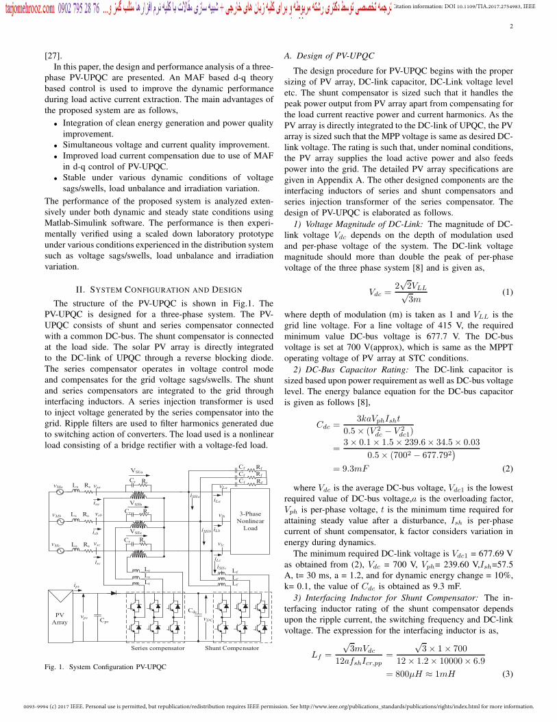
To perform the load current compensation, the shunt com-pensator extracts the active fundamental component of the loadcurrent. For this work, the shunt compensator is controlled byextracting fundamental active component of load current usingSRF technique. The control structure of shunt compensator isshown in Fig. 2. The load currents are converted to d-q-0 do-main using the phase and frequency information obtained fromPLL. The PLL input is the PCC voltage. The d-componentof the load current (ILd) is filtered to extract DC component(ILdf ) which represents the fundamental component in abcframe of reference. To extract DC component without dete-riorating the dynamic performance, a moving average filter(MAF) is used to extract the DC component. The transferfunction of moving average filter is given as,
MAF (s) =1− e−Tws
Tws(7)
where Tw is the window length of the moving average filter.As the lowest harmonic present in the d-axis current is doubleharmonic component, Tw is kept at half of fundamental timeperiod. The MAF has unity DC gain and zero gain integermultiples of window length.
The equivalent current component due to PV array is givenas,
Ipvg =2
3
Ppv
Vs(8)
where Ppv is the PV array power and Vs is the magnitude ofthe PCC voltage. The reference grid current in d-axis is givenas
I∗sd = ILdf + Iloss − Ipvg (9)
I∗sd is converted to abc domain reference grid currents. Thereference grid currents are compared with the sensed gridcurrents in a hysteresis current controller to generate the gatingpulses for the shunt converter.
PLL
vsabc
Vpv
Vdc
PI
iLa
iLb
iLc
abc
dq0
ILd Moving
Average
Filter
++
Iloss abc
dq0
Isq*=0 I0
*=0
Hysteresis
Current
Controller
isa* isb
* isc*
isa
isb
isc
Gating Pulses
3-LEG VSI
cos ,sin� �
+ _Ipv
Vdc*
MPPT
Moving
Average
Filter
ILdf
Ppv
Vs�
2
3
Ipvg
-
cos ,sin� �
Isd*
Fig. 2. Control Structure of Shunt Compensator
0093-9994 (c) 2017 IEEE. Personal use is permitted, but republication/redistribution requires IEEE permission. See http://www.ieee.org/publications_standards/publications/rights/index.html for more information.
This article has been accepted for publication in a future issue of this journal, but has not been fully edited. Content may change prior to final publication. Citation information: DOI 10.1109/TIA.2017.2754983, IEEETransactions on Industry Applications
4
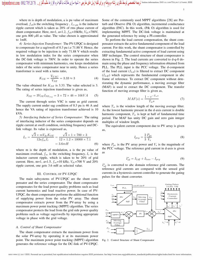
B. Control of Series CompensatorThe control strategy for the series compensator are pre-
sag compensation, in-phase compensation and energy optimalcompensation. A detailed description of various compensationstrategies used for control of series compensator is reportedin [29], [30] In this work, the series compensator injectsvoltage in same phase as that of grid voltage, which resultsin minimum injection voltage by the series compensator. Thecontrol structure of the series compensator is shown in Fig.3.The fundamental component of PCC voltage is extracted usinga PLL which is used for generating the reference axis in d-q-0 domain. The reference load voltage is generated usingthe phase and frequency information of PCC voltage obtainedusing PLL. The PCC voltages and load voltages are convertedinto d-q-0 domain. As the reference load voltage is to be inphase with the PCC voltage, the peak load reference voltageis the d-axis component value of load reference voltage. Theq-axis component is kept at zero. The difference betweenthe load reference voltage and PCC voltage gives the ref-erence voltage for the series compensator. The differencebetween load voltage and PCC voltage gives the actual seriescompensator voltages. The difference between reference andactual series compensator voltages is passed to PI controllersto generate appropriate reference signals. These signals areconverted to abc domain and passed through pulse widthmodulation (PWM) voltage controller to generate appropriategating signals for the series compensator.
abc
dq0
PLL
abc
dq0
Vsa
Vsb
Vsc
VLa
VLb
VLc
_+
_+
_+
_+
Vsd
Vsq
VLq
VLd _+
_+
VLq*=0VLd
*
abc
dq0
PI
PI
PWM Voltage
Controller
VSEa*
VSEb* VSEc
*
Gate Pulses
Series VSC
cos ,sin� �
cos ,sin� �
cos ,sin� �
VSEd*VSEq
*
Fig. 3. Control Structure of Series Compensator
IV. SIMULATION STUDIES
The steady state and dynamic performances of PV-UPQCare analyzed by simulating the system in Matlab-Simulinksoftware. The load used is a nonlinear load consisting of threephase diode bridge rectifier with R-L load. The solver stepsize used for the simulation is 1e-6s. The system is subjectedto various dynamic conditions such as sag and swell in PCCvoltage and PV irradiation variation. The detailed systemparameters are given in Appendix.
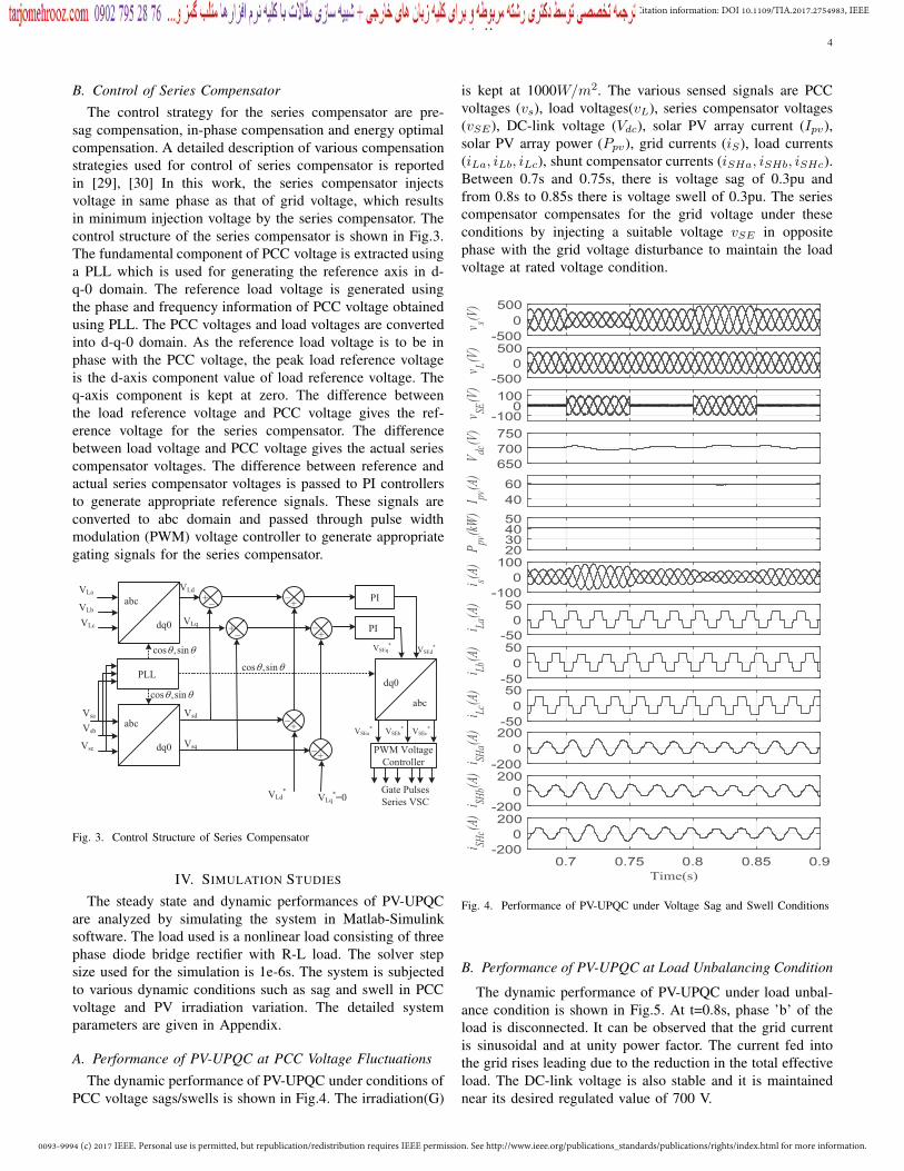
A. Performance of PV-UPQC at PCC Voltage FluctuationsThe dynamic performance of PV-UPQC under conditions of
PCC voltage sags/swells is shown in Fig.4. The irradiation(G)
is kept at 1000W/m2. The various sensed signals are PCCvoltages (vs), load voltages(vL), series compensator voltages(vSE), DC-link voltage (Vdc), solar PV array current (Ipv),solar PV array power (Ppv), grid currents (iS), load currents(iLa, iLb, iLc), shunt compensator currents (iSHa, iSHb, iSHc).Between 0.7s and 0.75s, there is voltage sag of 0.3pu andfrom 0.8s to 0.85s there is voltage swell of 0.3pu. The seriescompensator compensates for the grid voltage under theseconditions by injecting a suitable voltage vSE in oppositephase with the grid voltage disturbance to maintain the loadvoltage at rated voltage condition.
-5000
500
v s(V)
-5000
500
v L(V)
-1000
100
v SE(V
)650700750
Vdc
(V)
4060
I pv(A
)
20304050
Ppv
(kW)
-1000
100
i s(A)
-50050
i La(A
)
-50050
i Lb(A
)
-50050
i Lc(A
)
-2000
200
i SHa(A
)
-2000
200
i SHb(A
)
0.7 0.75 0.8 0.85 0.9Time(s)
-2000
200
i SHc(A
)
Fig. 4. Performance of PV-UPQC under Voltage Sag and Swell Conditions
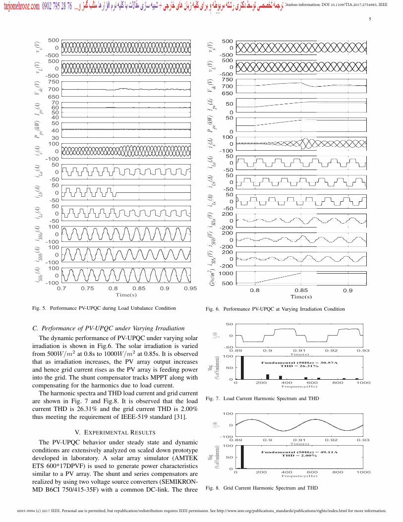
B. Performance of PV-UPQC at Load Unbalancing Condition
The dynamic performance of PV-UPQC under load unbal-ance condition is shown in Fig.5. At t=0.8s, phase ’b’ of theload is disconnected. It can be observed that the grid currentis sinusoidal and at unity power factor. The current fed intothe grid rises leading due to the reduction in the total effectiveload. The DC-link voltage is also stable and it is maintainednear its desired regulated value of 700 V.
0093-9994 (c) 2017 IEEE. Personal use is permitted, but republication/redistribution requires IEEE permission. See http://www.ieee.org/publications_standards/publications/rights/index.html for more information.
This article has been accepted for publication in a future issue of this journal, but has not been fully edited. Content may change prior to final publication. Citation information: DOI 10.1109/TIA.2017.2754983, IEEETransactions on Industry Applications
5
-5000
500 v s(V
)
-5000
500
v L(V)
650700750
Vdc
(V)
40506070
I pv(A
)
304050
Ppv
(kW)
-1000
100
i s(A)
-50050
i La(A
)
-50050
i Lb(A
)
-50050
i Lc(A
)
-1000
100
i SHa(A
)
-1000
100
i SHb(A
)
0.7 0.75 0.8 0.85 0.9 0.95Time(s)
-1000
100
i SHc(A
)
Fig. 5. Performance PV-UPQC during Load Unbalance Condition
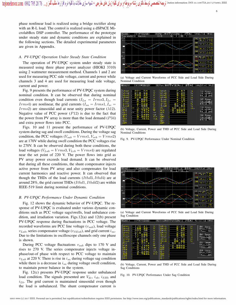
C. Performance of PV-UPQC under Varying Irradiation
The dynamic performance of PV-UPQC under varying solarirradiation is shown in Fig.6. The solar irradiation is variedfrom 500W/m2 at 0.8s to 1000W/m2 at 0.85s. It is observedthat as irradiation increases, the PV array output increasesand hence grid current rises as the PV array is feeding powerinto the grid. The shunt compensator tracks MPPT along withcompensating for the harmonics due to load current.
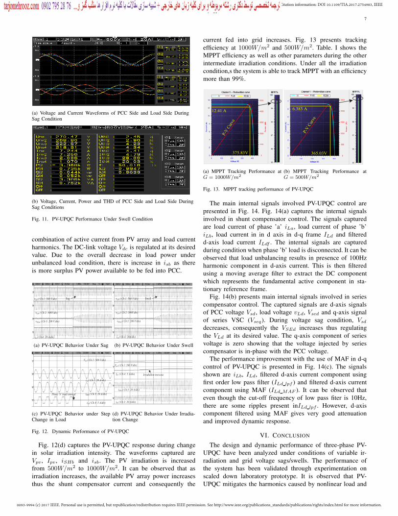
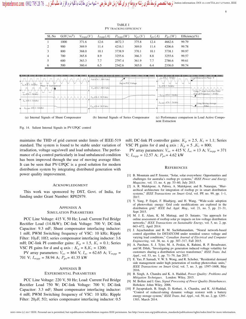
The harmonic spectra and THD load current and grid currentare shown in Fig. 7 and Fig.8. It is observed that the loadcurrent THD is 26.31% and the grid current THD is 2.00%thus meeting the requirement of IEEE-519 standard [31].
V. EXPERIMENTAL RESULTS
The PV-UPQC behavior under steady state and dynamicconditions are extensively analyzed on scaled down prototypedeveloped in laboratory. A solar array simulator (AMTEKETS 600*17DPVF) is used to generate power characteristicssimilar to a PV array. The shunt and series compensators arerealized by using two voltage source converters (SEMIKRON-MD B6CI 750/415-35F) with a common DC-link. The three
Fig. 6. Performance PV-UPQC at Varying Irradiation Condition
0.89 0.9 0.91 0.92 0.93Time(s)
-50
0
50
i L(A)
0 200 400 600 800 1000Frequency(Hz)
0
50
100
Fundamental (50Hz) = 30.57ATHD = 26.31%
Mag.
(% of
Fund
ament
al)
Fig. 7. Load Current Harmonic Spectrum and THD
0.89 0.9 0.91 0.92 0.93Time(s)
-100
0
100
i s(A)
0 200 400 600 800 1000Frequency(Hz)
0
50
100
Fundamental (50Hz) = 49.11ATHD = 2.00%
Mag.
(% of
Fund
ament
al)
Fig. 8. Grid Current Harmonic Spectrum and THD
0093-9994 (c) 2017 IEEE. Personal use is permitted, but republication/redistribution requires IEEE permission. See http://www.ieee.org/publications_standards/publications/rights/index.html for more information.
This article has been accepted for publication in a future issue of this journal, but has not been fully edited. Content may change prior to final publication. Citation information: DOI 10.1109/TIA.2017.2754983, IEEETransactions on Industry Applications
6
phase nonlinear load is realized using a bridge rectifier alongwith an R-L load. The control is realized using a dSPACE Mi-crolabBox DSP controller. The performance of the prototypeunder steady state and dynamic conditions are explained inthe following sections. The detailed experimental parametersare given in Appendix.
A. PV-UPQC Operation Under Steady State Condition
The operation of PV-UPQC system under steady state ismeasured using three phase power analyzer (HIOKI 3310)using 2 wattmeter measurement method. Channels 1 and 2 areused for measuring PCC side voltage, current and power whilechannels 3 and 4 are used for measuring load side voltage,current and power.
Fig. 9 presents the performance of PV-UPQC system duringnominal condition. It can be observed that during nominalcondition even though load currents (ILa = Irms3, ILc =Irms4) are nonlinear, the grid currents (Isa = Irms1, Isc =Irms2) are sinusoidal and at near unity power factor (λ12).Negative value of PCC power (P12) is due to the fact thatthe power from PV array is more than the load demand (P34)and extra power flows into PCC.
Figs. 10 and 11 present the performance of PV-UPQCsystem during sag and swell conditions. During the voltage sagcondition, the PCC voltages (Vsab = V rms1, Vscb = V rms2)are at 170V while during swell condition the PCC voltages riseto 270V. It can be observed during both these conditions, theload voltages (VLab = V rms3, VLcb = V rms4) are regulatednear the set point of 220 V. The power flows into grid asPV array power exceeds load demand. It can be observedthat during all these conditions, the shunt compensator injectsactive power from PV array and also compensates for loadcurrent harmonics and reactive power. It can observed thatthough the THDs of the load currents (Ithd3, Ithd4) are ataround 28%, the grid current THDs (Ithd1, Ithdd2) are withinIEEE-519 limit during nominal conditions.
B. PV-UPQC Performance Under Dynamic Condition
Fig. 12 shows the dynamic behavior of PV-UPQC. The re-sponse of PV-UPQC is evaluated under various dynamic con-ditions such as PCC voltage sags/swells, load unbalance con-dition, and irradiation variation. Figs.12(a) and 12(b) presentPV-UPQC response during fluctuations in PCC voltage. Therecorded waveforms are PCC line voltage (vsab), load voltagevLab, series compensator voltage (vSEab), and grid current isa.Due to the limitations in oscilloscope channels only one phaseis shown.
During PCC voltage fluctuations vsab dips to 170 V andrises to 270 V. The series compensator injects voltage in-phase/out-of phase with respect to PCC voltage to maintainvLab at 220 V. There is rise in isa during voltage sag conditionwhile there is a decrease in isa during voltage swell condition,to maintain power balance in the system.
Fig. 12(c) presents PV-UPQC response under unbalancedload condition. The signals presented are Vdc, isb, iSHb andiLb. The grid current is maintained sinusoidal even thoughthe load is unbalanced. The shunt compensator current is
(a) Voltage and Current Waveforms of PCC Side and Load Side DuringNominal Condition
(b) Voltage, Current, Power and THD of PCC Side and Load Side DuringNominal Conditions
Fig. 9. PV-UPQC Performance Under Nominal Condition
(a) Voltage and Current Waveforms of PCC Side and Load Side DuringSag Condition
(b) Voltage, Current, Power and THD of PCC Side and Load Side DuringSag Conditions
Fig. 10. PV-UPQC Performance Under Sag Condition
0093-9994 (c) 2017 IEEE. Personal use is permitted, but republication/redistribution requires IEEE permission. See http://www.ieee.org/publications_standards/publications/rights/index.html for more information.
This article has been accepted for publication in a future issue of this journal, but has not been fully edited. Content may change prior to final publication. Citation information: DOI 10.1109/TIA.2017.2754983, IEEETransactions on Industry Applications
7
(a) Voltage and Current Waveforms of PCC Side and Load Side DuringSag Condition
(b) Voltage, Current, Power and THD of PCC Side and Load Side DuringSag Conditions
Fig. 11. PV-UPQC Performance Under Swell Condition
combination of active current from PV array and load currentharmonics. The DC-link voltage Vdc is regulated at its desiredvalue. Due to the overall decrease in load power underunbalanced load condition, there is increase in isb as thereis more surplus PV power available to be fed into PCC.
vsab ( Ch 1: 500 V/div)
vLab ( Ch 2: 500V/div)
vSEab ( Ch 3: 200 V/div)
isa ( Ch 4: 20 A/div)
Sag
(a) PV-UPQC Behavior Under Sag
vsab ( Ch 1: 500 V/div)
vLab ( Ch 2: 500V/div)
vSEab ( Ch 3: 200 V/div)
isa ( Ch 4: 20A/div)
Swell
(b) PV-UPQC Behavior Under Swell
Vdc ( Ch 1: 500 V/div)
isb ( Ch 2: 20 A/div)
iSHb ( Ch 3: 20 A/div)
iLb ( Ch 4: 5 A/div)
Phase ‘b’ load removal
(c) PV-UPQC Behavior under StepChange in Load
Vpv ( Ch 1: 500 V/div)
isb ( Ch 2: 20 A/div)
iSHb ( Ch 3: 20 A/div)
Ipv ( Ch 4: 5 A/div) Irradiation increase
(d) PV-UPQC Behavior Under Irradia-tion Change
Fig. 12. Dynamic Performance of PV-UPQC
Fig. 12(d) captures the PV-UPQC response during changein solar irradiation intensity. The waveforms captured areVpv , Ipv , iSHb and isb. The PV irradiation is increasedfrom 500W/m2 to 1000W/m2. It can be observed that asirradiation increases, the available PV array power increasesthus the shunt compensator current and consequently the
current fed into grid increases. Fig. 13 presents trackingefficiency at 1000W/m2 and 500W/m2. Table. I shows theMPPT efficiency as well as other parameters during the otherintermediate irradiation conditions. Under all the irradiationcondition,s the system is able to track MPPT with an efficiencymore than 99%.
12.41 A
375.83V
P-V C
urve
(a) MPPT Tracking Performance atG = 1000W/m2
6.383 A
365.03V
P-V C
urve
(b) MPPT Tracking Performance atG = 500W/m2
Fig. 13. MPPT tracking performance of PV-UPQC
The main internal signals involved PV-UPQC control arepresented in Fig. 14. Fig. 14(a) captures the internal signalsinvolved in shunt compensator control. The signals capturedare load current of phase ’a’ iLa, load current of phase ’b’iLb, load current in in d axis in d-q frame ILd and filteredd-axis load current ILdf . The internal signals are capturedduring condition when phase ’b’ load is disconnected. It can beobserved that load unbalancing results in presence of 100Hzharmonic component in d-axis current. This is then filteredusing a moving average filter to extract the DC componentwhich represents the fundamental active component in sta-tionary reference frame.
Fig. 14(b) presents main internal signals involved in seriescompensator control. The captured signals are d-axis signalsof PCC voltage Vsd, load voltage vLd, Vsed and q-axis signalof series VSC (Vseq). During voltage sag condition, Vsd
decreases, consequently the VSEd increases thus regulatingthe VLd at its desired value. The q-axis component of seriesvoltage is zero showing that the voltage injected by seriescompensator is in-phase with the PCC voltage.
The performance improvement with the use of MAF in d-qcontrol of PV-UPQC is presented in Fig. 14(c). The signalsshown are iLb, ILd, filtered d-axis current component usingfirst order low pass filter (ILd lpf ) and filtered d-axis currentcomponent using MAF (ILd MAF ). It can be observed thateven though the cut-off frequency of low pass fiter is 10Hz,there are some ripples present inILd lpf . However, d-axiscomponent filtered using MAF gives very good attenuationand improved dynamic response.
VI. CONCLUSION
The design and dynamic performance of three-phase PV-UPQC have been analyzed under conditions of variable ir-radiation and grid voltage sags/swells. The performance ofthe system has been validated through experimentation onscaled down laboratory prototype. It is observed that PV-UPQC mitigates the harmonics caused by nonlinear load and
0093-9994 (c) 2017 IEEE. Personal use is permitted, but republication/redistribution requires IEEE permission. See http://www.ieee.org/publications_standards/publications/rights/index.html for more information.
This article has been accepted for publication in a future issue of this journal, but has not been fully edited. Content may change prior to final publication. Citation information: DOI 10.1109/TIA.2017.2754983, IEEETransactions on Industry Applications
8
TABLE IPV TRACKING EFFICIENCY
SL.No G(W/m2) Vmpp(V ) Impp(A) Pmpp(W ) Vpv(V ) Ipv(A) Ppv(W ) Efficiency(%)
1 1000 371.6 12.6 4672.3 375.8 12.4 4662.6 99.792 900 369.9 11.4 4216.1 369.0 11.4 4206.6 99.783 800 368.0 10.1 3738.9 370.1 10.1 3738.1 99.974 700 365.8 8.9 3255.6 366.3 8.8 3255.6 99.575 600 363.3 7.7 2797.4 361.9 7.7 2786.6 99.616 500 360.4 6.5 2342.6 365.0 6.4 2336.0 99.74
iLb (Ch 1: 5A/div)
iLa (Ch 1: 5A/div)
ILd (Ch 1: 5A/div)
ILd_MAF (Ch 1: 5A/div)
Phase ‘b’ load removal
(a) Internal Signals of Shunt Compensator
Vsd (Ch 1: 200 V/div)
VLd (Ch 2: 200 V/div)
VSE (Ch 3: 50 V/div)
VSEq (Ch 4: 50 V/div)
Sag in PCC Voltage
(b) Internal Signals of Series Compensator
iLb (Ch 1: 5A/div)
ILd (Ch 1: 5A/div)
ILd_Lpf (Ch 1: 5A/div)
ILd_MAF (Ch 1: 5A/div)
Load Removal in Phase ‘b’
Using 1st order Low Pass Filter (Cut-off Frequency = 10 Hz)
Using Moving Average Filter
(c) Performance comparison in Load Active Compo-nent Extraction
Fig. 14. Salient Internal Signals in PV-UPQC control
maintains the THD of grid current under limits of IEEE-519standard. The system is found to be stable under variation ofirradiation, voltage sags/swell and load unbalance. The perfor-mance of d-q control particularly in load unbalanced conditionhas been improved through the use of moving average filter.It can be seen that PV-UPQC is a good solution for moderndistribution system by integrating distributed generation withpower quality improvement.
ACKNOWLEDGMENT
This work was sponsored by DST, Govt. of India, forfunding under Grant Number: RP02979.
APPENDIX ASIMULATION PARAMETERS
PCC Line Voltage: 415 V, 50 Hz; Load: Current Fed BridgeRectifier Load (14.8kW); DC-link Voltage: 700 V; DC-linkCapacitor: 9.3 mF; Shunt compensator interfacing inductor:1 mH; PWM Switching frequency of VSC: 10 kHz; RippleFilter: 10μF, 10Ω; series compensator interfacing inductor: 3.6mH; DC-link PI controller gains: Kp = 1.5, Ki = 0.1; SeriesVSC PI gains for d and q axis : Kp = 8,Ki = 1200;
PV array parameters: Voc = 864 V, Isc = 62.65 A; Vmpp =701 V; Impp = 58.94 A; Ppv= 41.35 kW
APPENDIX BEXPERIMENTAL PARAMETERS
PCC Line Voltage: 220 V, 50 Hz; Load: Current Fed BridgeRectifier Load 750 W; DC-link Voltage: 700 V; DC-linkCapacitor: 3.3 mF; Shunt compensator interfacing inductor:4 mH; PWM Switching frequency of VSC: 10 kHz; RippleFilter: 20μF, 5Ω; series compensator interfacing inductor: 0.5
mH; DC-link PI controller gains: Kp = 2.5, Ki = 1.1; SeriesVSC PI gains for d and q axis : Kp = 5 ,Ki = 800;
PV array parameters: Voc = 415 V, Isc = 13 A; Vmpp = 371V; Impp = 12.57 A; Ppv= 4.62 kW
REFERENCES
[1] B. Mountain and P. Szuster, “Solar, solar everywhere: Opportunities andchallenges for australia’s rooftop pv systems,” IEEE Power and EnergyMagazine, vol. 13, no. 4, pp. 53–60, July 2015.
[2] A. R. Malekpour, A. Pahwa, A. Malekpour, and B. Natarajan, “Hier-archical architecture for integration of rooftop pv in smart distributionsystems,” IEEE Transactions on Smart Grid, vol. PP, no. 99, pp. 1–1,2017.
[3] Y. Yang, P. Enjeti, F. Blaabjerg, and H. Wang, “Wide-scale adoptionof photovoltaic energy: Grid code modifications are explored in thedistribution grid,” IEEE Ind. Appl. Mag., vol. 21, no. 5, pp. 21–31,Sept 2015.
[4] M. J. E. Alam, K. M. Muttaqi, and D. Sutanto, “An approach foronline assessment of rooftop solar pv impacts on low-voltage distributionnetworks,” IEEE Transactions on Sustainable Energy, vol. 5, no. 2, pp.663–672, April 2014.
[5] J. Jayachandran and R. M. Sachithanandam, “Neural network-basedcontrol algorithm for DSTATCOM under nonideal source voltage andvarying load conditions,” Canadian Journal of Electrical and ComputerEngineering, vol. 38, no. 4, pp. 307–317, Fall 2015.
[6] A. Parchure, S. J. Tyler, M. A. Peskin, K. Rahimi, R. P. Broadwater,and M. Dilek, “Investigating pv generation induced voltage volatility forcustomers sharing a distribution service transformer,” IEEE Trans. Ind.Appl., vol. 53, no. 1, pp. 71–79, Jan 2017.
[7] E. Yao, P. Samadi, V. W. S. Wong, and R. Schober, “Residential demandside management under high penetration of rooftop photovoltaic units,”IEEE Transactions on Smart Grid, vol. 7, no. 3, pp. 1597–1608, May2016.
[8] B. Singh, A. Chandra and K. A. Haddad, Power Quality: Problems andMitigation Techniques. London: Wiley, 2015.
[9] M. Bollen and I. Guo, Signal Processing of Power Quality Disturbances.Hoboken: Johm Wiley, 2006.
[10] P. Jayaprakash, B. Singh, D. Kothari, A. Chandra, and K. Al-Haddad,“Control of reduced-rating dynamic voltage restorer with a batteryenergy storage system,” IEEE Trans. Ind. Appl., vol. 50, no. 2, pp. 1295–1303, March 2014.
0093-9994 (c) 2017 IEEE. Personal use is permitted, but republication/redistribution requires IEEE permission. See http://www.ieee.org/publications_standards/publications/rights/index.html for more information.
This article has been accepted for publication in a future issue of this journal, but has not been fully edited. Content may change prior to final publication. Citation information: DOI 10.1109/TIA.2017.2754983, IEEETransactions on Industry Applications
9
[11] B. Singh, C. Jain, and S. Goel, “ILST control algorithm of single-stage dual purpose grid connected solar pv system,” IEEE Trans. PowerElectron., vol. 29, no. 10, pp. 5347–5357, Oct 2014.
[12] R. K. Agarwal, I. Hussain, and B. Singh, “Three-phase single-stage gridtied solar pv ecs using PLL-less fast CTF control technique,” IET PowerElectronics, vol. 10, no. 2, pp. 178–188, 2017.
[13] Y. Singh, I. Hussain, B. Singh, and S. Mishra, “Single-phase solar grid-interfaced system with active filtering using adaptive linear combinerfilter-based control scheme,” IET Generation, Transmission Distribution,vol. 11, no. 8, pp. 1976–1984, 2017.
[14] T.-F. Wu, H.-S. Nien, C.-L. Shen, and T.-M. Chen, “A single-phaseinverter system for pv power injection and active power filtering withnonlinear inductor consideration,” IEEE Trans. Ind. Appl., vol. 41, no. 4,pp. 1075–1083, July 2005.
[15] A. Javadi, A. Hamadi, L. Woodward, and K. Al-Haddad, “Experimentalinvestigation on a hybrid series active power compensator to improvepower quality of typical households,” IEEE Trans. Ind. Electron., vol. 63,no. 8, pp. 4849–4859, Aug 2016.
[16] A. Javadi, L. Woodward, and K. Al-Haddad, “Real-time implementationof a three-phase thseaf based on vsc and p+r controller to improve powerquality of weak distribution systems,” IEEE Transactions on PowerElectronics, vol. PP, no. 99, pp. 1–1, 2017.
[17] A. M. Rauf and V. Khadkikar, “Integrated photovoltaic and dynamicvoltage restorer system configuration,” IEEE Transactions on Sustain-able Energy, vol. 6, no. 2, pp. 400–410, April 2015.
[18] S. Devassy and B. Singh, “Design and performance analysis of three-phase solar pv integrated upqc,” in 2016 IEEE 6th International Con-ference on Power Systems (ICPS), March 2016, pp. 1–6.
[19] K. Palanisamy, D. Kothari, M. K. Mishra, S. Meikandashivam, andI. J. Raglend, “Effective utilization of unified power quality conditionerfor interconnecting PV modules with grid using power angle controlmethod,” International Journal of Electrical Power and Energy Systems,vol. 48, pp. 131 – 138, 2013.
[20] S. Devassy and B. Singh, “Modified p-q theory based control of solarpv integrated upqc-s,” IEEE Trans. Ind. Appl., vol. PP, no. 99, pp. 1–1,2017.
[21] S. K. Khadem, M. Basu, and M. F. Conlon, “Intelligent islanding andseamless reconnection technique for microgrid with upqc,” IEEE Journalof Emerging and Selected Topics in Power Electronics, vol. 3, no. 2, pp.483–492, June 2015.
[22] J. M. Guerrero, P. C. Loh, T. L. Lee, and M. Chandorkar, “Advancedcontrol architectures for intelligent microgrids;part ii: Power quality,energy storage, and ac/dc microgrids,” IEEE Transactions on IndustrialElectronics, vol. 60, no. 4, pp. 1263–1270, April 2013.
[23] B. Singh and J. Solanki, “A comparison of control algorithms fordstatcom,” IEEE Transactions on Industrial Electronics, vol. 56, no. 7,pp. 2738–2745, July 2009.
[24] B. Singh, C. Jain, S. Goel, A. Chandra, and K. Al-Haddad, “A multifunc-tional grid-tied solar energy conversion system with anf-based controlapproach,” IEEE Transactions on Industry Applications, vol. 52, no. 5,pp. 3663–3672, Sept 2016.
[25] S. Golestan, M. Ramezani, J. M. Guerrero, and M. Monfared, “dq-framecascaded delayed signal cancellation- based pll: Analysis, design, andcomparison with moving average filter-based pll,” IEEE Transactions onPower Electronics, vol. 30, no. 3, pp. 1618–1632, March 2015.
[26] R. Pea-Alzola, D. Campos-Gaona, P. F. Ksiazek, and M. Ordonez, “Dc-link control filtering options for torque ripple reduction in low-powerwind turbines,” IEEE Trans. Power Electron., vol. 32, no. 6, pp. 4812–4826, June 2017.
[27] S. Golestan, M. Ramezani, J. M. Guerrero, F. D. Freijedo, and M. Mon-fared, “Moving average filter based phase-locked loops: Performanceanalysis and design guidelines,” IEEE Trans. Power Electron., vol. 29,no. 6, pp. 2750–2763, June 2014.
[28] B. Subudhi and R. Pradhan, “A comparative study on maximum powerpoint tracking techniques for photovoltaic power systems,” IEEE Trans-actions on Sustainable Energy, vol. 4, no. 1, pp. 89–98, Jan 2013.
[29] A. Sadigh and K. Smedley, “Review of voltage compensation methodsin dynamic voltage restorer DVR,” in IEEE Power and Energy SocietyGeneral Meeting, July 2012, pp. 1–8.
[30] A. Rauf and V. Khadkikar, “An enhanced voltage sag compensationscheme for dynamic voltage restorer,” IEEE Trans. Ind. Electron.,vol. 62, no. 5, pp. 2683–2692, May 2015.
[31] “IEEE recommended practices and requirements for harmonic control inelectrical power systems,” IEEE Std 519-1992, pp. 1–112, April 1993.
Sachin Devassy (S’15, M’17) received B. Techin Electrical and Electronics Engineering in 2007from Govt. Engineering College, Thrissur, Kerala,India. He received M. Tech in Power Electronics,Electrical Machines and Drives from IIT Delhi in2010. He is currently working towards his PhDdegree in the Department of Electrical Engineering,IIT Delhi, New Delhi, India. He has been working inPower Electronics Group at CSIR-CEERI since July2010. His areas of research interest include powerelectronics, power quality, custom power devices and
renewable energy systems.
Bhim Singh (SM’99, F’10) was born in Rahamapur,Bijnor (UP), India, in 1956. He received his B.E.(Electrical) from the University of Roorkee, India, in1977 and his M.Tech. (Power Apparatus & Systems)and Ph.D. from the Indian Institute of TechnologyDelhi, India, in 1979 and 1983, respectively. In 1983,he joined the Department of Electrical Engineering,University of Roorkee (Now IIT Roorkee), as aLecturer. He became a Reader there in 1988. InDecember 1990, he joined the Department of Elec-trical Engineering, IIT Delhi, India, as an Assistant
Professor, where he has become an Associate Professor in 1994 and aProfessor in 1997. He has been ABB Chair Professor from September 2007 toSeptember 2012. Since October 2012, he is CEA Chair Professor. He has beenHead of the Department of Electrical Engineering at IIT Delhi from July 2014to August 2016. Since, August 2016, he is the Dean, Academics at IIT Delhi.He is JC Bose Fellow of DST, Government of India since December 2015.Prof. Singh has guided 65 Ph.D. dissertations, 167 M.E./M.Tech./M.S.(R)theses, and 60 BE/B.Tech. Projects. He has been filed 23 patents. He hasexecuted more than eighty sponsored and consultancy projects. He has co-authored a text book on power quality: Power Quality Problems and MitigationTechniques published by John Wiley & Sons Ltd. 2015. His areas of interestinclude solar PV grid interface systems, microgrids, power quality monitoringand mitigation, solar PV water pumping systems, improved power qualityAC-DC converters, power electronics, electrical machines, drives, FACTS,and high voltage direct current (HVDC) systems. Prof. Singh is a Fellow ofthe Indian National Academy of Engineering (FNAE), The Indian NationalScience Academy (FNA), The National Academy of Science, India (FNASc),The Indian Academy of Sciences, India (FASc), The World Academy ofSciences (FTWAS), Institute of Electrical and Electronics Engineers (FIEEE),the Institute of Engineering and Technology (FIET), Institution of Engineers(India) (FIE), and Institution of Electronics and Telecommunication Engineers(FIETE) and a Life Member of the Indian Society for Technical Education(ISTE), System Society of India (SSI), and National Institution of Quality andReliability (NIQR). He has received Khosla Research Prize of University ofRoorkee in the year 1991. He is recipient of JC Bose and Bimal K Bose awardsof The Institution of Electronics and Telecommunication Engineers (IETE) forhis contribution in the field of Power Electronics. He is also a recipient ofMaharashtra State National Award of Indian Society for Technical Education(ISTE) in recognition of his outstanding research work in the area of PowerQuality. He has received PES Delhi Chapter Outstanding Engineer Award forthe year 2006. Professor Singh has received Khosla National Research Awardof IIT Roorkee in the year 2013. He has also received Shri Om PrakashBhasin Award-2014 in the field of Engineering including Energy & Aerospace.He has been the General Chair of the 2006 IEEE International Conferenceon Power Electronics, Drives and Energy Systems (PEDES2006), GeneralCo-Chair of the 2010 IEEE International Conference on Power Electronics,Drives and Energy Systems (PEDES2010), General Co-Chair of the 2015IEEE International Conference (INDICON2015), General Co-Chair of 2016IEEE International Conference (ICPS2016) held in New Delhi.


![MON-AF-PO1.12-08 1 Combination of Flywheel Energy Storage ...tarjomehrooz.com/wp-content/uploads/2018/03/tarjomehrooz.com... · of application in power electronics [8]–[15]. By](https://img.pdfslide.us/doc/110x75/5e1b76b8de95a42a1158dfd8/mon-af-po112-08-1-combination-of-flywheel-energy-storage-of-application-in.jpg)


![1894 IEEE/ACM TRANSACTIONS ON AUDIO, …azadproject.ir/.../01/High-Precision-Parallel-Graphic-Equalizer.pdfof the equalizer filters, or band filters, ... [31]–[33]. This paper](https://img.pdfslide.us/doc/110x75/5af8066c7f8b9aac248c940e/1894-ieeeacm-transactions-on-audio-the-equalizer-lters-or-band-lters.jpg)